
Submitted:
24 December 2024
Posted:
24 December 2024
You are already at the latest version
Abstract
We compared the applicability of 3D fibrous scaffolds, produced by our patented centrifugal spinning technology, in soft tissue engineering. The scaffolds were prepared from four different biocompatible and biodegradable thermoplastics, namely polylactide (PLA), polycaprolactone (PCL), poly(3-hydroxybutyrate) (PHB), and poly(1,4-butylene succinate) (PBS) and their blends. The combined results of SEM and BET analyses revealed an internal hierarchically-organized porosity of the polymeric micro/nanofibers. Both nanoporosity and capillary effect are crucial for the water retention capacity of scaffolds designed for tissue engineering. The increased surface area provided by nanoporosity enhances water retention, while the capillary effect facilitates the movement of water and nutrients within the scaffolds. When the scaffolds were seeded with adipose-derived stem cells (ASCs), the ingrowth of these cells was the deepest in the PLA/PCL 13.5/4 (w/w) composite scaffolds. This result is consistent with the relatively large pore size in the fibrous networks, high internal porosity and large specific surface area found in these scaffolds, which may therefore be best suited as a component of adipose tissue substitutes that could reduce the postoperative tissue atrophy. Adipose tissue constructs produced in this way could be used in the future instead of conventional fat grafts, for example in breast reconstruction following cancer ablation.
Keywords:
micro/nanofibrous scaffolds
; centrifugal spinning technology
; tissue engineering
; PLA
; PHB
; PCL
; PBS
; bioartificial adipose tissue
; hierarchical inner porosity of fibers
; mesenchymal stem cells
1. Introduction
Tissue engineering combines isolated functional cells and a biodegradable biomaterial to promote the regeneration or repair of diseased or injured tissues. A highly porous scaffold plays a critical role in accommodating cells and guiding their growth and tissue regeneration in three dimensions. Nanofibrous scaffolds are considered to be one of the most suitable scaffolds for tissue engineering because they mimic the nanofibrous architecture of the natural extracellular matrix (ECM) (for a review, see [1]). Currently, a variety of techniques are available to create nanofibers, such as electrospinning (DC, AC), centrifugal spinning, centrifugal electrospinning, solution blow spinning, self-assembly, melt spinning, phase separation, or solid-free form fabrication [2].
The availability of a wide range of natural and synthetic biomaterials has widened the scope for the development of nanofibrous scaffolds. The three-dimensional (3D) synthetic biodegradable scaffolds designed using nanofibers serve as an excellent substrate for cell adhesion, proliferation, and differentiation. Therefore, nanofibers, irrespective of their method of fabrications, have been used as scaffolds for musculoskeletal tissue engineering (including bone, cartilage, ligament, and skeletal muscle), skin tissue engineering, vascular tissue engineering, neural tissue engineering, and as carriers for the controlled delivery of drugs, proteins, and DNA [3,4]. Tissue engineering uses a combination of cell biology, chemistry, and biomaterials to create 3D tissues that mimic the architecture of the native ECM, consisting of diverse interwoven nanofibrous structures. The unique properties of polymeric nanofibers make them a valuable tool to tissue engineers. In this field, the term “nanofiber” is typically used to describe fibers with diameters ranging from 1 to 1000 nm.
The small diameter of nanofibers closely matches the size scale of ECM fibers, allowing them to be used as biomimetic scaffolds, and the high surface area-to-volume ratio is ideal for cell attachment and drug loading. Compared to macroscale surfaces, nanofibers have shown higher rates of protein adsorption, a key mediator in cell attachment to a biomaterial surface. In addition, polymeric nanofibers have been shown to exhibit unique mechanical properties. In particular, tensile modulus, tensile strength and shear modulus have been shown to increase with decreasing fiber diameter [5]. Sustainable nanofibers in tissue engineering and biomedical applications, methods for their preparation [2] and nanofiber applications for wound dressing and tissue engineering [6] have recently been reviewed. Polymeric nanofibers can also be embedded in 3D-printed hydrogels to enhance cell-material interactions in biomedical applications. As a biomimetic scaffold, the nanofiber-reinforced hydrogels showed improved compressive modulus and cell growth [7].
The most widely used method for producing nanofibrous scaffolds is electrospinning. Most other nanofiber fabrication methods, such as melt-blowing, bicomponent fiber spinning, phase separation, template synthesis, and self-assembly, are complex and can only be used to produce nanofibers from a limited range of polymers. The production of nanofibrous scaffolds by the electrospinning process can be achieved using a variety of natural and synthetic biomaterials. The electrospinning process technology and its utility in tissue engineering of various tissues has been systematically reviewed [2,8]. Recent progress and possible future perspectives of electrospun nanofibrous scaffolds for bone tissue engineering, including drug/growth factor delivery for bone tissue regeneration, have been focused in another recent review paper [9]. Nemati et al. [10] highlighted the latest achievements in the fabrication of electrospun nanofibers, described various ways of modifying the surface and structure of scaffolds to promote their functionality, and also summarized the application of advanced polymeric nanofibrous scaffolds in the regeneration of human bone, cartilage, vascular tissues, and tendons/ligaments. Recently, Zulkifli et al. [11] provided an overview of the electrospinning techniques used to prepare nanofibers for tissue engineering applications. The authors described current research on nanofibers fabrication and characterization, including the main limitations of electrospinning and some possible solutions to overcome these limitations. Udomluck et al. [12] described the details of recently developed fabrication and post-modification techniques and discussed the advanced applications and impact of the integrated system of nanofiber-based scaffolds in the field of bone tissue engineering.
Among the various types of scaffolds, highly porous nanofibrous scaffolds are a potential candidate for supporting cell functions, such as adhesion and proliferation, delivering growth factors, and forming new tissue. Recent reports suggest that the chemical and physical properties of nanofibers can be tuned by post-spinning modification to regenerate specific target tissues. The possibilities of functionalizing of electrospun nanofibers for bone tissue engineering to make them more conducive and effective for bone regeneration have also been recently reviewed by Yan et al. [13].
Although the electrospinning method has been developed to produce nanofibrous scaffolds, their isotropic structure, low porosity, and small pore size prevent them from being widely used, especially for anisotropic tissues [14]. Electrospinning generally produces a nonwoven fibrous network with a typical pore size in the range from tens of nanometers to several micrometers, which is too small for the effective ingrowth of cells from most tissues into the scaffold. Therefore, the electrospinning technique has difficulty in directly producing clinically relevant 3D nanofibrous scaffolds with desired structural properties for most tissue engineering applications [14]. In addition, the technology also suffers from other drawbacks, such as the need for specialized equipment, high complexity, high electrical potential, electrically conductive targets, and very high purchase price. The widespread commercial use of electrospinning is mainly limited by its low production rate. The inability to produce large quantities of nanofibers has been a major obstacle to the further development and commercialization of electrospinning technologies. Erickson et al. [15] presented a high-throughput centrifugal electrospinning (HTP-CES) system capable of producing large numbers of highly-aligned nanofiber samples with high-yield and tunable diameters. Compared to conventional electrospinning techniques, fibers spun with the HTP-CES showed not only superior alignment, but also better diameter uniformity. This system can be easily scaled up for industrial production of highly-aligned nanofibers with tunable diameters, potentially meeting the requirements of various engineering and biomedical applications.
Centrifugal spinning is an alternative method for producing nanofibers from various materials at high speed and low cost. In 2008, Weitz et al. [16] reported unexpected findings of nanoscale fibers down to 25 nm in diameter emerging from a polymer solution during a standard spin-coating process. The fiber formation relies on the Raleigh-Taylor instability of the spin-coated liquid film, which arises from a competition between the centrifugal force and the Laplace force induced by the surface curvature. This process offers an attractive alternative to electrospinning for the efficient, simple, and nozzle-free production of nanoscale fibers from a variety of polymer solutions. In centrifugal spinning, the spinning fluid is introduced into a rotating spinning head. When the rotational speed reaches a critical value, the centrifugal force overcomes the surface tension of the spinning fluid to eject a jet of fluid from the nozzle tip or spinning edge of the spinning head. The jet then undergoes a stretching process and is finally deposited on the collector, forming solidified nanofibers. Centrifugal spinning is simple and enables rapid production of nanofibers for a wide range of applications. The centrifugal spinning process has been reviewed and compared with conventional nanofiber production methods [17].
Zhang et al. [18] introduced the working principle and development of high-speed centrifugal spinning. Unlike electrospinning, it does not require the electric field, and it could produce nanofibers in bulk from melt or solution materials. The jet motion and nanofiber formation process under the action of centrifugal force are explained in detail. The effects of equipment parameters and spinning solution parameters on the final nanofiber morphology are presented. These parameters are controllable and include spinneret rotational speed, nozzle length and diameter, spinning solution concentration, spinning solution viscosity and surface tension, and collection distance. A brief history of the centrifugal spinning method has also been recently reviewed [19]. The centrifugal spinning method stands out for its simplicity, high rate of fiber production, flexibility and easiness of its implementation when compared to the other methods. The high potential of the technique for use in the biomedical field has been emphasized. Marjuban et al. [20] overviewed the current advances in centrifugally spun polymeric fiber-based materials and their morphological features, performance, and characteristics for tissue engineering applications. The paper presents the fundamental process of fiber generation, and the effects of fabrication parameters (machine, solution) on the morphologies such as fiber diameter, distribution, alignment, porous features, and mechanical properties.
A comparative study of conventional electrospinning, centrifugal spinning and the basics of electro-centrifugal spinning has recently been published [21]. The surface tension and viscosity of the solutions are the spinnability determinants in these three methods, which are affected by the type of polymers and solvents and also by the concentration of the solution, and have to be overcome through electrical or centrifugal forces or both. The effective parameters of the process and the fiber morphology are investigated for each of the three methods in the aforementioned paper.
Simultaneous centrifugal spinning and solution blowing to form polymer nanofibers has also been reported [22]. The process is capable of producing 6 kg of fibers per hour and therefore offers mass production capabilities compared to other established polymer nanofiber generation methods such as electrospinning, centrifugal spinning, and blowing.
In industrial practice, electrospinning is mainly used to produce nanofibers, but centrifugal spinning and combined centrifugal spinning / electrospinning technologies are also used, albeit marginally and with different specificities for each method. We consider melt blowing, which can be tuned to produce submicron fibers, to be another technology with great potential for the production of nanofiber mats for tissue engineering, as it does not require the use of organic solvents and is quite environmentally friendly. However, melt-blowing technologies are limited to the use of thermoplastic polymers, such as polylactic acid (PLA), polycaprolactone (PCL), polyglycolic acid (PGA), polylactic glycolic acid (PLGA), polyhydroxyalkanoates (PHA), or polybutylene succinate (PBS).
As mentioned above, commercial electrospinning typically produces nanofibrous meshes that are relatively thin and have a two-dimensional (2D) morphology rather than the three-dimensional (3D) structure required for the reconstruction of most tissues. Control of the pore structure is an important aspect of scaffold fabrication, as it directly affects cell infiltration. Small average pore sizes result in reduced cellular infiltration. In some cases, infiltration can be limited to a very thin layer of cells on top of the nanofibrous scaffold. This phenomenon limits the potential benefits of the nanofibers for certain tissue engineering applications. The importance of the pore structure can be seen when comparing microfibrous and nanofibrous constructs. In some cases, the larger pore size of microfibrous scaffolds has been shown to promote higher levels of stem cell differentiation, in addition to improved cell infiltration [23].
The aim of our study was to verify the possibility of using our own patented nozzleless centrifugal spinning technology [24] to fabricate micro/nanofibrous hybrid scaffolds from several biocompatible and biodegradable polymers. We have created a bioartificial adipose tissue substitute using 3D micro/ nanofibrous scaffolds in combination with human adipose-derived stem cells (ASCs), which colonized these scaffolds and were able to differentiate into adipocytes (see Supplementary Materials). These adipose tissue analogues could be used in the future instead of classical fat grafts, applied e.g. for breast reconstruction after a cancer ablation procedure. We anticipate that our cell-material constructs could reduce postoperative atrophy.
2. Materials and Methods
2.1. Preparation of Fibrous Scaffolds
The NANOCENT centrifugal spinning demonstrator (DBH Technologies, Czech Republic) was used to fabricate the nanofibrous scaffolds (see Figure 1A). The demonstrator is based on a new method for producing micro/nanofibrous hybrid fibers and can be adapted to produce different types of fiber membranes and 3D constructs for use in a wide range of potential applications. The production of micro/nanofibrous hybrid scaffolds is based on a patented centrifugal technology [24], using a fiber-forming conical hollow disc, composed of a lower and an upper part forming an inner space with an outlet gap in between, connected to a hollow shaft and rotating around the axis at 1000 - 5000 rpm. A polymer solution is sprayed through orifices from the interior of the hollow shaft into the interior of the rotating disc. The fibers are formed by centrifugal force at the edge of the outlet gap and can be collected in the form of homogeneous mats on a cylindrical collector positioned next to the fiber-forming disc or using other types of collectors. The cotton wool-like fiber constructs used as scaffolds in our study were collected on the inner walls of the polyacrylate working tube of the Nanocent demonstrator (see Figure 1B,C). A two-piece plastic disc was used for all the experiments (see Figure 1B).
Poly(3-hydroxybutyrate) (PHB) (Biomer, Krailling, Germany), polylactide (PLA) Ingeo™ 4043D (NatureWorks, Plymouth, USA), poly(1,4-butylene succinate) (PBS), extended with 1,6-diisocyanatohexane (Sigma Aldrich, Prague, Czech Republic) and polycaprolactone (PCL), average Mn 80,000 (Sigma Aldrich, Prague, Czech Republic) were used in the experiments. All the polymers and their mixtures in chloroform (CF) were dissolved at 70°C under continuous shaking for 48 hours. The concentrations of individual polymers and their mixtures in CF and the parameters of the fiber formation process are summarized in Table 1.
2.2. Characterization of the Scaffold Microstructure by Scanning Electron Microscopy
Scanning Electron Microscopy (SEM) was used to analyze the particle size and morphology:
1) Fiber samples were fixed to the holders with double-sided adhesive tape and were examined in a Phenom G2 scanning electron microscope (Phenom-World BV, Eindhoven, Netherlands).
2) SEM scans were acquired by a scanning electron microscope (FIB-SEM, LYRA3 GMU, Tescan, Brno, Czech Republic). The applied acceleration voltage was 10 kV. The investigated samples were covered with a Pt conductive layer.
2.3. Brunauer-Emmett-Teller (BET) Analysis
Specific surface area and pore volume were determined from the adsorption and desorption isotherms on a NOVA3200 (Quantachrome Instruments, USA) using Quantachrome NovaWin software. Samples were degassed for 24 h at 100⁰C, and then nitrogen adsorption and desorption isotherms were recorded (Linde, 99.999%). Five-point BET analysis was used to determine specific surface area, and the 40-point Barrett–Joyner–Halenda (BJH) was used to determine pore volume. Each sample was measured four times with an experimental error of 5%.
2.4. Sterilization of the Prepared Fibrous Scaffolds
Before the experiments, the prepared scaffolds were sterilized by gamma-irradiation, using the basic sterilization dose (Microtron MT25, Nuclear Physics Institute, Academy of Sciences of the Czech Republic, Řež near Prague).
2.5. Cellular Component, Isolation and Characterization
The biocompatibility and permeability for the cell colonization of the prepared samples were tested with adult human mesenchymal stem cells. Adipose-derived stem cells (ASCs) were chosen because they can be differentiated into many cell types of mesenchymal origin, including chondrocytes, osteoblasts, smooth muscle cells and especially adipocytes, of which ASCs are de facto precursors (see Supplementary Materials). ASCs were isolated from lipoaspirates of subcutaneous abdominal adipose tissue of a healthy female donor (age 40 years) in accordance with the tenets of the Declaration of Helsinki on experiments involving human tissues, under the approval of the Ethics Committee of the „Na Bulovce“ Hospital, Prague, Czech Republic, and with written informed consent obtained from the donor prior to liposuction.
The isolation procedure was based on the original procedure published by Estes et al. [25] and further modified in our previous studies [26,27]. The ASCs were then used in passages 2-3, previously characterized by flow cytometry (Accuri C6 flow cytometer) to confirm the presence of typical mesenchymal stem cell markers (CD105, CD90, CD73, CD29) and the absence of markers of other cell types, such as hematopoietic cells and endothelial cells (CD45, CD34, CD31). The percentage of stem cell-specific CD markers was mostly higher than 98%. A more detailed description of the isolation, cultivation and characterization of ASCs can be found in our previous studies [26,27].
2.6. Cell Cultivation
The sterile scaffolds were cut into 10 x 10 x 3 mm samples, soaked in the culture medium (see below), placed in 24-well polystyrene plates (Techno Plastic Products, Trasadingen, Switzerland, inner well diameter 1.5 cm), and seeded with ASCs at a density of 300 000 cells/sample. The cells on the samples were cultured for 10 days in a Dulbecco's modified Eagle's Medium (DMEM; Sigma-Aldrich, St. Louis, MO, USA), supplemented with 10% fetal bovine serum (FBS; Sebak GmbH, Aidenbach, Germany), and gentamicin (40 μg/mL, LEK, Ljubljana, Slovenia) at 37°C in a humidified air atmosphere containing 5% CO2. Three to four independent samples were tested for each scaffold type. Cell behavior on the samples was evaluated on days 2, 6, and 10 after seeding.
2.7. Cell Visualization and Confocal Microscopy
Cell morphology, cell spreading on the scaffold fibers, scaffold overgrowth by cells, and cell ingrowth within the scaffolds were evaluated in cells visualized by fluorescence staining of the filamentous actin (F-actin). Prior to staining, the samples were fixed with 4% paraformaldehyde in phosphate-buffered saline for 30 minutes at room temperature. The samples were permeabilized with 0.1% Triton X-100 and 1% bovine serum albumin in phosphate-buffered saline for 20 minutes, followed by incubation in 1% Tween-20 in phosphate-buffered saline for 20 minutes. F-actin was then stained with Alexa Fluor 568-conjugated phalloidin (Thermo Fisher Scientific, Cat. No. A12380, 1000× diluted) for 1 hour at room temperature. Cell nuclei were counterstained with 4',6-diamidin-2-fenylindol (DAPI; Sigma-Aldrich, 32670, 20 μg/mL), added to the phalloidin solution. Microimages were captured using an Andor Dragonfly 503 scanning disc confocal microscope equipped with a Zyla 4.2 PLUS sCMOS camera (Andor Technology Ltd.) and an HC PL APO 20x/ 0.75 IMM CORR CS2 objective, allowing 3D visualization of the constructs and measurement of the depth of cell penetration into the scaffolds.
3. Results
3.1. Preparation of Fibrous Scaffolds
Conventional electrospinning typically produces 2D nanofibrous sheets rather than 3D nanofibrous constructs with pores large enough for cell colonization and desired tissue formation. Therefore, we have explored an alternative approach, namely the method of centrifugal spinning. This approach has been applied to various synthetic and nature-originated polymers [15,28,29,30], and even to the creation of ceramic nanofibers [31]. This technique does not use a high voltage field, and is therefore safer than electrospinning. It is also faster and has a higher throughput [22]. Our preliminary results have shown that centrifugal spinning is capable of producing nanofibrous cotton wool-like 3D scaffolds. Despite these encouraging results, centrifugally-spun scaffolds have several drawbacks that hinder cell penetration into the scaffolds and also scaffold vascularization. The main drawbacks are the low mechanical strength of micro/nanofibrous 3D constructs and the pore size in macro/nanofibrous networks, which is too small for successful cell colonization. For example, the formation of Haversian systems, i.e. concentric layers of osteoblasts with capillaries in the center, requires pores with a minimum diameter of 100 μm [32]. Another obstacle that complicates the fabrication of 3D fibrous constructs is the natural tendency of submicron fibers to form planar structures by self-assembly.
In our study, the 3D fiber „cotton wool-like constructs“ were prepared from the single polymers (PLA, PHB, PBS, and PCL) or several blends of the polymers (PHB/PLA 1/4; PHB/PBS 1/4, 2/7; PLA/PCL 5/1, 13,5/4 (w/w)). The centrifugal spinning parameters of the individual polymers and the polymer blends using the Nanocent Demonstrator are summarized in Table 1. Figure 1 shows the NANOCENT Demonstrator (DBH Technologies, Czech Republic) for the nozzleless centrifugal spinning technology used to produce the micro/nanofibrous hybrid fiber scaffolds (Figure 1A), equipped with the two-piece plastic disc (Figure 1B). The 3D polymeric fiber „cotton wool-like construct“ prepared by the technology described above is shown in Figure 1C.
3.2. Characterization of the Scaffold Microstructure by Scanning Electron Microscopy
3.2.1. Microstructure of the 3D Fiber „Cotton Wool-like Constructs“ Prepared from the Individual Polymers
PLA, PHB, and PBS formed a relatively dense network of micro/nanofibers, unsuitable for cell colonization due to their small pore size, typically in the order of units of micrometers, and only exceptionally up to tens of micrometers (see Figure 2). The prepared samples contained a mixture of fibers with diameters in the micrometer and submicrometer range. The PCL itself created a relatively dense network of coarser fibers that also contained a large number of non-fibrous planar structures.
3.2.2. Microstructure of the 3D Fiber „Cotton Wool-like Constructs“ Prepared from the Polymer Blends
PLA/PHB, PCL/PHB and PHB/PBS blends form relatively dense networks of micro/nanofibers with pore sizes again in the order of units to tens of micrometers, regardless of the ratio of each polymer in the blends (see Figure 3 and Figure 4). Larger pores were obtained with the PLA/PCL blend (see Figure 5, Figure 6 and Figure 7), regardless of the tested ratios of both polymers (5/1; 13.5/4 w/w). We have also tested the influence of the rotation speed of the spinning disc on the pore size of the PLA/PCL 3.5/4 w/w fibrous networks (see Figure 6A-F). The best results were obtained at a medium rotation speed of 3000 rpm (see Figure 6C, D). Further increases in disc speed have already resulted in a denser fiber structure and a reduction in pore size (see Figure 6E, F). The samples of the 3D fiber „cotton wool-like constructs“ prepared from PLA/PCL blends contained a greater amount of microfibers with diameters of several micrometers in combination with submicron fibers with relatively large pore sizes of up to tens of micrometers. Figure 7 shows a detail of the 13.5/4 (w/w) PLA/PCL microfiber, where the internal microporosity of the individual fibers is clearly visible. The pore size visible in Figure 7 is in the order of hundreds of nanometers. The potential influence of the internal microporosity of the individual fibers on the water retention of the fibrous scaffolds and cell attachment to the scaffold fibers is disscused below.
3.2.3. Use of PLA and PCL Composite Fibers and Optimal PLA/PCL Ratio in Fibrous Scaffolds for Tissue Engineering Applications
The use of 3D constructs prepared from PLA and PCL composite nanofibers and/or microfibers as biodegradable cell scaffolds for tissue engineering has already been described in a number of publications. PLA and PCL have been shown to be ideal for nanofiber fabrication in various biomedical applications due to their favorable properties, such as biodegradability and ability to promote cell growth, similar to native tissues. The optimal ratio of PLA and PCL in tissue engineering scaffolds is the subject of considerable research, as it significantly influences the mechanical properties, degradation rates, and biocompatibility of the resulting materials. Several studies have investigated different PLA/PCL ratios to determine the most effective combinations for specific tissue engineering applications. Research indicates that a 1:1 weight ratio of PLA to PCL is often optimal for achieving a balance between mechanical strength and flexibility. For instance, Liao et al. [33] found that electrospun PLA/PCL blend fibers prepared at a 1/1 ratio exhibited defect-free morphology, uniform diameter, and high ductility, making them suitable for tissue engineering applications. This ratio allows the beneficial properties of both polymers to be utilized, with PLA contributing to mechanical strength and PCL improving flexibility and degradation rates. In addition, Xu et al. [34] reported that the incorporation of PCL into PLA scaffolds improved the overall mechanical properties and biocompatibility, suggesting that a blend ratio of approximately PLA/PCL 7/3 may also be effective for certain applications. However, the specific findings regarding the optimal ratio for mechanical properties were not directly addressed in their study, which focused primarily on PCL scaffolds for bone tissue engineering.
Conversely, Kharaziha et al. [35] pointed out that varying the PLA/PCL ratio could manipulate the degradation rates of the scaffolds, which is critical for applications where controlled degradation is required to match tissue regeneration rates. They emphasized that a higher proportion of PCL could result in faster degradation, which may be desirable in certain tissue engineering contexts, such as in soft tissue applications. Moreover, Hairaldin et al. [36] found that a 9/1 ratio of PLA to PCL had superior mechanical properties compared to other ratios, highlighting the importance of optimizing the blend for specific mechanical requirements. This suggests that while a 1/1 ratio is often cited as optimal for general applications, specific tissue types may benefit from different ratios based on the mechanical and degradation properties required. Pisani et al. [37] prepared electrospun matrices suitable for circular replacement of esophageal defects from poly-L-lactide-co-poly-ε-caprolactone 7/3 ratio and characterized their physico-chemical and functional properties. PLA and PCL composite nanofibers have also been used to construct biodegradable artificial Anterior Cruciate Ligament (ACL) scaffolds, which must withstand mechanical stress during neoligament formation and stabilize the ACL [38]. The purpose of their study was to determine the effect of compositional variations in PLA and PCL on ultimate tensile strength and modulus of elasticity, fiber diameter, cytotoxicity level, degradation time and the tissue cell viability. The ideal scaffold was composed of PLA-PCL 8/2 (w/w), with an average fiber diameter of 827 ± 271 nm and a degradation time of approximately 219 days in phosphate-buffered saline solution. The higher the PCL, the lower the percentage of viable cells and the faster the degradation of the specimen.
To develop more clinically relevant 3D scaffolds, electrospun nanofibrous scaffolds with different weight ratios of PCL/PLA were fabricated via the thermally induced (nanofiber) self-agglomeration (TISA) method [39]. The results indicated that all of the 3D scaffolds were elastic/resilient and possessed interconnected and hierarchical pores with sizes ranging from sub-micrometers to ∼300 μm; therefore, the morphological structures of these scaffolds were similar to those of natural ECMs. The scaffolds with PLA/PCL 4/1 (w/w) ratio exhibited the best overall properties in terms of density, porosity, water absorption capacity, mechanical properties, bioactivity, and cell viability. Furthermore, alkaline phosphatase (ALP) activity, calcium content, and gene expression levels were also increased with increasing PLA weight ratio, likely due to the improved stiffness/bioactivity of the scaffold. By increasing the weight ratio of stiffer and more bioactive PLA in the 3D PCL/PLA blend scaffolds, the osteogenic differentiation of human mesenchymal stem cells (hMSCs) was enhanced. Future studies should continue to explore PLA/PCL ratios in conjunction with specific cell types and tissue engineering goals to further refine the optimal formulations. Both PCL and PLA nanofibrous scaffolds were safe and non-toxic to the cells evaluated, and both scaffolds supported cell attachment and proliferation of bone marrow and adipose tissue-derived mesenchymal stem cells [40].
The fabrication of a novel three-dimensional porous PCL/PLA tissue engineering scaffold with high connectivity for endothelial cell migration was also described. PLA electrospun membranes and PCL/PLA (70/30) films were first fused by hot pressing to obtain a composite film containing nanofibers. Supercritical fluid microfoaming technology was used to fabricate a nanofiber structure and a highly interconnected porous scaffold. Cross-sectional human umbilical endothelial cell (HUVEC) culture results showed that the scaffolds were biocompatible and significantly promoted the adhesion, migration, and penetration of HUVECs. Single-cell migration assays showed that the 3D porous scaffolds effectively promoted HUVEC migration [41]. Therefore, 3D porous PCL/PLA scaffolds have shown significant potential in the field of vascular patches. Dong et al. [14] used a modified electrospinning receiving system with a rotating mandrel and a water bath to fabricate a micro/nanofibrous PLA/PCL hybrid scaffold with anisotropic structure. The modified system promotes porosity and increased pore size. Compared with the nanofibrous scaffold prepared by the conventional electrospinning system, the hybrid scaffold consisted of oriented microfibers and random nanofibers. PLA/PCL electrospun membranes with tailored fiber diameters have also been used as drug delivery systems [42]. Poly(caprolactone-co-polylactic acid) nanofibrous scaffold in combination with 5-azacytidine and transforming growth factor-β to induce cardiomyocyte differentiation of adipose-derived mesenchymal stem cells was described by Tambrchi et al. [43].
While a 1/1 ratio of PLA to PCL is often reported as optimal for many tissue engineering applications due to its balanced properties, variations such as 7/3 or 9/1 may also be advantageous depending on the specific requirements of the tissue being engineered.
3.2.4. Influence of Fiber and Pore Size in Micro/Nanofibrous Mats on Cell Colonization
Although it is well known that centrifugal spinning can produce pores in nanofibrous structures that are up to an order of magnitude larger than those produced by the commonly used electrospinning method [44], the pore size is often still too small for effective colonization of the interior of nanofibrous structures. The optimal pore size in scaffold fiber networks has been extensively discussed in the scientific literature. A study by Shanmugasundaram et al. [23] evaluated the effect of scaffold design, specifically examining a range of nano- to micrometer-sized fibers, resulting pore size and mechanical properties, on the chondrogenic differentiation of human mesenchymal stem cells (MSCs) derived from the adult bone marrow. Chondrogenic markers, i.e. aggrecan, chondroadherin, Sox9 transcription factor and collagen type II, were highest for cells on micrometer-sized fibers (5 and 9 μm) with pore sizes of 27 and 29 μm, respectively, compared to cells on nano-sized fibers (300 nm and 600 to 1400 nm) with pore sizes of 2 and 3 μm, respectively. Micron-sized fibers with large pore structures and mechanical properties comparable to the cartilage ECM enhanced chondrogenesis.
Pore size in nanofibrous 3D scaffolds is a critical determinant of cell behavior, affecting cell migration, nutrient transport, and overall scaffold functionality in tissue engineering applications. The relationship between pore size and cell behavior is complex, and optimal pore size is essential for effective tissue regeneration. Research indicates that larger pore sizes generally facilitate cell infiltration and proliferation. For example, Guneta et al. [45] demonstrated that scaffolds with pore sizes greater than 100 μm significantly enhanced ASC proliferation, as these dimensions allow for adequate cell migration and nutrient flow. Similarly, Rad et al. [46] reported that their 3D scaffolds with average pore sizes greater than 20 μm, provided a suitable environment for cell penetration and proliferation compared to 2D scaffolds, emphasizing the importance of pore size in promoting cellular activities. In addition, Xu et al. [34] highlighted that their electrospun PCL scaffolds had interconnected pores with sizes up to approximately 300 μm, which not only supported cell proliferation but also mimicked the natural ECM. This interconnected pore structure is critical for maintaining a conducive environment for cell growth by allowing the diffusion of nutrients and the removal of metabolic waste, which is essential for maintaining cell viability.
Conversely, pores that are too large may reduce cell adhesion and proliferation. For example, Kim et al. [47] found that while microfibrous scaffolds can create a three-dimensional structure, their excessively large pore sizes can reduce the specific surface area available for cell attachment, thereby inhibiting cell proliferation. This suggests that there is an optimal range of pore sizes that must be maintained to balance the benefits of cell infiltration with the need for adequate surface area for cell adhesion. Furthermore, the specific pore size requirements may vary depending on the cell type involved. For instance, Hsia et al. [48] found that fibroblasts preferred pore sizes of 6-20 μm for optimal growth, while other cell types required larger pores. This variability underscores the importance of tailoring pore sizes to the specific cellular context of the tissue being engineered.
The typical pore size of electrospun nanofiber mats can vary significantly depending on several factors, including the polymer used, the electrospinning parameters, and the specific application for which the nanofiber mat is intended. In general, the pore sizes in electrospun nanofiber mats range from several hundred nanometers to several micrometers. For example, Samie et al. [49] reported that the average pore diameter in their electrospun nanofiber mats was approximately 863 ± 142 nm and 925 ± 124 nm for different samples, indicating a relatively small pore size suitable for applications such as tissue engineering. Similarly, Lembach et al. [50] found that the size of the interfiber pores in electrospun nanofiber mats is typically on the order of a few micrometers. However, Wulkersdorfer et al. [51] showed that by varying the humidity during the electrospinning process, they achieved pore sizes ranging from 900 to 5000 μm², demonstrating the tunability of pore dimensions based on environmental conditions. This flexibility is further supported by Jeong et al. [52], who noted that large pores, typically over a few micrometers, can be obtained using specific electrospinning techniques, although such large pores may limit the applicability of the material in certain contexts.
The use of various additives and techniques can further influence the pore size. A number of strategies have been developed to increase the pore size of electrospun 3D nanofibrous constructs while maintaining their nanoscale features [5]. These include salt leaching techniques, where salt crystals are mixed with the fibers during fabrication and leached out after spinning [53], formation of ice crystals on the collecting plate, which results in larger pores in the construct after melting the ice crystals [54], using a dual electrospinning setup where the additional polymer stream is used to create sacrificial fibers that are eluted after spinning, increasing the void space in the construct [55], using a spherical collecting dish with metallic pegs dispersed throughout to form an uncompressed, cotton ball-like mesh of nanofibers [56], or dispersing nanofibers within a microfiber framework [57]. Mahjour et al. [58] discussed methods such as sacrificial microbeads and cryogenic electrospinning to increase porosity and pore size in electrospun matrices, which can be crucial for applications requiring improved cell infiltration. This is echoed by Lee et al. [59], who emphasized that the high porosity and surface area of electrospun nanofibers are advantageous for tissue engineering applications. However, the options for increasing the pore size in electrospun matrices to meet the requirements for successful cell penetration into the materials are limited, and the methods described above are quite complicated, laborious, difficult to reproduce, reduce the mechanical strength of the nanofiber constructs and often require non-standard design modifications to existing devices.
In summary, the pore size of nanofibrous scaffolds significantly influences cell colonization by affecting cell adhesion, migration, proliferation and nutrient transport. While larger pores generally promote cell infiltration and growth, pores that are too large or too small can have detrimental effects. Therefore, careful design and optimization of pore sizes are essential for developing effective scaffolds for tissue engineering applications. Our results demonstrated that our nozzleless centrifugal spinning technique can easily produce the 3D fiber „cotton wool- like constructs“ with larger pores than the electrospinning equipment, typically up to the size of tens of micrometers (see Figure 3, Figure 4, Figure 5, Figure 6 and Figure 7).
3.3. BET Analysis
3.3.1. Results of BET Analysis of Micro/Nanofibrous Hybrid Fibrous Scaffolds Prepared from Single Polymers and from 5/1 and 13.5/4 (w/w) PLA/PCL Blends
Nanofibrous materials are characterized by their extremely high surface area, which is a critical property that enhances their functionality across various applications. The specific surface area of nanofibrous materials is influenced by several factors including fiber diameter, manufacturing method, and material composition. For example, reducing the fiber diameter from micrometers to nanometers results in a significant increase in specific surface area, which is critical for applications such as filtration, tissue engineering, and drug delivery systems. Table 2 shows the BET analysis results of our micro/nanofibrous hybrid biodegradable scaffolds. The specific surface areas of the PLA and PHB fibrous constructs are relatively low due to the high content of microfibers and relatively high pore sizes in the fibrous networks, in the range of approximately 12 to 16 m2.g-1. The BJH pore sizes, corresponding to the nanoporosity of the pore size of 2 - 50 nm, are in the range of 0.013 - 0.018 cm3.g-1. However, the addition of PLA to PCL resulted in a significant increase in both the specific surface area and BJH pore size, which was particularly evident in the PLA/PCL 13.5/4 scaffolds. Therefore, in addition to the microporosity of the individual fibers visible in the SEM images (pore size in the order of hundreds of nanometers, see Figure 7), the BET analysis revealed the internal nanoporosity of the fibers in the order of units of nanometers. The BET analysis of material porosity is limited to the range of pore sizes from about 2 nm to 20 nm, and is unable to detect smaller and larger pores. Therefore, only the combined results of SEM and BET analyses revealed the hierarchical porosity of the polymeric micro/nanofibers produced by the centrifugal spinning. The hierarchical porosity of the produced polymeric micro/nanofibrous scaffolds can significantly influence their water retention ability and fiber roughness, as discussed in more detail below.
3.3.2. Effect of Micro/Nanofiber Surface Roughness on Cell Colonization
The combined results of SEM and BET analyses revealed the internal hierarchical porosity of the produced polymeric micro/nanofibers produced by the centrifugal spinning (see Figure 7, Figure 8 and Figure 9 and Table 2), which can influence the surface roughness of the fibers, which is usually in the submicrometer or nanoscale range. PLA fibers with increased nanoscale surface roughness and porosity showed a trend towards higher cell attachment and proliferation [28]. The roughness of nanofibrous scaffolds significantly influences cell attachment, which is a critical factor in tissue engineering applications. Surface roughness can affect cellular behavior such as adhesion, proliferation, and differentiation, ultimately impacting the effectiveness of the scaffold in promoting tissue regeneration. Nanofibrous scaffolds with increased nanoscale surface roughness have been shown to improve cell adhesion. For instance, Zhang et al. [60] reported that the incorporation of β-tricalcium phosphate (β-TCP) nanoparticles into gelatin nanofibers resulted in a rough surface that promoted osteoblast adhesion and proliferation, as well as osteogenic differentiation. This nanoscale roughness provides more surface area for cells to anchor, facilitating the formation of focal adhesions, which are critical for cell signaling and communication with the ECM [61]. Similarly, Liu et al. [62] demonstrated that the regulated surface morphology of polyaniline/polylactic acid composite nanofibers improved biocompatibility and cell adhesion due to the increased surface area provided by the rough texture. Moreover, nanofiber roughness can influence the spatial organization of cells. Gittens et al. [63] highlighted that nanoscale surface features can significantly affect osteoblast behavior, including adhesion and differentiation, suggesting that specific roughness patterns can guide cellular responses. This is particularly relevant in applications where directional growth is desired, such as nerve regeneration, where aligned and rough nanofibers can guide cell migration and orientation [64].
In addition to promoting adhesion, rough surfaces can also enhance the retention of bioactive molecules, which can further stimulate cell attachment and proliferation. For example, Oktay et al. [65] found that collagen-modified nanofibrous scaffolds exhibited improved cell attachment and growth rates, which they attributed to the roughness facilitating better cellular interactions with collagen. The increased surface area allows for more effective binding of growth factors and ECM proteins, which are essential for cell survival and function. On surfaces with nanoscale roughness, the cell adhesion-mediating molecules are adsorbed in an advantageous, near-physiological and flexible conformation, which facilitates the binding of the active sites in these molecules, e.g. specific amino acid sequences such as RGD, by cell adhesion receptors, such as integrins (for a review, see [1]).
However, it is important to note that while increased roughness may enhance cell attachment, excessively rough surfaces may inhibit cell spreading and migration. For example, Dubey et al. [66] observed that vascular endothelial cells performed better on smoother surfaces compared to rough electrospun surfaces, suggesting that there is an optimal range of roughness that balances adhesion and cell mobility. Nanoscale surface roughness typically promotes cell attachment, spreading and subsequent proliferation, whereas microscale surface roughness may inhibit these processes. This is because mammalian cells typically spread over tens of micrometers, thus microscale irregularities can interfere with this process. Specifically, cells must adhere to depressions between protrusions that limit their spreading area, or they must bridge these protrusions, thereby not using the entire ventral surface of their cell membrane to interact with their adhesion substrate. If they adhere to both protrusions and depressions, they must bend unphysiologically, mechanically stressing their cell membrane. As a result, the cells proliferate more slowly, although they may achieve a higher degree of differentiation, such as osteogenic differentiation (for a review, see [1]). Therefore, careful design and optimization of nanofiber roughness are necessary to achieve the desired cellular responses.
In summary, the roughness of nanofibrous scaffolds plays a pivotal role in influencing cell attachment. By increasing surface area and promoting favorable interactions with cells, rough nanofibers can significantly improve adhesion, proliferation, and differentiation, making them valuable in tissue engineering applications. Future research should focus on optimizing surface roughness to balance cell attachment and mobility for specific tissue engineering needs.
3.3.3. Effect of Internal Porosity of Individual Micro/Nanofibers on Cell Colonization
The combined results of SEM and BET analyses revealed the internal hierarchical porosity of the polymeric micro/nanofibers produced by the centrifugal spinning (see Figure 7, Figure 8 and Figure 9 and Table 2). The internal structure of nanofibers is characterized by a combination of molecular orientation, component distribution, and the presence of additional materials, all of which contribute to their overall performance. The ability to manipulate these internal structures through various fabrication techniques opens up new avenues for enhancing the functionality of nanofibers in advanced applications. Based on the internal structure, nanofibers are classified into non-porous, mesoporous, hollow and core-shell fibers [67]. Nanofibers can exhibit hierarchical internal porosity, which is a significant advance in materials science, particularly for applications in catalysis, drug delivery, and filtration. Hierarchical porosity refers to the presence of pores at multiple scales within the nanofibers, which enhances their functionality by increasing surface area and providing pathways for mass transport [68]. For example, Chen et al. [69] described coaxial porous nanofibers formed through a non-solvent-induced phase separation, resulting in uniform small pores conducive to sustained drug release applications.
Controlling the porosity of nanofibers is crucial for their performance in various applications. For example, Abolhasani et al. [70] discussed methods to hierarchically engineer porosity within nanofibers, emphasizing the importance of controlling thermodynamic and kinetic parameters during fabrication to achieve desired pore structures. Moreover, the use of sacrificial materials and phase separation techniques has been shown to facilitate the creation of complex porous architectures, as evidenced by the work of Gulfam et al. [71], who reported the selective removal of core materials to create hollow or porous structures in polymeric fibers.
In terms of practical applications, the hierarchical porosity of nanofibers significantly enhances their performance. In addition, the high porosity of nanofibers can improve their ability to absorb exudates in wound dressings, as shown by Serag et al. [72], who found that increased porosity allowed for better nutrient exchange and fluid management at wound sites. Furthermore, the synthesis of porous nanofibers can be tailored to meet specific functional requirements. For example, You et al. reported cigar-shaped TiO2 nanofibers with hierarchical internal structures that enhanced their mechanical and electrochemical performance, demonstrating the versatility of hierarchical porosity in energy storage applications [73]. Similarly, the work of Nathani and Sharma [74] showed that the sensitivity of biosensors could be significantly improved by optimizing the porosity of electrospun nanofibers. The ability to create nanofibers with hierarchical internal porosity opens up numerous possibilities for advanced materials applications. The combination of different fabrication techniques allows for the precise control of pore structures, which can be tailored to improve the performance of nanofibers in areas such as catalysis, drug delivery and environmental remediation.
The internal porosity of polymeric nanofibers can play a critical role in tissue engineering applications by influencing several key factors, including cell attachment, nutrient transport, and mechanical properties of the scaffolds. The hierarchical porosity within these nanofibers enhances their performance as scaffolds for tissue regeneration, making them highly suitable for mimicking the ECM of native tissues. First, the presence of internal porosity significantly increases the surface area of the nanofibers, which is essential for promoting cell attachment and proliferation. As highlighted by Dahlin et al. [5], the large surface area provided by electrospun nanofibers facilitates better interaction with cells and bioactive factors, thereby enhancing cellular activities crucial for tissue engineering. Moreover, the porous structure allows for improved nutrient and waste transport, which is essential for maintaining cell viability and function within the scaffolds. Kalaoglu-Altan et al. [75] found that the three-dimensional, porous scaffold architecture of polymeric nanofibers provides excellent properties for cell growth and biomolecular immobilization, which are critical for effective tissue regeneration. In addition, the mechanical properties of nanofibers can be tailored by manipulating their porosity. Linh et al. [76] discussed how the degradation behavior of polyvinyl alcohol/gelatin nanofiber composites is influenced by their inner structure, which in turn affects their mechanical integrity and suitability as biodegradable scaffolds. The ability to control porosity allows for the optimization of stiffness and flexibility, ensuring that the scaffolds can withstand physiological loads while providing the necessary support for tissue growth.
Furthermore, the hierarchical porosity can be engineered to create specific microenvironments that promote desired cellular responses. For example, the work of Wang et al. [77] highlights the importance of creating biomimetic structures that not only mimic the physiological properties of the ECM, but also provide biochemical cues for cell differentiation and tissue formation. The incorporation of growth factors or other bioactive molecules into the porous structure can further enhance the functionality of the scaffolds, as demonstrated by Oliveira et al. [78], who investigated the binding of growth factors to nanofibrous substrates to promote fibroblast activity. Moreover, the degradation rate of the nanofibers, which is critical for tissue engineering applications, can also be influenced by their porosity. As noted by Priyanto et al. [79], the porosity of nanofibers affects their interaction with body fluids, thereby influencing their degradation behavior and the release of encapsulated therapeutic agents. This controlled degradation is essential for scaffolds to provide temporary support while allowing for the gradual replacement by natural tissue.
Therefore, the influence of nanoporosity on water retention in tissue engineering scaffolds is a critical factor affecting the performance and functionality of these materials. Nanoporosity increases the ability of scaffolds to retain water, which is essential for maintaining a suitable environment for cell growth and tissue regeneration. The relationship between nanoporosity and water retention can be understood through several mechanisms, including increased surface area, improved hydrophilicity, and enhanced nutrient diffusion. First, the presence of nanoporosity significantly increases the specific surface area of scaffolds, which allows for greater water retention. Depan and Misra [80] emphasize that scaffolds with nanostructured features exhibit favorable water retention behavior, which is conducive to cell adhesion and proliferation. This is particularly important in tissue engineering, where the scaffolds must provide a supportive environment for cell growth. The retained moisture not only promotes cell adhesion but also enhances signal-transduction pathways that are crucial for cellular activities.
Moreover, the hydrophilicity of scaffolds is often enhanced by their nanostructured surfaces. For instance, Ghalei et al. [81] found that electrospun scaffolds with increased wettability allow for better cell attachment, which is directly related to improved water retention capabilities. This wettability is influenced by the size and distribution of nanopores, which can trap water molecules and create a favorable microenvironment for cells. Additionally, the study by Li et al. [82] highlights that hydrogels with high water content are essential for effective wound healing, further emphasizing the importance of water retention in tissue engineering applications. Capillary action plays an important role in the water retention capacity of tissue engineering scaffolds. The interconnected pores created by nanoporosity facilitate the movement of water through the scaffold, allowing for effective nutrient diffusion and waste removal. Zhao et al. [83] highlighted that the ability of scaffolds to absorb and retain fluids is critical for maintaining a hydrated wound bed, which is essential for skin regeneration. The capillary forces generated by the porous structure allow the scaffolds to draw water into their matrix, thereby improving hydration and nutrient availability to cells.
The internal porosity of polymeric nanofibers is a critical factor in their application for tissue engineering. It enhances cell attachment and proliferation, optimizes mechanical properties, and allows for the controlled release of bioactive substances, all of which contribute to effective tissue regeneration. The ability to engineer these porous structures opens up new avenues for the development of advanced scaffolds tailored to specific tissue engineering needs. Both nanoporosity and capillary effects are fundamental to the water retention capabilities of tissue engineering scaffolds. The increased surface area provided by nanoporosity enhances water retention, while capillary action facilitates the movement of water and nutrients within the scaffolds.
Taken together, these factors help to create a suitable environment for cell growth and tissue regeneration, making them essential considerations in the design of scaffold for tissue engineering applications. For these purposes, we tested the scaffolds prepared from single polymers (PLA, PHB, PBS, and PCL) and several copolymers, namely PHB/PLA 1/4; PHB/PBS 1/4, 2/7; PLA/PCL 5/1, 13,5/4 (w/w).
3.4. Biocompatibility and Cell Colonization of the Prepared Scaffolds
3.4.1. Comparison of Cell Colonization of Selected Scaffolds
We investigated the biocompatibility of nanofibrous scaffolds prepared from single polymers (PLA, PHB) and different blends of these polymers with PBS or PCL (PHB/PLA 1/4; PHB/PBS 1/4, 2/7; PLA/PCL 5/1, 13,5/4 (w/w)). We tested the colonization of five different scaffolds with ASCs during 10 days of cultivation time. We visualized the cells by fluorescence staining and monitored the adhesion, growth and survival of the cells on the tested samples, as well as the penetration of the cells into the scaffolds. The comparison of cell ingrowth thickness in different scaffold types is shown in Table 3.
The single polymer scaffolds were usually colonized by cells only on the surface, and even with prolonged cultivation, there was no penetration of cells to a greater depth (the maximum cell penetration depth was 88-174 µm, Table 3). From this point of view, the polymer blends are preferable. Cell visualization to illustrate the depth of cell penetration into three selected scaffolds, i.e. a single polymer scaffold (PLA) and two blends, i.e. PLA/PHB 4/1 w/w and PLA/PCL 13.5/4 w/w, was performed by fluorescent staining with phalloidin. Cell adhesion, spreading, proliferation and scaffold colonization differed between the different materials. The situation on day 10 is shown in Figure 10. The PLA scaffolds were very poorly colonized, with only a few cells visible in the top view of the scaffolds. The side view showed that cells had penetrated into the material, but at a very low density. The PLA/PHB scaffolds were the most densely populated, but the cells remained mostly on the surface of the scaffolds where they formed a dense crust with almost no cell penetration inside the scaffolds. In contrast, the PLA/PCL scaffolds were less colonized with cells on their surface, but a significant number of cells migrated into the interior of the scaffolds and colonized them in depth.
3.4.2. Time Course of PLA/PCL Scaffold Colonization
Since the PLA/PCL 13.5/4 (w/w) scaffolds proved to be the most suitable for colonization with ASCs, we tested their colonization with these cells over the course of 10 days. Samples were evaluated on day 2, day 6, and day 10 after seeding (Figure 11). We observed a marked progression in the depth of ASC colonization. After 10 days, the cells were visible in the cell-material construct to a depth of nearly 500 µm, which is the maximum depth that can be resolved with a given microscope.
3.4.3. Cell Morphology on PLA/PCL Scaffolds
Cells on PLA/PCL 13.5/4 (w/w) scaffolds were well-spread with either a polygonal or elongated morphology typical of well-adhered cells at partial confluence (Figure 12). Cells were often elongated along the fibers of the scaffolds.
3.4.4. Suitability of the Scaffolds from a Biological Point of View
The predicted suitability of the scaffold for use in tissue engineering depends on whether the scaffold is colonized by the appropriate cell type. This colonization depends on the pore size, which can be determined by SEM. The actual depth of cell penetration into the scaffold can be continuously monitored and determined by confocal microscopy, as we have done in our previous work [84]. Centrifugal spinning of single polymers, such as PLA, PHB or PCL, formed relatively dense networks of micro/nanofibers with pore sizes in the order of units to tens of micrometers, which were less suitable for cell colonization. PLA/PHB, PCL/PHB and PHB/PBS blends again formed similarly dense networks, regardless of the ratio of individual polymers in the blends (see Figure 3 and Figure 4). Larger pores were obtained with the PLA/PCL blends (see Figure 5, Figure 6 and Figure 7), regardless of the tested ratios of both polymers (5/1; 13,5/4 w/w). The scaffold permeability to cells, i.e. the comparison of the depth to which the cells migrated inside the scaffolds, confirmed the highest suitability of the PLA/PCL 13.5/4 (w/w) fibrous scaffold, which showed the deepest ingrowth of ASCs. This result is consistent with the assumption that 3D scaffolds with a high porosity, large pore size, large specific surface area and nanoporosity of the fibers are most suitable for use as a component of adipose tissue substitutes that could reduce postoperative tissue atrophy after reconstructive surgery. Adipose tissue constructs produced in this way could be used in the future instead of conventional fat grafts, for example in breast reconstruction after cancer ablation.
Therefore, we also tested the growth of ASCs on scaffolds in adipogenic medium containing DMEM supplemented with 10% of FBS, 1 μM dexamethasone, 20 μM indomethacin, 10 μg/mL insulin and and 500 μM 3-isobutyl-1-methylxanthine (IBMX). We obtained similar results as in the standard culture medium, i.e. the cells were able to grow on the surface of the scaffolds as well as to penetrate into their depths, although the scaffolds in the differentiation medium were less densely populated than in the standard growth medium without adipogenic supplements (see Figure 10 and Figure 13). For this reason, some pre-cultivation of the cells in a growth medium would be desirable.
4. Conclusions and Further Perspectives
The aim of our study was to verify the feasibility of using our own patented nozzle-free centrifugal technology to produce micro/nanofibrous hybrid scaffolds from various biocompatible and biodegradable polymers.
We found that single polymers, such as PLA, PHB, PBS and PCL formed a relatively dense network of micro/nanofibers that were unsuitable for cell colonization due to small pore sizes, typically on the order of units of micrometers, but exceptionally up to tens of micrometers. Similarly, PLA/PHB, PCL/PHB and PHB/PBS blends again formed relatively dense networks with pore sizes on the order of units to tens of micrometers, regardless of the ratio of individual polymers in the blends. The largest pores (in tens of micrometers) were obtained with the PLA/PCL blends, regardless of the tested ratios (5/1; 13.5/4 w/w) of both polymers.
The combined results of SEM and BET analyses revealed the hierarchical porosity of the polymeric micro/nanofibers produced by the centrifugal spinning. In addition to the microporosity of the individual fibers visible in the SEM images (pore size in the order of hundreds of nanometers), the BET analysis revealed internal nanoporosity of the fibers with pore size in the range of 1-14 nm. The addition of PLA to PCL resulted in a significant increase in both the specific surface area and BJH pore size (2-20 nm). The hierarchical porosity of our polymeric micro/nanofibrous scaffolds can significantly influence their water retention capacity and fiber roughness, which are important for cell colonization of the scaffolds and their applicability in tissue engineering.
Based on the relatively large pore size of the fiber networks, high internal porosity, and large specific surface area of the 3D fiber constructs, we evaluated the sample of PLA/PCL 13.5/4 (w/w) blend sample as the material with the most favorable properties for cell colonization. Measurement of the thickness of the layer into which cells migrated on different types of scaffolds confirmed that the PLA/PCL 13.5/4 (w/w) fibrous scaffolds showed the deepest ASC ingrowth.
We therefore created a bioartificial adipose tissue substitute using 3D micro/nanofibrous “cotton wool-like“ scaffolds in combination with ASCs, which are precursors of adipocytes, capable of differentiating into this cell type. These adipose tissue analogues could be used in the future instead of classical fat grafts, applied e.g. for breast reconstruction after a cancer ablation procedure. We expect that our cell-material constructs could reduce post-operative atrophy.
Supplementary Materials
The following supporting information can be downloaded at the website of this paper posted on Preprints.org.
Author Contributions
Conceptualization, M.B. and J.M; methodology, M.B., J.M., A.S., P.S. and Z.K.; software, J.M. and O.V.; validation, M.B., J.M., P.S., Z.K., L.B; formal analysis, J.M., A.S., M.V., O.V. and Z.K.; investigation, J.M., A.S., M.V., Z.K., O.V.; resources, M.B., J.M., P.S., Z.K., M.M. and L.B; data curation, M.B., J.M., P.S., Z.K. and M.M.; writing-original draft preparation, J.M., M.B.; writing-review and editing, M.B., J.M. and L.B.; visualization J.M., A.S., M.V., Z.K., O.V. and L.B.; supervision, M.B., L.B.; project administration, M.B., J.M., P.S. and M.M.; funding acquisition, M.B., J.M., P.S. and M.M. All authors have read and agreed to the published version of the manuscript.
Funding
This research was funded by the Ministry of Health of the Czech Republic, grant number NU20-08-00208.
Institutional Review Board Statement
The use of human adipose-derived stem cells (ASCs) was approved by the Ethics Committee of the „Na Bulovce“ Hospital, Prague, Czech Republic (approval No. 6.3.2023/10795/EK-Z).
Informed Consent Statement
Written informed consent was obtained from the donor of ASCs prior to liposuction.
Data Availability Statement
The data presented in this study are available on request from the corresponding author.
Acknowledgments
The authors acknowledge the Light Microscopy Core Facility, IMG CAS, Prague, Czech Republic, supported by grants “National Infrastructure for Biological and Medical Imaging” (MEYS—LM2018129), “Modernization of the national infrastructure for biological and medical imaging Czech-BioImaging” (MEYS—CZ.02.1.01/0.0/0.0/18_046/0016045), and formal National Program of Sustainability NPUI LO1220 and LO1419 (RVO: 68378050-KAV-NPUI), for their support with the confocal imaging presented herein. We also thank Jana Ruzickova (nanoSPACE Technology s.r.o., Most, Czech Republic) for SEM images in Figures 2,3,5 .
Conflicts of Interest
The authors declare no conflict of interest. The funders had no role in the design of the study; in the collection, analyses, or interpretation of data; in the writing of the manuscript, or in the decision to publish the results.
References
- Bacakova, L.; Bacakova, M.; Pajorova, J.; Kudlackova, R.; Stankova, L.; Filova E.; Musilkova, J.; Potocky, S.; Kromka, A. Nanofibrous scaffolds as promising cell carriers for tissue engineering. In Nanofiber research- reaching new heights; Rahman, M.M., Asiri, A.M., Eds.; Intechopen Limited: United Kingdom; 2016, pp. 29-54.
- Malik, S.; Sundarrajan, S.; Hussain, T.; Nazir, A.; Ayyoob, M.; Berto, F.; Ramakrishna, S. Sustainable nanofibers in tissue engineering and biomedical applications. Mat Design Process Comm. 2021, 3(6), e202. [Google Scholar] [CrossRef]
- Vasita, R.; Katti, D.S. Nanofibers and their applications in tissue engineering. Int J Nanomedicine 2006, 1(1), 15–30. [Google Scholar] [CrossRef] [PubMed]
- Kumar, V.; Naqvi, S.; Gopinath, P. Chapter 7 - Applications of Nanofibers in Tissue Engineering. In Micro and Nano Technologies, Applications of Nanomaterials, Bhagyaraj, S.M., Oluwafemi, O.S., Kalarikkal, N., Thomas, S. Eds.; Woodhead Publishing: United Kingdom; 2018, pp. 179-203.
- Dahlin, R.L.; Kasper, F.K.; Mikos, A.G. Polymeric nanofibers in tissue engineering. Tissue Eng B Rev. 2011, 17(5), 349–64. [Google Scholar] [CrossRef] [PubMed]
- Balusamy, B.; Senthamizhan, A.; Uyar, T. Electrospun Nanofibers for Wound Dressing and Tissue Engineering Applications. HJBC 2020, 48, 459–481. [Google Scholar] [CrossRef]
- Kharaghani, D.; Kaffashsaei, E.; Md, K.H.; Kim, I.S. The effect of polymeric nanofibers used for 3D-printed scaffolds on cellular activity in tissue engineering: A review. Int. J. Mol. Sci. 2023, 24(11), 9464. [Google Scholar] [CrossRef]
- Ogueri, K.S.; Laurencin, C.T. Nanofiber Technology for Regenerative Engineering. ACS Nano 2020, 14(8), 9347–9363. [Google Scholar] [CrossRef]
- Anjum, S.; Rahman, F.; Pandey, P.; Arya, D. K.; Alam, M.; Rajinikanth, P. S.; Ao, Q. Electrospun biomimetic nanofibrous scaffolds: A promising prospect for bone tissue engineering and regenerative medicine. Int. J. Mol. Sci. 2022, 23(16), 9206. [Google Scholar] [CrossRef]
- Nemati, S.; Kim, S.; Shin, Y.M. Current progress in application of polymeric nanofibers to tissue engineering. Nano Converg. 2019, 6, 36. [Google Scholar] [CrossRef]
- Zulkifli, M.Z.A.; Nordin, D.; Shaari, N.; Kamarudin, S.K. Overview of Electrospinning for Tissue Engineering Applications. Polymers 2023, 15, 2418. [Google Scholar] [CrossRef]
- Udomluck, N.; Koh, W.G.; Lim, D.J.; Park, H. Recent developments in nanofiber fabrication and modification for bone tissue engineering. Int. J. Mol. Sci. 2020, 21(1), 99. [Google Scholar] [CrossRef]
- Yan, X.; Yao, H.; Luo, J.; Li, Z.; Wei, J. Functionalization of Electrospun Nanofiber for Bone Tissue Engineering. Polymers 2022, 14, 2940. [Google Scholar] [CrossRef] [PubMed]
- Dong, X.; Zhang, J.; Pang, L.; Chen, J.; Qi, M.; You, S.; Ren, N. An anisotropic three-dimensional electrospun micro/nanofibrous hybrid PLA/PCL scaffold. RSC Adv. 2019, 9(17), 9838–9844. [Google Scholar] [CrossRef] [PubMed]
- Erickson, A.E.; Edmondson, D.; Chang, F.C.; Wood, D.; Gong, A.; Levengood, S.L.; Zhang, M. High-throughput and high-yield fabrication of uniaxially-aligned chitosan-based nanofibers by centrifugal electrospinning. Carbohydr Polym. 2015, 134, 467–474. [Google Scholar] [CrossRef]
- Weitz, R.T.; Harnau, L.; Rauschenbach, S.; Burghard, M.; Kern, K. Polymer Nanofibers via Nozzle-Free Centrifugal Spinning. Nano Lett. 2008, 8(4), 1187–1191. [Google Scholar] [CrossRef]
- Zhang, X.; Lu, Y. Centrifugal Spinning: An Alternative Approach to Fabricate Nanofibers at High Speed and Low Cost. Polym. Rev. 2014, 54(4), 677–701. [Google Scholar] [CrossRef]
- Zhang, Z.-M.; Duan, Y.-S.; Xu, Q.; Zhang, B. A review on nanofiber fabrication with the effect of high-speed centrifugal force field. J. Eng. Fiber Fabr. 2019, 14, 1–11. [Google Scholar] [CrossRef]
- Zannini Luz, H.; dos Santos, L.A.L. Centrifugal spinning for biomedical use: a review. Rev. Solid State Mater. Sci. 2023, 48(4), 519–534. [Google Scholar] [CrossRef]
- Marjuban, S.M.H.; Rahman, M.; Duza, S.S.; Ahmed, M.B.; Patel, D.K.; Rahman, M.S.; Lozano, K. Recent Advances in Centrifugal Spinning and Their Applications in Tissue Engineering. Polymers 2023, 15, 1253. [Google Scholar] [CrossRef]
- Gholipour-Kanani, A.; Daneshi, P. A Review on Centrifugal and Electro-Centrifugal Spinning as New Methods of Nanofibers Fabrication. JTP 2022, 10(1), 41–55. [Google Scholar]
- Mahalingam, S.; Edirisinghe, M. Forming of Polymer Nanofibers by a Pressurised Gyration Process. Macromol Rapid Commun. 2013, 34(14), 1134–1139. [Google Scholar] [CrossRef]
- Shanmugasundaram, S.; Chaudhry, H.; Livingston Arinzeh, T. Microscale versus nanoscale scaffold architecture for mesenchymal stem cell chondrogenesis. Tissue Eng A 2011, A 17, 831–840. [Google Scholar] [CrossRef]
- Beran, M.; Drahorád, J.; Hušek, Z.; Toman, F. A device for the production of nanofibres or microfibres from solutions, emulsions, liquid suspensions or melts containing a spinning substance. Czech patent 30609, 2017.
- Estes, B.T.; Diekman, B.O.; Gimble, J.M.; Guilak, F. Isolation of adipose-derived stem cells and their induction to a chondrogenic phenotype. Nat Protoc 2010, 5, 1294–1311. [Google Scholar] [CrossRef] [PubMed]
- Travnickova, M.; Kasalkova, N.S.; Sedlar, A.; Molitor, M.; Musilkova, J.; Slepicka, P.; Svorcik, V.; Bacakova, L. Differentiation of adipose tissue-derived stem cells towards vascular smooth muscle cells on modified poly(L-lactide) foils. Biomed Mater. 2021, 16(2), 025016. [Google Scholar] [CrossRef]
- Bacakova, L.; Zarubova, J.; Travnickova, M.; Musilkova, J.; Pajorova, J.; Slepicka, P.; Kasalkova, N.S.; Svorcik, V.; Kolska, Z.; Motarjemi, H.; Molitor, M. Stem cells: their source, potency and use in regenerative therapies with focus on adipose-derived stem cells - a review. Biotechnol Adv. 2018, 36(4), 1111–1126. [Google Scholar] [CrossRef]
- Ren, L.; Pandit, V.; Elkin, J.; Denman, T.; Cooper, J.A.; Kotha, S.P. Large-scale and highly efficient synthesis of micro- and nano-fibers with controlled fiber morphology by centrifugal jet spinning for tissue regeneration. Nanoscale 2013, 5(6), 2337–2345. [Google Scholar] [CrossRef]
- Loordhuswamy, A.M.; Krishnaswamy, V.R.; Korrapati, P.S.; Thinakaran, S.; Rengaswami, G.D. Fabrication of highly aligned fibrous scaffolds for tissue regeneration by centrifugal spinning technology. Mater Sci Eng C Mater Biol Appl. 2014, 42, 799–807. [Google Scholar] [CrossRef]
- Li, X.; Chen, H.; Yang, B. Centrifugally spun starch-based fibers from amylopectin rich starches. Carbohydr Polym. 2016, 137, 459–465. [Google Scholar] [CrossRef]
- Ren, L.; Kotha, S.P. Centrifugal jet spinning for highly efficient and large-scale fabrication of barium titanate nanofibers. Mater Lett. 2014, 117, 153–157. [Google Scholar] [CrossRef]
- Karageorgiou, V.; Kaplan, D. Porosity of 3D biomaterial scaffolds and osteogenesis. Biomaterials 2005, 26(27), 5474–5491. [Google Scholar] [CrossRef]
- Liao, G.-Y.; Zhou, X.-P.; Chen, L.; Zeng, X.-Y.; Xie, X.-L.; Mai, Y-W. Electrospun aligned PLLA/PCL/functionalized multiwalled carbon nanotube composite fibrous membranes and their bio/mechanical properties. Compos. Sci. Technol. 2012, 72(2), 248-255.
- Xu, T.; Miszuk, J.M.; Zhao, Y.; Sun, H.; Fong, H. Electrospun polycaprolactone 3d nanofibrous scaffold with interconnected and hierarchically structured pores for bone tissue engineering. Adv. Healthc. Mater. 2015, 4(15), 2238–2246. [Google Scholar] [CrossRef]
- Kharaziha, M.; Fathi, M.H.; Edris, H. Development of novel aligned nanofibrous composite membranes for guided bone regeneration. J. Mech. Behav. Biomed. Mater. 2013, 24, 9–20. [Google Scholar] [CrossRef] [PubMed]
- Hairaldin, S.Z.; Wan Yunus, W.M.Z.; Ibrahim, N.A. Effect Addition of Octadecylamine Modified Clay (ODA-MMT) to Polylactide/Polycaprolactone (PLA/PCL) Blend. AMR 2011, 364, 317–321. [Google Scholar] [CrossRef]
- Pisani, S.; Dorati, R.; Conti, B.; Modena, T.; Bruni, G.; Genta, I. Design of copolymer PLA-PCL electrospun matrix for biomedical applications. React. Funct. Polym. 2018, 124, 77–89. [Google Scholar] [CrossRef]
- Aminatun Huriah, R.; Hikmawati, D.; Hadi, S.; Amrillah, T.; Abdullah, C.A.C. Nanofiber Scaffold Based on Polylactic Acid-Polycaprolactone for Anterior Cruciate Ligament Injury. Polymers 2022, 14(15), 2983. [Google Scholar] [CrossRef]
- Xu, T.; Yao, Q.; Miszuk, J.M.; Sanyour, H.J.; Hong, Z.; Sun, H.; Fong, H. Tailoring weight ratio of PCL/PLA in electrospun three-dimensional nanofibrous scaffolds and the effect on osteogenic differentiation of stem cells. Colloids Surf B Biointerfaces 2018, 171, 31–39. [Google Scholar] [CrossRef]
- Marei, N.H.; El-Sherbiny, I.M.; Lotfy, A.; El-Badawy, A.; El-Badri, N. Mesenchymal stem cells growth and proliferation enhancement using PLA vs PCL based nanofibrous scaffolds. Int J Biol Macromol. A, 2016, 93, 9–19. [Google Scholar] [CrossRef] [PubMed]
- Wang, L.; Wang, C.; Zhou, L.; Bi, Z.; Shi, M.; Wang, D.; Li, Q. Fabrication of a novel Three-Dimensional porous PCL/PLA tissue engineering scaffold with high connectivity for endothelial cell migration. Eur. Polym. J. 2021, 161, 110834. [Google Scholar] [CrossRef]
- Herrero-Herrero, M.; Gómez-Tejedor, J.A.; Vallés-Lluch, A. PLA/PCL electrospun membranes of tailored fibres diameter as drug delivery systems. Eur. Polym. J. 2018, 99, 445–455. [Google Scholar] [CrossRef]
- Tambrchi, P.; Mahdavi, A.H.; DaliriJoupari, M.; Soltani, L. Polycaprolactone-co-polylactic acid nanofiber scaffold in combination with 5-azacytidine and transforming growth factor-β to induce cardiomyocyte differentiation of adipose-derived mesenchymal stem cells. Cell Biochem Funct. 2022, 40(7), 668–682. [Google Scholar] [CrossRef]
- Beran, M.; Drahorád, J.; Vltavský, O. Centrifugal Nozzleless Spinning - Alternative Technology to Produce Nanofiber Constructs. Advanced Materials Vid. Proc. Adv. Mater. 2021, 2, 210160. [Google Scholar]
- Guneta, V.; Loh Q.L.; Choong C. Cell-secreted extracellular matrix formation and differentiation of adipose-derived stem cells in 3D alginate scaffolds with tunable properties. J. Biomed. Mater. Res. A, 2016, 104(5), 1090-1101.
- Rad, Z.P.; Mokhtari, J.; Abbasi, M. Biopolymer based three-dimensional biomimetic micro/nanofibers scaffolds with porous structures via tailored charge repulsions for skin tissue regeneration. Polym. Adv. Technol. 2021, 32(9), 3535–3548. [Google Scholar]
- Kim, B.S.; Park, K.E.; Kim, M.H.; You, H.K.; Lee, J.; Park, W.H.; Kim, Y.J. Effect of nanofiber content on bone regeneration of silk fibroin/poly(ε-caprolactone) nano/microfibrous composite scaffolds. Int J Nanomedicine 2015, 10(1), 485–502. [Google Scholar] [PubMed]
- Hsia, H.C.; Nair, M.R.; Mintz, R.C.; Corbett, S.A. The fiber diameter of synthetic bioresorbable extracellular matrix influences human fibroblast morphology and fibronectin matrix assembly. Plast Reconstr Surg. 2011, 127(6), 2312–2320. [Google Scholar] [CrossRef] [PubMed]
- Samie, M.; Khan, A.F.; Hardy, J.G.; Yameen, M. A. Electrospun antibacterial composites for cartilage tissue engineering. Macromol. Biosci. 2022, 22(9).
- Lembach, A.; Tan, H.; Roisman, I. V.; Gambaryan-Roisman, T.; Zhang, Y.; Tropea, C.; Yarin, A. L. Drop impact, spreading, splashing, and penetration into electrospun nanofiber mats. Langmuir 2010, 26(12), 9516–9523. [Google Scholar] [CrossRef]
- Wulkersdorfer, B.; Kao, K. K.; Agopian, V. G.; Ahn, A.; Dunn, J. C.; Wu, B. M.; Stelzner, M. Bimodal porous scaffolds by sequential electrospinning of poly(glycolic acid) with sucrose particles. Int. J. Polym. Sci. 2010, 1–9. [Google Scholar] [CrossRef]
- Jeong, H.; Kim, S.; Gil, M.; Song, S.; Kim, S. W.; Lee, K. J. Preparation of poly-1-butene nanofiber mat and its application as shutdown layer of next generation lithium ion battery. Polymers 2020, 12(10), 2267. [Google Scholar] [CrossRef]
- Nam, J.; Huang, Y.; Agarwal, S.; Lannutti, J. Improved cellular infiltration in electrospun fiber via engineered porosity. Tissue Eng 2007, 13, 2249–2257. [Google Scholar] [CrossRef]
- Simonet, M.; Schneider, O.; Neuenschwander, P.; Stark, W. Ultraporous 3d polymer meshes by low-temperature electrospinning: use of ice crystals as a removable void template. Polym Eng Sci 2007, 47(12), 2020–2026. [Google Scholar] [CrossRef]
- Baker, B.; Gee, A.; Metter, R.; Nathan, A.; Marklein, R.; Burdick, J.; Mauck, R. The potential to improve cell infiltration in composite fiber-aligned electrospun scaffolds by the selective removal of sacrificial fibers. Biomat. 2008, 29(15), 2348–2358. [Google Scholar] [CrossRef]
- Blakeney, B.A.; Tambralli, A.; Anderson, J.M.; Andukuri, A.; Lim, D.J.; Dean, D.R.; Jun, H.W. Cell infiltration and growth in a low density, uncompressed three-dimensional electrospun nanofibrous scaffold. Biomat. 2011, 32(6), 1583–1590. [Google Scholar] [CrossRef]
- Pham, Q.P.; Sharma, U.; Mikos, A.G. Electrospun poly(epsilon-caprolactone) microfiber and multilayer nanofiber/microfiber scaffolds: characterization of scaffolds and measurement of cellular infiltration. Biomacromolecules 2006, 7(10), 2796–2805. [Google Scholar] [CrossRef] [PubMed]
- Mahjour, S.B.; Sefat, F.; Polunin, Y.; Wang, L.; Wang, H. Improved cell infiltration of electrospun nanofiber mats for layered tissue constructs. J. Biomed. Mater. Res. A 2016, 104(6), 1479–1488. [Google Scholar] [CrossRef] [PubMed]
- Lee, J.B.; Jeong, S.; Bae, M.S.; Yang, D.H.; Heo, D.N.; Kim, C.H.; Alsberg, E.; Kwon, I. K. Highly porous electrospun nanofibers enhanced by ultrasonication for improved cellular infiltration. Tissue Eng. A 2011, 17(21-22), 2695-2702.
- Zhang, X.; Meng, S.; Huang, Y.; Xu, M.; He, Y.; Lin, H.; Han, J.; Chai, Y.; Wei, Y.; Deng, X. Electrospun gelatin/β-tcp composite nanofibers enhance osteogenic differentiation of bmscs andin vivobone formation by activating Ca2+-sensing receptor signaling. Stem Cells Int. 2015, 1–13. [Google Scholar] [CrossRef] [PubMed]
- Sequeira, S.J.; Soscia, D.A.; Oztan, B.; Mosier, A.P.; Jean-Gilles, R.; Gadre, A.; Cady, N.C.; Yener, B.; Castracane, J.; Larsen, M. The regulation of focal adhesion complex formation and salivary gland epithelial cell organization by nanofibrous plga scaffolds. Biomaterials 2012, 33(11), 3175–3186. [Google Scholar] [CrossRef]
- Liu, R.; Zhang, S.; Zhao, C.; Yang, D.; Cui, T.; Liu, Y.; Min, Y. Regulated Surface Morphology of Polyaniline/Polylactic Acid Composite Nanofibers via Various Inorganic Acids Doping for Enhancing Biocompatibility in Tissue Engineering. Nanoscale Res Lett. 2021, 16(1).
- Gittens, R.A.; McLachlan, T.; Olivares-Navarrete, R.; Cai, Y.; Berner, S.; Tannenbaum, R.; Schwartz, Z.; Sandhage, K.H.; Boyan, B. D. The effects of combined micron-/submicron-scale surface roughness and nanoscale features on cell proliferation and differentiation. Biomaterials 2011, 32(13), 3395–3403. [Google Scholar] [CrossRef]
- Díaz-Gómez, L.; Ballarin, F.M.; Abraham, G.A.; Concheiro, A. Random and aligned PLLA : PRGF electrospun scaffolds for regenerative medicine. J. Appl. Polym. Sci. 2014, 132(5), 41372. [Google Scholar] [CrossRef]
- Oktay, B.; Kayaman-Apohan, N.; Erdem-Kuruca, S.; Süleymanoğlu, M. Fabrication of collagen immobilized electrospun poly (vinyl alcohol) scaffolds. Polym. Adv. Technol. 2015, 26(8), 978–987. [Google Scholar] [CrossRef]
- Dubey, P.; Bhushan, B.; Sachdev, A.; Matai, I.; Kumar, S.; Gopinath, P. Silver-nanoparticle-incorporated composite nanofibers for potential wound-dressing applications. J. Appl. Polym. Sci. 2015, 132(35).
- Gugulothu, D.; Barhoum, A.; Afzal, S.M.; Venkateshwarlu, B.; Uludag, H. Structural Multifunctional Nanofibers and Their Emerging Applications. In Handbook of Nanofibers. Barhoum, A., Bechelany, M., Makhlouf, A. Eds.; Springer; 2019, pp. 693–732.
- Salalha, W.; Dror, Y.; Khalfin, R.; Cohen, Y.; Yarin, A. L.; Zussman, E. Single-walled carbon nanotubes embedded in oriented polymeric nanofibers by electrospinning. Langmuir 2004, 20(22), 9852–9855. [Google Scholar] [CrossRef]
- Chen, X.; Li, H.; Lu, W.; Guo, Y. Antibacterial porous coaxial drug-carrying nanofibers for sustained drug-releasing applications. Nanomater. 2021, 11(5), 1316. [Google Scholar] [CrossRef]
- Abolhasani, M.M.; Naebe, M.; Amiri, M.; Shirvanimoghaddam, K.; Anwar, S.; Michels, J.J.; Asadi, K. Hierarchically structured porous piezoelectric polymer nanofibers for energy harvesting. Adv. Sci 2020, 7(13), 2000517. [Google Scholar] [CrossRef]
- Gulfam, M.; Lee, J.M.; Kim, J.; Lim, D.W.; Lee, E.K.; Chung, B.G. Highly porous core-shell polymeric fiber network. Langmuir 2011, 27(17), 10993–10999. [Google Scholar] [CrossRef] [PubMed]
- Serag, E.; El-Aziz, A.M.A.; El-Maghraby, A.; Nahla, T. Electrospun non-wovens potential wound dressing material based on polyacrylonitrile/chicken feathers keratin nanofiber. Sci Rep 2022, 12, 15460. [Google Scholar] [CrossRef] [PubMed]
- You, J.; Sheng, W.; Huang. K.; Hou, C.; Yue, H.; Hu, B.; Wang, M.; Wei, D.; Li Q.; Zhao, L.; Dong, W.; Zhao, Z.; Li, Y. Novel cigarlike TiO2 nanofibers: fabrication, improved mechanical, and electrochemical performances. ACS Appl Mater Interfaces 2013, 5(6), 2278-2282.
- Nathani, A.; Sharma, C.S. Electrospun mesoporous poly(styrene-block-methyl- methacrylate) nanofibers as biosensing platform: effect of fibers porosity on sensitivity. Electroanalysis 2019, 31(11), 2138–2144. [Google Scholar] [CrossRef]
- Kalaoglu-Altan, O.I.; Kirac-Aydin, A.; Sumer Bolu, B; Sanyal, R.; Sanyal, A. Diels-Alder "Clickable" Biodegradable Nanofibers: Benign Tailoring of Scaffolds for Biomolecular Immobilization and Cell Growth. Bioconjug Chem. 2017, 28(9), 2420-2428.
- Linh, N.T.B.; Min, Y.K.; Song, H.; Lee, B. Fabrication of polyvinyl alcohol/gelatin nanofiber composites and evaluation of their material properties. J Biomed Mater Res B Appl Biomater 2010, 95B(1), 184–191. [Google Scholar] [CrossRef]
- Wang, X.; Ding, B.; Li, B. Biomimetic electrospun nanofibrous structures for tissue engineering. Materials Today 2013, 16(6), 229–241. [Google Scholar] [CrossRef]
- Oliveira, C.; Costa-Pinto, A.R.; Reis, R.L.; Martins, A.; Neves, N.M. Biofunctional nanofibrous substrate comprising immobilized antibodies and selective binding of autologous growth factors. Biomacromolecules 2014, 15(6), 2196–2205. [Google Scholar] [CrossRef]
- Priyanto, A.; Hapidin, D.A.; Suciati, T.; Khairurrijal, K. Current Developments on Rotary Forcespun Nanofibers and Prospects for Edible Applications. Food Eng Rev 2022, 14, 435–461. [Google Scholar] [CrossRef]
- Depan, D.; Misra, R. Processing–structure–functional property relationship in organic–inorganic nanostructured scaffolds for bone-tissue engineering: the response of preosteoblasts. J. Biomed. Mater. Res. A 2012, 100A(11), 3080–3091. [Google Scholar] [CrossRef]
- Ghalei, S.; Li, J.; Douglass, M.; Garren, M.; Handa, H. Synergistic approach to develop antibacterial electrospun scaffolds using honey and s-nitroso-n-acetyl penicillamine. ACS Biomater Sci Eng. 2021, 7(2), 517–526. [Google Scholar] [CrossRef]
- Li, Y.; Wang, H.; Li, J.; Zhang, N.; Xu, B.; Li, Y.; Ding, N.; Ge, B. Self-assembly and cross-linking preparation of tilapia-skin-derived collagen/alginate hydrogels for efficient wound repairing. Polym. Eng. Sci. 2024, 64(5), 2146–2156. [Google Scholar] [CrossRef]
- Zhao, X.; Sun, X.; Yildirimer, L.; Lang, Q.; Lin, Z.; Zheng, R.; Zhang, Y.; Cui,W.; Annabi, N.; Khademhosseini, A. Cell infiltrative hydrogel fibrous scaffolds for accelerated wound healing. Acta Biomaterialia 2017, 49, 66–77. [CrossRef]
- Bacakova, L.; Novotna, K.; Hadraba, D.; Musilkova, J.; Slepicka, P.; Beran, M. Influence of Biomimetically Mineralized Collagen Scaffolds on Bone Cell Proliferation and Immune Activation. Polymers 2022, 14, 602. [Google Scholar] [CrossRef]
Figure 1.
The NANOCENT demonstrator (DBH Technologies, Czech Republic) for the centrifugal spinning technology used to produce the micro/nanofibrous hybrid fiber scaffolds (A), equipped with the two-piece plastic disc (B). 3D fiber „cotton wool-like construct“ (C).
Figure 1.
The NANOCENT demonstrator (DBH Technologies, Czech Republic) for the centrifugal spinning technology used to produce the micro/nanofibrous hybrid fiber scaffolds (A), equipped with the two-piece plastic disc (B). 3D fiber „cotton wool-like construct“ (C).
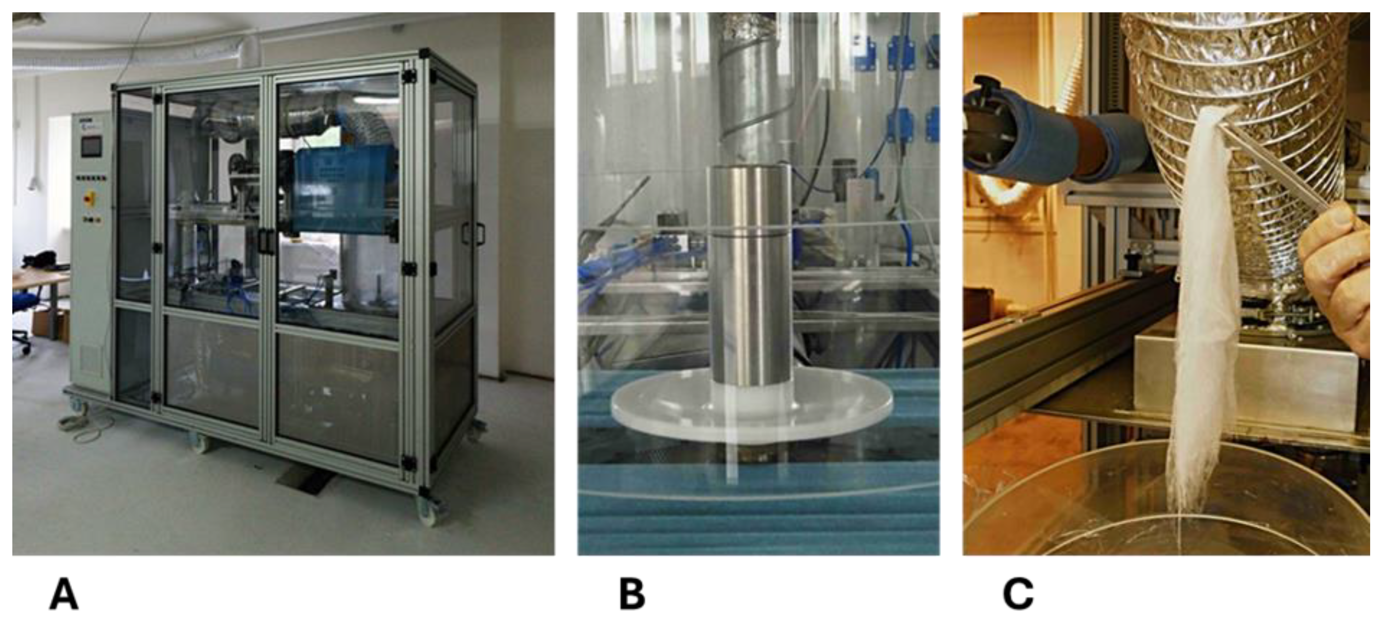
Figure 2.
SEM images of the 3D fiber „cotton wool-like constructs“ prepared from the single polymers. Scale bars 100 µm. SEM microscope: Phenom G2.
Figure 2.
SEM images of the 3D fiber „cotton wool-like constructs“ prepared from the single polymers. Scale bars 100 µm. SEM microscope: Phenom G2.
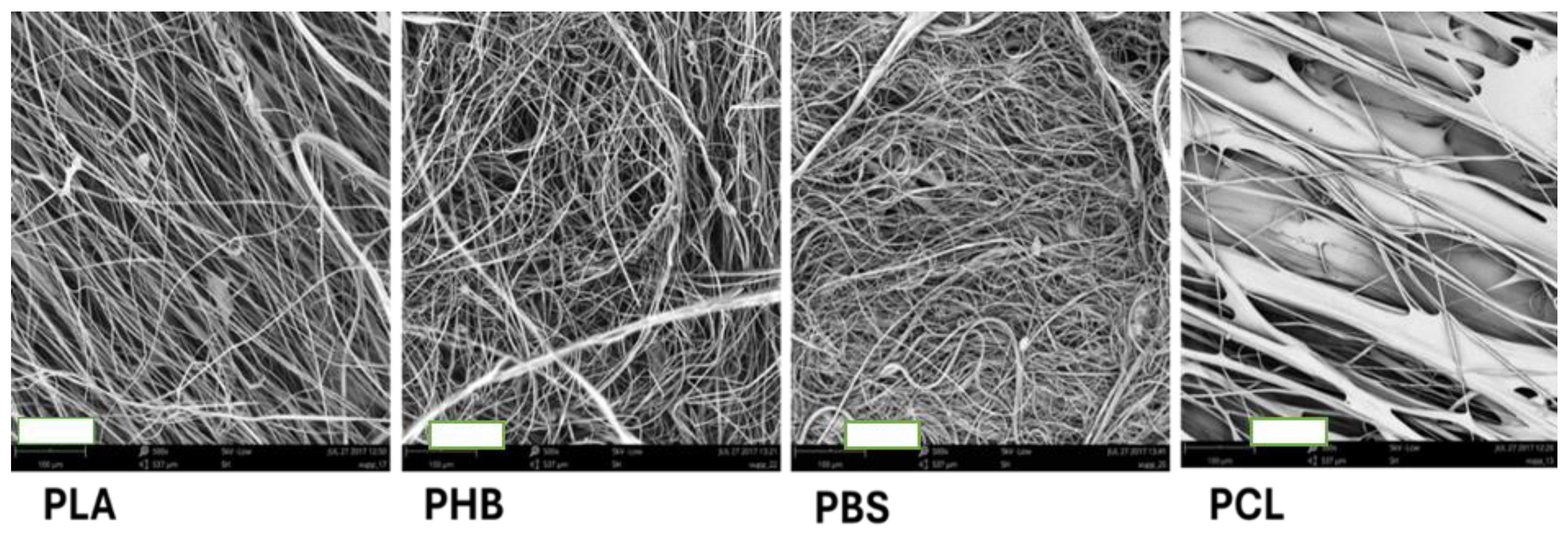
Figure 3.
SEM images of 3D fiber „cotton wool-like constructs“ prepared from PHB/PLA blend, weight ratio 4/1. Scale bars 100 µm (A), 50 µm (B), 10 µm (C). SEM microscope: Phenom G2.
Figure 3.
SEM images of 3D fiber „cotton wool-like constructs“ prepared from PHB/PLA blend, weight ratio 4/1. Scale bars 100 µm (A), 50 µm (B), 10 µm (C). SEM microscope: Phenom G2.
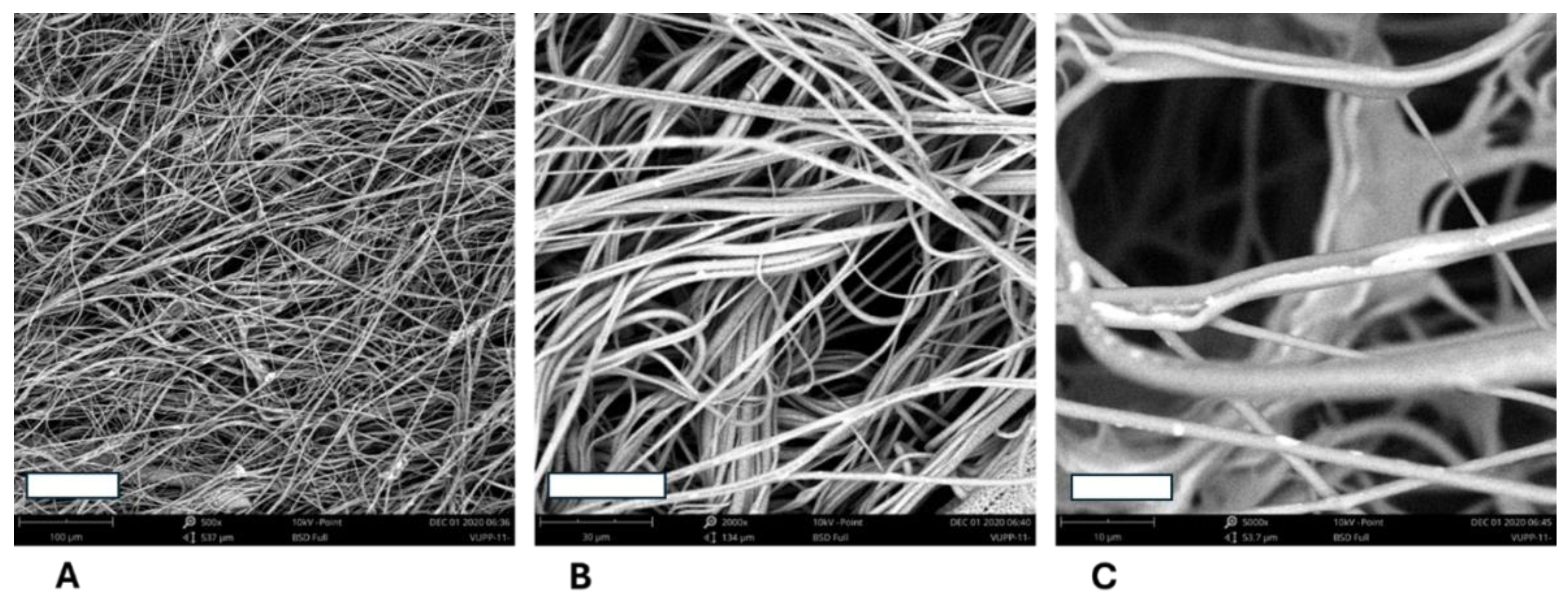
Figure 4.
SEM images of 3D fiber „cotton wool-like constructs“ prepared from PHB/PBS blend, weight ratio 1/4 (A-C) or 2/7 (D-F). Scale bars 100 µm (A, D), 50 µm (B, E), 20 µm (C, F). SEM microscope: FIB-SEM, LYRA3 GMU, Tescan.
Figure 4.
SEM images of 3D fiber „cotton wool-like constructs“ prepared from PHB/PBS blend, weight ratio 1/4 (A-C) or 2/7 (D-F). Scale bars 100 µm (A, D), 50 µm (B, E), 20 µm (C, F). SEM microscope: FIB-SEM, LYRA3 GMU, Tescan.
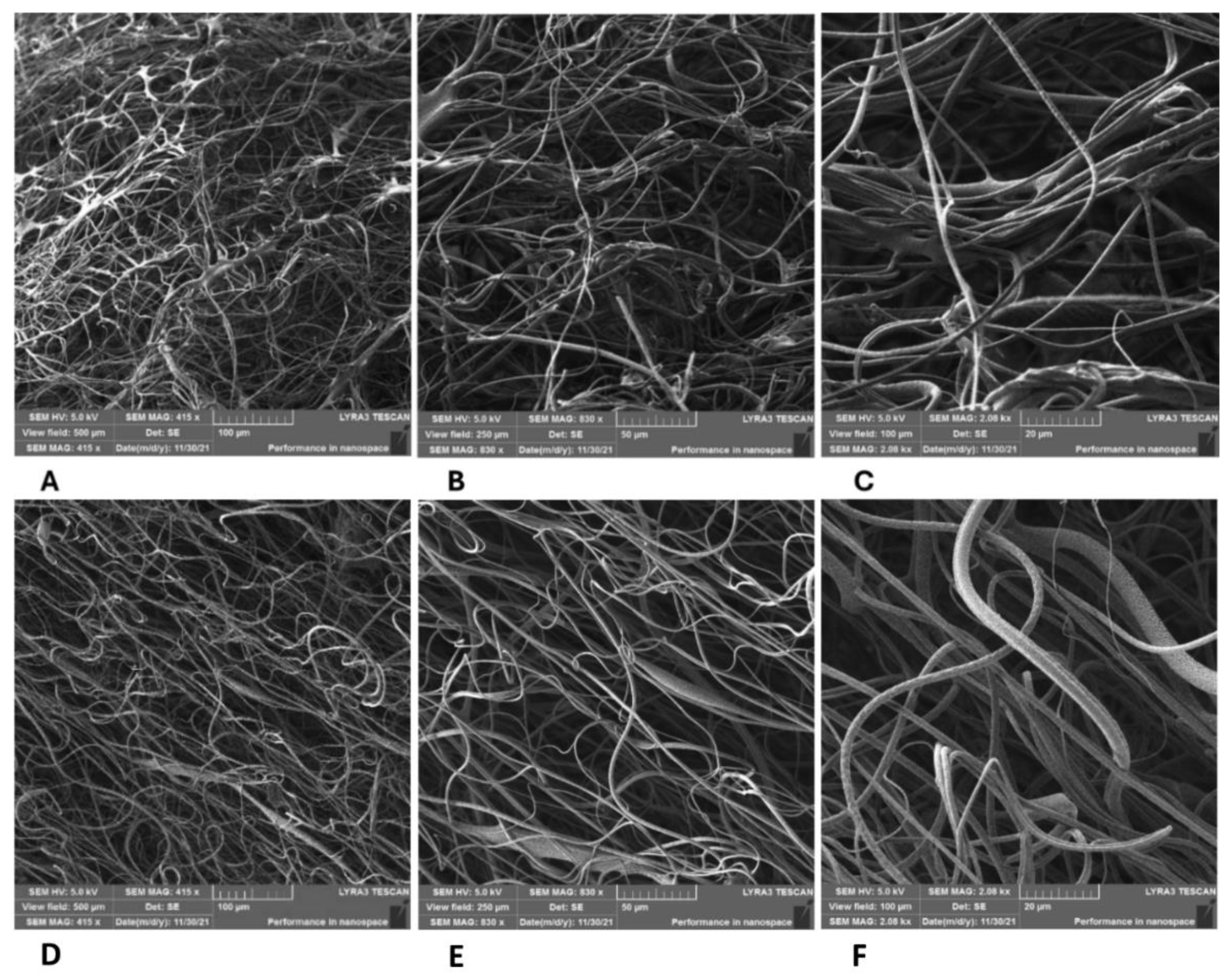
Figure 5.
SEM images of 3D fiber „cotton wool-like constructs“ prepared from PLA/PCL blend, weight ratio 5/1, disk rotation speed 1500 rpm. Scale bars 100 µm (A), 30 µm (B), 10 µm (C). SEM microscope: Phenom G2.
Figure 5.
SEM images of 3D fiber „cotton wool-like constructs“ prepared from PLA/PCL blend, weight ratio 5/1, disk rotation speed 1500 rpm. Scale bars 100 µm (A), 30 µm (B), 10 µm (C). SEM microscope: Phenom G2.
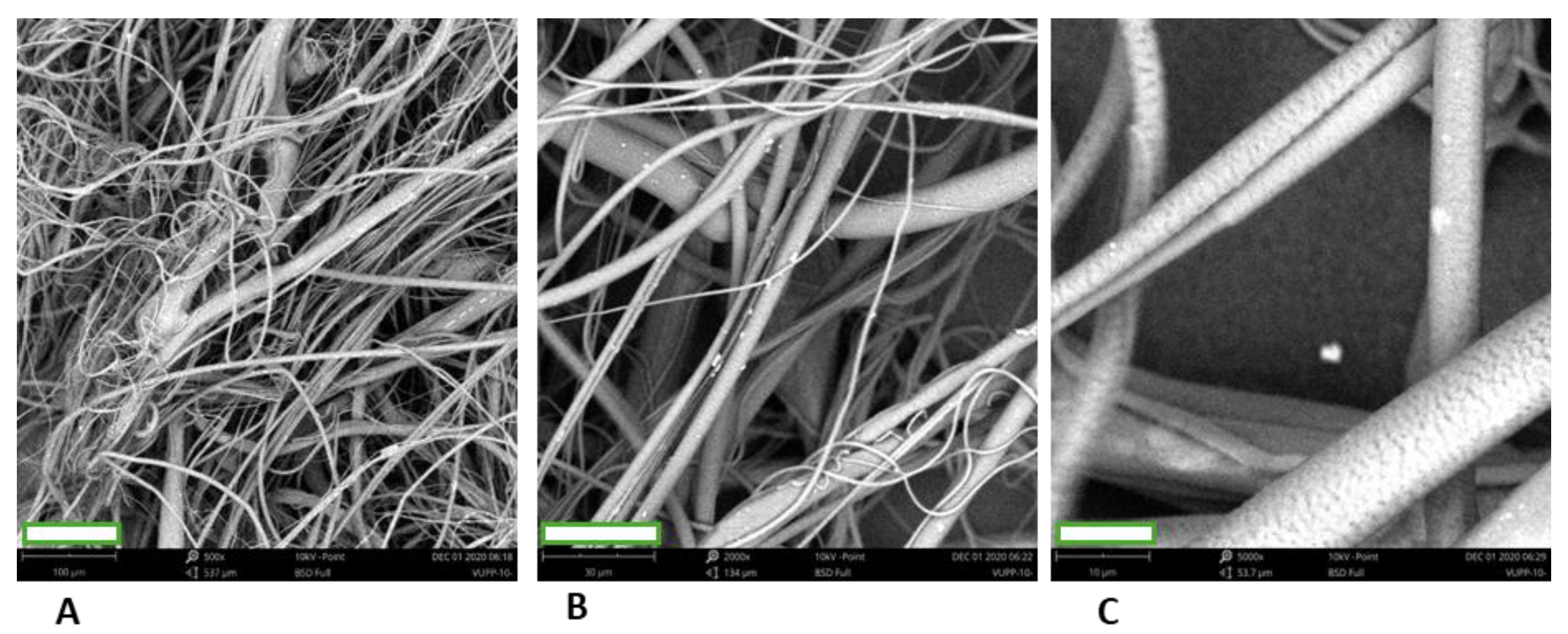
Figure 6.
SEM image of 3D fiber „cotton wool-like constructs“ prepared from PLA/PCL blend, weight ratio 13.5/4, disk rotation speed 1500 rpm (A, B), 3000 rpm (C, D) or 5000 rpm (E, F). Scale bars 100 µm (A, C, E), B 50 µm (B, D, F). SEM microscope: FIB-SEM, LYRA3 GMU, Tescan.
Figure 6.
SEM image of 3D fiber „cotton wool-like constructs“ prepared from PLA/PCL blend, weight ratio 13.5/4, disk rotation speed 1500 rpm (A, B), 3000 rpm (C, D) or 5000 rpm (E, F). Scale bars 100 µm (A, C, E), B 50 µm (B, D, F). SEM microscope: FIB-SEM, LYRA3 GMU, Tescan.
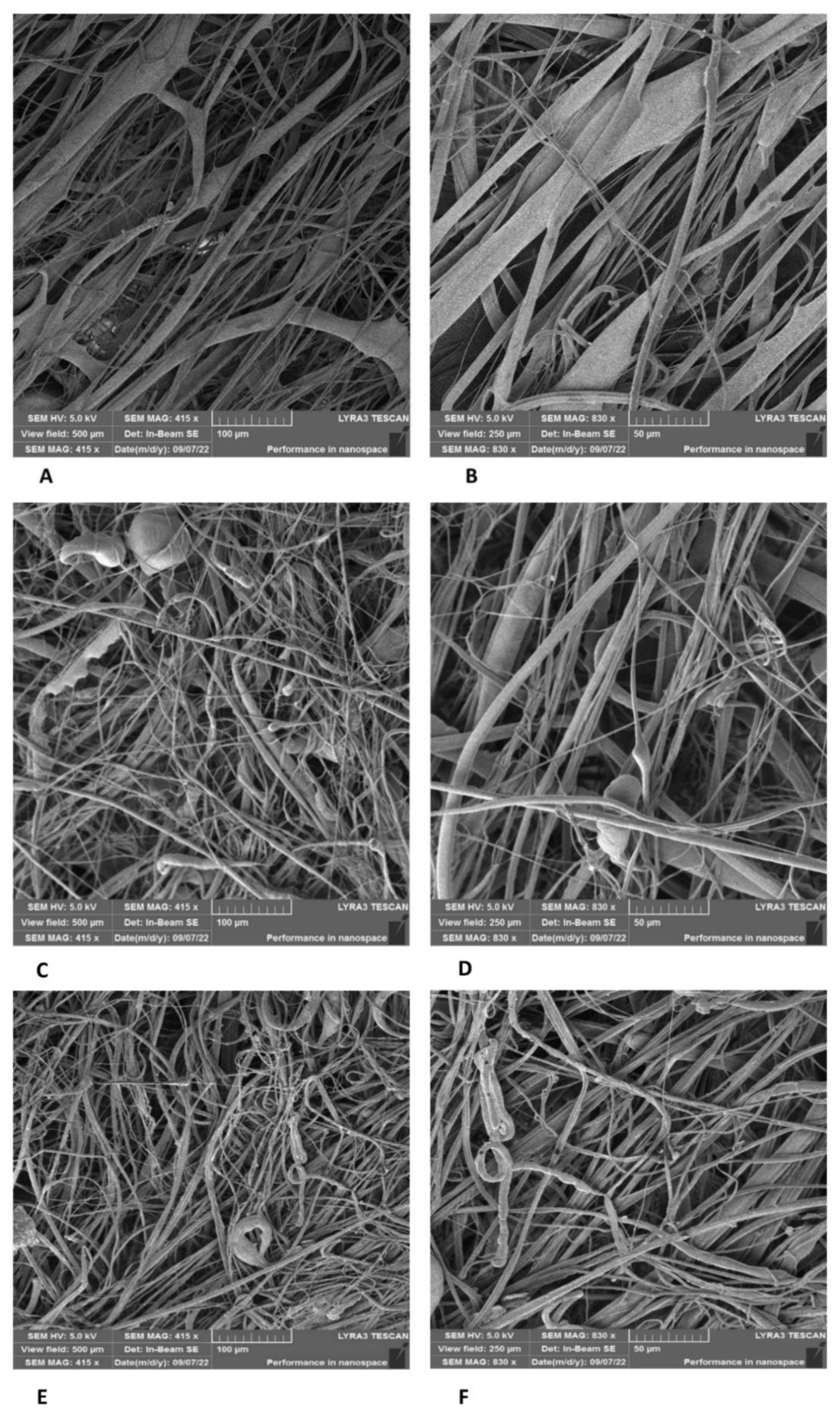
Figure 7.
SEM image of a fiber of the „cotton wool-like constructs“ prepared from PLA/PCL blend, weight ratio 13.5/4 - a fiber detail. SEM microscope: FIB-SEM, LYRA3 GMU, Tescan.
Figure 7.
SEM image of a fiber of the „cotton wool-like constructs“ prepared from PLA/PCL blend, weight ratio 13.5/4 - a fiber detail. SEM microscope: FIB-SEM, LYRA3 GMU, Tescan.
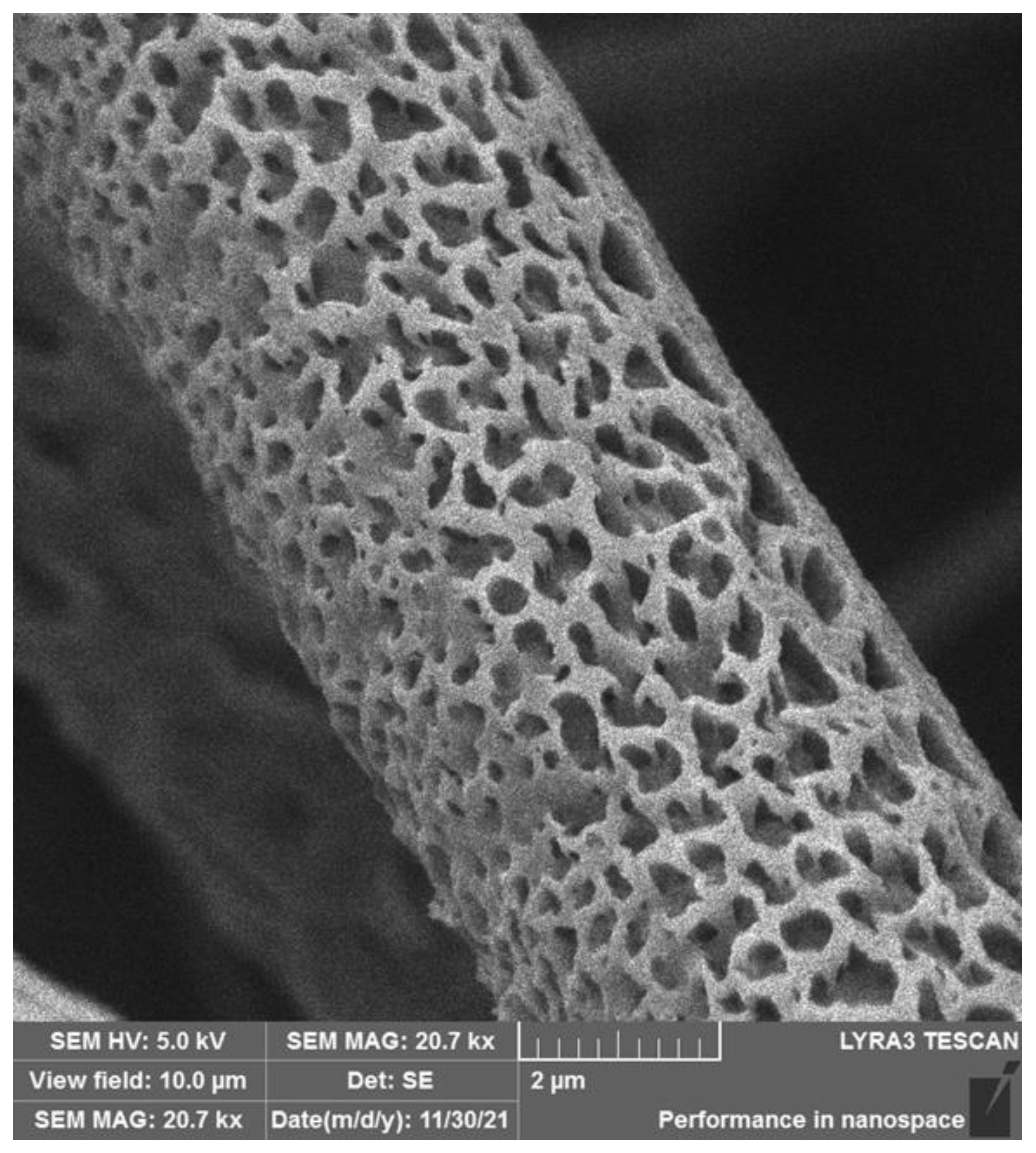
Figure 8.
Results of BET analysis of the micro/nanofibrous hybrid scaffolds prepared from the 5/1 and 13.5/4 (w/w) PLA/PCL blends: pore size distribution histograms.
Figure 8.
Results of BET analysis of the micro/nanofibrous hybrid scaffolds prepared from the 5/1 and 13.5/4 (w/w) PLA/PCL blends: pore size distribution histograms.
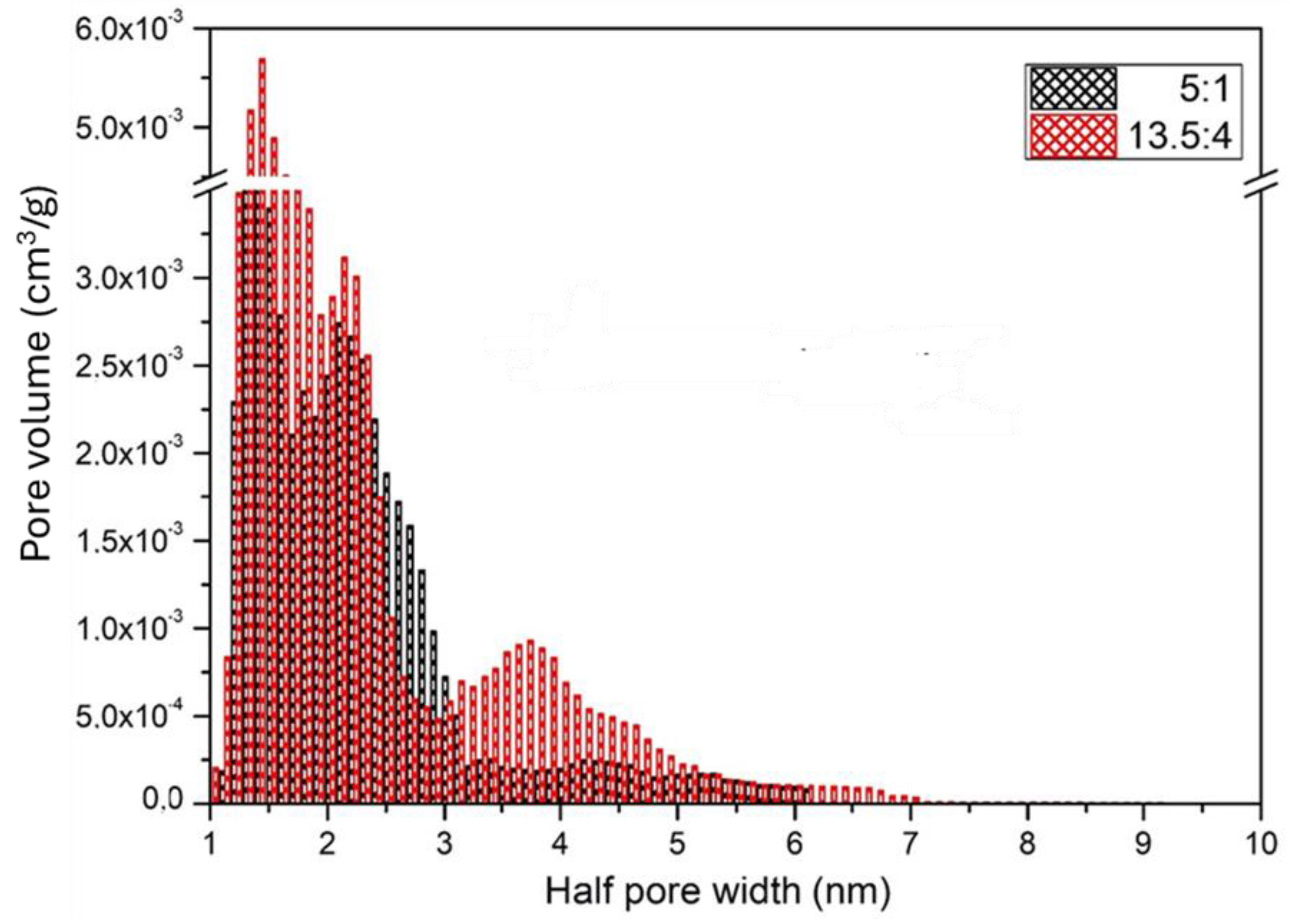
Figure 9.
Results of BET analysis of the micro/nanofibrous hybrid scaffolds prepared from the 5/1 and 13.5/4 (w/w) PLA/PCL blends: nitrogen adsorption and desorption isotherms.
Figure 9.
Results of BET analysis of the micro/nanofibrous hybrid scaffolds prepared from the 5/1 and 13.5/4 (w/w) PLA/PCL blends: nitrogen adsorption and desorption isotherms.
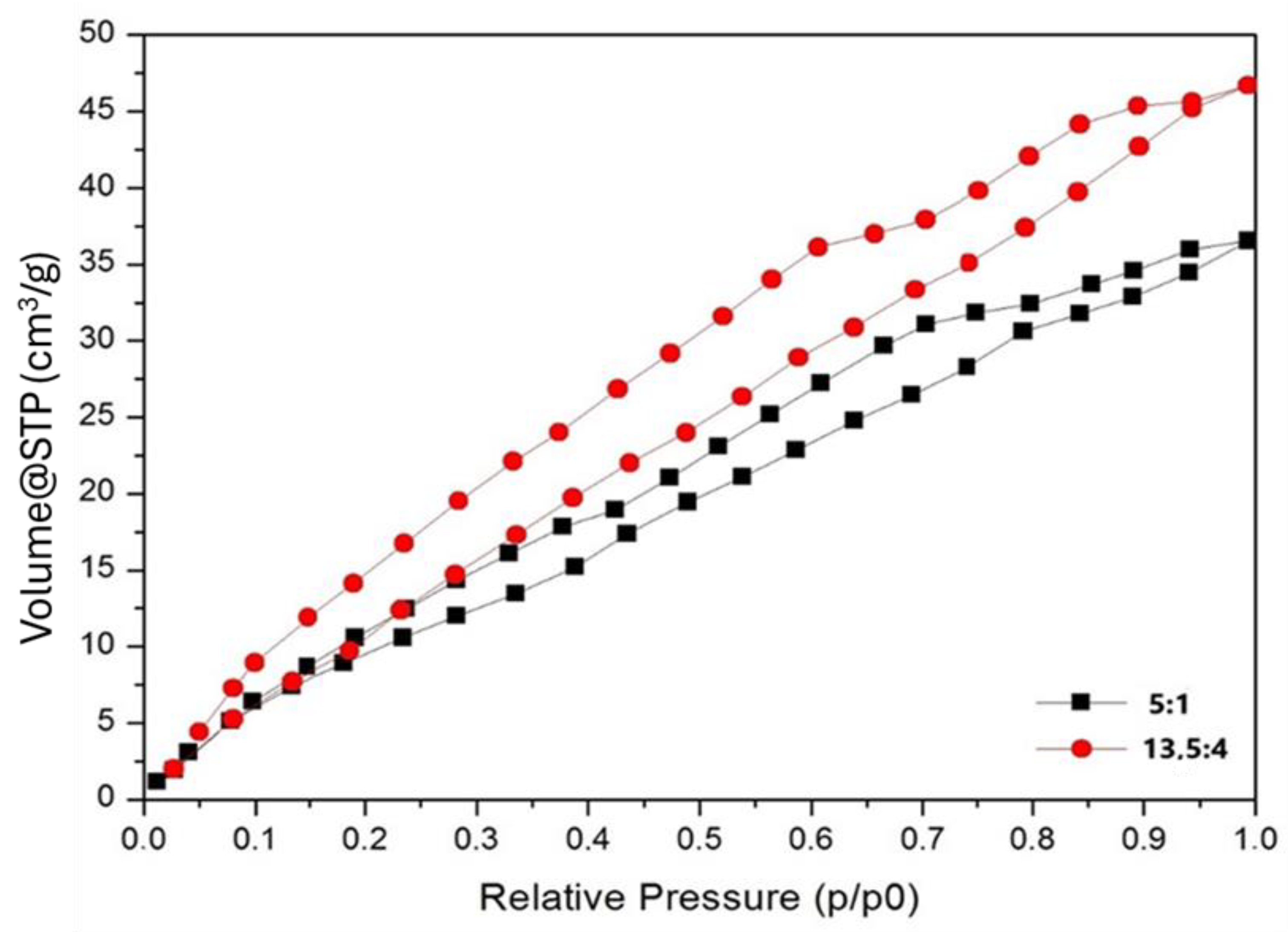
Figure 10.
ASC colonization of nanofibrous scaffolds composed of PLA (A), PLA/PHB 4/1 w/w (B) and PLA/PCL 13.5/4 (w/w) (C) on day 10 after seeding. Fluorescence staining of F-actin in cells with phalloidin (red), cell nuclei counterstained with DAPI (blue). Images were taken either from the top of the scaffolds or as a 3D side view. Andor Dragonfly 503 confocal microscope, obj. 20x, scale bars 150 µm. .
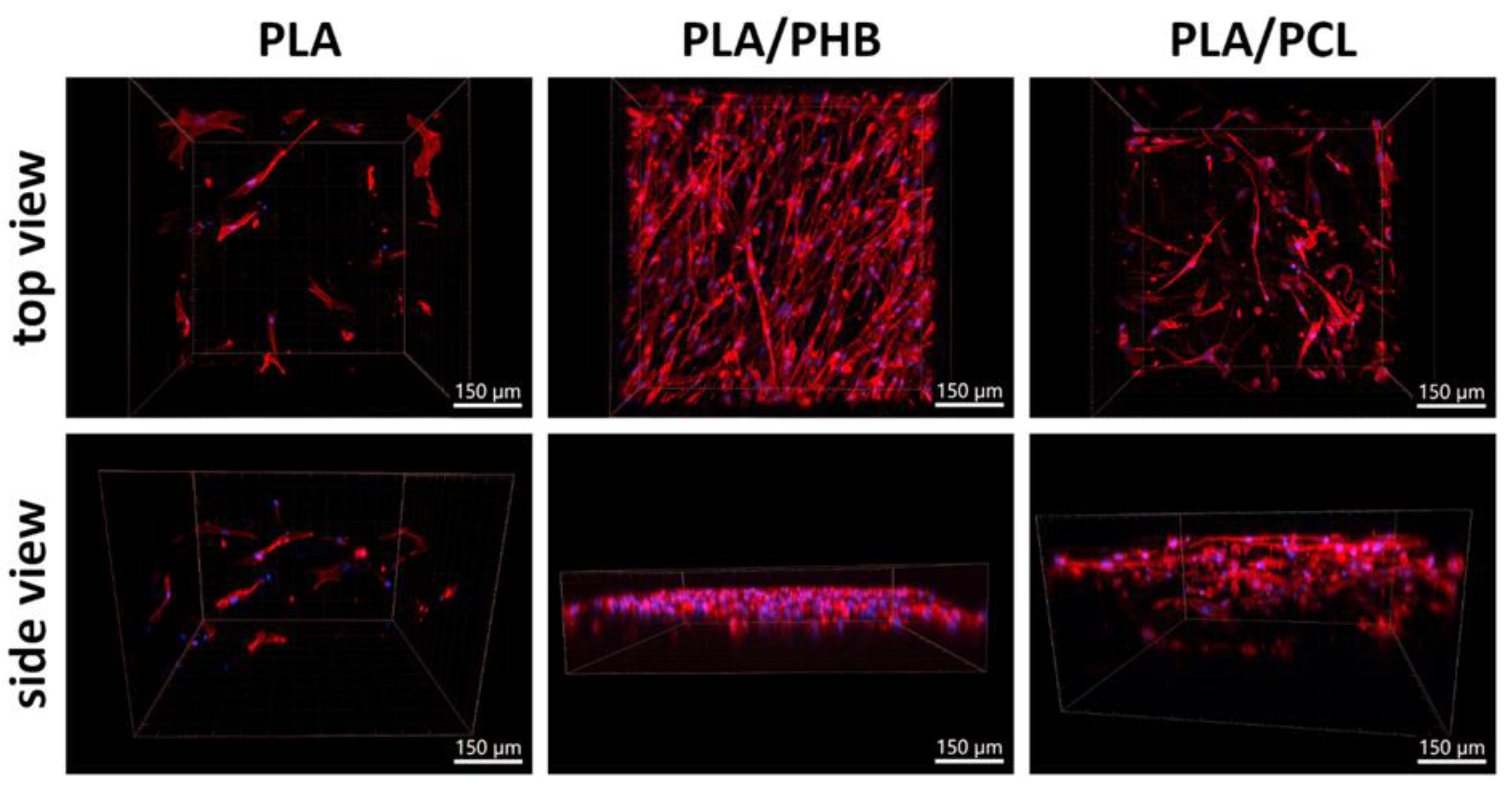
Figure 11.
The penetration depth of ASCs in PLA/PCL 13.5/4 (w/w) micro/nanofibrous hybrid scaffolds on days 2, 6 and 10 after cell seeding. Fluorescence staining of F-actin in cells with phalloidin (red), nuclei counterstained with DAPI (blue). Images were taken as 3D side views. Andor Dragonfly 503 confocal microscope, obj. 20x, scale bar 150 µm.
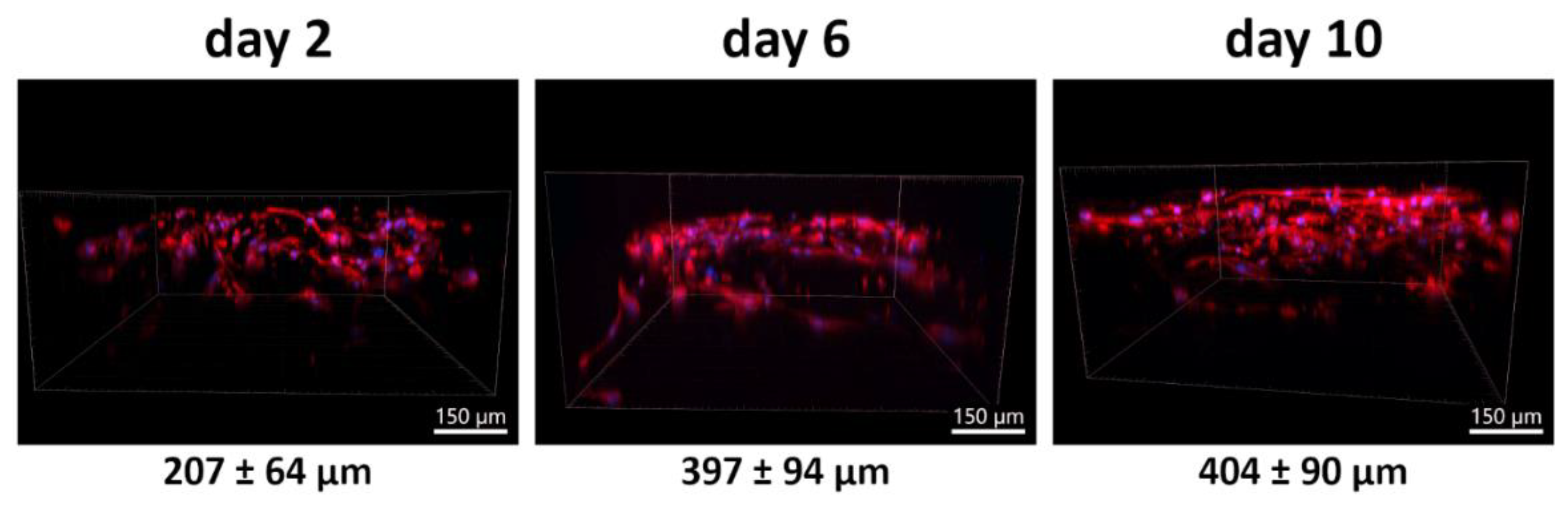
Figure 12.
Morphology of ASCs on the PLA/PCL 13,5/4 (w/w) micro/nanofibrous hybrid scaffolds on day 6 after cell seeding. Actin filaments - phalloidin (red), cell nuclei - DAPI (blue). Andor Dragonfly 503 confocal microscope, obj. 20x, zoom 2x, scale bars 50 µm. .
Figure 12.
Morphology of ASCs on the PLA/PCL 13,5/4 (w/w) micro/nanofibrous hybrid scaffolds on day 6 after cell seeding. Actin filaments - phalloidin (red), cell nuclei - DAPI (blue). Andor Dragonfly 503 confocal microscope, obj. 20x, zoom 2x, scale bars 50 µm. .
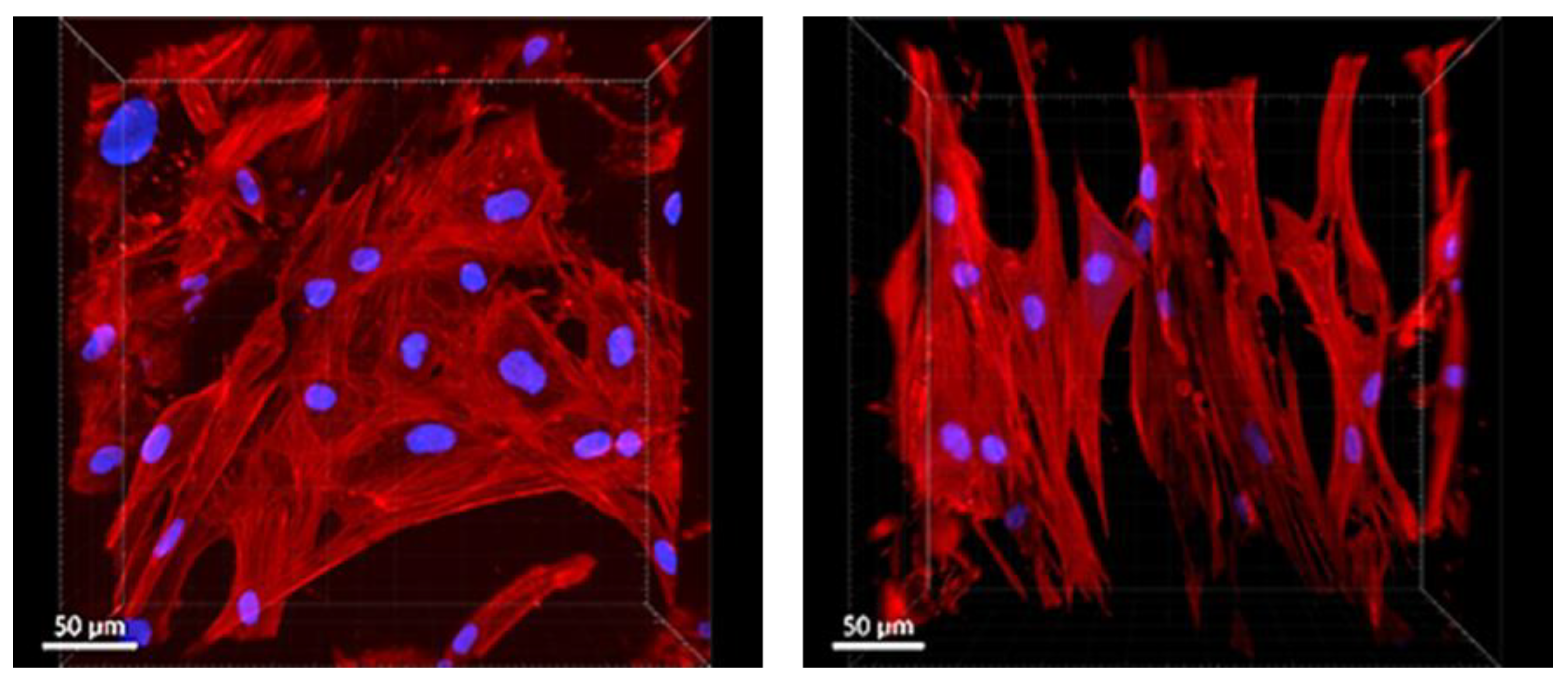
Figure 13.
Colonization of PLA/PCL 13.5/4 (w/w) micro/nanofibrous hybrid scaffolds with ASCs on days 2, 6 and 10 of cultivation in an adipogenic medium. Fluorescence staining of F-actin in cells with phalloidin (red), nuclei counterstained with DAPI (blue). Images were taken either from the top of the scaffolds or as a 3D side view. Andor Dragonfly 503 confocal microscope, obj. 20x, scale bars 100 µm. .
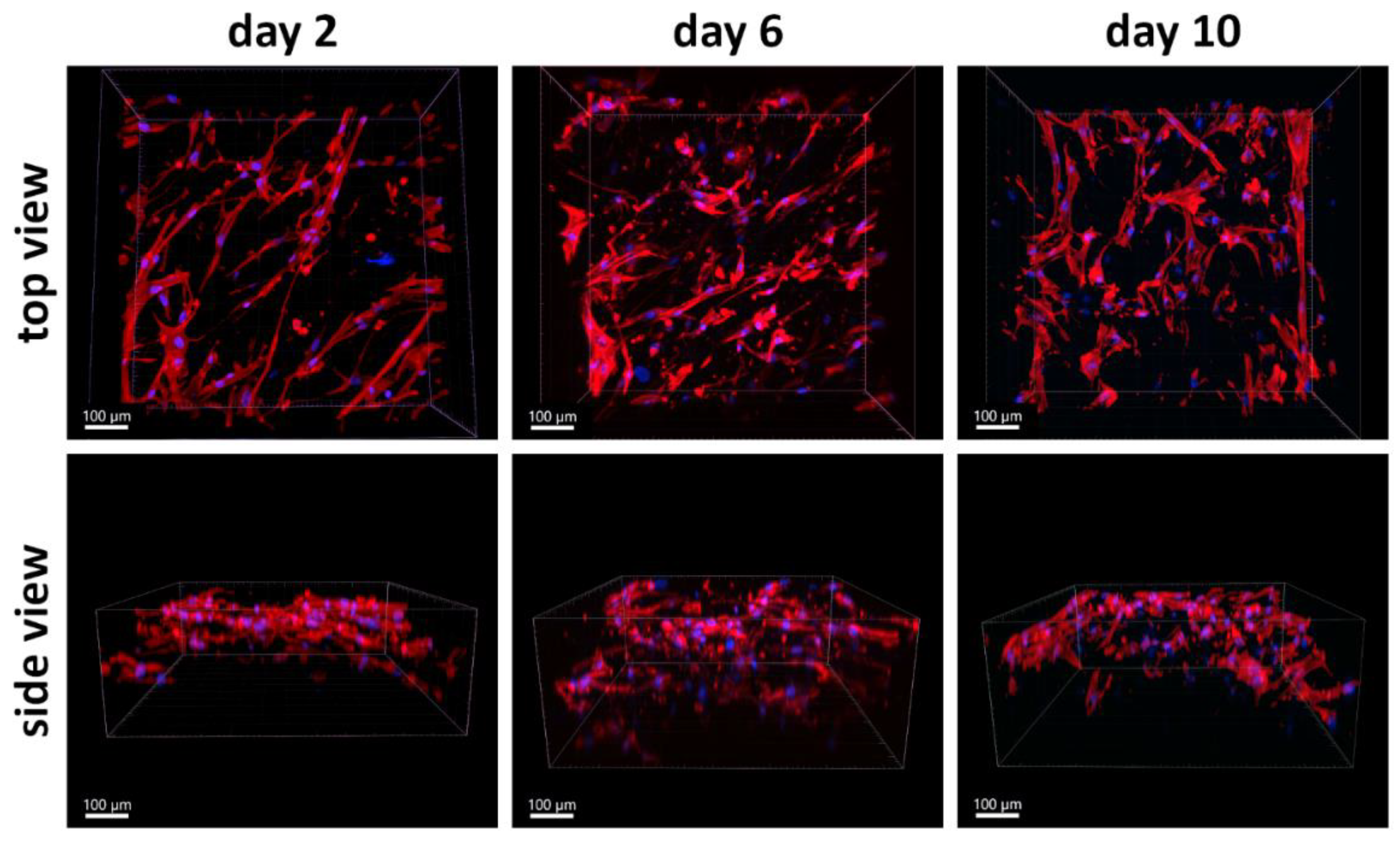

Table 1.
Parameters of the centrifugal spinning of single polymers and polymer mixtures using the Nanocent demonstrator.
Table 1.
Parameters of the centrifugal spinning of single polymers and polymer mixtures using the Nanocent demonstrator.
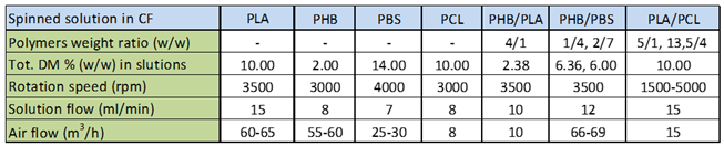 |
Table 2.
Results of BET analysis of the micro/nanofibrous hybrid fiber biodegradable scaffolds.
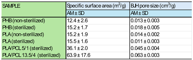 |
Table 3.
The maximum thickness of the layer into which cells migrated on different types of scaffolds (measured using Andor Dragonfly 503 scanning disc confocal microscope in 2-3 samples for each experimental group).
Table 3.
The maximum thickness of the layer into which cells migrated on different types of scaffolds (measured using Andor Dragonfly 503 scanning disc confocal microscope in 2-3 samples for each experimental group).
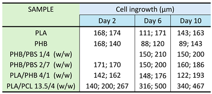 |
Disclaimer/Publisher’s Note: The statements, opinions and data contained in all publications are solely those of the individual author(s) and contributor(s) and not of MDPI and/or the editor(s). MDPI and/or the editor(s) disclaim responsibility for any injury to people or property resulting from any ideas, methods, instructions or products referred to in the content. |
© 2024 by the authors. Licensee MDPI, Basel, Switzerland. This article is an open access article distributed under the terms and conditions of the Creative Commons Attribution (CC BY) license (http://creativecommons.org/licenses/by/4.0/).
Copyright: This open access article is published under a Creative Commons CC BY 4.0 license, which permit the free download, distribution, and reuse, provided that the author and preprint are cited in any reuse.


