
Submitted:
20 December 2024
Posted:
23 December 2024
You are already at the latest version
Abstract
Proton membrane exchange fuel cells (PEMFCs) is an important energy solution to decarbonizing transport sectors and electric systems due to zero carbon emission during the operating process, and how to enhance the system efficiency of PEMFC is one of the most challengeable issues to hinder the large-scale commercial application of PEMFC. In recent years, numerous studies have been conducted to explore the feasibility and techno-economic performance of advanced thermal management to promote the efficiency of PEMFC systems. The thermal management of PEMFC can be implemented from two aspects: one is efficient cooling methods to maintain the PEMFC under proper working temperature range, and the other one is waste heat recovery from PEMFC and improve the overall system efficiency. Concentrated on these topics many achievements have been gained by academic and industrial communities, and it is imperative to analyze and conclude these experienced studies from mechanism, technology and application aspects. Therefore, this review summarized the great advances of thermal management of PEMFC from efficient cooling and waste heat recovery for the sake of improving the overall efficiency of PEMFC systems, providing guidelines for the future design and optimization of PEMFC systems.
Keywords:
Proton exchange membrane fuel cells
; thermal management
; system efficiency
; cooling methods
; waste heat recovery
1. Introduction
Proton exchange membrane fuel cells (PEMFC) have the advantage of low operating temperature, high reliability with quick startup response, which make it a promising candidate for vehicle applications [1,2,3]. PEMFCs are garnering significant attention as a promising solution for the transportation electrification as shown in Figure 1, due to higher power density and shorter refueling durations compared to conventional electric battery systems [4,5,6]. One of the most important performance indicators for PEMFC is thermal efficiency. From year 2010 to 2020 measured system efficiency of the worldwide PEMFC passenger vehicle has increased from 35% to 60% under specific testing driving cycle [7,8]. The latest target efficiency of heavy-duty truck is set to 68% till 2030 and 72% for ultimate target by America DOE [9]. Therefore, there is still long way to improve the thermal efficiency of PEMFC to propel the commercialization process [10].
A PEMFC system is composed of the fuel cell stack and the balance of plant (BOP): the former converts the chemical energy of hydrogen into electricity, while the latter supplies the reactants and ensures the expected reaction boundary conditions for the electrochemical reaction [11,12]. Since it appeared in public, research on improving fuel cell efficiency from stack design and material definition side has never stopped, and these works conclude the optimizing catalysts in MEA to improve the electrochemical reactions kinetic [13,14,15] , developing novel membrane with high proton conductivity and low electrical resistance [16], using metal gas diffusion layer (GDL) with lower contact resistance between bipolar plate (BP) and GDL [17], water management [18], and designing flow fields to minimize the flow resistance both for reactant gas and cooling system [12]. Meanwhile, there are operation-oriented solutions to increase fuel cell’s the system efficiency of PEMFC which calls for elaborate effort from vehicle side, including the adjustment of PEMFC operation parameters like temperature [19,20], pressure[21], and reactant stoichiometry ratio [19], decrease of parasitic power of air boosting system from control side [22], improvement of water removal methods [23], modification of system topology by integrating the fuel cell system with energy storage systems [11,24], and incorporating new energy management strategy [25]. Though significant improvement in fuel cell performance have been achieved through basic and technically solutions over the past decades, cost and reliability remains as the challenge for its commercialization [26,27]. Continuous increase of system efficiency becomes even more urgent to decrease the fuel cell stack’s product cost and usage cost.
Compared with the efficiency improvement from component side, system-level solutions get more and more attention in recent years which calls for intensive research into the interaction among components (hardware), material property, control strategy and operation environment optimization in system implementation level [28,29,30,31]. Around 30~50% of hydrogen's chemical energy is converted into heat during the electrochemical reaction process inside the PEMFC [32,33]. Effective thermal management is indispensable to control the working temperature in a stable range for safe and efficient operation of PEMFC [34]. Thermal management system stands among the quartet of pivotal subsystems that require precise operation and control to optimize fuel cell system performance [35]. The thermal management of PEMFC includes two aspects. On the one hand, proper cooling methods are incorporated to maintain PEMFC under proper temperature range for higher working efficiency. On the other hand, recovering waste heat from the exhaust gas and cooling water to enhance the overall efficiency of PEMFC systems.
This review aims to analyze the progress of thermal management of PEMFC related to the improvement of thermal efficiency from mechanisms to applications. The structure of this review is organized as follows: after the background introduction, in Section 2a brief introduction to the working principles of the PEMFC is presented, along with its associated voltage and efficiency model, which serves as the criteria and basis for the following work. Section 3 summaries efficiency improvement from cooling methods, after a detailed comparison analysis between liquid cooling and phase changing cooling, the former is chosen as the main solution out of consideration of weight, volume, cost, compatibility and cold start performance. covering and cooling strategy. Subsequently, the latest developments in the optimal operating temperature setting and control, temperature uniformity and consistency control, and parasitic power optimization are further stated. Section 4 introduces waste heat recovery from the cooling system, as 80% of the generated heat needs to be dissipated by the cooling system. In addition to thermodynamic cycles, typical topologies and achievements of waste heat recovery methods, such as combined heat, cooling, and power, are reviewed in detail to clarify a clear path. In the conclusion section, a technical roadmap for efficiency enhancement is proposed, along with the future development trend.
2. Working Principle of PEMFC
A fuel cell is a kind of electrochemical device that can convert chemical energy into electric power. As schematically shown in Figure 2 [12], a single PEMFC consists of a proton-conductive membrane in middle, electrodes and platinum catalyst layer (CL) coated, MPL micro-porous layer, sometimes not used, gas diffusion layer (GDL) and bipolar plates in both anode and cathode, where the sandwiched membrane and anodes is also called membrane electrode assembly (MEA). The fuel cell completes the following functions: passages for species and heat transport and electronic connection between the bipolar plates and catalyst layers. According to the literature, the oxygen reduction reaction (ORR) at the cathode CL releases the most heat during normal operation [36] ,so coolant channel usually lay inside the BP near the cathode side.
2.1. Voltage Model
The working process of fuel cell is a controlled electrochemical reaction with simultaneous production of electricity, water and heat. Theoretically the fuel cell efficiency can be inferenced through its output voltage.
At Anode, the hydrogen is decomposed into protons and electrons in the catalyst layer of the anode to trigger hydrogen oxidation reaction (HOR). At Cathode, the protons migrate through the PEM to the cathode to combine with oxygen to trigger oxygen reduction reaction (ORR).At standard temperature and pressure condition , with the product water in liquid phase, the total enthalpy change of the above thermodynamic process is: : -286kJ/mol, Gibbs free-energy change during the process is : : -237.3kJ/mol, so the maximum thermos efficiency of the system is:
The reversible voltage under ideal temperature and pressure condition can be calculated [27,37,38] as Equation (2)
Where n is number of moles of electrons transferred, n=2 in this case, and F is Faraday's constant, F=96845).
The Nernst equation for this reaction under real pressure and activities can be written as Equation (3) [39]
If the fuel cell is operated below 100°C, so that liquid water is produced, the activity of water is set to unity . Activities of hydrogen and oxygen gases is replaced by their unitless partial pressures . Nernst equation for this reaction under real temperature, pressure and activities can be expressed further as:
The entropy of the reaction may differ depending on the mixing phase of liquid, gas H2O in reaction product the coefficient of the temperature effect ranges from [39,40,41]. For high temperature PEMFC, the coefficient gets even lower, so higher voltage will gets higher [42]. According to Equation (4) reversible output voltage decrease as the reaction temperature increase.
As depicted in Figure 3, the output voltage of fuel cell is lower than reversible voltage due to polarization loss: in the low current density area, activation loss is the dominant one. With the output current density increases, ohmic loss due to ionic and electrical transfer activation loss cause the output voltage to decrease further. In the high current density area, concentration loss becomes dominant.
Referring to power density distribution as depicted in Figure 3, highest power density of the fuel cell located in the medium to high current density area, for real vehicle application, high power density is desired which makes the activation loss and ohmic loss unavoidable in real vehicle operation. The fuel cell output is expressed as [43].
Where:
: activation losses due to reaction kinetics, generally it could be described by the
Butler–Volmer equation or the simpler Tafel equation.
: ohmic losses from charger transport, e.g. ionic and electronic resistance
: concentration losses due to mass transport of reactants and products inside a fuel
cell stack.
As shown in Figure 3, under medium to high load conditions, which represent the typical operating range for FCEVs, the output voltage of a single fuel cell is generally in the range of 0.6~0.7 volts. To meet the specific high drive voltage requirement for vehicle operation, hundreds of fuel cells are electrically connected in series through bipolar plates, which inevitably leads to an increase in cost and space.
2.2. Efficiency Model
The final output efficiency of a fuel cell stack is less than the reversible thermodynamic efficiency due to the voltage losses and fuel utilization losses. Real efficiency of a fuel cell can be expressed as:
Where is the reversible thermodynamic efficiency of the fuel cell as defined in Equation (1), is the fuel utilization efficiency of the fuel cell, is the voltage efficiency of the fuel cell, is the real operating voltage of the fuel cell; is thermodynamically reversible voltage of the fuel cell as defined in Equation (2).
Equation (6) represents the classical way to describe fuel cell efficiency, and it’s helpful to identify the contribution for efficiency improvement. For real time vehicle operation, the output of the fuel cell changes frequently even in stable working point. It’ feasible to calculate the overall efficiency in terms of energy over the driving cycle with the aid of integral method.
A typical fuel cell vehicle layout is shown in Figure 4, the core components of this layout include fuel cell stack, battery pack, drive motor, thermal and air management system, hydrogen storage system, electronic control system, which work together to meet the energy requirements and driving performance of the vehicle. The fuel cell stack efficiency is defined as the ratio of the electrical power output of the fuel cell stack to the theoretical maximum power that could be produced if all the chemical energy of the fuel were converted into electricity under ideal conditions.
Where t represents time, : fuel cell voltage and current, : hydrogen consumption rate, : higher heating value of hydrogen.
Concerning system efficiency, parasitic power consumed by BOP shall be considered, e.g. consumption of power electronics, thermal management system as well as air management. Moreover, the system efficiency also includes the recovery of waste energy and it can be expressed as:
A comprehensive technology assessment measurement of fuel cell stack efficiency and system efficiency referring to Equation (7), (8) was conducted by America DOE through a 2016 Toyota Mirai. It was tested at varied steady-state vehicle speed and load with in-depth instrumentation to create the efficiency map across the whole power level in a controlled test environment. As shown in Figure 5, the measured peak fuel stack efficiency, system efficiency is 66.0% and 63.7% separately. The continuous maximum power is 72 kW, the maximum fuel cell stack output power is 110-114 kW and the maximum fuel cell system output power is 92 kW with a system efficiency around 40%. As the output power increases, the decrease in system efficiency is significant. For commercial vehicles that typically operate in the medium to high load range, this issue will be particularly prominent with increase in hydrogen consumption. The problem can be mitigated by shifting the fuel cell load region as far left as possible by increasing the number of cells, but this will lead to purchase cost increase for end user. The increase in system efficiency will lead to a reduction in both purchase and usage costs.
3. Efficiency Improvement of PEMFC by Efficient Cooling
Around 30~50% of hydrogen's chemical energy is converted into heat during electrochemical reaction process inside PEMFC [32,33], thermal management system is vital to guarantee fuel cell’s proper work. The object of stack thermal management systems is to control the working temperature in a stable range with minimum temperature deviation throughout the stack and minimum parasitic loss.
3.1. Demonstrations of Cooling Methods in PEMFC
There are various cooling methods investigated for the thermal management of PEMFC, including air cooling, liquid cooling and phase change cooling [47]. Given the limitations inherent in air cooling concerning their efficacy and spaces, air cooling methods are not deemed suitable for high-power PEMFC in vehicular applications. The liquid cooling is the most commonly used cooling method in PEMFC, while phase change cooling indicates great potential due to the increasing power density of PEMFC. Phase change cooling methods include various modes such as evaporation and boiling cooling of liquid working fluids and melting/solidification of phase change materials. In some research, heat pipe cooling is also treated as kind of phase change cooling [48]. The flow boiling cooling process characterized by the heated liquid rapidly transform into vapor throughout its volume, the saturation temperature of coolant is approximately 10~ 20 K lower than the optimum PEM stack operating temperature [49].
For stationary applications, the size and weight of a cooling system may not be a critical issue. However, for vehicle application, where space and weight are always challenge. A comprehensive evaluation must be carried out during the early phase to balance the space, weight, cost and heat rejection ability of the cooling system as well as its parasitic power. Liquid cooling method has high power cooling ability, flexible controlled cooling ability and it’s also efficient in heat recovery, liquid cooling is the suitable cooling method for FCEVs [50]. When the fuel cell stack power goes higher above 5 kW, liquid cooling shows its advance in lower parasitic power than air cooling; higher cooling capacity than phase change cooling [51]. For cold start, a critical function in vehicular applications in low temperature environment, by circulating the cooling fluids through the fuel cell stack, the ice formation within the PEMFC can be mitigated, thereby facilitating a smoother startup process [52,53]. Liquid cooling shows its unique in convenience of integrating other cooling system in FCEVs. Due to its maturity, the liquid cooling methods have been highly considered by industrial companies, especially from the component level to achieve the cooling performance. Honda applied wave flow channel separator inside the fuel stack to enhance cooling efficiency for FCX clarity, the uniform cooling of the generating surfaces achieved by this method has enabled the number of cooling layers required for each cell to be reduced by 1/2 [8]. In order to maximize the performance of the Mirai fuel cell stack, precise temperature control over the vehicle operation load range is realized with the aid of a water control valve. The Toyota Mirai is equipped with a cooling water control valve (electromagnetic three-way valve) The cooling water control valve is specifically designed to distribute cooling water amount between the radiator side and the bypass side [54].
Lots of research on phase change cooling have been carried by numerical simulation. Fly et al. [48] made a comparison study between system layout requirement for evaporative and typical liquid cooling. Due to higher heat transfer coefficients in the condensing radiator during phase change, the radiator frontal area required for an evaporative cooled system was 27% less than a conventional liquid cooled system. Also pressurizing the coolant channel facilitates the boiling temperature regulation was validated via numerical simulation by Choi et al. [55,56]. For phase change cooling, the design of cooling devices has also received sustained attention and research, e.g. flow boiling type cooling plate with multi microchannels, heat pipe in the shape of ultra-thin vapor chamber are proved to be effective in temperature uniformity control [49,57]. HFE-7100 with a boiling temperature of 61°C, is a recognized two-phase working fluid for low temperature PEMFC cooling with low temperature deviation [56,58]. There are few paper reported on experimental study on two phase cooling for fuel cell, except Garrity et al. [49,59].
Cooling methods with phase change materials (PCM) have been emerging a potential technology due to the high latent heat of PCM. Guo et al. [60] invented a heat-peak regulator via a thermal accumulator filled with phase-change material that separately exchanges heat with the fuel cell coolant and the air conditioner refrigerant. At circumstance temperature of 38°C, the maximum temperature of the fuel cell stack running can be reduced from 89°C to 83°C under a defined cycle, which shows its potential in reducing the parasitic power in the cooling system. PCM-based phase change cooling can also be combined with other cooling methods. Chen et al. [61] proposed a delayed liquid cooling strategy in a hybrid battery thermal management system (TMS) combined by liquid cooling and phase change materials (PCM), which reduces cooling power consumption by 33.3% without sacrificing the cooling performance. James et al. [62] studied the potential of a hybrid PCM/liquid cooling system fuel cell powered heavy-duty truck where 80% of heat rejection is dissipated by cooling fan into air, and the left 20% is dissipated by PCM. The parasitic power of fan is only 35% comparing to that 100% cooling by liquid flow. The required phase change material weighs up to 79 kg with a volume up to 97 L when the phase change material is set to carnauba wax which has the lowest mass-cost combination. PCM based thermal management system incrementally affect the weight of battery module and its cost is extremely high. In addition, most of PCMs possess very low thermal conductivity, which restricts the cooling ability used in thermal management systems.
Fan et al. [63] proves that when combined waste heat recovery from Meg watts stationary PEMFCs with cooling technique selection, liquid cooling is more suitable for places whose winter temperature is above zero for it saves cost, while phase change cooling presents better adaptivity in colder zones. For mobile application, liquid cooling method is suitable from cost, weight, volume, compatibility and cold start performance.
3.2. Control Strategies Used in Cooling Systems of PEMFC
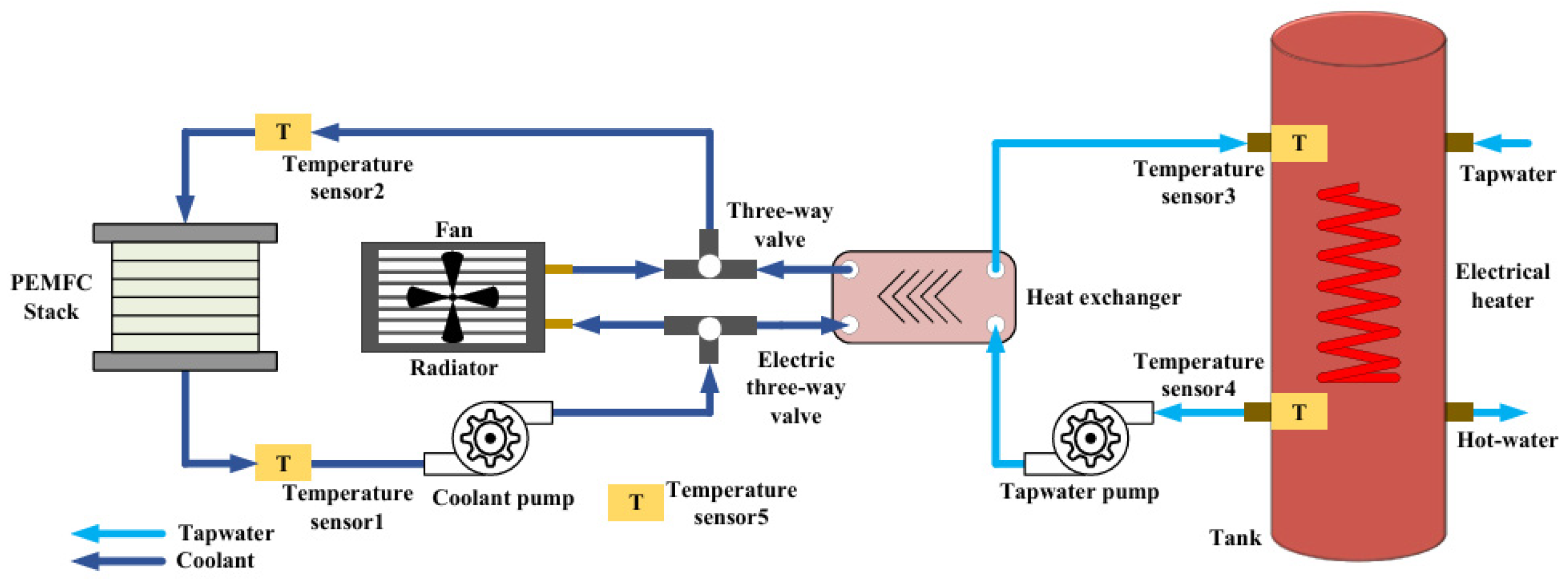
Among all the cooling methods, the liquid cooling method is widely used in commercial PEMFC. As depicted in Figure 6, a typical liquid cooling system used in PEMFC vehicles is composed of a radiator, a reservoir, a cooling pump, an electric radiator fan and a bypass valve or electric threw way vale [54,64]. The former two constitute the main sources of parasitic power in cooling system. When temperature of the outlet coolant is much lower than the upper limit value, cooling fluid can directly return to the stack back bypassing the circuit of radiator, thus saving the parasitic power consumption of circulating pump through a three-way thermostat valve [64]. A coolant control valve driven by a stepping motor can be applied instead to distribute the coolant flow circulated by coolant pump or radiator, anyhow coolant pump and radiator fan are the two indispensable heat dissipating control devices. To enhance the cooling ability, the successful implementation of cooling system also relies on proper control strategies. Significant research gaps still exist to further advance the integration of coupled TMS scheme with decoupled temperature control strategies and algorithms into high-power liquid-cooling PEMFC stack, especially for FCEVs which is frequently subjected to transient high-power thermal load variation, high durability requirements and cost constraints [65,66].
3.2.1. Optimum Control of PEMFC Temperature
The optimal operating temperature is largely dictated by mitigation of electrode “flooding”, PEM hydration, and material degradation [67]. Under conditions of low temperature, water vapor condenses into liquid water, which can accumulate within the porous structure and impede the diffusion of reactants the catalytic sites, thereby increasing the transport resistance and leading to concentration polarization of the electrodes [65,68]. Under high operation temperature, though the fuel cell reversible voltage shall decrease theoretically as Equation (3) expressed, the measured FC efficiency increase due to the enhanced electrode kinetics for the electrochemical reaction, increased membrane proton conductivity and improved mass transfer of the reactants [19,69]. But too high temperature will cause the membrane to dry out and reduces the surface area of the catalyst, which in turn weaken the stack performance [70]. The effect of temperature on the efficiency of PEMFC is demonstrated by Desantes et al. [71] through experiment, as shown in Figure 7. In this figure, it can be seen that with the increase of current load, the temperature influence increases to 3% (absolute value) at the peak load. Zhiani. et al. [69] has compared the action performance through a comparison test between low temperature (55 °C) and pressure (34 kPa) and high temperature (75 °C) and pressure (172 kPa) demonstrated the effect of temperature on activation of PEMFC and consequently the efficiency output.
There are various approaches to achieve proper working temperature of PEMFC by cooling system integrated with controller, including Linear Quadratic Integral (LQI) controllers, adaptive Linear Quadratic Regulator (LQR) controllers, fuzzy logic controllers optimized by genetic algorithms, and fuzzy PID control strategies. Sun et al. [72] proposed a multi-model predictive control method based on an adaptive switching strategy and multi object optimization, comparing to traditional PID control, model predictive control, the multi-mode predictive control model is proven to be more robust in precise temperature within a deviation within 1 K. Hu et al. [73] made a comparison among different temperature controlling strategies on hydrogen consumption including constant temperature setting, rule based temperature setting and optimal temperature tracking control. The optimal temperature tracking control can save around 25% of hydrogen consumption under CHTC-HT cycle, a China specific driving cycle for heavy duty commercial vehicle with GVW>55000kg. To save the huge experiment load for optimizing the operation temperature for each working load in vehicle driving, Tang et al. [74] developed the automatic controller calibration tool which was integrated with the dynamic model of fuel cell temperature behavior based on metaheuristic optimization algorithms and CSO-SVR model. Comparing to steady working condition, effect of temperature gets even more remarkable under dynamic conditions.
3.2.2. Temperature Uniform Control of PEMFC
Due to highly concentrated electrochemical reaction location, sandwich-like assembly, local overheating and non-uniform temperature distribution significantly contribute to the attenuation and deterioration of stack performance [65,75]. As shown in Figure 8(a), Zhang et al. [76] acquired temperature distribution in the anode/cathode flow fields a liquid cooled fuel cell stack with 5 fuel cells by three-dimensional multiphase non-isothermal modelling. Huang et al. [77] developed a thermal characteristic test platform for hydrogen fuel cells wherein the infrared temperature for individual cell is measured for a 110 kW fuel cell stack. The test result shows that the max surface temperature difference among the fuel cells can be up to 20 K as shown in Figure 8(b). These results demonstrate the importance of improve the temperature uniformity of PEMFC.
Rojas [68] presenta a control oriented modeling methodology for a liquid cooled PEMFC. The model can predict temperature variation across the stack only via voltage of individual cells in the stack. Thus, real time temperature distribution inside the fuel cell stack is available without additional temperature measuring devices. Cheng et al. [78] developed a model-based thermal management system of a 30 kW fuel cell for a hybrid city bus model. Due to the large time delay of the real thermal system, a thermal management controller consisting of nonlinear feedforward and linear quadratic regulator (LQR) state feedback was implemented to avoid the large temperature fluctuation for precise temperature control. For better fuel cell temperature distribution control, Liu et al. [66] improved the fuel cell temperature distribution by regulating the input and output coolant water temperature in a decoupling way. A controllable electric pump is used to circulate the coolant water, and a radiator with controllable electric fan is used to release the excess heat to the atmosphere. The experimental results show that the temperature control deviation range is within 0.2 °C even under the dynamic load conditions.
Artificial Intelligence (AI) has begun to demonstrate its potential in revolutionizing thermal system controls, offering significant improvements in efficiency, precision, and adaptability. Tian et al. [79] identified optimal temperature for maximizing PEM fuel cell performance by integrating an artificial neural network (ANN) with the genetic algorithm (GA). As shown in Figure 9, the predicted voltage under different operation temperature and varied current density with AI method shows good consistence with the 3D simulation. A total of 1500 data generated from a 3D validated multi-physics model of PEM fuel cells were used to train, validate, and test the ANN model. Each identification case took less than 1 s on a standard node, in comparison with about 20 hours for predicting a single I-V curve using the 3D multi-physics simulation. The integration of artificial intelligence (AI) in thermal management systems involves the use of advanced algorithms and machine learning techniques to monitor, predict, and optimize system performance based on real-time data, especially as the computational capabilities of intelligent vehicle today keeps increasing.
3.2.3. Reduction of Parasitic Power by Optimal Control
According to DOE technical report [62,80], for a Class 8 heavy duty fuel cell with 313 kW electric power output, the parasitic power of radiator fan is expected to be 27 kW in 2025, and the value shall decrease to 22 kW in 2030. The parasitic power for radiator fan is expected to undergo 5% reduction between technology years.For the classic proportional and integral (PI) controller, it’s not able to adapt to dynamic changes in the TMS’s running parameters due to varied thermal loads or external disturbance, so the parasitic power of the is not able to be optimized [81]. Subjected to higher current density output with unpredictable disturbances, more and more demand has been raised toward simultaneous increasing of improving system dynamic response and lessening parasitic power. It is an inspiring trend to combine the advantages of both robust non-PID control and PID control for temperature-decoupled management [68].
Chen et al. [67] tried to minimize the parasitic power via optimization of cooling channel and developing innovative cooling strategy in parrel. Chang et al. [82] tried to decrease the parasitic power of the thermal management system with precise fan speed control strategy. Han et al. [83] studied four different control strategies to optimize the parasitic power of a 75 kW automotive PEMFC where the control strategy for coolant pump and radiator fan are varied. As shown in Figure 10, different cooling system control strategy shall be different according to the working load level. For low current density output, pump in state feedback control and fan works under PI control shows the lowest parasitic power. For high load driving condition, constant speed control performs better. An excellent temperature controller integrated into TMS was recognized to satisfy these attributes as following: optimal tracking of the set-point temperature, least parasitic losses and simple algorithm implemented by favorable hardware platform [65].
In summary, it is observed that existing energy management strategies without integration of fuel cell or battery’s temperature dimension are more or less incapable to perform very well [84,85]. The issue of accomplishing the balance of efficient thermal control and high efficiency output emerges an imperative matter upon advanced TMS [86]. Kandidayeni et. al [87] studied the integration of temperature dimension into the energy management system and the hydrogen consumption is found to be 5.3% lower with a bounded load following strategy control algorithm.
4. Efficiency Improvement of PEMFC by Waste Heat Recovery
Owing to the narrow operating temperature range, the recovery of low-grade heat presents greater challenges and is less viable compared to the recovery of high and medium-grade heat [70]. As illustrated in Figure 11, waste heat from fuel cells can be reclaimed both directly through the utilization of heat and indirectly through thermal cycles and thermoelectric conversion. Additionally, combined heat and power (CHP) subsystems and combined cooling ad power (CCP) subsystems play pivotal roles. The conversion of heat to electricity via thermos generators constitutes a waste heat recovery (WHR) method that has gained significant attention.
4.1. Overall Energy Distribution in PEMFC
Chen and Wang et al. [67] revealed that the reactant gas flows in gas flow channel (GFC) can only remove 5% water heat production in a fuel cell stack under the standard reaction stoichiometric ratio. The similar conclusion that the heat taken away by the exhaust reactant in PEMFC is only about 3%~10% [67,73,77,86,88] due to it’s the low exhaust temperature. Very few case, higher percentage of heat taken away by exhaust reactant is reported which may depends on individual model and simulation condition [89]. As depicted in Figure 12, 50% of the hydrogen energy is converted into gross electric power ,around 45% of hydrogen energy is converted to heat in a PEMFC [77]. Focusing the heat created, around 11% is applied for vaporizing of the cooling water, while around 80% of the heat produced is to be dissipated by the cooling system which becomes the main waste heat source.
In China, low-grade/low-enthalpy sources below 200 °C cover 63% of the total amount of industry waste heat and 70% geothermal heat source temperature is below 150 °C, low grade WHR has broad promotion prospects [90]. The application of cooling method has significant impacts on the decision of WHR as summarized by Nguyen et al. [50]. Usually there are two ways to utilize waste thermal energy below 200 °C: direct thermal utilization and thermal power (electricity) conversion which will further described in detail.
4.2. Waste Heat Recovery Methods Investigated in PEMFC
Due to the large amount of waste heat, there are various waste heat recovery technologies investigated in PEMFC such as organic Rankine cycle, thermoelectric generator. This section will detailed introduce and discuss these demonstrations, providing guidelines for future implementation of waste heat recovery technologies in PEMFCs.
4.2.1. Organic Rankine Cycle
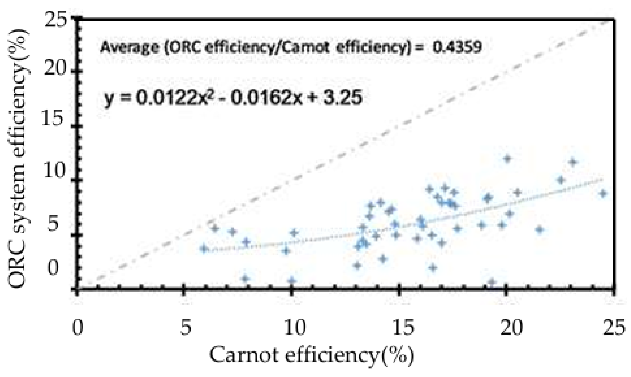
Organic Rankine cycle (ORC) is a kind of Rankine cycle characterized by using organic fluid as the work media ORC can be applied to harvest waste energy from low-temperature heat resource like solar energy, geothermal energy, waste heat in ICE coolant circuit and exhaust gas and PEMFC [90,91,92] Most of the ORC related research being championed are modelling based and does not really present a real-life scenario of the fuel cell system investigated in transport sector [27]. ORC is an important technology for the low-grade heat recovery from PEMFC due to its relatively high thermal efficiency. Park et al. [93] summarizes the current state-of-the-art experimental ORC system performance based on 200 scientific works according to specific selection criteria covering waste temperature range of .As shown in Figure 13, in general, the overall heat to electrical power conversion efficiency was around 44% of the Carnot cycle efficiency of the cycle. Taking the working temperature of 80 °C, environment temperature of 20 °C, Carnot cycle efficiency defining the ceiling of ORC which is around 17%, the average thermal efficiency of ORC is about 7.4%.
Representative research results on waste heat recovery with ORC is summaried in Table 1 where ORC is combined with other waste heat solutions, e.g. regenerator [94], recuperator and Metal Hybrid for Hydrogen storage [95], which brings around 5% efficiency increasement In 2016, He et al. [96] reported a thermal efficiency of 4.73% is achieved with a heat pump combined with ORC for WHR from the fuel cell of 49.8kW. The ORC efficiency listed in Table 1 shows a comparable average value to that in Figure 13, and the low working temperature interval of ORC may be a possible reason. Therefore, the optimization of ORC scenario is important to further enhance the thermal efficiency of ORC and overall efficiency of PEMFC systems, such as combining regenerator [94] or recuperator [95].On the meantime experiment result carried by vehicle manufacture such as PSA,Hino on engine coolant waste heat recovery shows a promosing value for vehicle application [92,97]
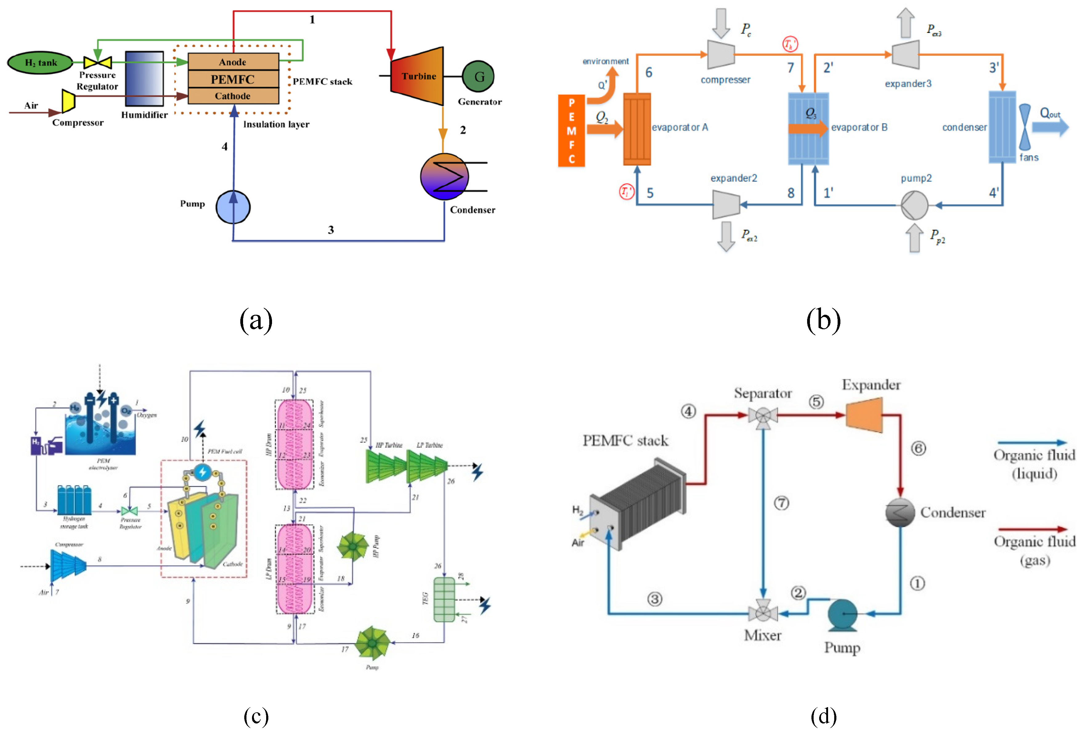
Zhao et al. [98] put forward a hybrid power system that utilizes ORC to recover waste heat from PEMFC, as depicted in Figure 14(a). The findings demonstrate that the total electric efficiency of the hybrid power system can be increased by approximately 5% with the assistance of the ORC-based waste heat recovery system. This study also emphasized the effects of fuel flow rate, operating pressure, turbine inlet pressure, and backpressure on the efficiency of the thermodynamic process.He et al. [96] compared the performance of two ORC-based systems for recovering waste heat from PEMFC. One is a standalone ORC system, while the other is an ORC and heat pump combined system, as shown in Figure 14(b). The results reported a thermal efficiency of 4.73% for the ORC and heat pump combined system, and it was proved that the ORC and heat pump combined system is more feasible for the cooling of PEMFC. Azad et al. [99] analyzed the performance of two-stage ORC (STORC) and PEMFC integrated system as shown in Figure 14(c), the results indicate that operate a STORC with wasted heat from the PEMFC could improve overall efficiency by 1.9%. Liu et al. [100] proposed a new thermal management concept in which the organic material is applied both for phase change cooling and waste heat recovery, the system layout is shown in Figure 14(d). By using a specially designed cooling plate in the cooling circuit to generate a higher vapor content in the working fluid, more power is provided to drive the turbine, resulting in an ORC thermal efficiency of 7%.

Table 1.
Typical waste heat recovery by ORC in PEMFCs.
| Overheating /Recuperator | Waste heat source | Resear-ch type | Organic fluid | ORC Eff. | Overall Eff. | Improved efficiency (absolute value) | Ref. |
| / | 1007kW Fuel cell |
simu-lation | R123 R245ca R245fa |
10.94% 10.70% 10.59% |
/ | 5.24% 5.13% 5.08% |
[98] |
| With transcritical CO2cycle and cold energy of liquefied natural gas | 1047 kW electric power output with 1190 kW heat | simu-lation | / | / | 72% | 33% | [101] |
| ORC | 49.8 kW fuel cell | simu-lation | R245fa | 4.03% | / | / | [96] |
| Heat pump and ORC | 49.8 kW fuel cell | Water for HP R123 for ORC |
4.73% | / | / | ||
| Recuperator +Metal Hybrid for Hydrogen storage | 1180kW fuel cell | simu-lation | R123 | 6.52% | 44.3% | 2.3% | [95] |
In the combined system, there are numerous heat transfer processes occurring between the heat source and the working fluids, The exergy destroyed in the heat exchangers (evaporator and condenser) amounts to 74% of the overall exergy loss while the share of evaporator is higher Below parameters must be comprehensively considered: pinch point temperature difference (PPTD) of the evaporator and condenser, heat exchanger effectiveness, pump and turbine efficiency, installation, environment protection and running costs [102,103].
4.2.2. Other Thermodynamic Cycles
Except for ORC, other thermodynamic cycles also show the potential to recover waste heat from PEMFC and enhance the overall system efficiency, such as CO2 cycle and Kalina cycle. Ahmadi et al. [101] proposed a hybrid WHR system consists of a trans-critical carbon dioxide cycle and a liquefied natural gas to reduce the condensing temperature in a PEMFC. With the proposed system, generated power of the system increases by 39%. Kalina cycle can be used in low temperature applications for cogeneration with different power cycles to recovery waste heat from gas turbine, diesel engine, geothermal heat and solar energy as well [104]. It uses a zeotropic mixture of water and ammonia as working fluid to maximize the power output from turbine and reduce the power input in the pumps [105] .Due to the advantage of heat utilization with ammonia-water mixture, Kalina cycle usually shows higher efficiency than ORC with the same boundary condition [106]. Kalina cycle offers many advantages compared to ORC including superior performance, higher flexibility, and reduced heat transfer temperature difference between its working fluid and heat source, Kalina cycle are recommended for further investigation for waste heat recovery in FCEV. Taking liquid nature gas (LNG) as heat sink , Wang et al. [107] improved the turbine output power by lowering the turbine back pressure. However, the working pressure level is higher in Kalina cycle than that in ORC cycle which calls for high level engineering integration and the risk of two phase working fluid for ORC at expander’s outlet is lower for ORC cycle [108].
Wang et al. [109] proposed to calssify the waste heat source into convext type, stratight type and concave type according to heat profile’s Temperature-Enthalpy (T-H) diagram. For convex type waste heat source, the thermal match between organic working fluid’s evaporation curve and heat source is best, so ORC is the best selection, while for the straight and concave type of waste heat, Kalina cycle is more suitable. The work can provide a reference to choose a suitable technology to recover low temperature waste heat for power generation in the process industry.
4.2.3. Combined Heat/Cooling and Power Based on PEMFC
Uilization of waste heat for cabin heating [110], preheating of reactants [111] , heating to facilitate water evaporation [112] and hydrogen release from metal hydrides tank [113] already demonstrate their advancements in the overall system’s power-saving capabilities. PEMFC can also work as the main power in a distributed combined heat/cooling and power (CHP/CCP) systems, which can provide electricity and reuse waste heat during electricity production with high energy efficiency. As shown in Figure 14, , PEMFC based combined heat and power (PEMFC-CHP) system is an efficient way to provide electricity and heat to specific users, achieving a sustainable reduction in carbon emissions [114]. The influence of CCP, CHP systems on the enhancement of overall efficiency, particularly in low environmental temperature operations, is evident and can provide direct guidance for the design of Organic Rankine Cycle (ORC) systems [63].
Figure 14.
Scheme of PEMFC-CHP system with liquid cooling [114].
Figure 14.
Scheme of PEMFC-CHP system with liquid cooling [114].
4.2.4. Thermoelectric Generators
Thermoelectric generators is an important low-grade heat recovery technology due to its simple structure, no moving parts, environment friendliness, extremely low noise [115]. For application, as early as 2009, BMW studied exhaust waste heat recovery in an ICE power BMW 530I, the conversion efficiency of TEGs measured is around 1~2.5% for typical driving cycles showing a distinct relying on waste heat source [116,117] . A fuel consumption of 3% reduction is reported from Honda team through simulation and test in a series hybrid vehicle [118]. A TEG operates at approximately 20% of the Carnot efficiency over a wide temperature range as summarized by [119]. Orr et al. [120] proposed to apply TEG and heat pump in combination to enhance the heat recovery efficiency and create a completely solid state and passive WHR system. On the contrary, Hasani et al. [121] concluded that using thermoelectric coolers can be a suitable solution for recovering waste heat from a PEM fuel cell. In their experiment, a heater is applied to simulate the waste heat produced as that from a 5 kW PEMFC, a specially designed waste heat recovery system can recovery about 10% of waste heat transferred through cooling and the thermoelectric conversion efficiency is 0.35%.
4.2.5. Metal Hydrides
Nasri et al. [113] introduced method of WHR for FCEVs with thermochemical energy storage-metal hydrides. Using metal hydrides to store the waste heat of the powertrain components during normal operation and to release it for the start-up at very low ambient temperatures, the simulated range increase from 152 km to 178 km at -20°C ambient temperature. A main barrier to the practical use of metal hydrides is the prohibitively high temperatures and pressures necessary for reversible operation [50,116]. Most metal hydrides cannot store much hydrogen, and such hydrides have slow kinetics and do not release hydrogen at low temperature [122]. This kind of waste heat recovery is not recommend for combination with liquid cooling [50].
Different with cooling system definition in PEMFCs, there is not a clear technical path for waste heat recoery form FECVs though. Even though, combined heat and power, combined chilling and power proved a possible soluton for vehicle application within narrow temperature range with one choice. Thermodynamic cycles can recovery waste heat recovery showing better environment compactbility though entensive research on matching and feasiblity study is urgently needed. Due to the enthusiasm shown by the automotive industry and academia in the field of waste heat utilization, especially in the utilization of individual cooling water waste heat, it is optimistic that with the increasing demand for system efficiency and the reduction of parasitic power in thermal management systems, research and development in waste heat utilization will be reignited. It’s reasonable to expect more integrated cooling system and waste heat recovery from bottom level hardware and configuration design [123].
5. Conclusions
The original motivation of this review is to summarize the lasted achievements in thermal management of PEMFC for improvement of thermal efficiency, specially focusing on working mechanism and engineering application from the perspective of system integration and optimization. The first itemis efficient cooling methods to maintain the PEMFC under proper working temperature range, which means the pursuit of efficiency enhancement through the optimization of working temperatures, solutions aimed at temperature uniformity, and strategies for minimizing parasitic power consumption of cooling system. The other one is waste heat recovery from PEMFC and improve the overall system efficiency, including organic Rankine cycle, Kalina cycle and thermoelectric generators etc. Focusing specifically on the fuel cell stack, we anticipate an increment of approximately 5% in system efficiency through integrated thermal management system including efficient cooling and waste heat recovery, and this goal can be achieved with aid of optimum operation temperature and control, parasitic power reduction and waste heat recovery.The main conclusions and findings are drawn as follows:
(1) Optimum operation temperature and control: Achieving a 2-3% increase in efficiency by maintaining the fuel cell stack at its optimal operating temperature. This is crucial for ensuring stable operation and maximizing performance, with as the efficiency of the stack is greatly influenced by its temperature.
(2) Parasitic power reduction: A further 1-2% efficiency gain can be realized by minimizing the parasitic power loss associated with auxiliary systems such as fans and water pumps and actuator valves.
(3) Waste heat recovery: An additional 2-3% improvement in efficiency is feasible through the integration of an Organic Rankine Cycle (ORC) system for waste heat recovery. It is worth noting that the efficiency of the ORC system is bound by the Carnot cycle, its efficiency will further increase under cold conditions when the condenser working temperature gets lower.
(4) The provided information shall be valuable to guide the system layout and control strategies for ITMS with ORC at the early design stage. A systematic research on integration of cooling system and waste heat recovery system shall be a focus to study the overal PEMFC system behavior and parasitic power reduciton in fucture. Besides, the integration of AI and enhanced computing capabilities is progressively enabling the engineering realization of comprehensive models, multi objective optimization and precise control systems that were previously unattainable.
Author Contributions
Conceptualization, Q.W. and J.C.; methodology, Q.W.; formal analysis, Q.W.; investigation, Q.W. and ZL.D.; resources, XF.Z.; writing—original draft preparation, Q.W.; writing—review and editing, A.I. and J.C.; visualization, Q.W.; supervision, XF.Z.; project administration, CK.Z.; funding acquisition, XF.Z. All authors have read and agreed to the published version of the manuscript.
Funding
The present study is greatly supported by Gongtai Electronic Co., Ltd (Grand No. 204000-H12420), Zhejiang Provincial Emergency Department Project (Grant No. 2024YJ023) and Key R&D Program of the Ministry of Science and Technology of China (Grant No. 2023YFB3209805).
Conflicts of Interest
The authors declare no conflict of interest.
References
- Wee, J.-H. Applications of proton exchange membrane fuel cell systems. Renewable and Sustainable Energy Reviews 2007, 11, 1720-1738. [CrossRef]
- Wang, D.; Ling, X.; Peng, H.; Liu, L.; Tao, L. Efficiency and optimal performance evaluation of organic Rankine cycle for low grade waste heat power generation. Energy 2013, 50, 343-352. [CrossRef]
- Zhou, F.; Joshi, S.N.; Rhote-Vaney, R.; Dede, E.M. A review and future application of Rankine Cycle to passenger vehicles for waste heat recovery. Renewable and Sustainable Energy Reviews 2017, 75, 1008-1021. [CrossRef]
- Jiao, K.; Xuan, J.; Du, Q.; Bao, Z.; Xie, B.; Wang, B.; Zhao, Y.; Fan, L.; Wang, H.; Hou, Z.; et al. Designing the next generation of proton-exchange membrane fuel cells. Nature 2021, 595, 361-369. [CrossRef]
- Li, Y.; Taghizadeh-Hesary, F. The economic feasibility of green hydrogen and fuel cell electric vehicles for road transport in China. Energy Policy 2022, 160. [CrossRef]
- Fan, L.; Tu, Z.; Chan, S.H. Recent development of hydrogen and fuel cell technologies: A review. Energy Reports 2021, 7, 8421-8446. [CrossRef]
- Lohse-Busch, H.; Stutenberg, K.; Duoba, M.; Liu, X.; Elgowainy, A.; Wang, M.; Wallner, T.; Richard, B.; Christenson, M. Automotive fuel cell stack and system efficiency and fuel consumption based on vehicle testing on a chassis dynamometer at minus 18 °C to positive 35 °C temperatures. International Journal of Hydrogen Energy 2020, 45, 861-872. [CrossRef]
- Matsunaga, M.; Fukushima, T.; Ojima, K. Powertrain System of Honda FCX Clarity Fuel Cell Vehicle. World Electric Vehicle Journal 2009, 3, 820-829. [CrossRef]
- Cullen, D.A.; Neyerlin, K.C.; Ahluwalia, R.K.; Mukundan, R.; More, K.L.; Borup, R.L.; Weber, A.Z.; Myers, D.J.; Kusoglu, A. New roads and challenges for fuel cells in heavy-duty transportation. Nature Energy 2021, 6, 462-474. [CrossRef]
- Khanna, N.; Lu, H.; Fridley, D.; Zhou, N. Near and long-term perspectives on strategies to decarbonize China’s heavy-duty trucks through 2050. Scientific Reports 2021, 11, 20414. [CrossRef]
- Figueroa-Santos, M.A.; Stefanopoulou, A.G. Fuel Cell Vehicle Optimization and Control. In Encyclopedia of Systems and Control, Baillieul, J., Samad, T., Eds.; Springer London: London, 2020; pp. 1-9.
- Wang, Y.; Ruiz Diaz, D.F.; Chen, K.S.; Wang, Z.; Adroher, X.C. Materials, technological status, and fundamentals of PEM fuel cells – A review. Materials Today 2020, 32, 178-203. [CrossRef]
- Zhang, X.; Li, H.; Yang, J.; Lei, Y.; Wang, C.; Wang, J.; Tang, Y.; Mao, Z. Recent advances in Pt-based electrocatalysts for PEMFCs. RSC Advances 2021, 11, 13316-13328. [CrossRef]
- Wang, K.; Zhou, T.; Cao, Z.; Yuan, Z.; He, H.; Fan, M.; Jiang, Z. Advanced 3D ordered electrodes for PEMFC applications: From structural features and fabrication methods to the controllable design of catalyst layers. Green Energy & Environment 2023. [CrossRef]
- Gerling, C.; Hanauer, M.; Berner, U.; Friedrich, K.A.K. PEMFC Model Parameterization By Means of Differential Cell Polarization and Electrochemical Impedance Spectroscopy. ECS Meeting Abstracts 2020, MA2020-02, 3844. [CrossRef]
- Wang, J.; He, H.; Wu, Y.; Yang, C.; Zhang, H.; Zhang, Q.; Li, J.; Cheng, H.; Cai, W. Review on Electric Resistance in Proton Exchange Membrane Fuel Cells: Advances and Outlook. Energy & Fuels 2024, 38, 2759-2776. [CrossRef]
- Tanaka, S.; Bradfield, W.W.; Legrand, C.; Malan, A.G. Numerical and experimental study of the effects of the electrical resistance and diffusivity under clamping pressure on the performance of a metallic gas-diffusion layer in polymer electrolyte fuel cells. Journal of Power Sources 2016, 330, 273-284. [CrossRef]
- Liu, Q.; Lan, F.; Chen, J.; Zeng, C.; Wang, J. A review of proton exchange membrane fuel cell water management: Membrane electrode assembly. Journal of Power Sources 2022, 517. [CrossRef]
- Kumar, R.; Subramanian, K.A. Enhancement of efficiency and power output of hydrogen fuelled proton exchange membrane (PEM) fuel cell using oxygen enriched air. International Journal of Hydrogen Energy 2023, 48, 6067-6075. [CrossRef]
- Zhang, J.; Wang, C.; Zhang, A. Experimental study on temperature and performance of an open-cathode PEMFC stack under thermal radiation environment. Applied Energy 2022, 311. [CrossRef]
- Zhang, Y.; Xu, S.; Lin, C. Performance improvement of fuel cell systems based on turbine design and supercharging system matching. Applied Thermal Engineering 2020. [CrossRef]
- Wu, B.; Matian, M.; Offer, G.J. Hydrogen PEMFC system for automotive applications. International Journal of Low-Carbon Technologies 2012, 7, 28-37. [CrossRef]
- Baz, F.B.; Elzohary, R.M.; Osman, S.; Marzouk, S.A.; Ahmed, M. A review of water management methods in proton exchange membrane fuel cells. Energy Conversion and Management 2024, 302. [CrossRef]
- Kwan, T.H.; Katsushi, F.; Shen, Y.; Yin, S.; Zhang, Y.; Kase, K.; Yao, Q. Comprehensive review of integrating fuel cells to other energy systems for enhanced performance and enabling polygeneration. Renewable and Sustainable Energy Reviews 2020, 128. [CrossRef]
- Jiang, H.; Xu, L.; Li, J.; Hu, Z.; Ouyang, M. Energy management and component sizing for a fuel cell/battery/supercapacitor hybrid powertrain based on two-dimensional optimization algorithms. Energy 2019, 177, 386-396. [CrossRef]
- Yoshizumi, T.; Kubo, H.; Okumura, M. Development of High-Performance FC Stack for the New MIRAI. In Proceedings of the SAE Technical Paper Series, 2021.
- Wilberforce, T.; Olabi, A.G.; Muhammad, I.; Alaswad, A.; Sayed, E.T.; Abo-Khalil, A.G.; Maghrabie, H.M.; Elsaid, K.; Abdelkareem, M.A. Recovery of waste heat from proton exchange membrane fuel cells – A review. International Journal of Hydrogen Energy 2022. [CrossRef]
- Javaid, U.; Mehmood, A.; Arshad, A.; Imtiaz, F.; Iqbal, J. Operational Efficiency Improvement of PEM Fuel Cell—A Sliding Mode Based Modern Control Approach. IEEE Access 2020, 8, 95823-95831. [CrossRef]
- Xiaoyu Guo, Z.D., Jiabin Shen, Yiqiao Xu, Qiaohui He, Xiaowei Zhao, Zhengtao Ding. Towards intelligent and integrated architecture for hydrogen fuel cell system challenges and approaches. National Science Open 2023. [CrossRef]
- Wu, D.; Peng, C.; Yin, C.; Tang, H. Review of System Integration and Control of Proton Exchange Membrane Fuel Cells. Electrochemical Energy Reviews 2020, 3, 466-505. [CrossRef]
- Fan, L.; Tu, Z.; Chan, S.H. Recent development in design a state-of-art proton exchange membrane fuel cell from stack to system: Theory, integration and prospective. International Journal of Hydrogen Energy 2023, 48, 7828-7865. [CrossRef]
- Islam, M.R.; Shabani, B.; Rosengarten, G.; Andrews, J. The potential of using nanofluids in PEM fuel cell cooling systems: A review. Renewable and Sustainable Energy Reviews 2015, 48, 523-539. [CrossRef]
- Xing, L.; Xiang, W.; Zhu, R.; Tu, Z. Modeling and thermal management of proton exchange membrane fuel cell for fuel cell/battery hybrid automotive vehicle. International Journal of Hydrogen Energy 2022, 47, 1888-1900. [CrossRef]
- Yu, X.; Zhou, B.; Sobiesiak, A. Water and thermal management for Ballard PEM fuel cell stack. Journal of Power Sources 2005, 147, 184-195. [CrossRef]
- Javaid, U.; Iqbal, J.; Mehmood, A.; Uppal, A.A. Performance improvement in polymer electrolytic membrane fuel cell based on nonlinear control strategies-A comprehensive study. PLoS One 2022, 17, e0264205. [CrossRef]
- Wang, Q.; Li, B.; Yang, D.; Dai, H.; Zheng, J.P.; Ming, P.; Zhang, C. Research progress of heat transfer inside proton exchange membrane fuel cells. Journal of Power Sources 2021, 492. [CrossRef]
- Amphlett, J.C.; Baumert, R.M.; Mann, R.F.; Peppley, B.A.; Roberge, P.R.; Harris, T.J. Performance Modeling of the Ballard Mark IV Solid Polymer Electrolyte Fuel Cell: II . Empirical Model Development. Journal of The Electrochemical Society 1995, 142, 9. [CrossRef]
- Benmouiza, K.; Cheknane, A. Analysis of proton exchange membrane fuel cells voltage drops for different operating parameters. International Journal of Hydrogen Energy 2018, 43, 3512-3519. [CrossRef]
- Zhang, G.; Wu, J.; Wang, Y.; Yin, Y.; Jiao, K. Investigation of current density spatial distribution in PEM fuel cells using a comprehensively validated multi-phase non-isothermal model. International Journal of Heat and Mass Transfer 2020, 150. [CrossRef]
- O'Hayre, R.; Cha, S.-W.; Colella, W.; Prinz, F.B. Chapter 3: Fuel Cell Reaction Kinetics. In Fuel Cell Fundamentals; New York: John Wiley & Sons: 2016; pp. 77-116.
- Wei Jiuxuan, Q.M.; Zhang Hong; Xue, L. Investigation on exhaust energy recovery system using radial turbine in high-power proton exchange membrane fuel cells. In Proceedings of the Proceedings of ASME Turbo Expo 2022,Turbomachinery Technical Conference and Exposition, Rotterdam, 2022.
- Xu, B.; Li, D.; Ma, Z.; Zheng, M.; Li, Y. Thermodynamic Optimization of a High Temperature Proton Exchange Membrane Fuel Cell for Fuel Cell Vehicle Applications. Mathematics 2021, 9, 1792. [CrossRef]
- Abd El Monem, A.A.; Azmy, A.M.; Mahmoud, S.A. Effect of process parameters on the dynamic behavior of polymer electrolyte membrane fuel cells for electric vehicle applications. Ain Shams Engineering Journal 2014, 5, 75-84. [CrossRef]
- Zhang, G.; Qu, Z.; Tao, W.-Q.; Mu, Y.; Jiao, K.; Xu, H.; Wang, Y. Advancing next-generation proton-exchange membrane fuel cell development in multi-physics transfer. Joule 2024, 8, 45-63. [CrossRef]
- Yan, Q.; Toghiani, H.; Causey, H. Steady state and dynamic performance of proton exchange membrane fuel cells (PEMFCs) under various operating conditions and load changes. Journal of Power Sources 2006, 161, 492-502. [CrossRef]
- Kurnia, J.C.; Sasmito, A.P. Hydrogen Fuel Cell in Vehicle Propulsion: Performance, Efficiency, and Challenge. In Energy Efficiency in Mobility Systems; 2020; pp. 9-26.
- Zhang, G.; Kandlikar, S.G. A critical review of cooling techniques in proton exchange membrane fuel cell stacks. International Journal of Hydrogen Energy 2012, 37, 2412-2429. [CrossRef]
- Fly, A.; Thring, R.H. A comparison of evaporative and liquid cooling methods for fuel cell vehicles. International Journal of Hydrogen Energy 2016, 41, 14217-14229. [CrossRef]
- Garrity, P.T.; Klausner, J.F.; Mei, R. A Flow Boiling Microchannel Evaporator Plate for Fuel Cell Thermal Management. Heat Transfer Engineering 2007, 28, 877-884. [CrossRef]
- Nguyen, H.Q.; Shabani, B. Proton exchange membrane fuel cells heat recovery opportunities for combined heating/cooling and power applications. Energy Conversion and Management 2020, 204. [CrossRef]
- Hwang, S.H.; Kim, M.S. An experimental study on the cathode humidification and evaporative cooling of polymer electrolyte membrane fuel cells using direct water injection method at high current densities. Applied Thermal Engineering 2016, 99, 635-644. [CrossRef]
- Xu, J.; Zhang, C.; Wan, Z.; Chen, X.; Chan, S.H.; Tu, Z. Progress and perspectives of integrated thermal management systems in PEM fuel cell vehicles: A review. Renewable and Sustainable Energy Reviews 2022, 155. [CrossRef]
- Luo, M.; Zhang, J.; Zhang, C.; Chin, C.S.; Ran, H.; Fan, M.; Du, K.; Shuai, Q. Cold start investigation of fuel cell vehicles with coolant preheating strategy. Applied Thermal Engineering 2022, 201, 117816. [CrossRef]
- SAKAJO,, Y.; YAMAMOTO,, T.; OKAJIMA,, M.; KONDO,, Y.; OIDE, H. Thermal Management System for Fuel Cell Vehicles. DENSO TECHNICAL REVIEW 2019, 24, https://www.denso.com/jp/ja/-/media/global/ business/ innovation/ review/24/24-doc-16-paper-11.pdf.
- Yan, X.; Peng, Y.; Shen, Y.; Shen, S.; Wei, G.; Yin, J.; Zhang, J. The use of phase-change cooling strategy in proton exchange membrane fuel cells: A numerical study. Science China Technological Sciences 2021, 64, 2762-2770. [CrossRef]
- Choi, E.J.; Park, J.Y.; Kim, M.S. A comparison of temperature distribution in PEMFC with single-phase water cooling and two-phase HFE-7100 cooling methods by numerical study. International Journal of Hydrogen Energy 2018, 43, 13406-13419. [CrossRef]
- Luo, L.; Huang, B.; Xingying, B.; Cheng, Z.; Qifei, J. Temperature uniformity improvement of a proton exchange membrane fuel cell stack with ultra-thin vapor chambers. Applied Energy 2020, 270, 115192. [CrossRef]
- Li, Q.; Wang, C.; Wang, C.; Zhou, T.; Zhang, X.; Zhang, Y.; Zhuge, W.; Sun, L. Comparison of organic coolants for boiling cooling of proton exchange membrane fuel cell. Energy 2023, 266. [CrossRef]
- Choi, E.J.; Park, J.Y.; Kim, M.S. Two-phase cooling using HFE-7100 for polymer electrolyte membrane fuel cell application. Applied Thermal Engineering 2019, 148, 868-877. [CrossRef]
- Guo, J.; Li, Z.; Wei, L.; Fangming, J. A novel thermal management system with a heat-peak regulator for fuel cell vehicles. Journal of Cleaner Production 2023, 414. [CrossRef]
- Chen, X.; Zhou, F.; Yang, W.; Gui, Y.; Zhang, Y. A hybrid thermal management system with liquid cooling and composite phase change materials containing various expanded graphite contents for cylindrical lithium-ion batteries. Applied Thermal Engineering 2022, 200. [CrossRef]
- James, B.D. Fuel Cell Cost and Performance Analysis. Available online: https://www.hydrogen.energy.gov/docs /hydrogenprogramlibraries/pdfs/review22/fc353_james_2022_o-pdf.pdf?Status=Master (accessed on 18th,Dec.,2024).
- Fan, L.; Liu, Y.; Luo, X.; Tu, Z.; Chan, S.H. Comparison and evaluation of mega watts proton exchange membrane fuel cell combined heat and power system under different waste heat recovery methods. Renewable Energy 2023, 210, 295-305. [CrossRef]
- Han, J.; Yu, S. Ram air compensation analysis of fuel cell vehicle cooling system under driving modes. Applied Thermal Engineering 2018, 142, 530-542. [CrossRef]
- Yu, Y.; Chen, M.; Zaman, S.; Xing, S.; Wang, M.; Wang, H.J. Thermal management system for liquid-cooling PEMFC stack: From primary configuration to system control strategy. Etransportation 2022, 12, doi:ARTN 10016510.1016/j.etran.2022.100165.
- Liu, Z.; Chen, J.; Kumar, L.; Jin, L.; Huang, L. Model-based decoupling control for the thermal management system of proton exchange membrane fuel cells. International Journal of Hydrogen Energy 2023, 48, 19196-19206. [CrossRef]
- Chen, Q.; Zhang, G.; Zhang, X.; Sun, C.; Jiao, K.; Wang, Y. Thermal management of polymer electrolyte membrane fuel cells: A review of cooling methods, material properties, and durability. Applied Energy 2021, 286, 116496. [CrossRef]
- Rojas, J.D.; Kunusch, C.; Ocampo-Martinez, C.; Puig, V. Control-Oriented Thermal Modeling Methodology for Water-Cooled PEM Fuel-Cell-Based Systems. IEEE Transactions on Industrial Electronics 2015, 62, 5146-5154. [CrossRef]
- Zhiani, M.; Majidi, S.; Silva, V.B.; Gharibi, H. Comparison of the performance and EIS (electrochemical impedance spectroscopy) response of an activated PEMFC (proton exchange membrane fuel cell) under low and high thermal and pressure stresses. Energy 2016, 97, 560-567. [CrossRef]
- Baroutaji, A.; Arjunan, A.; Ramadan, M.; Robinson, J.; Alaswad, A.; Abdelkareem, M.A.; Olabi, A.-G. Advancements and prospects of thermal management and waste heat recovery of PEMFC. International Journal of Thermofluids 2021, 9. [CrossRef]
- Desantes, J.M.; Novella, R.; Lopez-Juarez, M.; Nidaguila, I. Experimental assessment of a heavy-duty fuel cell system in relevant operating conditions. Applied Energy 2024, 376. [CrossRef]
- Sun, Z.; Chen, Z.; Wang, Y.; Yuan, H. PEM Fuel Cell Thermal Management Strategy Based on Multi-model Predictive Control. In Proceedings of the 2022 IEEE/IAS Industrial and Commercial Power System Asia (I&CPS Asia), 2022; pp. 625-630.
- Hu, D.; Wang, Y.; Li, J.; Yang, Q.; Wang, J. Investigation of optimal operating temperature for the PEMFC and its tracking control for energy saving in vehicle applications. Energy Conversion and Management 2021, 249. [CrossRef]
- Tang, X.; Zhang, Y.; Xu, S. Experimental study of PEM fuel cell temperature characteristic and corresponding automated optimal temperature calibration model. Energy 2023, 283. [CrossRef]
- Qu, S.; Li, X.; Hou, M.; Shao, Z.; Yi, B. The effect of air stoichiometry change on the dynamic behavior of a proton exchange membrane fuel cell. Journal of Power Sources 2008, 185, 302-310. [CrossRef]
- Zhang, G.; Yuan, H.; Wang, Y.; Jiao, K. Three-dimensional simulation of a new cooling strategy for proton exchange membrane fuel cell stack using a non-isothermal multiphase model. Applied Energy 2019, 255. [CrossRef]
- Weng, X.; Huang, R.; Yu, X.; Chen, J.; Yang, A. Design and application of a thermal characteristic test platform for hydrogen fuel cells. SCIENTIA SINICA Technologica 2023, 53, 363-374. [CrossRef]
- Cheng, S.; Fang, C.; Xu, L.; Li, J.; Ouyang, M. Model-based temperature regulation of a PEM fuel cell system on a city bus. International Journal of Hydrogen Energy 2015, 40, 13566-13575. [CrossRef]
- Tian, P.; Liu, X.; Luo, K.; Li, H.; Wang, Y. Deep learning from three-dimensional multiphysics simulation in operational optimization and control of polymer electrolyte membrane fuel cell for maximum power. Applied Energy 2021, 288, 116632. [CrossRef]
- Marcinkoski, J.; Ram Vijayagopal; Jesse Adams; Brian James; John Kopasz; Ahluwalia, R. Hydrogen Class 8 Long Haul Truck Targets. Available online: https://www.hydrogen.energy.gov/docs/hydrogenprogramlibraries/pdfs/19006 _hydrogen_class8long_haul_truck_targets.pdf?Status=Master (accessed on 18th.Dec.,2024).
- Ahn, J.-W.; Choe, S.-Y. Coolant controls of a PEM fuel cell system. Journal of Power Sources 2008, 179, 252-264. [CrossRef]
- Chang, G.; Xie, C.; Cui, X.; Wei, P. Research on Parasitic Power of Cooling Balance of Plant System for Proton Exchange Membrane Fuel Cell. Journal of Thermal Science and Engineering Applications 2023, 15. [CrossRef]
- Han, J.; Park, J.; Yu, S. Control strategy of cooling system for the optimization of parasitic power of automotive fuel cell system. International Journal of Hydrogen Energy 2015, 40, 13549-13557. [CrossRef]
- Zheng, C.H.; Kim, N.W.; Park, Y.I.; Lim, W.S.; Cha, S.W.; Xu, G.Q. The effect of battery temperature on total fuel consumption of fuel cell hybrid vehicles. International Journal of Hydrogen Energy 2013, 38, 5192-5200. [CrossRef]
- Song, Z.; Pan, Y.; Chen, H.; Zhang, T. Effects of temperature on the performance of fuel cell hybrid electric vehicles: A review. Applied Energy 2021, 302. [CrossRef]
- Li, Q.; Liu, Z.; Sun, Y.; Yang, S.; Deng, C. A Review on Temperature Control of Proton Exchange Membrane Fuel Cells. Processes 2021, 9. [CrossRef]
- Kandidayeni, M.; Macias, A.; Boulon, L.; Kelouwani, S. Investigating the impact of ageing and thermal management of a fuel cell system on energy management strategies. Applied Energy 2020, 274. [CrossRef]
- Bao, C.; Ouyang, M.; Yi, B. Modeling and optimization of the air system in polymer exchange membrane fuel cell systems. Journal of Power Sources 2006, 156, 232-243. [CrossRef]
- Chen, F.; Pei, Y.; Jiao, J.; Chi, X.; Hou, Z. Energy flow and thermal voltage analysis of water-cooled PEMFC stack under normal operating conditions. Energy 2023, 275. [CrossRef]
- Li, J.; Y, Z.; D., Y. Organic Rankine cycles using zeotropic mixtures driven by low-to-medium temperature thermal energy. Journal of Tsinghua University (Science and Technology) 2022, 62, 11.
- Tchanche, B.F.; Papadakis, G.; Lambrinos, G.; Frangoudakis, A. Fluid selection for a low-temperature solar organic Rankine cycle. Applied Thermal Engineering 2009, 29, 2468-2476. [CrossRef]
- Mansour, C.; Bou Nader, W.; Dumand, C.; Nemer, M. Waste heat recovery from engine coolant on mild hybrid vehicle using organic Rankine cycle. Proceedings of the Institution of Mechanical Engineers, Part D: Journal of Automobile Engineering 2018, 233, 2502-2517. [CrossRef]
- Park, B.-S.; Usman, M.; Imran, M.; Pesyridis, A. Review of Organic Rankine Cycle experimental data trends. Energy Conversion and Management 2018, 173, 679-691. [CrossRef]
- Peris, B.; Navarro-Esbrí, J.; Molés, F. Bottoming organic Rankine cycle configurations to increase Internal Combustion Engines power output from cooling water waste heat recovery. Applied Thermal Engineering 2013, 61, 364-371. [CrossRef]
- Alijanpour sheshpoli, M.; Mousavi Ajarostaghi, S.S.; Delavar, M.A. Waste heat recovery from a 1180 kW proton exchange membrane fuel cell (PEMFC) system by Recuperative organic Rankine cycle (RORC). Energy 2018, 157, 353-366. [CrossRef]
- He, T.; Shi, R.; Peng, J.; Zhuge, W.; Zhang, Y. Waste Heat Recovery of a PEMFC System by Using Organic Rankine Cycle. Energies 2016, 9. [CrossRef]
- Furukawa, T.; Nakamura, M.; Machida, K.; Shimokawa, K. A Study of the Rankine Cycle Generating System for Heavy Duty HV Trucks. In Proceedings of the SAE Technical Paper Series, 2014.
- Zhao, P.; Wang, J.; Gao, L.; Dai, Y. Parametric analysis of a hybrid power system using organic Rankine cycle to recover waste heat from proton exchange membrane fuel cell. International Journal of Hydrogen Energy 2012, 37, 3382-3391. [CrossRef]
- Azad, A.; Fakhari, I.; Ahmadi, P.; Javani, N. Analysis and optimization of a fuel cell integrated with series two-stage organic Rankine cycle with zeotropic mixtures. International Journal of Hydrogen Energy 2022, 47, 3449-3472. [CrossRef]
- Liu, G.; Qin, Y.; Ji, D. Numerical investigation of organic fluid flow boiling for proton exchange membrane fuel cell cooling and waste heat recovery. Applied Thermal Engineering 2023, 228. [CrossRef]
- Ahmadi, M.H.; Mohammadi, A.; Pourfayaz, F.; Mehrpooya, M.; Bidi, M.; Valero, A.; Uson, S. Thermodynamic analysis and optimization of a waste heat recovery system for proton exchange membrane fuel cell using transcritical carbon dioxide cycle and cold energy of liquefied natural gas. Journal of Natural Gas Science and Engineering 2016, 34, 428-438. [CrossRef]
- Bademlioglu, A.H.; Canbolat, A.S.; Yamankaradeniz, N.; Kaynakli, O. Investigation of parameters affecting Organic Rankine Cycle efficiency by using Taguchi and ANOVA methods. Applied Thermal Engineering 2018, 145, 221-228. [CrossRef]
- Li, J.; Pei, G.; Li, Y.; Wang, D.; Ji, J. Energetic and exergetic investigation of an organic Rankine cycle at different heat source temperatures. Energy 2012, 38, 85-95. [CrossRef]
- Omar, A.; Saghafifar, M.; Mohammadi, K.; Alashkar, A.; Gadalla, M. A review of unconventional bottoming cycles for waste heat recovery: Part II – Applications. Energy Conversion and Management 2019, 180, 559-583. [CrossRef]
- Saghafifar, M.; Omar, A.; Mohammadi, K.; Alashkar, A.; Gadalla, M. A review of unconventional bottoming cycles for waste heat recovery: Part I – Analysis, design, and optimization. Energy Conversion and Management 2019, 198. [CrossRef]
- Yari, M.; Mehr, A.S.; Zare, V.; Mahmoudi, S.M.S.; Rosen, M.A. Exergoeconomic comparison of TLC (trilateral Rankine cycle), ORC (organic Rankine cycle) and Kalina cycle using a low grade heat source. Energy 2015, 83, 712-722. [CrossRef]
- Wang, J.; Yan, Z.; Wang, M.; Dai, Y. Thermodynamic analysis and optimization of an ammonia-water power system with LNG (liquefied natural gas) as its heat sink. Energy 2013, 50, 513-522. [CrossRef]
- Zare, V.; Mahmoudi, S.M.S. A thermodynamic comparison between organic Rankine and Kalina cycles for waste heat recovery from the Gas Turbine-Modular Helium Reactor. Energy 2015, 79, 398-406. [CrossRef]
- Wang, Y.; Tang, Q.; Wang, M.; Feng, X. Thermodynamic performance comparison between ORC and Kalina cycles for multi-stream waste heat recovery. Energy Conversion and Management 2017, 143, 482-492. [CrossRef]
- Kim, S.; Jeong, H.; Lee, H. Cold-start performance investigation of fuel cell electric vehicles with heat pump-assisted thermal management systems. Energy 2021, 232. [CrossRef]
- Li, L.; Liu, Z.; Deng, C.; Xie, N.; Ren, J.; Sun, Y.; Xiao, Z.; Lei, K.; Yang, S. Thermodynamic and exergoeconomic analyses of a vehicular fuel cell power system with waste heat recovery for cabin heating and reactants preheating. Energy 2022, 247. [CrossRef]
- Shabani, B.; Andrews, J. An experimental investigation of a PEM fuel cell to supply both heat and power in a solar-hydrogen RAPS system. International Journal of Hydrogen Energy 2011, 36, 5442-5452. [CrossRef]
- Nasri, M.; Bürger, I.; Michael, S.; Friedrich, H.E. Waste heat recovery for fuel cell electric vehicle with thermochemical energy storage. In Proceedings of the 2016 Eleventh International Conference on Ecological Vehicles and Renewable Energies (EVER), 6-8 April 2016, 2016; pp. 1-6.
- Wang, H.; Yu, G.; Liu, Y.; Li, J.; Li, L.; Lv, N.; You, R. Experimental Research on the Proton Exchange Membrane Fuel Cell Waste Heat Recovery System. In Proceedings of the 2023 8th International Conference on Power and Renewable Energy (ICPRE), 2023; pp. 1841-1846.
- Li, Z.; Li, W.; Chen, Z. Performance Analysis of Thermoelectric Based Automotive Waste Heat Recovery System with Nanofluid Coolant. Energies 2017, 10. [CrossRef]
- Cho, K.-C.; Shin, K.-Y.; Shim, J.; Bae, S.-S.; Kwon, O.-D. Performance Analysis of a Waste Heat Recovery System for a Biogas Engine Using Waste Resources in an Industrial Complex. Energies 2024, 17. [CrossRef]
- Liebl, J.; Neugebauer, S.; Eder, A.; Linde, M.; Mazar, B.; Stütz, W. The thermoelectric generator from BMW is making use of waste heat. MTZ worldwide 2009, 70, 4-11. [CrossRef]
- Mori, M.; Yamagami, T.; Sorazawa, M.; Miyabe, T.; Takahashi, S.; Haraguchi, T. Simulation of Fuel Economy Effectiveness of Exhaust Heat Recovery System Using Thermoelectric Generator in a Series Hybrid. SAE International Journal of Materials and Manufacturing 2011, 4, 1268-1276. [CrossRef]
- Goldsmid, H. Bismuth Telluride and Its Alloys as Materials for Thermoelectric Generation. Materials 2014, 7, 2577-2592. [CrossRef]
- Orr, B.; Akbarzadeh, A.; Mochizuki, M.; Singh, R. A review of car waste heat recovery systems utilising thermoelectric generators and heat pipes. Applied Thermal Engineering 2016, 101, 490-495. [CrossRef]
- Hasani, M.; Rahbar, N. Application of thermoelectric cooler as a power generator in waste heat recovery from a PEM fuel cell – An experimental study. International Journal of Hydrogen Energy 2015, 40, 15040-15051. [CrossRef]
- Cheng, L.; Guo, Z.; Xia, G. A Review on Research and Technology Development of Green Hydrogen Energy Systems with Thermal Management and Heat Recovery. Heat Transfer Engineering 2023, 1-23. [CrossRef]
- Lu, B.; Zhang, Z.; Cai, J.; Wang, W.; Ju, X.; Xu, Y.; Lu, X.; Tian, H.; Shi, L.; Shu, G. Integrating engine thermal management into waste heat recovery under steady-state design and dynamic off-design conditions. Energy 2023, 272. [CrossRef]
Figure 1.
Hydrogen Fuel cell Diversity in Transportation where heavy-duty truck is expected to be more efficient [9].
Figure 1.
Hydrogen Fuel cell Diversity in Transportation where heavy-duty truck is expected to be more efficient [9].
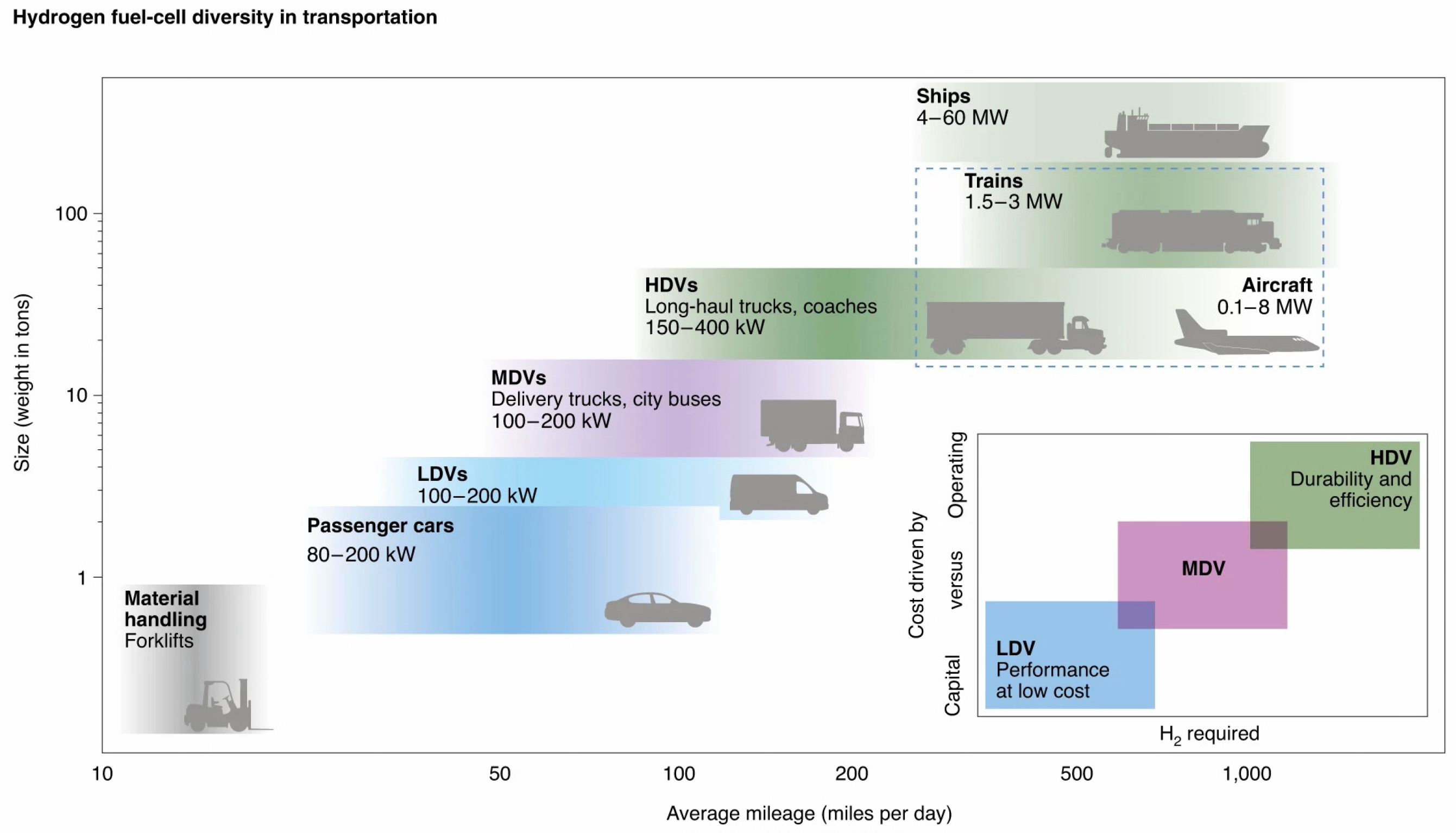
Figure 2.
Schematic of a PEMFC with a coolant channel system embedded.
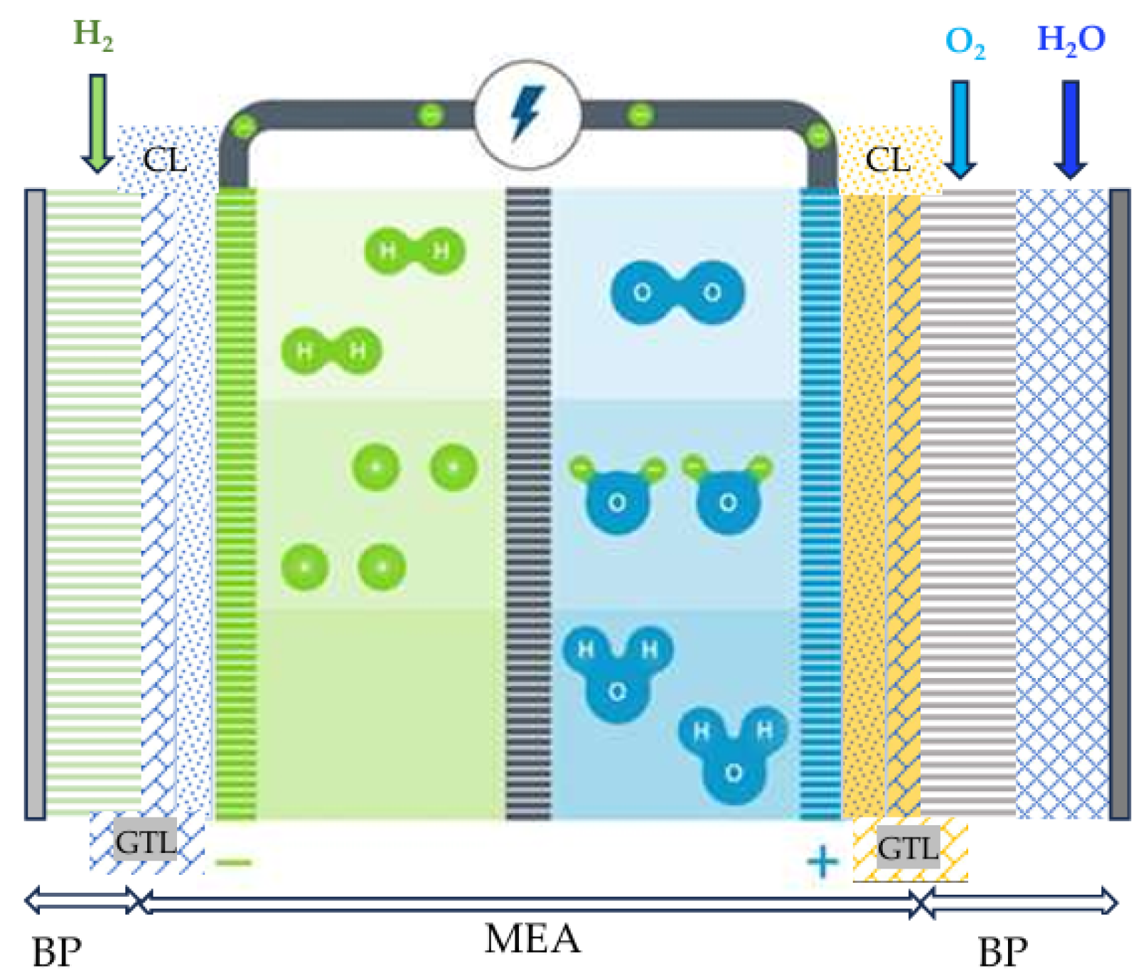
Figure 3.
Fuel cell performance influencing factors vs current density reprinted from Ref. [40,43,44,45].
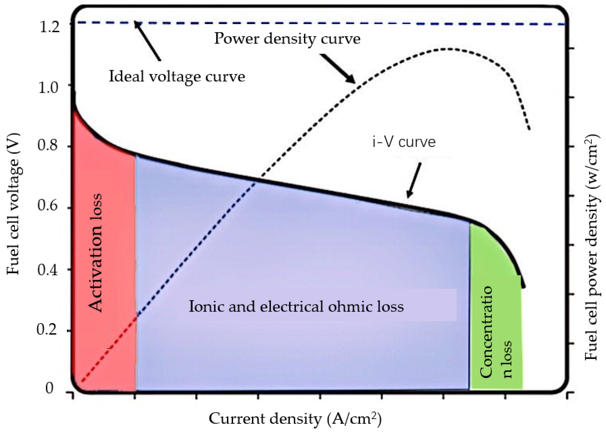
Figure 4.
A typical fuel cell vehicle powertrain layout reprinted from Ref [46].
Figure 4.
A typical fuel cell vehicle powertrain layout reprinted from Ref [46].
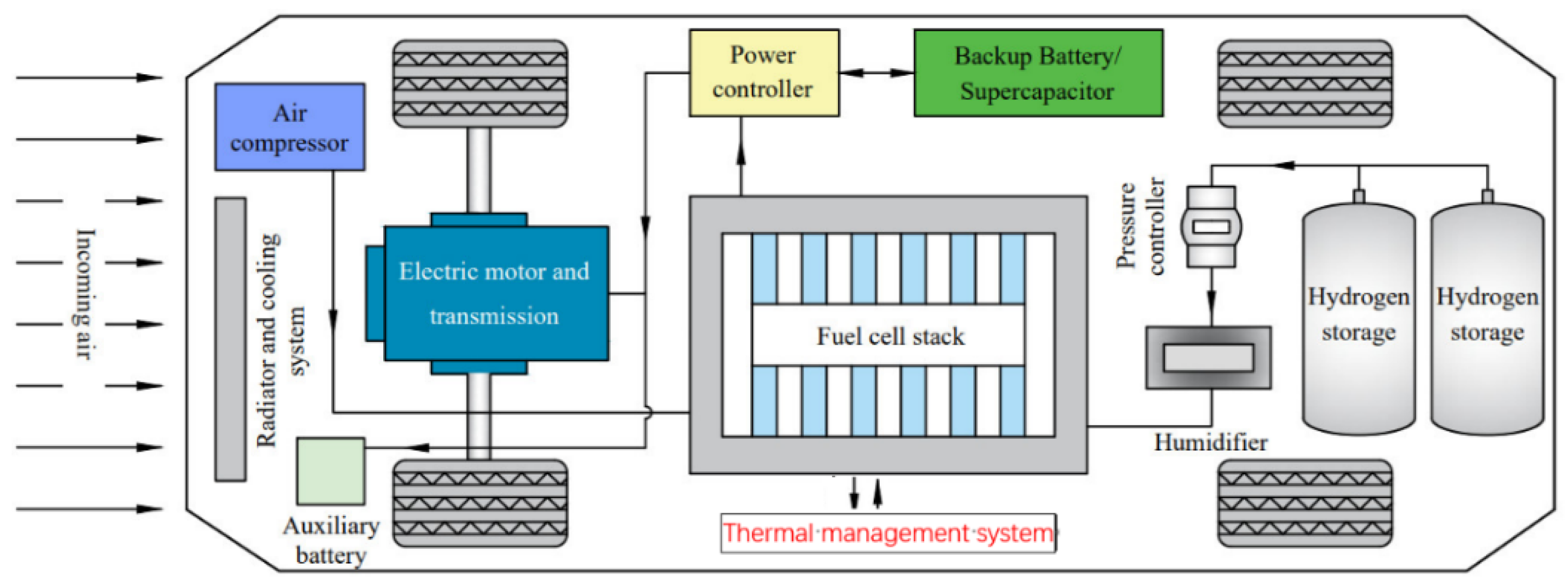
Figure 5.
Fuel cell stack efficiency, system efficiency vs power distribution in Toyota Mirai fuel cell vehicle (model year: 2016) at chassis dynameter conducted by America DOE) [7].
Figure 5.
Fuel cell stack efficiency, system efficiency vs power distribution in Toyota Mirai fuel cell vehicle (model year: 2016) at chassis dynameter conducted by America DOE) [7].
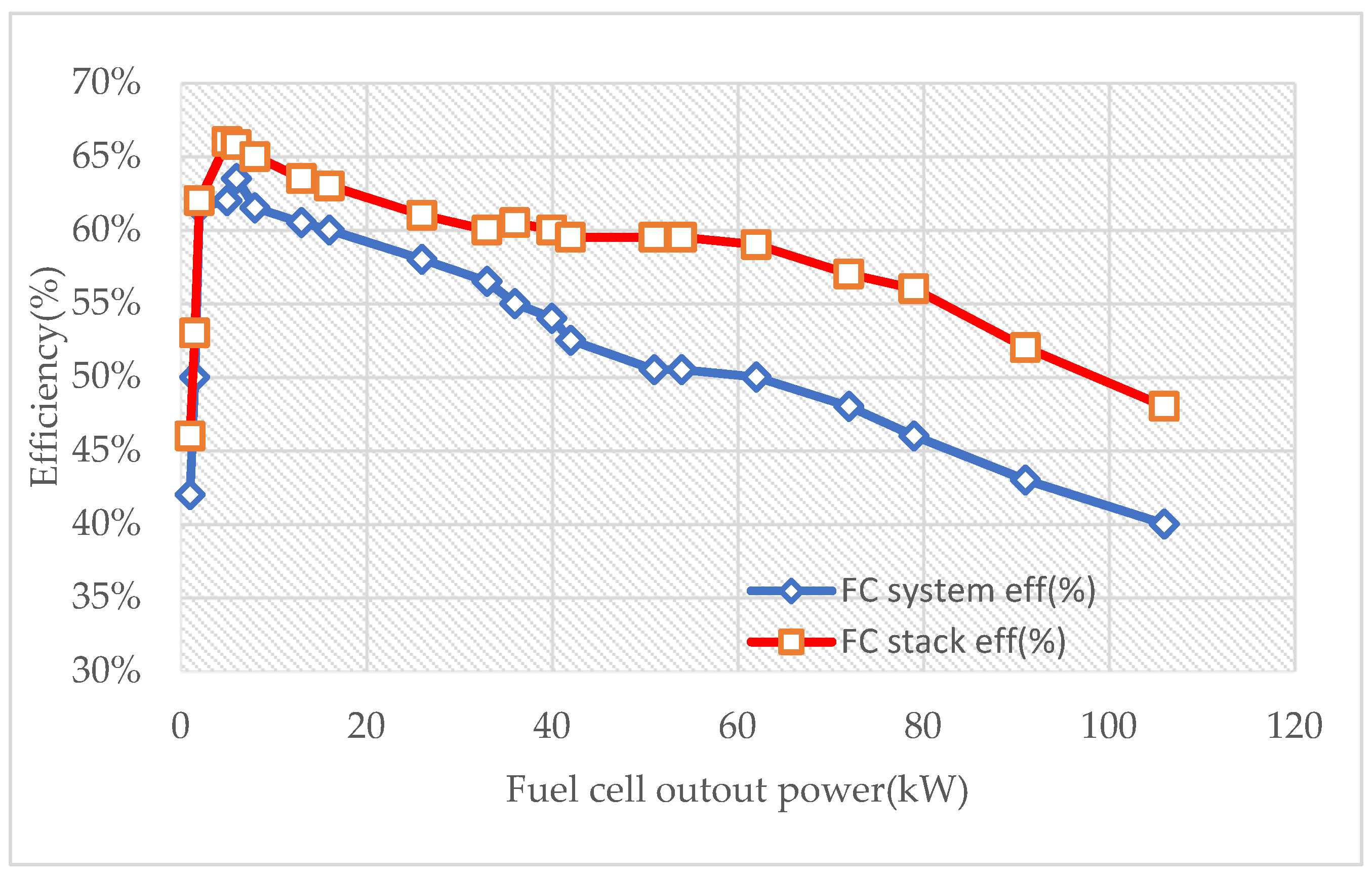
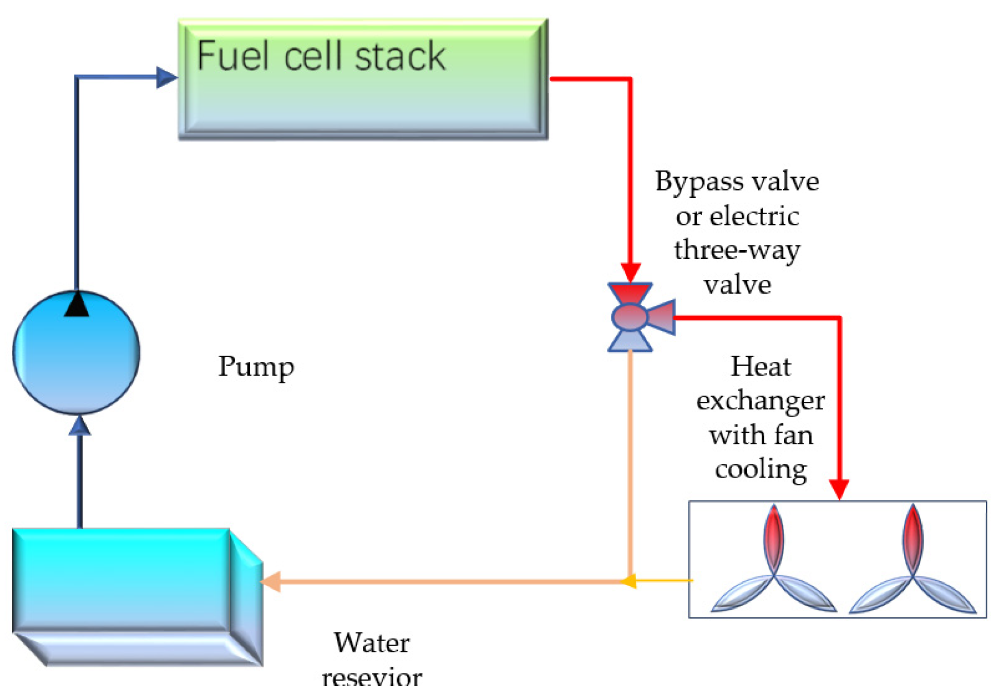
Figure 7.
Measured fuel cell stack and system efficiency under varied temperature setting: (a) conditions in the tests (b) Measured Efficiency with varied current and temperature [71].
Figure 7.
Measured fuel cell stack and system efficiency under varied temperature setting: (a) conditions in the tests (b) Measured Efficiency with varied current and temperature [71].
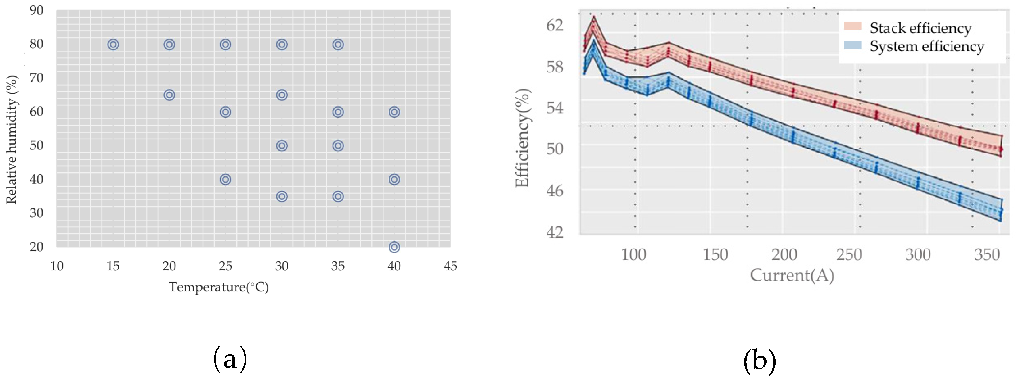
Figure 8.
Temperature distribution across a PEMFC stack were obtained by modeling for liquid cooling, the inset in (b) shows the voltage output of every single cell [76,77].
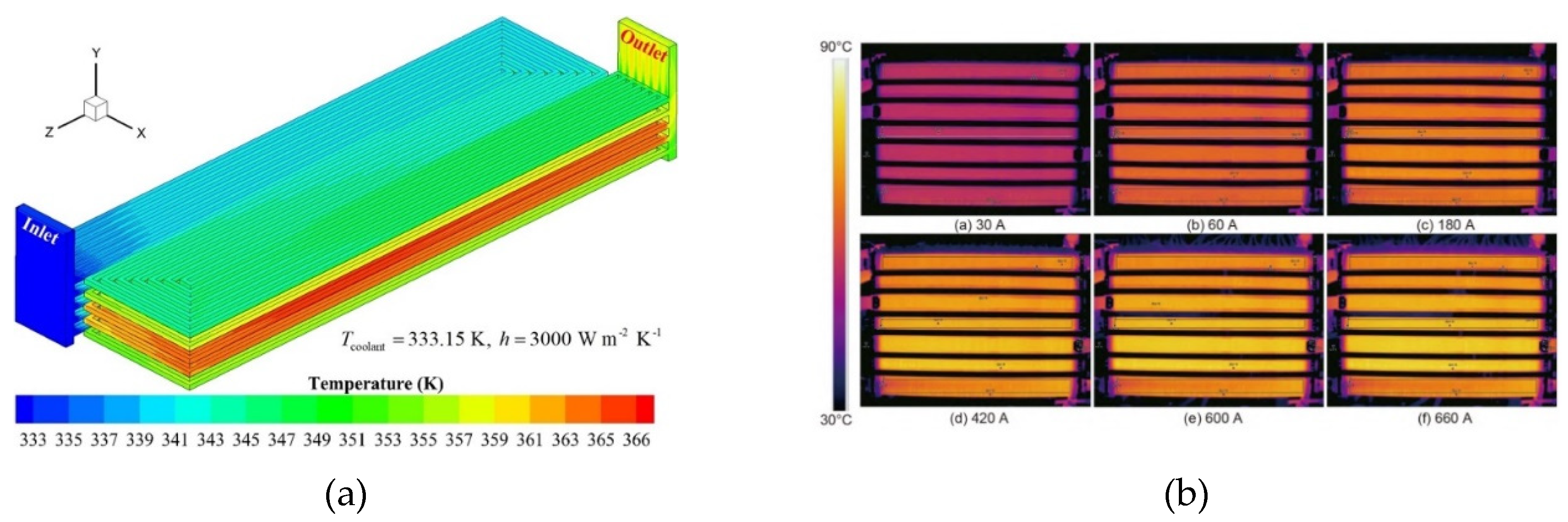
Figure 9.
Comparison of the I-V curve prediction between the ANN+ GA and three-dimensional multi-physics simulation [79].
Figure 9.
Comparison of the I-V curve prediction between the ANN+ GA and three-dimensional multi-physics simulation [79].
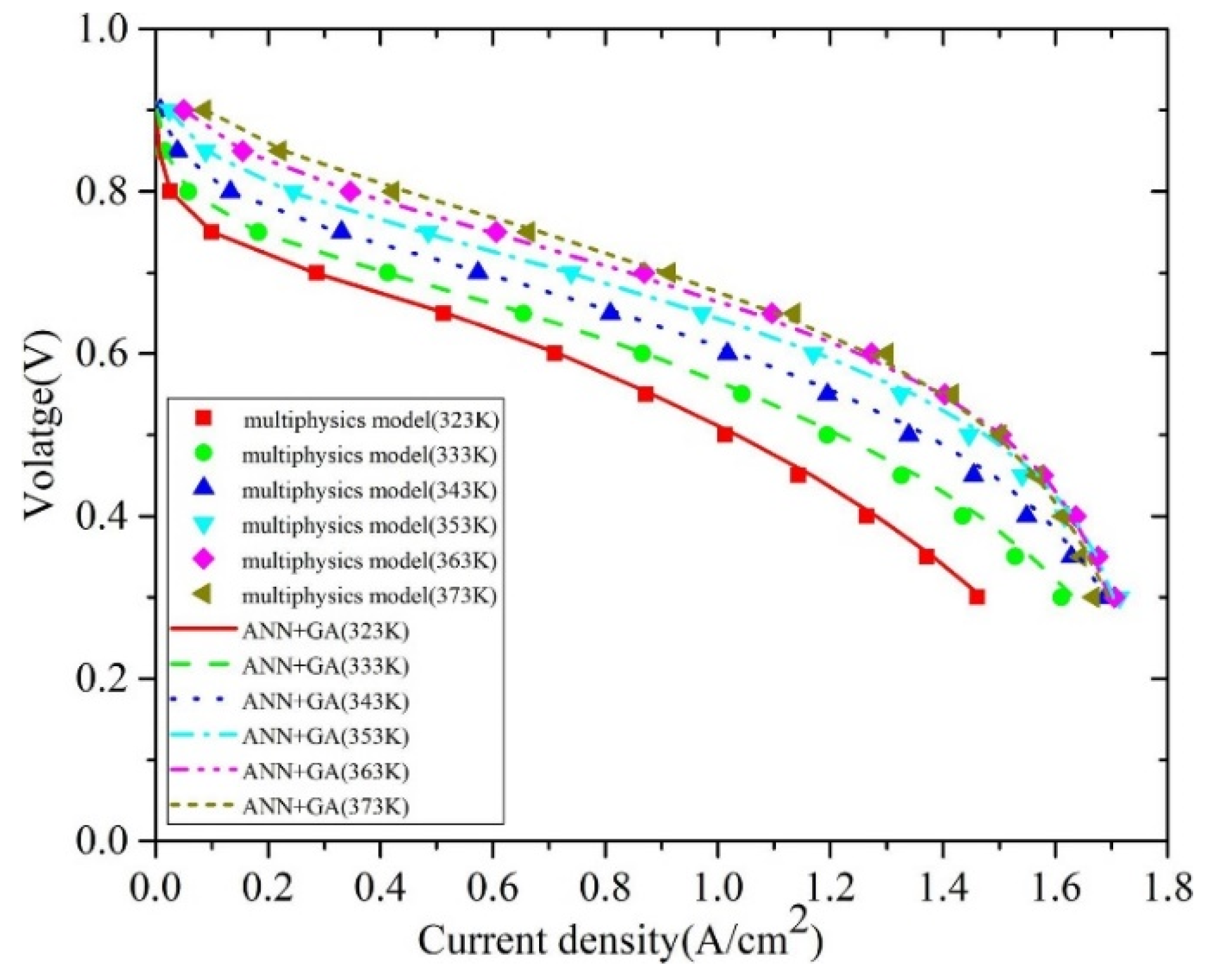
Figure 10.
An LQR based state feedback control combined with PI control for optimization of parasitic power in a 75 kW PEMFC [83].
Figure 10.
An LQR based state feedback control combined with PI control for optimization of parasitic power in a 75 kW PEMFC [83].
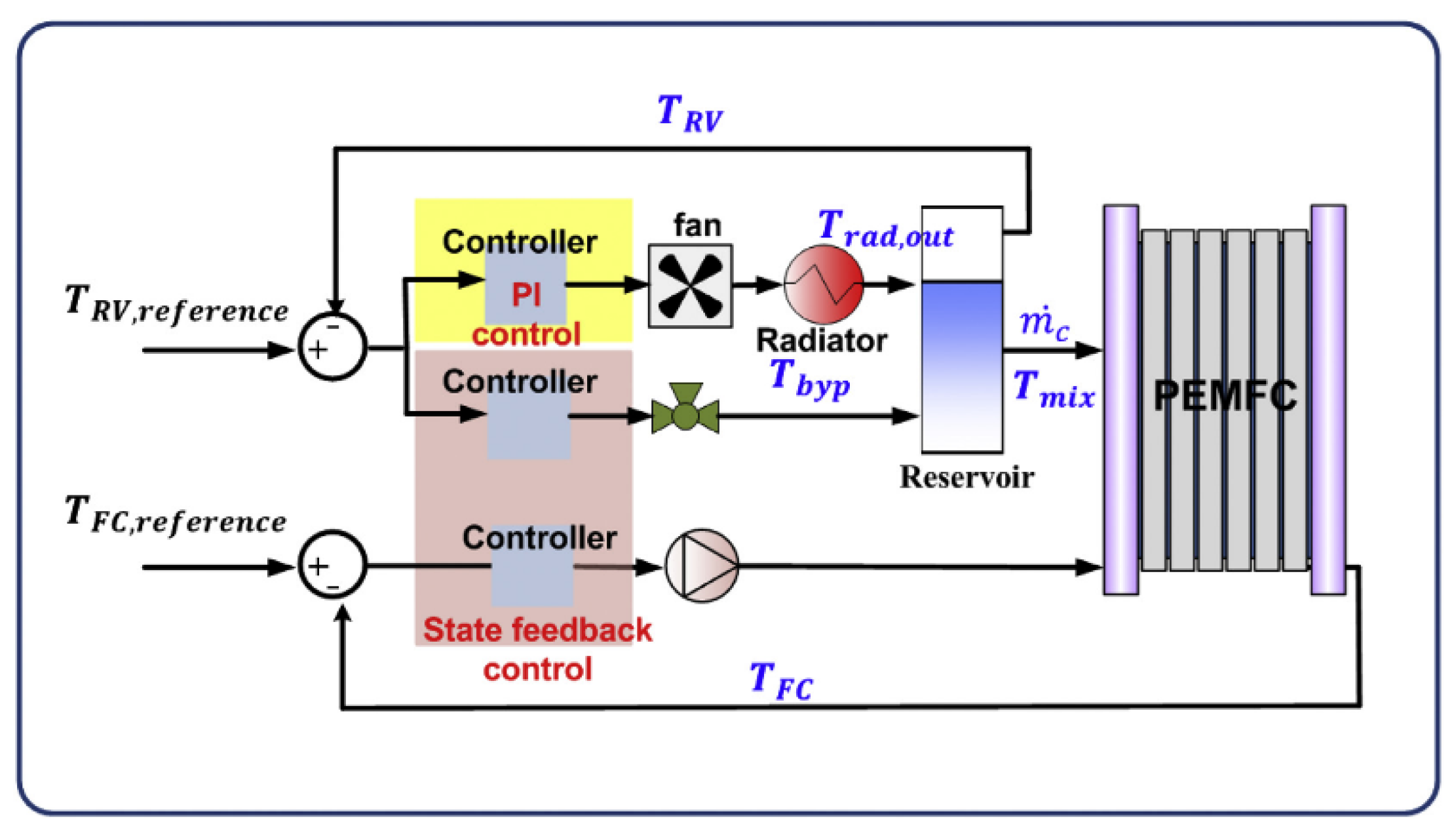
Figure 11.
Waste heat utilization in a fuel cell electric vehicle (FCEV).
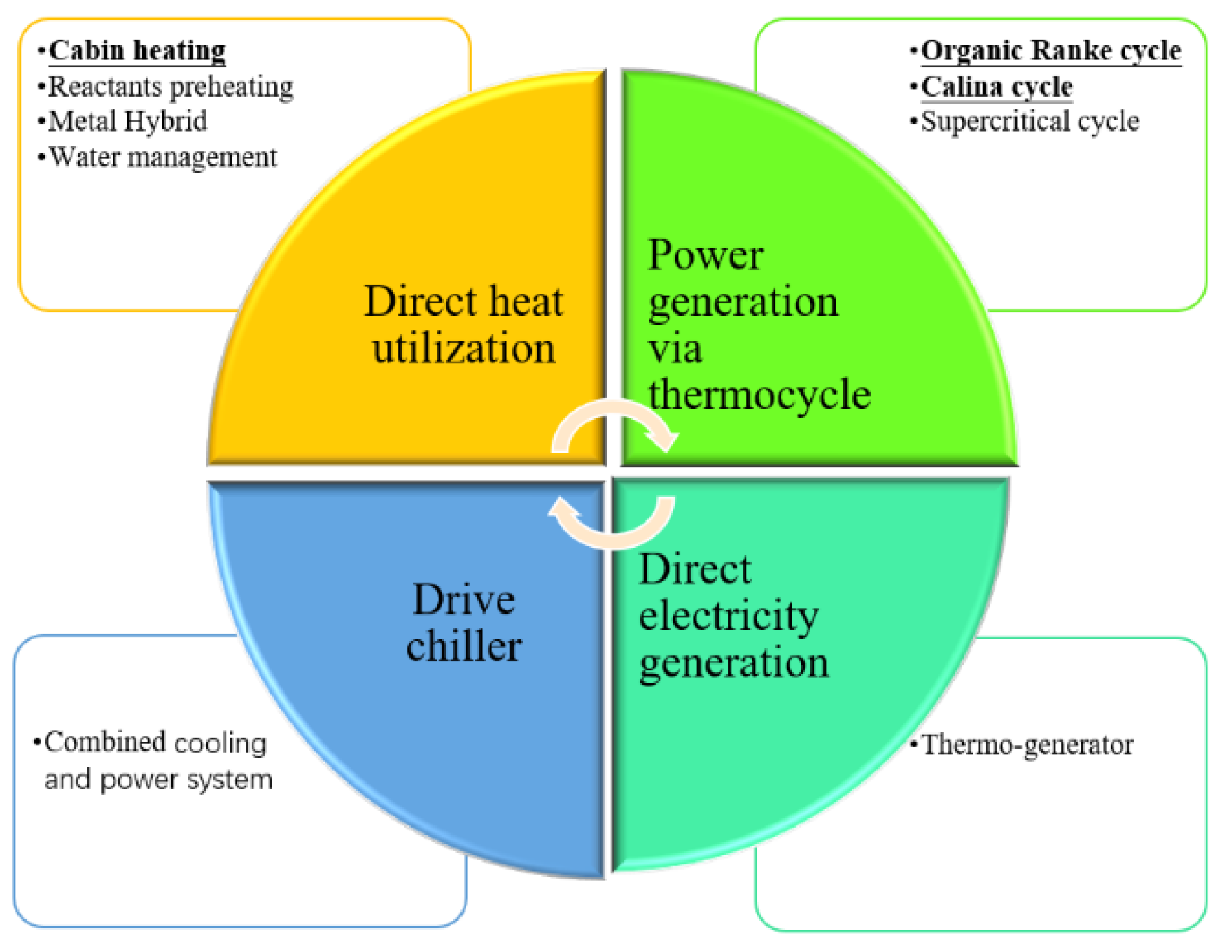
Figure 12.
Typical Sankey Diagram of a PEMFC power flow distribution [50].
Figure 12.
Typical Sankey Diagram of a PEMFC power flow distribution [50].
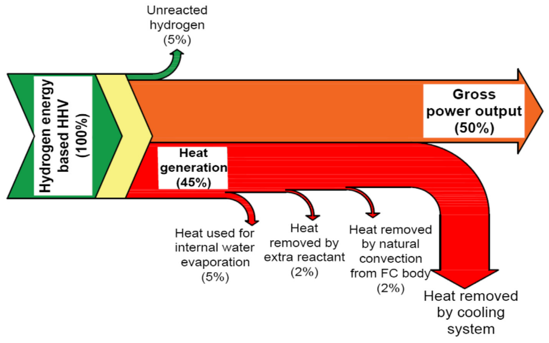
Figure 13.
ORC system efficiency as a function of Carnot efficiency [93].
Figure 13.
ORC system efficiency as a function of Carnot efficiency [93].
Disclaimer/Publisher’s Note: The statements, opinions and data contained in all publications are solely those of the individual author(s) and contributor(s) and not of MDPI and/or the editor(s). MDPI and/or the editor(s) disclaim responsibility for any injury to people or property resulting from any ideas, methods, instructions or products referred to in the content. |
© 2024 by the authors. Licensee MDPI, Basel, Switzerland. This article is an open access article distributed under the terms and conditions of the Creative Commons Attribution (CC BY) license (http://creativecommons.org/licenses/by/4.0/).
Copyright: This open access article is published under a Creative Commons CC BY 4.0 license, which permit the free download, distribution, and reuse, provided that the author and preprint are cited in any reuse.


