1. Introduction
The ever-increasing development of wireless communications has led to a large number of radio standards “coexisting” today [
1]. Connected objects (PCs, cell phones, connected sensors, Wi-Fi routers, Bluetooth headphones, etc. ...) often incorporate several radio frequency technologies for different purposes, using different frequency bands [
2]. In particular, the antenna, which is one of the main and indispensable components of any radio node, imposes significant physical constraints due to its size and the need to isolate it from any other radiating elements present and from other components operating in baseband. Numerous techniques have been developed to miniaturize antennas [
3], and to make them more polyvalent in terms of usable frequency bands (i.e., operational in several bands) [
4].
More recently, electromagnetic energy recovery devices are also attracting increasing attention. The omnipresence of radiofrequency waves in our environments makes it possible to use them (without degrading their primary function of transmitting information for a given standard) to provide a source of energy which, after RF-dc conversion, can be used to power low-energy devices such as sensors [
5]. In this context, too, the antenna's size and versatility in terms of frequency bands are important assets. In particular, the multiband nature of antennas makes them more robust over time (or even space, if the device is mobile) in radiofrequency environments that can fluctuate in terms of the frequencies present or their intensity [
6].
Finally, in both cases, wireless information transmission or wireless energy transfer, having a single antenna, then of the multiband type, is also an advantage in terms of cost and ecological footprint compared to a dedicated narrow-band multiple-antenna solution.
The aim of the study presented here is to design a dual-band antenna operating at ISM frequencies 2.45 GHz and 5.8 GHz, targeting, for example, common WLAN standards such as Bluetooth, Wi-Fi and Wi-MAX. More specifically, in addition to an antenna operating at these two frequencies, we are looking for a good compromise between performance, size and cost.
Section 2 describes the initial choices made and the step-by-step methodology followed, with particular emphasis on optimization.
Section 3 focuses on the impact of the slots and notches created at the various stages of antenna design, with the antenna's reflection coefficient as the main criterion. In
Section 4, the manufactured prototype is experimentally characterized, showing good agreement with the simulations presented.
Section 5 gives a comparative overview with antennas of the same type from the literature.
Section 6 concludes the study and opens up a few perspectives.
2. Dual-Band Antenna Design and Simulations
2.1. Technical Specifications and Choice of Antenna Type
The objective of the design is to provide a compact, low-cost, dual-band antenna operating at 2.45 GHz and 5.8 GHz, with high performance; more specifically, i) a reflection coefficient of less than10 dB, ii) a bandwidth of at least 100 MHz, iii) a gain of at least 2 dBi, and iv) an efficiency of at least 80% in both bands.
In the literature, there are several types of antenna for embedded applications, such as wire antennas [
7], aperture antennas [
8], metasurface reflectors [
9] or microstrip patch antennas [
10,
11]. In particular, patch antennas (or printed-on-substrate antennas) are designed chosen because they occupy little space in RF energy collection systems and can offer robust and inexpensive solutions. Patch antennas consist mainly of a radiating element, commonly called a patch, a substrate and a ground plane. Antennas with thick, low-dielectric-constant substrates offer higher efficiency, greater bandwidth and fields that are less restrictive to radiation in space. On the other hand, antennas with thin substrates and high dielectric constants result in high losses and low bandwidth. Several types of substrates are often used to design patch antennas: Rogers [
11], Epoxy Flame Retardant-4 (FR-4) [
12], PEC [
13], Teflon [
14], Textile [
15], and RT Duroid [
16]. Flexible substrates such as polydimethylsiloxane (PDMS) and PF4-foam materials [
17] are also used. However, the most commonly used substrate is FR-4 epoxy, due to its low cost, easy to manufacture, suitable for mass production, and relative high performance. Besides, FR-4 is highly water-resistant and does not absorb moisture. Small patch antennas generally have low gain and reduced bandwidth. To improve the performance of these antennas, notably in terms of gain and efficiency, slots can be inserted in the radiating element [
18,
19,
20]. Consequently, in order to obtain a low-cost, relatively compact, and high-performance antenna, a microstrip patch antenna integrating slots based on a FR-4 substrate is chosen for this work.
2.2. Proposed Antenna Configuration
First, it should be noted that all the simulation results presented were obtained using the high-frequency simulation software HFSS-version 13.0.
The proposed antenna is rectangular in shape and fed by a centered microstrip line. The advantage of choosing a rectangular shape is that rectangular patch antennas can be sized according to theoretical equations [
21]. The radiating element and ground plan have a thickness of 0.035 mm which represents the most economical standard PCB (printed circuit board) thickness. The substrate used for the antenna design (FR-4 epoxy) has a relative permittivity of 4.4, a loss tangent of 0.02 and a thickness of 1.6 mm. For simplicity's sake, the feed line is a microstrip placed in the same plane as the radiating element.
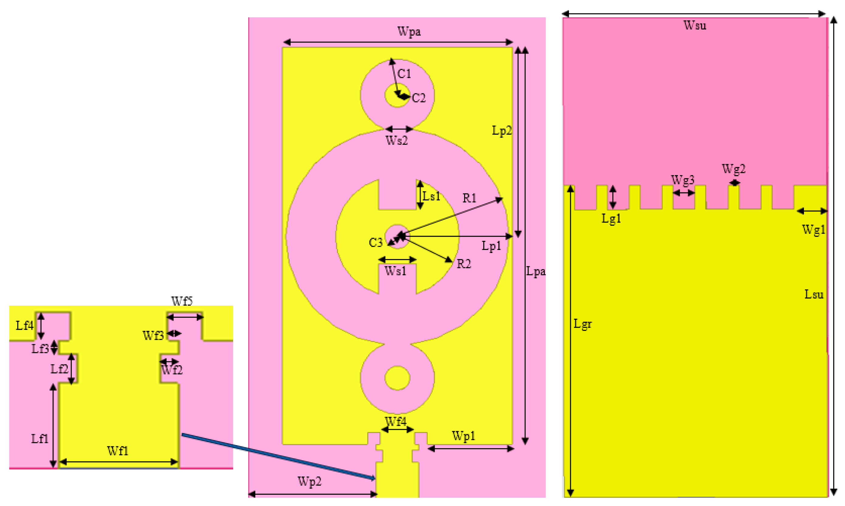
The proposed antenna configuration after optimization steps is shown in
Figure 1. The antenna features circular and rectangular slots on the patch. Notches are inserted on the feed line, and the partial ground plane has a crenelated shape at the top.
Table 1 presents the dimensions of each element of the antenna (slots, patch, feed line, substrate and ground plan). The optimized dimensions of the patch (Lpa × Wpa) and substrate (Lsu × Wsu) are 33 mm × 18.5 mm and 40 mm × 24 mm respectively.
2.3. Antenna Design Methodology
To size the antenna, a frequency of 2.45 GHz is initially chosen. In fact, an antenna whose dimensions are obtained from a given frequency is capable of operating in higher frequency bands. As with any antenna, there is not just one resonant frequency, but many multiples of it. From [
21], considering the previous parameters and the low frequency (i.e., 2.45 GHz), the dimensions of the patch (Lp × Wp) and the ground plane (Ls × Ws), here identical to those of the substrate are equal to 37.23 mm × 28.81 mm and 46.23 mm × 38.41 mm respectively. One technique for making other main resonances appear (which can also be repeated on even and odd multiples) and minimize the antenna size would be to insert slots on the antenna. Our aim is to introduce the second 5.8 GHz frequency band and optimize the antenna’s performance. The optimization objective was constrained by the conditions i) to iii) set out above.
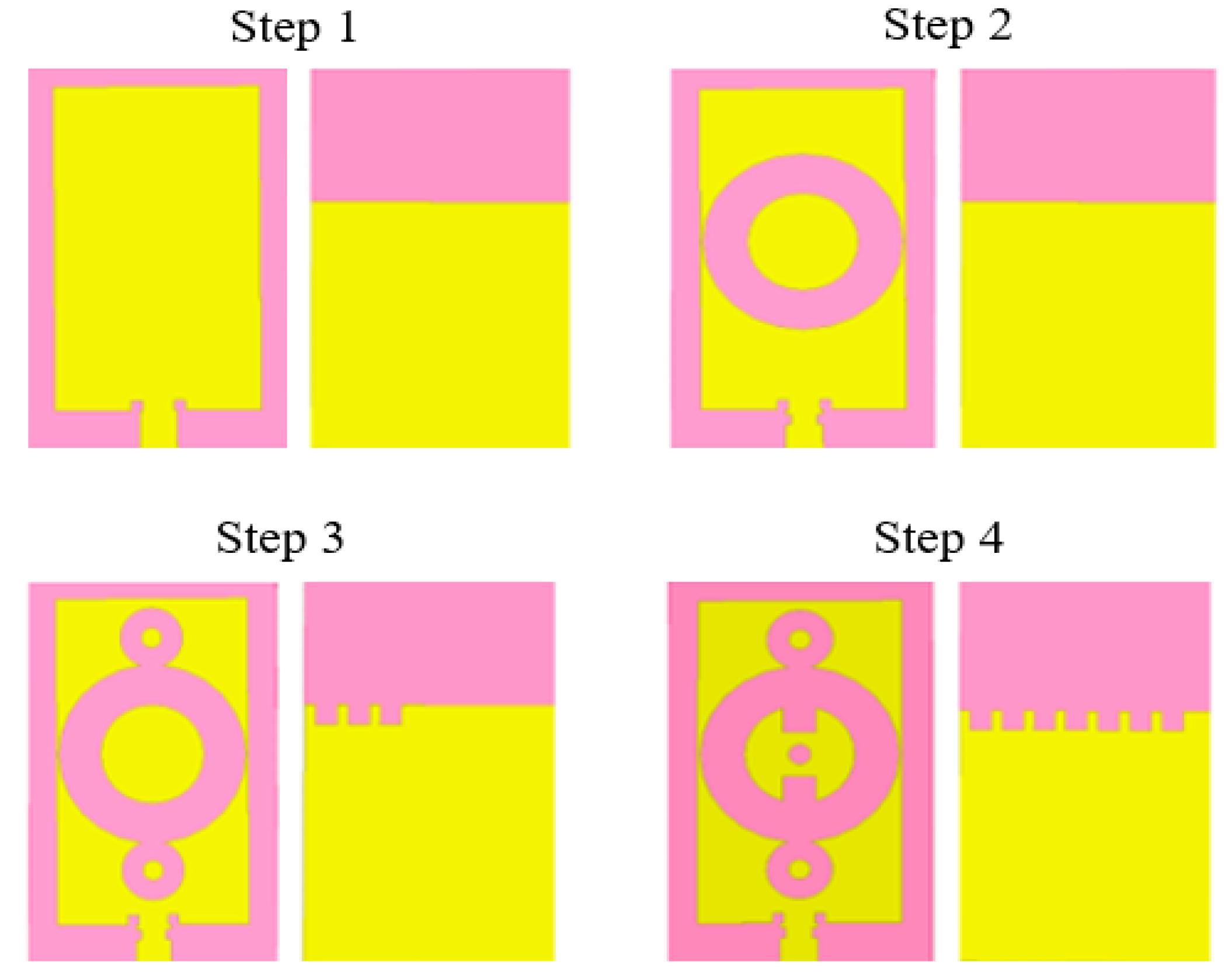
Figure 2 shows the four different steps in the antenna design process. Initially, in step 1, the ground plan is modified by reducing its length, followed by the insertion of a pair of 1 mm × 1 mm square notches at the intersection of the patch and the supply line. These notches and the partial ground plan are proposed to improve the antenna's reflection parameters and minimize its size, inspired by the authors' work in [
21]. In step 2, a circular ring is introduced on the patch and a second pair of 1 mm × 0.5 mm rectangular notches is then inserted in the lower part of the feed line. Three 2 mm × 2 mm square slots and two circular slots are inserted in the upper part of the ground plan and symmetrical to the central ring in the third step respectively. The final antenna is obtained by adding three slots to the patch, two of which are rectangular. The ground plan is also modified by creating four another square slots in its upper part. The idea behind the shape of the ground plan and the slots is to create a new current distribution that would influence the resonant frequencies obtained (better antenna matching by frequency shifting) and improve the antenna's bandwidth.
The circular and rectangular slots are inserted to considerably increase the distance that the surface current would travel across the patch. Indeed, a current flowing from one end of the patch to the other is generally blocked by the slots. To bypass them, it will have to take a longer path than the one without the slots inserted, which would increase the length covered by the current. The result would be a lengthening of the wavelength or a reduction in the antenna's operating frequency. This technique can be used to reduce operating frequencies or shift the frequency of resonance points.
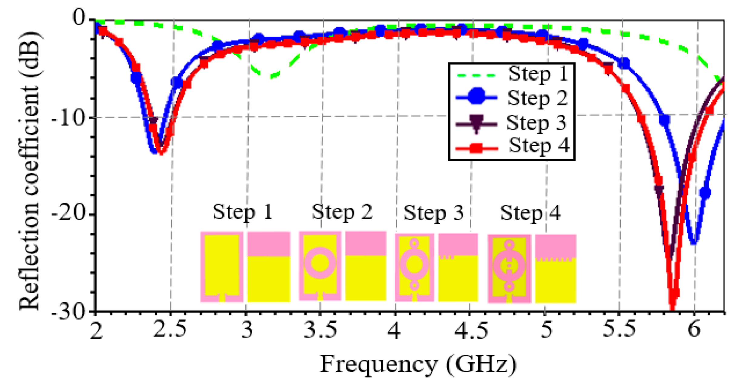
The antenna's reflection coefficient at the four steps is shown in
Figure 3. It should be noted that the frequency bands obtained after simulation of the antenna corresponding to the initial structure (step 1) are not adapted to ISM frequencies. At design step 1, the antenna has two desired operating frequencies, but with a significant frequency offset, namely 3.1 GHz and 6.8 GHz (not visible on the curve, as this latter frequency is not of interest here), and a reflection coefficient greater than
10 dB (
6.2 dB) at 3.1 GHz. In step 2, the antenna has two frequency bands very close to the two ISM bands, i.e., 2.41 GHz and 6 GHz. At these frequency bands, the reflection coefficient is less than
10 dB. Step 3 of the design resulted in the two desired ISM frequency bands. Finally, in step 4, an improvement in antenna impedance matching and bandwidth around the two ISM center frequencies is observed.
Table 2 shows the antenna performance parameters at optimization steps 2 to 4. From the first to the last optimization step, there is a 77% and 30% increase in bandwidth at frequencies of 2.45 GHz and 5.8 GHz respectively.
3. Parameters Study
3.1. Impact of Circular Ring Radius at Design Step 2
The antenna structure in step 2 is obtained by inserting the slots on the feed line and then modifying the dimensions and position of the circular ring inserted. It should be noted that the notches had little effect on the frequency bands and reflection coefficients.
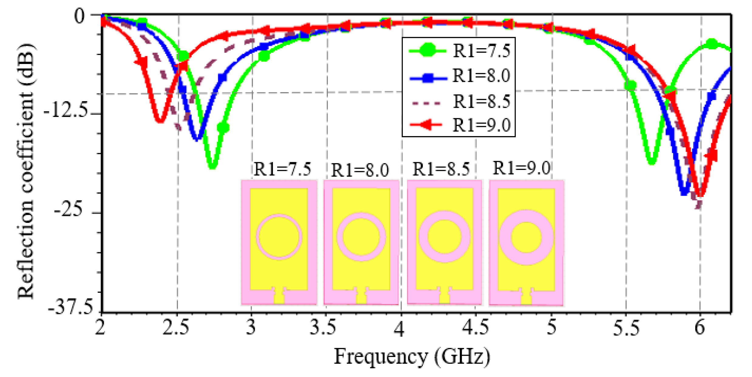
To study the impact of the ring’s dimensions on the reflection coefficient and the appearance of the second band observed, we assumed its fixed inner radius (
) and varied its outer radius (
) with a step of 0.5 mm. The reflection coefficient curve obtained is shown in
Figure 4.
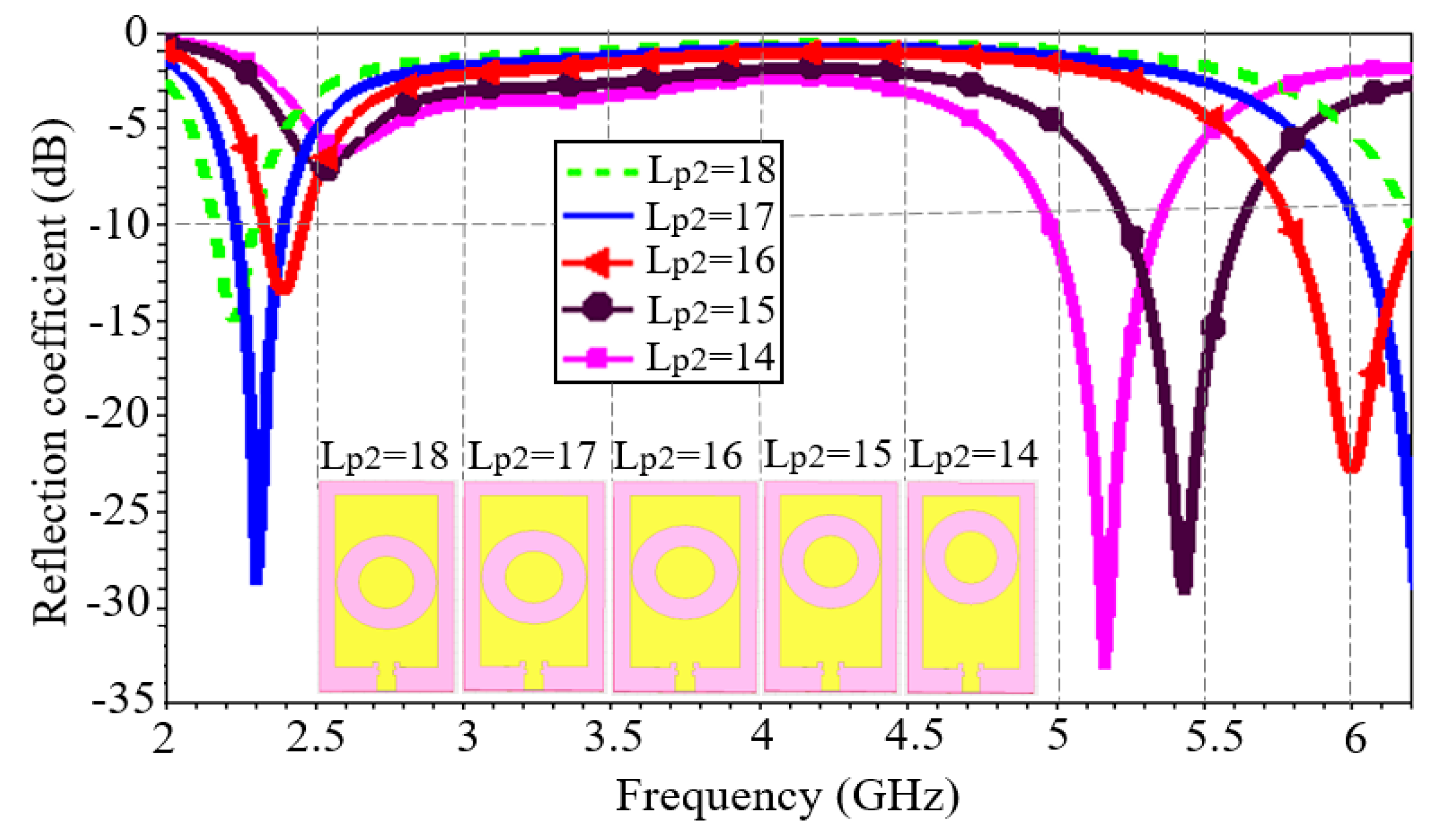
The insertion of the circular ring has enabled to obtain two frequency bands with a reflection coefficient of less than dB. Furthermore, as increases, a frequency shift towards the 2.45 GHz band is observed. Finally, for (which almost represents the outer limit of the ring), the antenna exhibits center frequencies of 2.41 GHz and 6 GHz.
In a second step, we studied the impact of the ring’s vertical position on the reflection coefficient. We fixed the radius of the ring obtained previously (
and
) and varied the distance
in 1 mm increment to determine the best vertical position for the ring.
Figure 5 shows the modulus of the reflection coefficient for different vertical positions of the ring. The study shows that as the distance decreases, there is a shift from high frequency (6 GHz) to low frequencies with a reflection coefficient whose modulus decreases; on the other hand, at low frequency (2.45 GHz) there is a slight shift to high frequencies with an increasing S11. The opposite phenomenon is observed as
increases. In other words, as the slot moves closer to the feed line, both frequencies below 2.45 GHz and above 6 GHz appear. Frequencies very close to the desired frequencies are obtained for
. In conclusion, modifying the vertical position of a slot on the patch can contribute to improving the antenna’s reflection coefficient performance.
The insertion of the circular ring slot in step 2 would therefore have led to a new distribution and concentration of current at points on the radiating element, resulting in a frequency shift and a frequency very close to the desired second frequency.
3.2. Impact of Created Slots in Steps 3 and 4
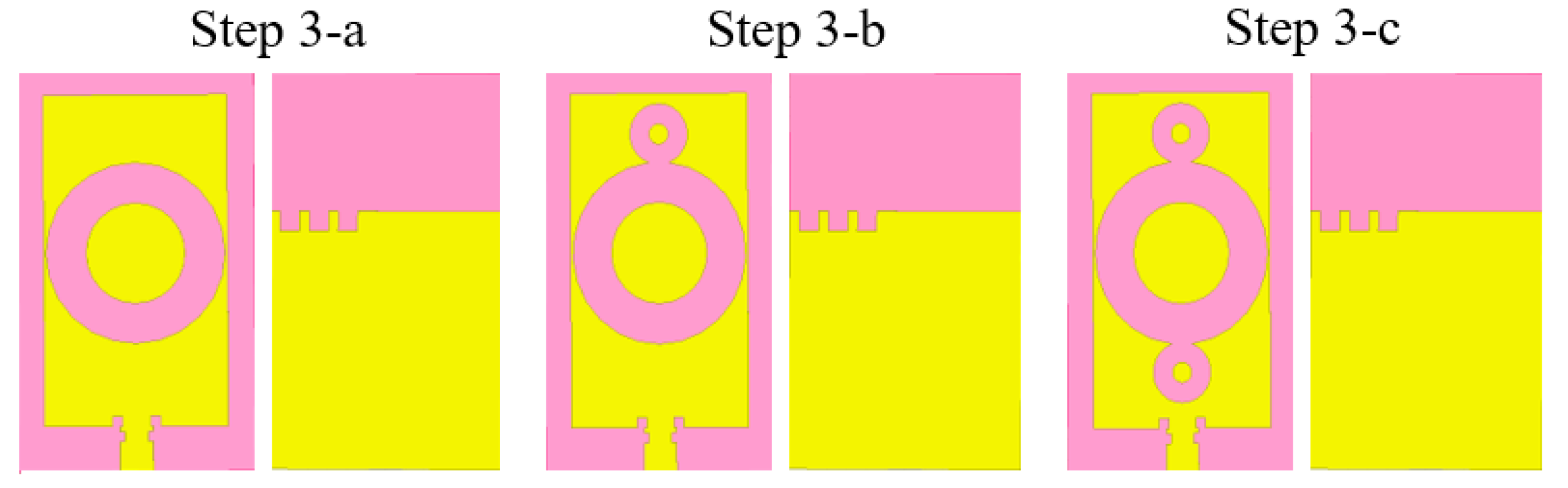
Figure 6 shows the various sub-steps involved in step 3 of the design. Step 3 consisted firstly in modifying the upper part of the ground plan (step 3-a) and then in successively inserting the two circular rings (steps 3-b and 3-c).
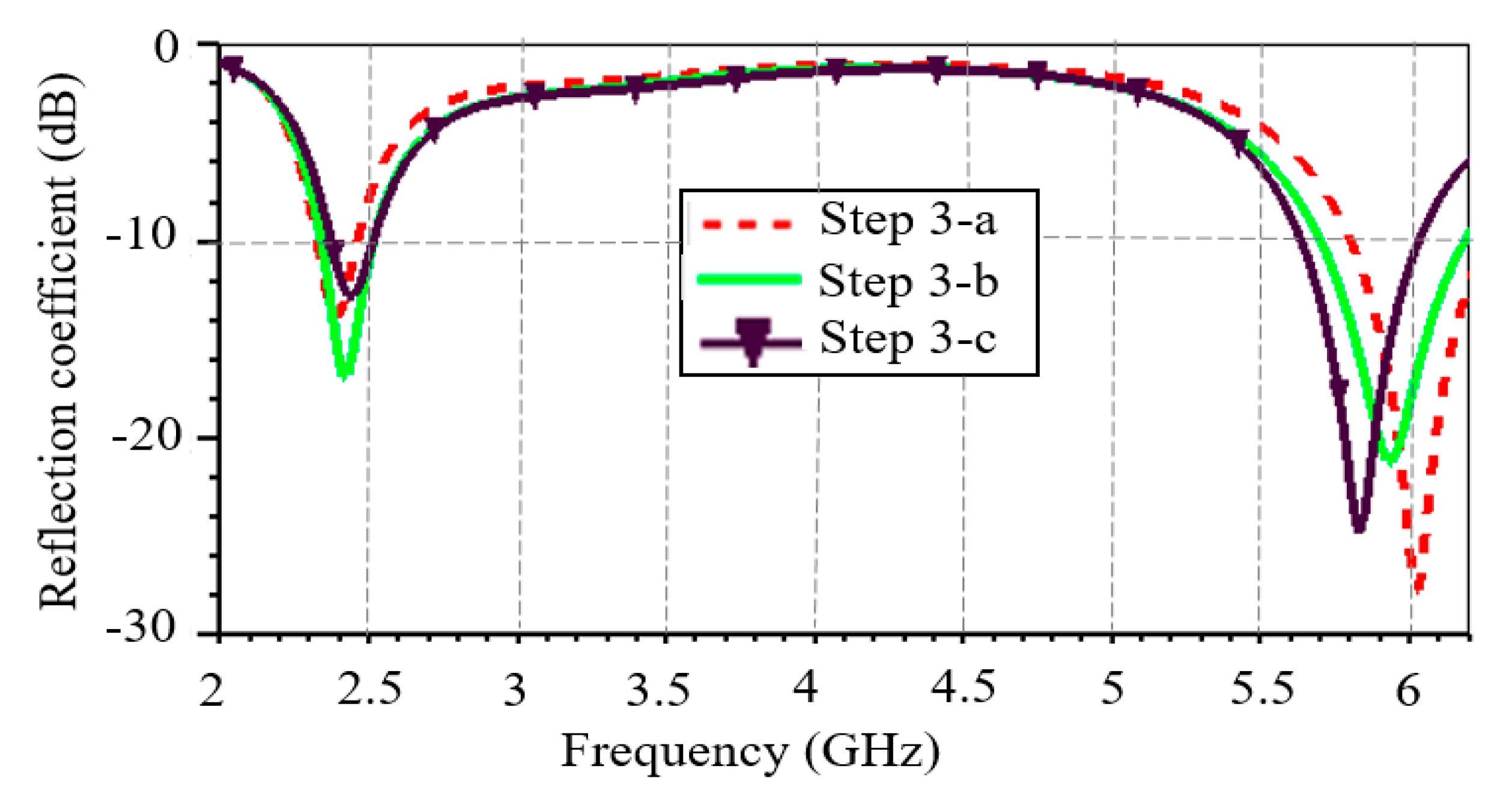
Figure 7 shows the evolution of the S11 in the various sub-steps. Firstly, the S11 improves after modification of the ground plan, compared with step 2 of the design (
16.48 dB vs.
13.76 dB at 2.41 GHz and
27.96 dB vs.
23.25 dB at 6 GHz). Insertion of the ground plane slots therefore improved the reflection coefficient without allowing a frequency shift around the 6 GHz frequency. The circular rings, on the other hand, enabled this frequency shift, resulting in the desired second frequency was obtained at the end of step 3.
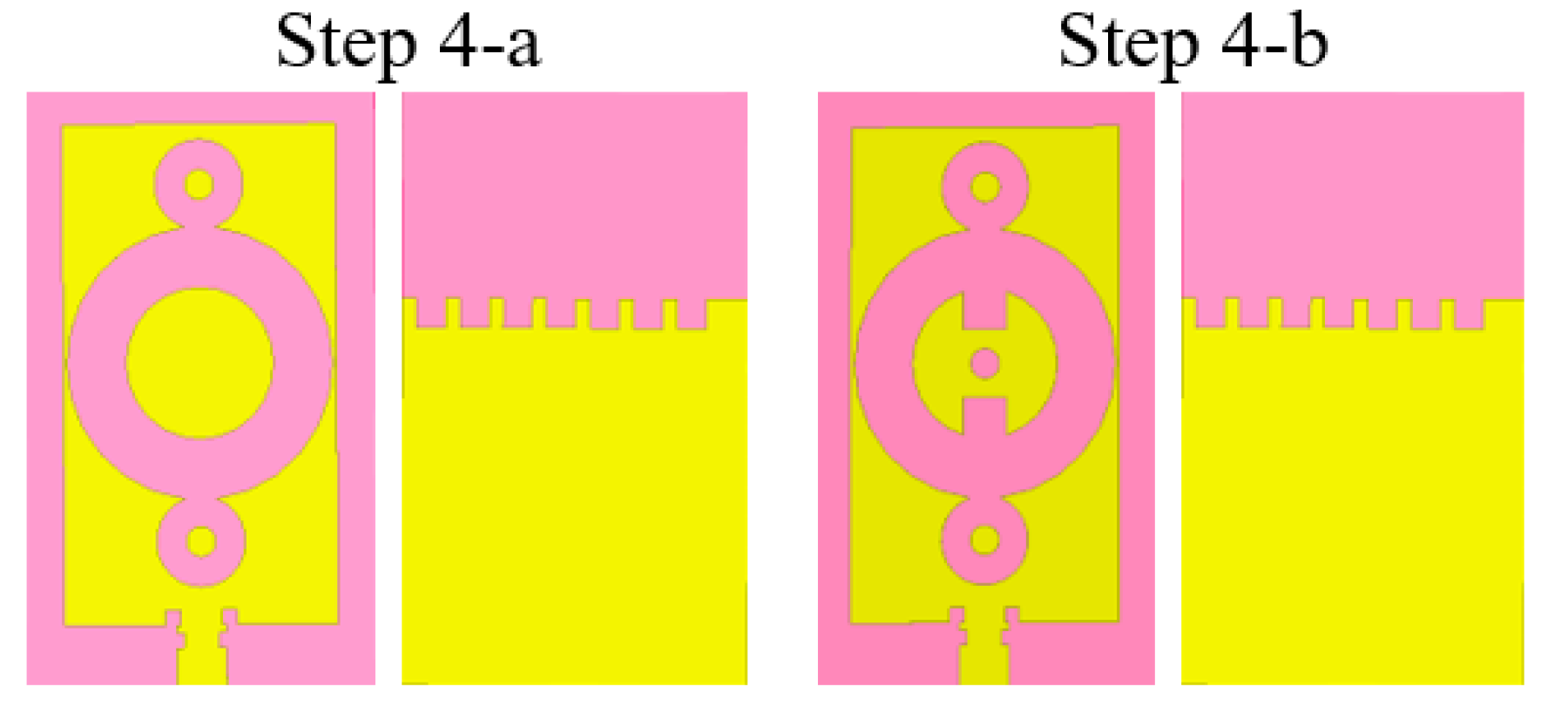
The positive influence of the ground plan slots on the S11 detected in step 3 made it possible to insert further slots to create a crenelated shape in the upper part of the ground plane, as shown in
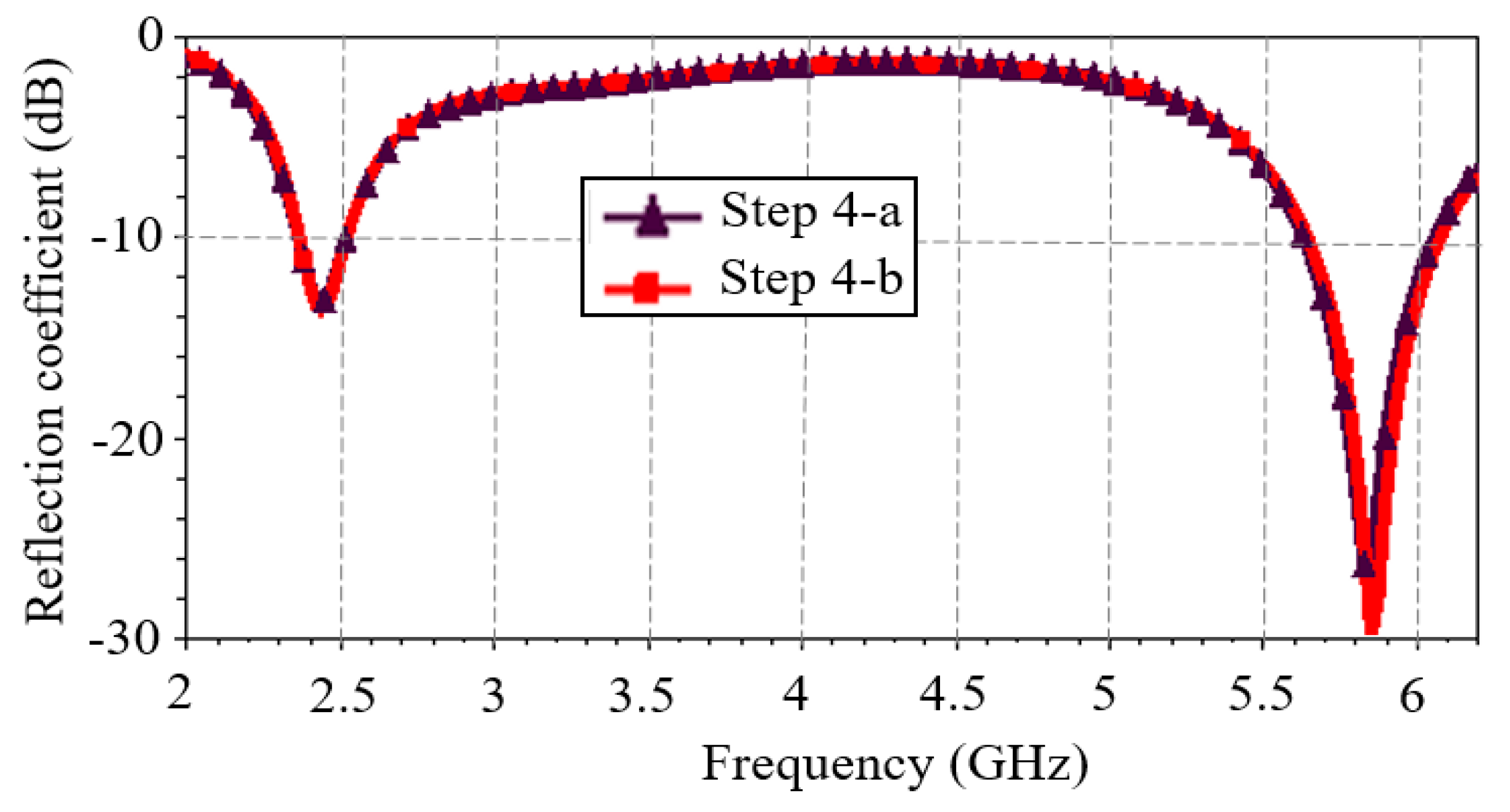
Figure 8 (step 4-a). The final optimization phase involved adding slots inside the central ring (step 4-b). The study of the S11 is presented in
Figure 9. S11 has been improved in the 5.8 GHz band with the addition of the patch slots. Compared with step 3, the added slots improved the antenna's S11 (
13.82 dB vs.
12.79 dB at 2.4 GHz and
29.73 dB vs.
24.81 dB at 5.8 GHz) and bandwidth by 14%.
The improvement in antenna bandwidth can be justified by the shape and positioning of the slots. Indeed, these two parameters would have induced capacitive and inductive effects in the antenna, which would have increased its bandwidth.
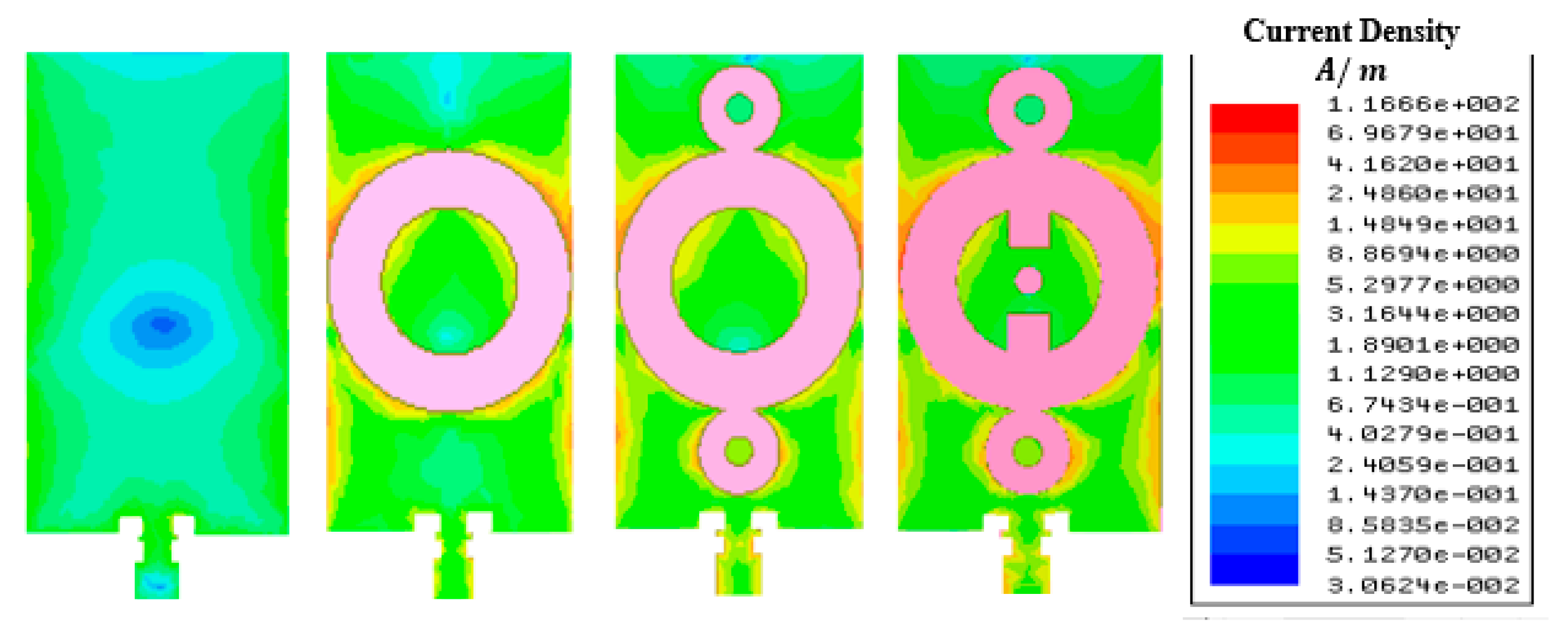
The observed reflection performance at the various steps of antenna design, and the symmetry of the antenna, can be justified by analyzing the surface current distribution on the patch.
Figure 10 shows the current distribution in the 2.45 GHz band at the various steps of antenna design. A gradual intensification of the patch current surface distribution, particularly around the slots is noted. No current is obviously observed in the slots. This shows that the surface current bypasses the slots. This current distribution on the patch is symmetrical. This observed symmetry is explained so by the symmetry of the antenna itself. Gradual intensification and symmetrical current distribution are also observed at 5.8 GHz. This current distribution explains why the slots on the patch were designed to improve the antenna's performance. Another antenna performance parameter is its radiation efficiency.
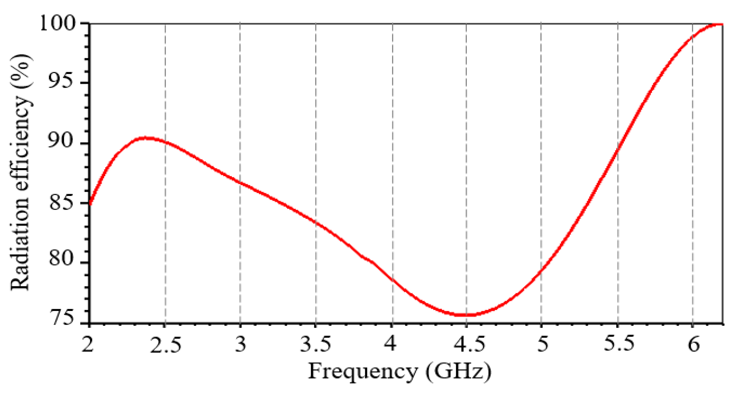
Figure 11 shows the antenna's radiation efficiency as a function of frequency. The dual-band antenna has a radiation efficiency of 90.3% and 96.2% at 2.45 GHz and 5.8 GHz respectively. In addition, the antenna reaches its maximum radiation efficiency around 2.45 GHz.
4. Experimental Results
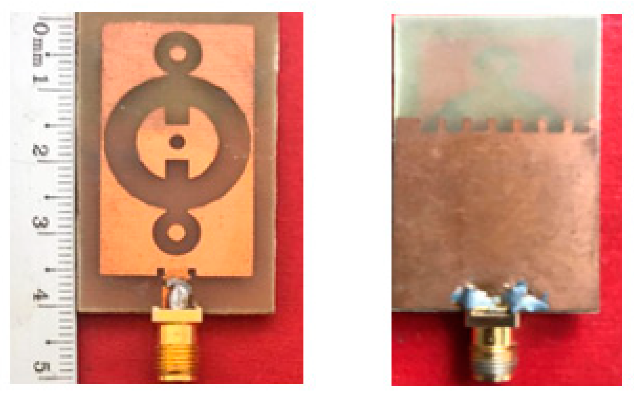
The proposed dual-band antenna is manufactured and experimentally characterized.
Figure 12 shows a photo of the front and bottom view of the fabricated dual-band antenna.
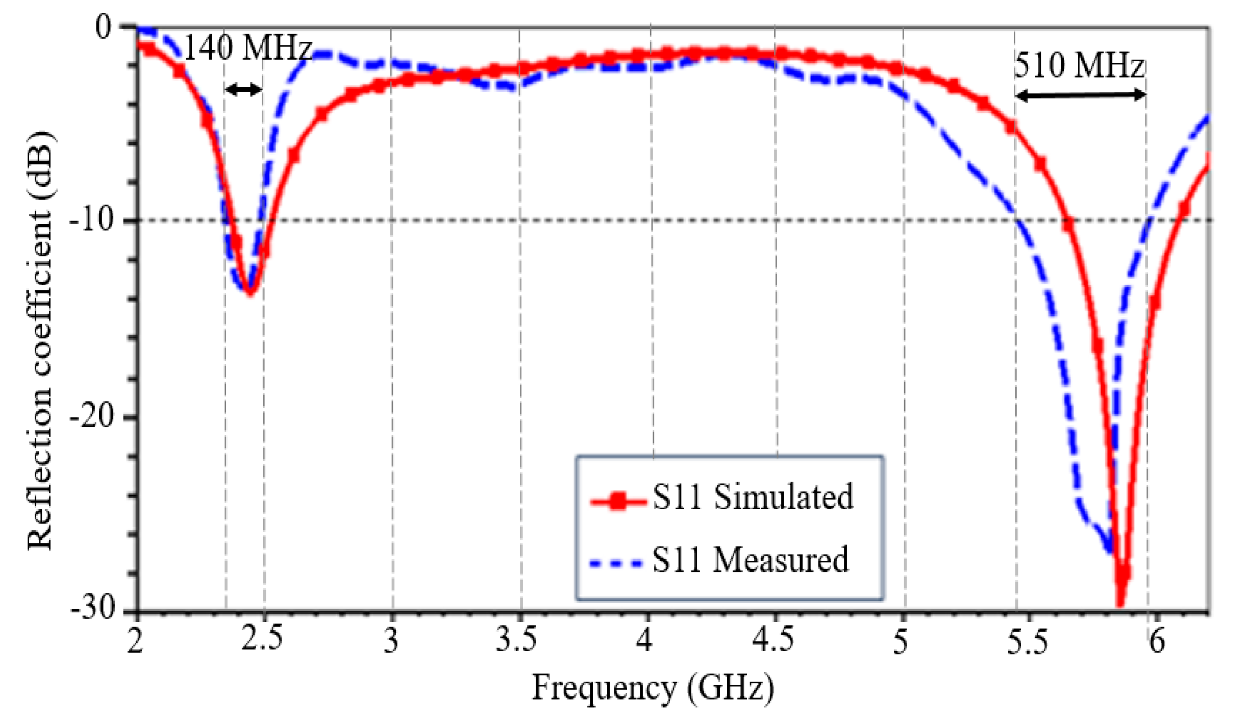
Figure 13 shows the simulated and measured reflection coefficient of the dual-band antenna as a function of frequency. The comparison results are detailed in
Table 3. The antenna operates under both frequency bands with a reflection coefficient whose threshold is less than
10 dB. There is a slight difference between the measured and simulated results, but the overall results agree well, validating the design as a whole.
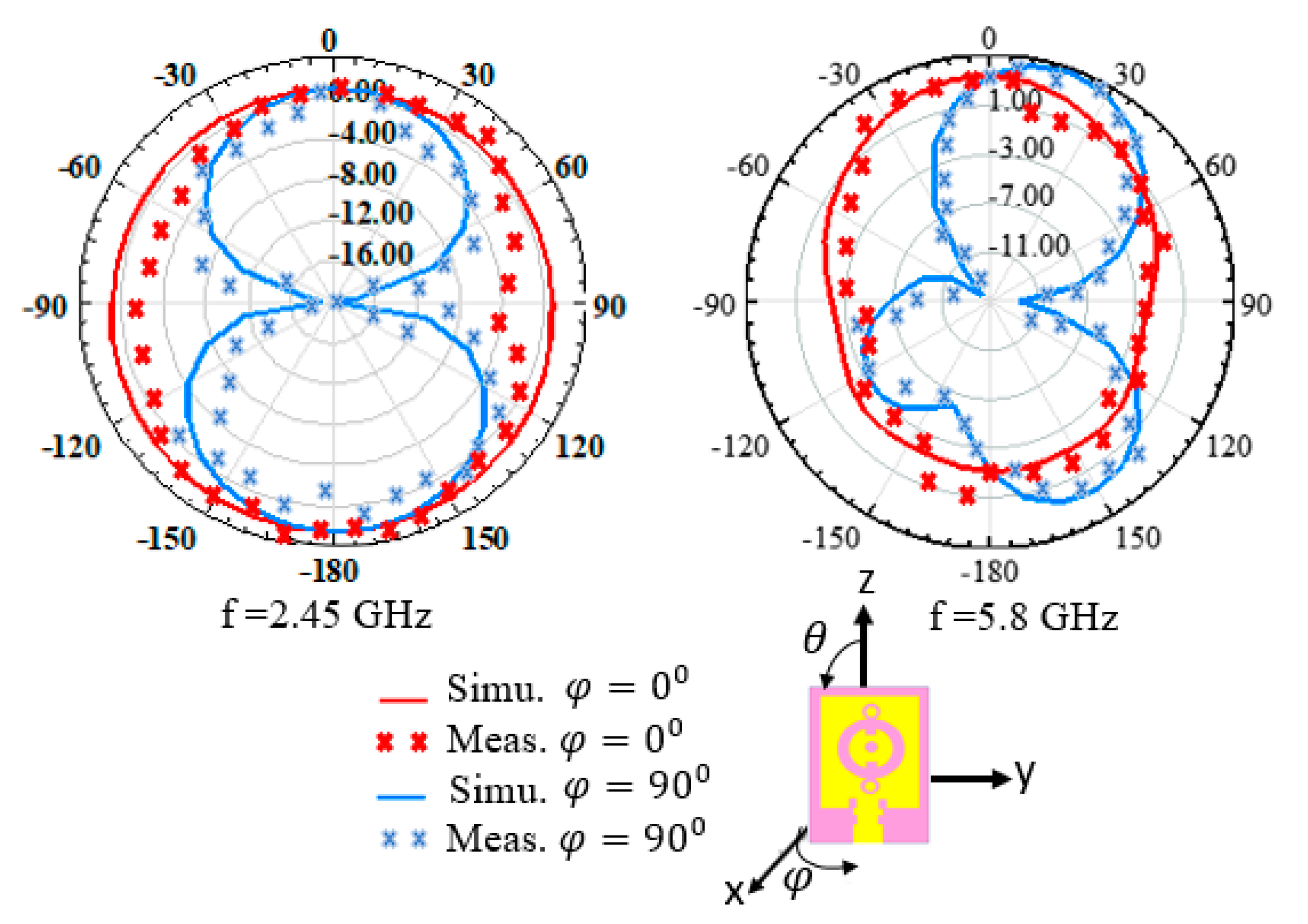
The simulated and measured antenna's radiation pattern at the two frequencies is shown in
Figure 14. A quasi-omnidirectional radiation pattern in the E plane (φ=0°) and directional in the H plane (φ=90°) are observed. Maximum gain is 2.41 dBi at 2.45 GHz and 5.22 dBi at 5.8 GHz.
5. Summary of Dual-Band Antenna Performance in Relation to the Literature
Several dual-band antennas operating in frequency bands of 2.45 GHz and 5.8 GHz have been already presented in the literature.
Table 4 presents a comparative study of the proposed antenna related to center frequencies, dimensions and antenna performances in terms of gain and radiation efficiency (for each frequency band). The symbol “-” indicates that the corresponding value is not mentioned in the reference.
According to
Table 4, the proposed dual-band antenna is very compact and performs well in terms of gain and radiation efficiency (Eff.). Note that the radiation efficiency obtained is high despite the use of a lossy FR-4 substrate and antenna compactness. This is due to its low relative permittivity (4.4) and low tangent losses (0.02), which improve not only radiation efficiency but also the antenna's bandwidth at interest frequencies [
16]. The proposed dual-band antenna could therefore be a very good candidate both for wireless embedded and energy harvesting systems whose RF source operates in the 2.45 and 5.8 GHz bands.
6. Conclusions
This paper proposes a new dual-band antenna operating in the 2.45 GHz and 5.8 GHz bands. A detailed study of the design steps by simulation is made. Simulation results for antenna parameters have been compared with experimental measurements of the fabricated antenna. The manufactured antenna is compact, with dimensions of only 40 mm × 24 mm. It operates at resonant frequencies of 2.44 GHz and 5.81 GHz, with high bandwidths of 140 MHz and 510 MHz at these frequencies respectively. The fabricated antenna gain is 2.41 dBi at 2.44 GHz and 5.22 dBi at 5.81 GHz. The antenna's radiation efficiency is over 90%, reaching 96.2% at 5.81 GHz.
The proposed dual-band antenna offers good overall performance and is compatible with two ISM radiofrequency bands. Consequently, the proposed solution looks very promising for Bluetooth, WiFi and WiMAX applications and can extend to recovering energy system by exploiting RF waves in the two ISM bands.
Author Contributions
Conceptualization, O.A.; methodology, O.A., Y.D.; investigation, O.A., A.B.; writing—original draft preparation, O.A.; writing—review and editing, O.A., A.B., Y.D.; supervision, Y.D.; project administration, Y.D.; funding acquisition, Y.D. All authors have read and agreed to the published version of the manuscript.
Funding
This research received no external funding
Institutional Review Board Statement
Not applicable
Data Availability Statement
Not applicable.
Conflicts of Interest
The authors declare no conflict of interest.
References
- Edirisinghe, S.; Galagedarage, O.; Dias, I.; Ranaweera, C. Recent development of emerging indoor wireless networks towards 6G. Network 2023, 3, 269–297. [Google Scholar] [CrossRef]
- Huang, J.; Yu, S.; Kou, N.; Ding, Z.; Zhang, Z. Dual-band rectenna for wireless information and power transmission of WLAN applications. Prog. Electromagn. Res. M. 2020. [CrossRef]
- Yadav, M.V.; Kumar, R.C.; Yadav, S.V.; Ali, T.; Anguera, J. A miniaturized antenna for millimeter-wave 5G-II band communication. Technologies 2024, 12, 10. [Google Scholar] [CrossRef]
- Yang, L.; Zhou, Y.; Zhang, C.; Yang, X.; Yang, X.X.; Tan, C. Compact multiband wireless energy harvesting based battery-free body area networks censor for mobile healthcare. IEEE J. Electromagn. RF Microwaves Med. Biol. 2018, 2, 109–115. [Google Scholar] [CrossRef]
- Citroni, R.; Mangini, F.; Frezza, F. Efficient integration of ultra-low power techniques and energy harvesting in self-sufficient devices: A comprehensive overview of current progress and future directions. Sensors 2024, 24, 4471. [Google Scholar] [CrossRef] [PubMed]
- Odiamenhi, M.; Jahanbakhsh, B.H.; Hwang, S.C.; Ojaroudi, P.N.; Goh, K.; Yu, H. Advancements and challenges in antenna design and rectifying circuits for radio frequency energy harvesting. Sensors 2024, 24, 6804. [Google Scholar] [CrossRef] [PubMed]
- Surajo, J.T.; Jun, M.B.; Roslee, K.W.; Sew, S.; Amor, G.; Ridha, I.; Amjad, M.; Mahmud, A. A Dual-band ambient energy harvesting rectenna design for wireless power communications. IEEE Access. 2021. [CrossRef]
- Faza, S.M.; Zahriladha, Z.; Herwansyah, L.; Maizatul, A.M. Design of dual-band aperture coupled antenna for energy harvesting applications, in IEEE PES Asia-Pacific power and energy Engineering Conference. 2018. [Google Scholar] [CrossRef]
- Behera, B.R.; Mishra, S.K.; Alsharif, M.H.; Jahid, A. Reconfigurable antennas for RF energy harvesting application: Current trends, challenges, and solutions from design perspective. Electronics 2023. [Google Scholar] [CrossRef]
- Singh, N.; Kanaujia, B.K.; Mainuddin, T.B.; Kumar, S.; Khan, T. A dual polarized multiband rectenna for RF energy harvesting. Int. J. Electron. C. 2018. [CrossRef]
- Yanyan, S.; Jianwei, J.; Yue, F.; Lan, Y.; Yan, L.; Meng, W. A novel compact broadband rectenna for ambient RF energy harvesting. Int. J. Electron. C. 2018. [CrossRef]
- Mansour, M.M.; Kanaya, H. Compact and broadband RF rectifier with 1.5 octave bandwidth based on a simple pair of L-section matching network. IEEE Microw. Wireless Compon. Lett 2018. [Google Scholar] [CrossRef]
- Rong, L.S.; Bo, L.; Liu, Y.; Yong, J.Z. Electrically small multiband antenna based on spoof localized surface plasmons. EPJ Appl. Metamat. 2019. [CrossRef]
- Miaowang, Z.; Andrenko, A.S.; Xianluo, L.; Zihong, L.; Hong-Zhou, T. A compact fractal loop rectenna for energy harvesting. IEEE Antennas Wirel. Propag. 2017. [CrossRef]
- Wagih, M.; Hilton, G.S.; Weddell, A.S.; Beeby, S. Dual-band dual-mode textile antenna/rectenna for simultaneous wireless information and power transfer. IEEE Trans. Antennas Propag. 2021. [CrossRef]
- Pasha, M.I.; Kumar, C.; Guha, D. Application-friendly improved designs of single-fed circularly polarized microstrip antenna. IEEE Antennas Propag. Mag. 2019. [CrossRef]
- Samal, P.B.; Chen, S.J.; Fumeaux, C. Flexible Hybrid-Substrate Dual-Band Dual-Mode Wearable Antenna. IEEE Transactions on Antennas and Propagation. 2024, 72, 1286–1296. [Google Scholar] [CrossRef]
- Boursianis, D.; Papadopoulou, M.S.; Koulouridis, S.; Rocca, P.; Georgiadis, A.; Tentzeris, M.M.; Goudos, S.K. Triple-band single-layer rectenna for outdoor RF energy harvesting applications. Sensors. 2021. [CrossRef] [PubMed]
- Chuma, E.; Rodriguez, L.T.; Iano, Y.; Leonardo, L.B.; Sanchez-Soriano, M. Compact rectenna based on a fractal geometry with a high conversion energy efficiency per area. IET Microw. Antennas P. 2018. [CrossRef]
- Adhami, A.; Ercelebi, E. A flexible metamaterial based printed antenna for wearable biomedical applications. Sensors. 2021. [CrossRef]
- Georgiadis, A.; Andia, G.; Collado, A. Rectenna design and optimization using reciprocity theory and harmonic balance analysis for electromagnetic energy harvesting. IEEE Antennas Wirel. Propag. Lett. 2010. [CrossRef]
- Kapil, B.; Sandeep, K.; Pramod, K.; Chandra, C.T. Highly efficient 2.4 and 5.8 GHz dual-band rectenna for energy harvesting applications. IEEE antennas wirel. Propag. Lett 2019. [Google Scholar] [CrossRef]
- Suh, Y.-H.; Chang, K. A high-efficiency dual-frequency rectenna for 2.45- and 5.8-GHz wireless power transmission. IEEE Trans. Microw. Theory Technol 2002. [Google Scholar] [CrossRef]
- Deng, X.; Yang, P.; Chen, S.; Ren, W. Design of a 2.4 & 5.8 GHz efficient circularly polarized rectenna for wireless power transfer applications. 8 GHz efficient circularly polarized rectenna for wireless power transfer applications. Electronics. 2023. [CrossRef]
- Taoufik, B.; Jamal, Z.; Larbi, E.; Hamid, B.; Abdelwahed, T. A new fractal multiband antenna for wireless power transmission applications. Act. Passive Electron. Compon. 2018. [CrossRef]
- Shi, Y.; Jianwei, J.; Yue, F.; Lan, Y.; Meng, W. Design of a novel compact and efficient rectenna for Wi-Fi energy harvesting. Prog. Electromagn. Res. 2018. [CrossRef]
- Khan, W.A.; Raad, R.; Tubbal, F.; Mansour, G. Design of a compact antenna and rectifier for a dual band rectenna operating at 2.4 GHz and 5.8 GHz, in 16th International Conference on Telecommunication Systems, Services, and Applications, Lombok, Indonesia. 2022. [Google Scholar] [CrossRef]
- Bhatt, K.; Kumar, S.; Kumar, P.; Tripathi, C.C. Highly efficient 2.4 and 5.8 GHz dual-band rectenna for energy harvesting applications. IEEE Antennas Wirel. Propag. Lett. 2019, 18, 2637–2641. [Google Scholar] [CrossRef]
- Musa, U.; Shaharil, M.S.; Huda, M.A.; Mahadi, M.I.; kamal, M.A.; Sani, Y.M. Design and implementation of active antennas for IoT-based healthcare monitoring system, IEEE Access. 2024, 12, 48453–48471. [CrossRef]
|
Disclaimer/Publisher’s Note: The statements, opinions and data contained in all publications are solely those of the individual author(s) and contributor(s) and not of MDPI and/or the editor(s). MDPI and/or the editor(s) disclaim responsibility for any injury to people or property resulting from any ideas, methods, instructions or products referred to in the content. |
© 2024 by the authors. Licensee MDPI, Basel, Switzerland. This article is an open access article distributed under the terms and conditions of the Creative Commons Attribution (CC BY) license (http://creativecommons.org/licenses/by/4.0/).