
Submitted:
05 February 2025
Posted:
06 February 2025
You are already at the latest version
Abstract
The new generation, the 5th generation, called 5G, paves the way for a variety of wireless services, which can impact beyond the sphere of mobile telephony, in industries such as health, transport, production, etc., providing support for critical applications that require performance at a high level. If previous generations only aimed at connectivity between people, 5G supports connectivity between objects, playing an important role in the IoT ecosystem. This work aims to study the current antenna technologies as well as design a patch antenna and an antenna system, using the Visual System Simulator of the AWR Design Environment, with the aim of applying the theoretical knowledge in practice, for the evaluation and optimization of antennas working in the 5G spectrum.
Keywords:
5G technology
; antenna
; antenna system
; 3D antenna radiation pattern
; gain
; E-plane
; H-plane
1. Introduction
With the objectives of expanding bandwidth, increasing speed, reducing latency, making energy consumption more efficient, covering the widest possible area and supporting a multitude of connections for various devices, 5G surpasses the ideals of previous technological generations, which focused exclusively on providing mobile communication services. Obtaining the highest possible performance in the design of small antennas is a highly discussed topic in recent years.
Lately many researchers published interesting results regarding this topic. The authors of [1] present the implementation of a two-port multiple-input-multiple-output (MIMO) arc antenna with improved isolation characteristics. The two-port MIMO antenna discussed in the paper provides a bandwidth of 3.28–5.93 GHz and a maximum isolation of 27 dB between its elements. The authors used a reduced table plan, because they wanted to obtain broadband characteristics. The authors used the envelope correlation coefficient, average effective gain, diversity gain and total active reflection coefficient to evaluate the antenna performances.
In [2], the authors proposed a compact dual-band antenna with a high frequency ratio and broadband mm-wave capabilities. The antenna incorporates MIMO technology and is designed for high isolation, making it suitable for use in 5G applications. Using the MIMO technique, the proposed antenna obtained improved performances. The antenna designed and analysed in the work is an integrated one with a single layer and with dual polarization. It works both in the MW band (i.e., below 6GHz) and in the MMW band (i.e., between 26-40 GHz). The performance for the bit error rate (BER) parameter of the MIMO antenna has been evaluated and the results obtained were considered satisfactory for BPSK, QPSK and 8-PSK modulation. In [3] it is proposed a MIMO 5G antenna system, with 2 inputs and 2 outputs that covers several frequency bands. The antenna was developed with low price materials, and its main feature is the comprehensive coverage of the 5G New Radio (NR) frequency band. The system proposed is designed to be mounted inside the enclosure of the shark fin antenna on the roof of a vehicle. The system comprises a 5G main antenna and a two-part 5G diversity antenna with a small size of 0.1λ × 0.07λ × 0.14λ, this configuration allowing the coverage of two broad bands, including 617–960 MHz and 1710–6000 MHz.
The authors propose, in [4], the design and construction of a compact ultra-wideband (UWB) MIMO antenna designed to operate in the millimetre wave frequency range. The antenna was simulated using both CST Studio and HFSS to validate its appropriateness for 5G systems. A two-stage process was used, since it was desired to obtain the best possible performance. This design achieves peak gains of 6.7GHz, featuring over 99.6% efficiency and an isolation ratio of 65. In [5] is presented a new line-fed compact MIMO antenna for 5G wireless communications, with a rectangular shape, having a microstrip substrate and inserted power supply. The frequencies for which it was designed are 28 GHz and 38 GHz. The antennas have a modest configuration on a 14×28 mm² substrate, which occupies a minimal area for compatibility with mobile devices of the 5G generation.
Authors of [6] presented a miniaturized dual-band MIMO antenna with a wide bandwidth and high isolation, designed to operate in double millimetre wave bands and to obtain the lowest mutual coupling achievable. The MIMO antenna had a dual-band response at 28/38 GHz and presents advantages that catalogue it as a suitable solution for 5G millimetre wave communication systems. The authors of the article [7] emphasize the importance of the fifth generation (5G) wireless communication technology, whose main objectives are to improve data rates up to 20 Gbps and capacity, to achieve ultra-low latency (1 ms), to ensure improved reliability, to facilitate enhanced flexibility and to increase device communication. The authors present a study of several antenna designs that use different substrates, such as: Rogers RT/duroid 5880, Rogers RO4003C and Taconic TLY-5, at different 5G frequency bands. Also, in the work, the techniques used to reduce the mutual coupling will be examined.
In [8] the authors address the challenges and barriers currently facing 5G antenna design. Also, they examine the potential technologies used in antenna design, an important analysis in the case of recently developed antenna solutions, but also their performance. The authors of [9] present the advantages of MIMO antennas, including enhanced channel capacity and the capability to transmit energy focused towards certain users, but also their importance and necessity in wireless communications within 5G technology. They also discuss different design methodologies that improve the performance of conventional antennas in 5G scenarios, as well as future challenges.
Paper [10] addresses most of the critical concerns related to MIMO antenna systems, presenting two massive 5G MIMO antennas that are operating in the sub-6 GHz frequency bands. The first one is designed to be used at the base stations, while the second is built for smartphone applications. Following the study, it can be concluded that mMIMO antennas are suitable for use in 5G both at the base station and at the used device ends. In [11] the authors propose the use of a phased array dual-polarized millimetre wave (mmWave) antenna in fifth generation (5G)/B5G smart phones. The antenna developed in this work incorporates a minor component of a slotted metal frame, where a band bump is built to fulfil the ID requirements and a cavity antenna module is used to improve the bandwidth. The proposed antenna array has an impedance bandwidth of -10 dB spanning between 23.2 and 29.7 GHz frequencies. At 27.0 GHz, the measured peak gain exceeds 11.2 dBi and the 3 dB scan angle is greater than 77° for both polarizations. In [12], the authors present a microstrip patch antenna, designed for 26 and 28 GHz frequencies, aiming to enhance gain and radiation characteristics by incorporating multiple slot shapes into a common rectangular patch. The results reveal that adding two hammer-shaped slots and a central rectangular slot significantly improves gain. Comparative analysis shows this new design surpasses previous models in gain and other radiation metrics, making it a suitable candidate for 5G applications due to its simplicity and low profile.
The authors of [13] examine how different dielectric substrate materials affect the performance of square shape microstrip patch antenna fed by a strip line. The study features antennas with a compact design of 15 × 15 × 1.2 mm3, laminated on an FR4 substrate, incorporating W-shaped and mirror-image W-shaped slits on the radiating stub. These antennas have five resonance frequencies, of 4.5 GHz, 9.2 GHz, 12.9 GHz, 15.3 GHz and 18.3 GHz—that align with frequency bands used in 5G and 6G networks. The research evaluates the antennas’ performance using radiation pattern, the gain, the S-parameters and current density, comparing different substrate materials (RT/Duroid, FR4, and Arlon) and thicknesses. It finds that FR4 is optimal for 5G and 6G applications within the 2 GHz to 20 GHz range. Additionally, using higher dielectric constants and thinner substrates shifts resonance frequencies to lower bands, aiding in antenna miniaturization while maintaining broadband impedance characteristics. The proposed antenna, with its low profile and wide bandwidth, shows promise for advancing next-generation wireless technologies. In [14], the performances of triangular microstrip patch antennas are compared with traditional rectangular microstrip antennas, both operating at 5.8 GHz, using an FR4 epoxy substrate. The HFSS tool has been used to analyze and compare the gain and return loss of these antennas. A total of 32 samples were tested, with 16 samples of each antenna type. The sample size was determined using the G Power statistical program with an 80% confidence level. Results indicate that the triangular microstrip patch antenna outperforms the rectangular antenna, with a gain of 4.2525 dB and a return loss of -14.5095 dB, compared to the rectangular antenna’s gain of 3.8664 dB and return loss of -15.7555 dB. The significance level achieved was 0.035, which is below the threshold of 0.05. Overall, the triangular microstrip patch antenna demonstrates better performance in terms of gain and return loss at 5.8 GHz.
The authors of [15] introduce a new design that improves bandwidth, efficiency, and VSWR by incorporating a slotted patch adjacent to the radiating patch. The proposed dual-band antenna operates at 31.45 GHz and 39.95 GHz, achieving return losses of -29.234 dB and -34.541 dB, and VSWR values of 1.072 and 1.036, respectively. Simulated with CST Studio Suite, this design is well-suited for high-band 5G applications due to its narrowband operational frequency. In [16] the authors focus on a dual-band microstrip patch antenna designed to operate at 5.9 GHz and 7.25 GHz, aiming to enhance bandwidth and meet the needs of efficient 5G communication. Utilizing FR-4 for the substrate and copper for the patch and ground makes the antenna cost-effective and easy to integrate. The addition of slots in the patch and ground improves performance and bandwidth, which has been enhanced from 31 MHz to 44 MHz. This advancement supports various 5G applications, including V2X communication, satellite, and radar systems.
Paper [17] presents a compact patch antenna resonant at 28 GHz with a simple structure and microstrip line feed that facilitates integration with various circuits. The antenna demonstrates favourable return loss, return gain performance, and meets Federal Communications Commission (FCC) bandwidth requirements for 28 GHz, specifically 27.5–28.25 GHz. The substrate used is ROGERS RT/Duroid 6002 and the antenna was simulated using the High Frequency Structural Simulator (HFSS). The authors of [18] investigates a 2×1 array design of two microstrip patch antennas connected in series, aimed at enhancing performance for fifth-generation (5G) wireless communication systems. Utilizing a microstrip line feeding technique, the design achieves optimal bandwidth, ease of modeling, and minimal spurious radiation. The distance between the feed line and patch can be adjusted to match the antenna’s impedance. Simulated using High-Frequency Structure Simulator (HFSS) at 28 GHz, the antenna employs Rogers RT/duroid® 5880 substrate, characterized by a relative permittivity of 2.2, a thickness of 0.5 mm, and a low loss tangent of 0.0009. The simulation results reveal a reflection coefficient of -35.91 dB, a standing wave ratio (SWR) of 1.032, a bandwidth of 1.43 GHz, a gain of 9.42 dB, and high efficiency metrics. This antenna array demonstrates superior performance compared to other recently published designs, making it a strong candidate for various 5G applications.
The subject of [19] is radio frequency propagation and the development of procedures regarding the positioning of 5G sites. Among the contributions of this work worth mentioning the proposal of a QoS-based RRS for the 5G eMBB use case, improving the overall system performance, investigation of the effect of mobile jammers on RIS-assisted mmWave/THz networks in order to efficiently plan 5G networks and beyond and implementing a codebook based on dynamic positioning information for RIS Passive Beamforming.
The purpose of the present article is to optimize a patch antenna designed for 5G technology, to analyse and study the results obtained, both in frequency and in the case of 3D EM simulations. The antenna system also designed on 5G technology will also be analysed in a similar manner. The stages consisted of designing a patch antenna directly in layout mode, starting from a symmetrical feed compared to the antenna geometry, and next, applying various optimizations, we reach the frequency and adaptation target. The antenna is designed to work on 28 GHz and achieve the best possible matching, the reflection coefficient having a value below -30dB. Next, based on the simulation results, the antenna has been designed and optimized to obtain best matching and larger bandwidth around the desired working frequency
The paper is organized as follows: in Section 2 is presented the proposed patch antenna and the equations with which the dimensions of the antenna were calculated. Section 3 is dedicated to simulated results. The designed schemes, simulations and results are presented in this section for the proposed antenna (symmetrical microstrip antenna), the intermediate stages, the optimized antenna, but also for the antenna system. Section 4 is dedicated to conclusions and future research directions.
2. Patch Antenna Design
A patch antenna (or planar microstrip antenna) is frequently used in communication applications due to its compact size and ease of fabrication. Evaluating the performance of such an antenna involves analyzing the following key parameters: bandwidth, directivity, Voltage Standing Wave Ratio (VSWR), gain, and reflection coefficient (). Bandwidth represents the range of frequencies over which the antenna operates efficiently (typically defined as the range where the reflection coefficient is below a certain threshold, such as -10 dB). Directivity refers to the concentration of radiation in a specific direction. This is a very important parameter for applications requiring focus on a particular angle. The directivity of an antenna represents the ratio between the radiation intensity in each direction and the average radiation intensity over all directions. The average radiation intensity is equal to the total radiated power of the antenna divided by .
If the radiation direction is not specified, the direction of maximum radiation is considered.
where
- directivity [dimensionless]
- maximum directivity [dimensionless]
- radiation intensity [W/unit of solid angle]
- radiation intensity of an isotropic source [W/unit of solid angle]
- maximum radiation intensity [W/unit of solid angle]
- total radiated power [W]
The antenna’s gain measures the efficiency of converting input power into radiation in a specific direction. Gain is expressed in dBi and indicates the antenna’s performance relative to an isotropic antenna. The gain of an antenna in a given direction is defined as the ratio between the radiation intensity in that specific direction and the radiation intensity that would have been achieved if the power accepted by the antenna were radiated isotropically. The radiation intensity corresponding to isotropically radiated power is equal to the power accepted at the antenna input divided by .
Where:
) - radiation intensity
- total power accepted at the input
The reflection coefficient, S11, indicates how well the antenna is matched to the feed line. An S11 value below -10 dB is generally considered acceptable.
The Voltage Standing Wave Ratio (VSWR) indicates the amount of mismatch between the feed line and the antenna. With the help of parameter , we can determine the value of this ratio. A lower value of the VSWR shows a good matching, and SWR=1 corresponds to perfect matching; for 1≤VSWR<2, there is matching. The VSWR is determined by
where represents the reflection coefficient, that is, in our case .
In this paper we designed a rectangular patch antenna for 5G mmWave n257 band. For this design of the 5G antenna we used the dielectric substrate Rogers RT/duroid 5885 [20], carefully selected for its properties, to achieve operability in high-frequency applications. This substrate material offers a relative permittivity of 2.2 and a low loss tangent of 0.0009, both parameters being ideal for reducing signal loss and providing efficient transmission at high frequencies. The substrate has a thickness of 0.508 mm, with a copper cladding of 0.0036 mm, which ensures that the overall structure is able to maintain good conductivity while keeping material losses to a minimum.
The first proposed design is shown in Figure 1, measuring 3.3 x 4.2 mm2. These dimensions were chosen targeting a resonant frequency of 28 GHz, which falls within the higher frequencies of mmWave. To begin with, we proposed a symmetrical patch antenna for design. For designing the antennas, we used the AWR DE work program in the layout option of Microwave Office tool (MWO) [22].
The antenna dimensions have been determined with Equations (5)–(8) [22].
where W is the width of the microstrip or waveguide, c is the speed of light in a vacuum (3×10⁸ m/s), fr is the resonance frequency, εr is the relative permittivity (dielectric constant) of the material, εeff is the effective dielectric constant of the microstrip, taking into account the effects of the surrounding air and substrate, h is the height or thickness of the dielectric substrate, L is the physical length of the microstrip line, ΔL is the additional length correction due to the fringing effect at the edges of the microstrip, Leff is the effective electrical length of the microstrip line.
Particular attention was given to the sizes of the feed line, which were adjusted following simulations conducted in the frequency domain 27 – 33 GHz. These simulations were crucial to achieve optimal impedance matching between the antenna patch and the feed line, meaning that the final design of the feed line establishes a minimized signal reflection and a maximized antenna gain. Thus, this resulted in a feed line with dimensions of 1.6 x 3.3 mm2. The slots where the feed line is introduced are symmetric, both measuring 0.4 x 1 mm2.
3. Simulated Results
3.1. Initial Design Results
For evaluating the antenna operability, we used the reflection coefficient S11, which corresponds to the antenna port and indicates the ratio of the transmitted power that is reflected by the antenna. The S11 parameter, called reflection coefficient, is expressed as the ratio between the reflected wave and the direct wave at gate 1. In the ideal case, we aim to obtain a zero (in ratio) or (in dB) reflection. The target is to obtain at least -30dB, this being associated with a sufficiently good adaptation.
The dependency of S11 parameter on frequency is presented in Figure 2. we can observe that it reaches its lowest value at the resonant frequency of 29.86 GHz. This minimum, of -21.47 dB, indicates good matching between the antenna and the feed line impedances, meaning that most of the signal is transmitted to the antenna, with less than 1% of the incident wave being reflected back. The graph has a V-shaped curve, showing that the values drop sharply near the resonant frequency and then rise again, achieving good matching around the resonant frequency. The operational bandwidth of the antenna is defined as the domain of frequencies where the value of S11 remains below the threshold of -10 dB, and, in this case, the range of the bandwidth is estimated to be between 29.1 GHz and 30.6 GHz, resulting in an approximate value of 1.5 GHz.
The gain peaks at 9.757 dB around the frequency 29.5 GHz. Initially, the antenna shows a gain of about 8 dB at the lower end of the frequency range, gradually increasing to nearly 10 dB before dropping sharply as it approaches 31 GHz. The optimal performance occurs within the frequency range where the gain stays above 9 dB, covering an interval of approximately 2.5 GHz.
Another measure of performance is the Voltage Standing Wave Ratio (VSWR), that indicates the amount of mismatch between the feed line and the antenna. With the help of parameter , we can determine the value of this ratio. In the case of the initially designed antenna, we obtain a VSWR = 1.0977.
The result obtained for gain variation as a function of frequency after simulation, for symmetric antenna from in Figure 1, is presented in Figure 3.
As mentioned in section 1, the antenna performance is also analyzed by representing its electromagnetic radiation. This is achieved in MWO by allowing the visualization of 3D antenna models in the 3D aspect of the EM structure. The 3D radiation pattern shown in figures 4 provides a clear visualization of the performances of the antenna in terms of directivity. The overall radiation pattern suggests that the antenna exhibits relatively high directivity in the primary direction, which is perpendicular to the antenna’s surface. The highest level of directivity being reached at 8.10 dB. The main lobe shows the radiation being focused on the central direction, indicating that the antenna is able to focus the energy effectively in a specific direction. However, the presence of side lobes indicates signal losses and the potential for interferences from unwanted directions.
The radiation patterns of the proposed patch antenna were analysed at 29.5 GHz, the frequency corresponding to maximum gain, as shown in Figure 5, in both the E-plane (a) and H-plane (b). The E-plane pattern exhibits a broad, nearly isotropic radiation, indicating good overall coverage. The H-plane radiation pattern shows more directionality with a main lobe and some minor lobes, characteristic of a directional patch antenna design. These results highlight the antenna’s ability to provide strong, focused radiation in desired directions while maintaining broad coverage, essential for modern beamforming applications.
In addition to the overall radiation characteristics, a closer analysis of the E-plane and H-plane radiation patterns provides more insights into the performance of the patch antenna. Next, the E and H planes were also studied in the 2D domain., helping us to have an overview of the obtained results.
The radiation pattern in the E-plane suggests that the patch predominantly radiates in the component, while the component is negligible, indicating that the electric field’s θ-component is the primary contributor to the radiated energy in this plane, contributing to a broader and more isotropic coverage pattern in the E-plane.
On the other hand, the radiation pattern in the H-plane shows that the patch primarily radiates in the component. Moreover, the component indicates a more uniform and extended radiation pattern, in contrast to the component, which consists of two symmetrical lobes. This suggests that the patch radiates more effectively in the azimuthal direction ( direction) in the H-plane, allowing for directional focus with reduced interference in unwanted direction.
3.2. Intermediate Design Iterations Results
In the subsequent design iterations, various modifications were made to improve the antenna’s performance. These adjustments aimed at optimizing the impedance matching and overall efficiency. The S11 values in these iterations show significant changes, with the reflection coefficient decreasing as the design adjustments progressed.
The first adjustment involved repositioning and thinning the transmission line, resulting in a loss of symmetry in the antenna design. It was observed that moving the feed line slightly to the right on the patch led to a reduction in the minimum S11 value, reaching -30.24 dB. In this stage of the antenna projection, we obtained a VSWR = 1.0684 We notice a slight improvement in the antenna’s performances. The results are shown in Figure 6, in terms of S11 variation with frequency. The iterations are performed in order to achieve the best possible adaptation, respectively the operation on the proposed frequency for the designed antenna with symmetrical feeding compared to the geometry. Simulations were carried out for each intermediate stage in order to obtain an antenna that has the best achievable parameters, closest to the ones initially proposed. Simulations in the frequency domain for the reflection and gain coefficient, 3D EM analyses, 2D analyzes of the E and H planes led to obtaining an optimized antenna.
The next adjustment involved reducing the transmission line to 1 mm and decreasing the size of the right-side slot to 0.2 mm. The resulting S11 parameter variation versus frequency presented in Figure 7, showing a slight decrease of the minimum value of S11 to -33.43 dB. In this stage of the antenna projection, we obtain a VSWR = 1.0616.
Next, in Figure 8, the left-side slot was enlarged, leading to an improvement in impedance matching. As a result of this adjustment, the S11 value decreased to -45.98 dB. Similarly, additional iterations were simulated, ultimately leading to the final optimized design. In this stage of the antenna projection, we obtain a VSWR = 1.0444. We notice an improvement in the antenna’s performances compared to the previous cases.
3.3. Optimized Antenna Results
To further enhance the performance, we further developed the antenna structure focusing on enhancing the radiation efficiency and the impedance matching. This improved structure, illustrated in Figure 9, underwent a rigorous optimization process, which aimed to reduce the reflection coefficient S11, such that to maximize the radiated power and, consequently, to minimize the reflection and the transmission losses. Having the first design as a starting point, the optimization process implied a series of iterative adjustments to the dimensions, guided by multiple simulations in the same frequency range of 27 - 33 GHz. This design includes two slots where the feed line is introduced into the patch. The slot on the left measures 0.8 x 1.44 mm2, while the slot on the right has the same width, but a shorter length of 0.6 mm.
In Figure 10, we represented the results obtained for the reflection coefficients in the case of the symmetrical antenna, proposed in Figure 1, being the one represented in blue, and the optimized one, in Figure 9, the reflection coefficient associated with it being the one represented in pink. The graph of the S11 response for the optimized antenna shows maximum impedance matching, with a minimum value for S11 of -51.02 dB at the resonant frequency of 30.46 GHz and the VSWR is 1.0399. The graph features a sharply narrowed V-shape at its peak, indicating a rapid decrease in S11 value in the proximity of the resonant frequency, followed by an equally swift increase as the frequency gets further away from the resonance value, demonstrating excellent impedance matching. In this case, the antenna’s bandwidth is approximately 1.4 GHz. We obtained a much better value of the reflection coefficient in the case of the optimized antenna (-21.487 dB vs -51.02 dB).
The optimized antenna reaches its maximum gain of 9.4 dB near the frequency 31.5 GHz, as shown in Figure 11. Although the peak gain in this case is slightly lower than that of the symmetric antenna by a few decimal points, the performance bandwidth, defined in this case as the range where the gain exceeds 8 dB, is broader than the previous one, extending beyond 3 GHz, which is an important characteristic of this antenna’s performance.
The three-dimensional plots, from Figure 12, illustrates the radiation pattern of the optimized antenna. The maximum directivity level is reached at 7.68 dB. Two distinct directions where the radiation is focused can be observed, indicating that the antenna is bidirectional. Additionally, the absence of side lobes suggests a well-designed antenna. Typically, side lobes represent unwanted radiation, so their absence minimizes losses, improves signal quality, and maximizes the efficient use of energy. Thus, the optimized antenna demonstrates superior performance in terms of directivity.
The radiation patterns of the optimized patch were evaluated at 31.5 GHz, as shown in Figure 13a,b. In the E-plane, the antenna shows a more uniform and optimized radiation pattern, predominantly radiating in the component, with minimal contribution from the component. This indicates a well-optimized design that delivers more consistent omnidirectional coverage across a wider range of angles, enhancing the patch antenna’s performance in the E-plane.
In the H-plane, the radiation pattern demonstrates a further improvement in directivity, with the component dominating. The diagram shows a more uniform and extended radiation. The optimized design has resulted in wider main lobes, reducing the size of side lobes and enhancing the antenna’s beamforming capabilities.
Compared to the initial design, this optimized version of the patch antenna shows enhanced efficiency in power distribution, enhanced radiation in the desired directions, and minimal wasted energy. These improvements make the antenna more suitable for environments requiring both broad coverage and focused directional radiation.
3.4. Antenna System Results
The performances of one microstrip antenna are shown by the reflection coefficient, the gain, the bandwidth and VSWR. The target of the antenna system is to gain a better bandwidth with the cost of degrading other parameters such as reflection coefficient. According to the previous analyse, we can improve the bandwidth from 1.4GHz, from anterior simulation. Although size will be extended, a solution would be to design an antenna array with multiple elements. Also, a better directivity and gain are recommended with the 5G systems so these are other aspects that should be improved by the proposed design.
Building on the design of the two patch antennas, a more advanced antenna system was developed, as shown in Figure 14. For this system, the symmetric patch design was selected, as simulations demonstrated superior performance with this configuration. The system follows a classic, symmetric design, with careful consideration of the feed line dimensions, as can be observed in Figure 14. The dimensions of the feed line were determined based on the wavelength of 7.2 mm, corresponding to the resonant frequency of 28 GHz, the frequency for which the patch antennas were initially designed. The common coupling line, which connects the feed lines of the two patches, was set at 7.4 mm, making the distance between the centres of the patches approximately equal to the wavelength.
The width of the coupling line was set to 1 mm, the smallest feasible dimension in this simulation environment, and the width of the feed lines for each patch was set to be smaller than half the width of the coupling line. This transition from standalone patch antennas to an integrated antenna system enabled further optimization of the overall performance. This resulted in an increased gain, a broader bandwidth, and an enhanced signal coverage, meeting the precise requirements of modern 5G communication networks.
The system of antennas, presented in Figure 3, achieves optimal impedance matching at a resonant frequency of 28.54 GHz, as we can see in Figure 15, which is close to the patch’s design frequency of 28 GHz. The minimum S11 value of -35.19 dB indicates minimal reflection losses and so nearly all the generated power is reflected. The system’s bandwidth is approximately 2.6 GHz. The VSWR for the antenna system is1.0585.
In this case, the maximum gain, presented in Figure 16, reaches 9.626 dB around the frequency of 27 GHz, which is relatively high for a two-patch system. The system’s optimal performance is defined within the frequency range from 25 GHz to 28.2 GHz, where the gain is higher than 8 dB. Within this range, the bandwidth is 3.2 GHz.
The system’s directivity is significantly higher compared to the one achieved by a single antenna, reaching a maximum value of 10.9 dB. The radiation pattern is uniformly concentrated in a single direction, presented in Figure 17, which is also central. It is remarkable that even though two side lobes are present, they are considerably smaller than the main lobe, indicating that losses caused by unwanted radiation are negligible.
The radiation patterns for the two-patch antenna system, presented in Figure 18, operating at 27 GHz, illustrate promising performance in both the E-plane and H-plane. The E-plane and H-plane radiation patterns indicate beam symmetry, which is a common feature of a well-designed patch antenna.
The E-plane pattern exhibits a broad, approximately omnidirectional beam with a peak gain of 20 dB, making it suitable for wide-angle coverage, which is essential for base stations or small cell deployments in dense urban environments.
In contrast, the H-plane shows a more directive radiation pattern and a similar peak gain, showcasing focused coverage. The presence of side-lobes in both planes, while specific to patch antennas, suggest that there is still room for further optimization.
Overall, the high gain and balanced beam symmetry across planes make this two-patch antenna system a candidate for 5G applications where both coverage and directivity are crucial.
The final performance results, detailed in Table 1, indicate that the system outperforms both antennas regarding most parameters, the only exception being the gain, which has similar values in all scenarios. Simulations showed that the symmetric antenna setup outperformed the optimized single patch design. When evaluating the system’s directivity against both the symmetric and optimized antennas, the system exhibited better performance, with radiation being focused more evenly in a single direction and at a higher intensity.
The comparison between the symmetric antenna, the optimized antenna, and the antenna system highlights the improvements achieved through optimization.
The optimized patch demonstrates a major advancement in impedance matching, with an S11 of -51.02 dB, significantly reducing signal reflection compared to the symmetric antenna (-21.47 dB). While the gain of the optimized antenna is slightly lower (9.414 dB) than that of the symmetric antenna, this compromise is compensated by better overall performance and the reduction of signal loss.
Additionally, the antenna system stands out with the highest directivity (10.9 dB) and the broadest bandwidth (2.6 GHz), making it well-suited for wide-frequency applications. On the other hand, the symmetric antenna shows the highest gain (9.757 dB) but has a narrower bandwidth (1.5 GHz) and poorer impedance matching. Regarding VSWR, we notice an improvement in its value after the antenna was optimized.
Overall, the optimized antenna offers a balanced improvement across all performance parameters, making it a more efficient option for stable 5G communications.
4. Discussion
The results presented in this paper underscore the signifficance of optimizing antenna design to meet the specific requirements of 5G systems. Enhanced beamforming capabilities facilitate efficient communication between base stations and mobile devices, particularly in densely populated urban areas where signal interference and obstructions are prevalent. The ability to direct signals precisely reduces energy waste and improves overall network performance, a key factor as the demand for high-speed data and low latency continues to rise.
The initial design of the patch antenna was targeted for a resonant frequency of 28 GHz, corresponding to testing band n257. However, through repeated simulations aimed at optimizing impedance matching and enhancing of the gain, the first antenna patch achieved a notable performance with a minimum S11 value of -21.47 dB at 29.86 GHz. The 3D radiation patterns confirmed that the antenna focuses energy in a single direction effectively, proving its unidirectional nature.
Further optimization of the antenna design resulted in significant improvements. By adjusting the dimensions of the feed line and slots, the S11 value was reduced to -51 dB at a resonant frequency of 30.46 GHz, leading to the antenna’s radiation pattern to become bidirectional, reaching maximum directivity in two directions. While the optimized design achieved better impedance matching, it resulted in a slight gain reduction. This trade-off is acceptable for applications prioritizing efficient signal transmission.
For the system design, two symmetric patches were utilized and adjusted to enhance performance. Simulations revealed that the symmetric antenna configuration provided better results compared to the optimized single patch design. When comparing the system to both the symmetric and the optimized antennas in terms of directivity, the system demonstrated superior performance, with radiation more uniformly concentrated in one direction at a higher value.
The comparative analysis between the symmetric and optimized antennas highlights the significant advancements made through design optimization. The optimized antenna achieved an S11 value of -51.02 dB, indicative of superior impedance matching and minimal signal reflection, which is critical in applications where efficient signal transmission is essential. The marginal reduction of the gain value from 9.757 dB to 9.414 dB in the optimized version of the design is a minor trade-off, especially considering the substantial improvements in impedance matching and power distribution.
Moreover, the antenna system reaches the highest directivity value of 10.9 dB alongside a bandwidth of 2.6 GHz and it could be optimal for applications demanding broad frequency coverage and focused directional radiation. Although the symmetric antenna exhibited higher gain, it fell short in bandwidth and impedance matching, being thus less suitable for dynamic environments that require adaptability.
The evaluation of the radiation patterns in both the E-plane and H-plane reveals crucial insights into the antenna’s performance. The radiation patterns of both the optimized patch antenna and the two-patch system highlight their strong performance at different frequencies.
The optimized patch antenna’s E-plane features a dominant component with a uniform radiation pattern, providing wide omnidirectional coverage, which is vital in urban areas with mobile users. The symmetrical lobes present in the component reinforce the antenna’s capability for effective beam steering. In the H-plane, the stronger component improves directivity, producing well-defined main lobes and enhancing beamforming for precise directional control. This makes the antenna well-suited for scenarios requiring broad coverage.
The two-patch antenna system exhibits balanced radiation patterns in both the E-plane and H-plane. In the E-plane, it provides broad, omnidirectional coverage, and in the H-plane shows more focused, directive radiation, also with a high gain, supporting targeted communication. Despite some sidelobes, both designs are suitable for 5G communication. Several enhancements could be pursued to improve both the patch antenna and the two-patch system. One approach involves minimizing sidelobes by using advanced beamforming techniques or optimizing array configurations. Increasing the operating frequency range could enhance the antenna’s versatility, making it suitable for a wider range of applications.
The subject chosen in this work is one of interest, since it has been approached for study in recent years by many researchers. The authors of [17] studied an antenna like the one proposed by us, performing similar simulations. The results obtained for the analysed parameters differ slightly, we obtaining significantly better results in the case of gain 9.414 dB vs 7.67 dB (the gain, in our case, having a better value by 22.7%) and bandwidth 1.4 GHz vs 1.38 GHz (bandwidth having a better value by 1.45% in the case of the antenna designed by us). The authors of the article [18] analysed a system of 2 antennas connected in series, while we designed 2 antennas connected in parallel. Comparing results from our article with the authors’ results from article [18], we notice that for the antenna system proposed by us in this paper, significantly better results were obtained for gain, directivity and bandwidth. For the antenna system with 2 antennas connected in series, a gain of 9.42 db was obtained, while we obtained, for the antenna system connected in parallel, 9.626 dB. An improvement of 2.19% can be observed in the case of the system proposed by us. Also, the directivity value is better by 14.74% (9.5 vs 10.9 dB) and, of course, the bandwidth is significantly better in the case of our system (1.43 GHz vs 2.6 GHz), his represents an improvement 81.81 of %.
In conclusion, conducting tests in real-world environments, such as urban settings, would yield valuable insights and identify necessary adjustments to achieve optimal performance. Future studies could investigate how these design optimizations perform under diverse environmental conditions or user densities. In the future, the physical implementation of the optimized antenna and the antenna system is desired in order to perform physical measurements on them and to be able to perform a comparison with the results obtained from the simulations presented in this work.
Author Contributions
Conceptualization, D.C., M.S.-D., S.H. and D.B.; methodology, D.C., M.S.-D. and S.H.; software, D.C., M.S.-D. and D.B.; validation,D.C., M.S.-D. and D.B.; formal analysis, S.H.; investigation, D.C., M.S.-D., S.H. and D.B.; resources, D.C., M.S.-D., S.H. and D.B.; data curation, D.C., M.S.-D., S.H. and D.B.; writing—original draft preparation, D.C., M.S.-D., S.H. and D.B.; writing—review and editing, D.C., M.S.-D., S.H. and D.B; visualization, D.C., M.S.-D.; supervision, S.H. and D.B.; project administration, M.S.-D. and S.H.; funding acquisition, S.H. All authors have read and agreed to the published version of the manuscript.
Funding
This work was supported by the European Union, partially through the Horizon 2020 MSCA-ITN project “Mobility and Training for beyond 5G Ecosystems (MOTOR5G)” under GA no. 861219, and partially through the Horizon 2020 MSCA-RISE project “Research Collaboration and Mobility for Beyond 5G Future Wireless Networks (RECOMBINE)” under GA no. 872857.
Conflicts of Interest
The authors declare no conflicts of interest.
References
- Addepalli, T., Kamili, J. B., Vishnu Vardhan, D., Bandi, K. K., Manda, R., Perli, B. R., & Satyanarayana, V. (2023). Design and Experimental Analysis of Dual-Port Antenna with High Isolation for 5G Sub 6 GHz: n77/n78/n79 and WiFi-5 Bands Applications. IETE Journal of Research, 70(2), 1229–1238. [CrossRef]
- E. Aparna, G. Ram and G. A. Kumar, “5G mm-Wave Technology: Innovative Design of Integrating mm-Wave Wideband Antenna With a Compact CP Microwave Antenna for Diverse Applications,” in IEEE Access, vol. 12, pp. 56633-56641, 2024. [CrossRef]
- Y. Zhou, T. Jiang, H. Li and F. Chen, “A 5G MIMO Multiband Low-Profile Antenna Design for Automotive Shark-Fin Systems,” in IEEE Antennas and Wireless Propagation Letters, vol. 23, no. 5, pp. 1588-1592, May 2024. [CrossRef]
- Ouafae Elalaouy, Mohammed EL Ghzaoui, Jaouad Foshi, A high-isolated wideband two-port MIMO antenna for 5G millimeter-wave applications, Results in Engineering, Volume 23, 2024, 102466, ISSN 2590-1230. [CrossRef]
- Ekta Thakur, Anupma Gupta, Muhannad K. Abdulhameed, Aymen D. Khaleel4, and Ahmed Jamal Abdullah Al-Gburi, “Microstrip Antenna with Two Elements and Defected Ground Structure for 5G Mobile Applications at 28/38 GHz”, Progress In Electromagnetics Research C, Vol. 146, 177-185, 2024.
- Khan, D., Ahmad, A. & Choi, DY. Dual-band 5G MIMO antenna with enhanced coupling reduction using metamaterials. Sci Rep 14, 96 (2024).
- Pant M, Malviya L. Design, developments, and applications of 5G antennas: A review. International Journal of Microwave and Wireless Technologies. 2023;15(1):156-182. [CrossRef]
- Nahar, T., Rawat, S. A Review of Design Consideration, Challenges and Technologies Used in 5G Antennas. Wireless Pers Commun 129, 1585–1621 (2023).
- Poonam Tiwari, Vishant Gahlaut, Meenu Kaushik, Preeti Rani, Anshuman Shastri, Bhupender Singh, “Advancing 5G Connectivity: A Comprehensive Review of MIMO Antennas for 5G Applications”, International Journal of Antennas and Propagation, 2023.
- Ibrahim, S.K.; Singh, M.J.; Al-Bawri, S.S.; Ibrahim, H.H.; Islam, M.T.; Islam, M.S.; Alzamil, A.; Abdulkawi, W.M. Design, Challenges and Developments for 5G Massive MIMO Antenna Systems at Sub 6-GHz Band: A Review. Nanomaterials 2023.
- X. Xia et al., “Millimeter-Wave Phased Array Antenna Integrated With the Industry Design in 5G/B5G Smartphones,” in IEEE Transactions on Antennas and Propagation, vol. 71, no. 2, pp. 1883-1888, Feb. 2023. [CrossRef]
- Nahas, M. 2024. A High-Gain Dual-Band Slotted Microstrip Patch Antenna For 5G Cellular Mobile Phones. Engineering, Technology & Applied Science Research. 14, 3 (Jun. 2024), 14504–14508. [CrossRef]
- Kwe, N.B., Yadav, V., Kumar, M. et al. A comparative study of dielectric substrate materials effects on the performance of microstrip patch antenna for 5G/6G application. J Mater Sci: Mater Electron 35, 1617 (2024). [CrossRef]
- R. Krishnamoorthy, T. Sathish, M. Ramesh; Design of innovative triangular microstrip patch antenna in comparison with rectangular microstrip patch antenna to improve gain for 5G applications. AIP Conf. Proc. 7 May 2024; 2853 (1): 020200. [CrossRef]
- G. T. Selvi, S. S. Prasad, B. S. Balaji and C. Vishnu, “Novel design of Microstrip patch antenna for mmWave 5G applications,” 2024 10th International Conference on Communication and Signal Processing (ICCSP), Melmaruvathur, India, 2024, pp. 1445-1448. [CrossRef]
- A. M. Saiman, M. H. Hridoy, M. Hossam-E-Haider and A. A. M. Shah Sadman, “Design of a Dual-Band Microstrip Patch Antenna for 5.9 GHz and 7.25 GHz with Enhanced Bandwidth,” 2024 3rd International Conference on Advancement in Electrical and Electronic Engineering (ICAEEE), Gazipur, Bangladesh, 2024, pp. 1-5. [CrossRef]
- W. A. Awan, A. Zaidi and A. Baghdad, “Patch antenna with improved performance using DGS for 28GHz applications,” 2019 International Conference on Wireless Technologies, Embedded and Intelligent Systems (WITS), Fez, Morocco, 2019, pp. 1-4. [CrossRef]
- Salah-Eddine Didi, Imane Halkhams, Abdelhafid Es-saqy, Mohammed Fattah, Balboul Younes, Said Mazer, Moulhime El Bekkali, “New microstrip patch antenna array design at 28 GHz millimeter-wave for fifth-generation application”, August 2023, International Journal of Electrical and Computer Engineering (IJECE) 13(4):4184.
- Ahmed Mohammed Noreldien Elzakaloby Marai, PhD thesis “Radio frequency propagation and 5g site positioning design procedures development”, National University for Science and Technology POLITEHNICA Bucharest, 2024.
- Data Sheet for Rogers RT/duroid 5885. https://www.rogerscorp.com/advanced-electronics-solutions/rt-duroid-laminates/rt-duroid-5880-laminates (accessed September 03th, 2024).
- AWR Design Environment Platform. https://www.cadence.com/en_US/home/tools/system-analysis/rf-microwave-design/awr-design-environment-platform.html (accessed September 03th, 2024).
- Balanis, C. A. “Antenna Theory: Analysis and Design” (3rd edition). Wiley-Interscience, 2005, Chapter 14, pp. 817-820.
Figure 1.
Design of the symmetric antenna patch.
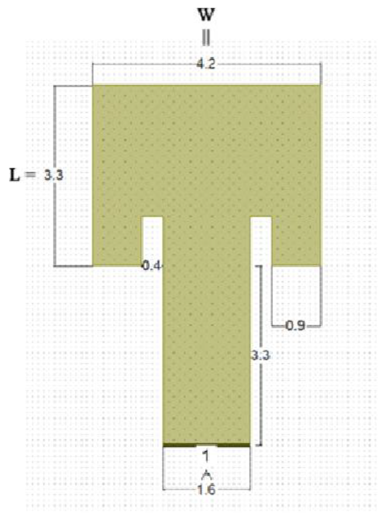
Figure 2.
Frequency dependence of S11 for the symmetric antenna.
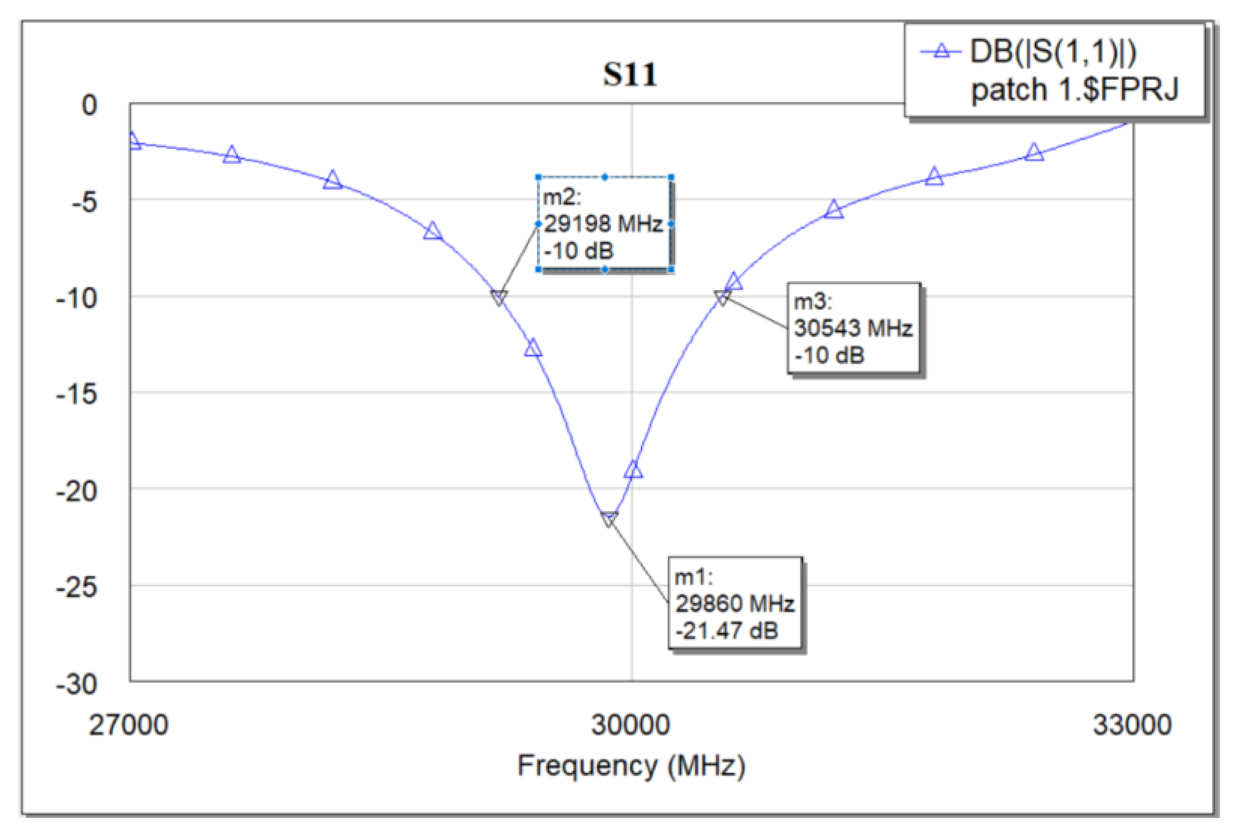
Figure 3.
Gain response of the proposed antenna.
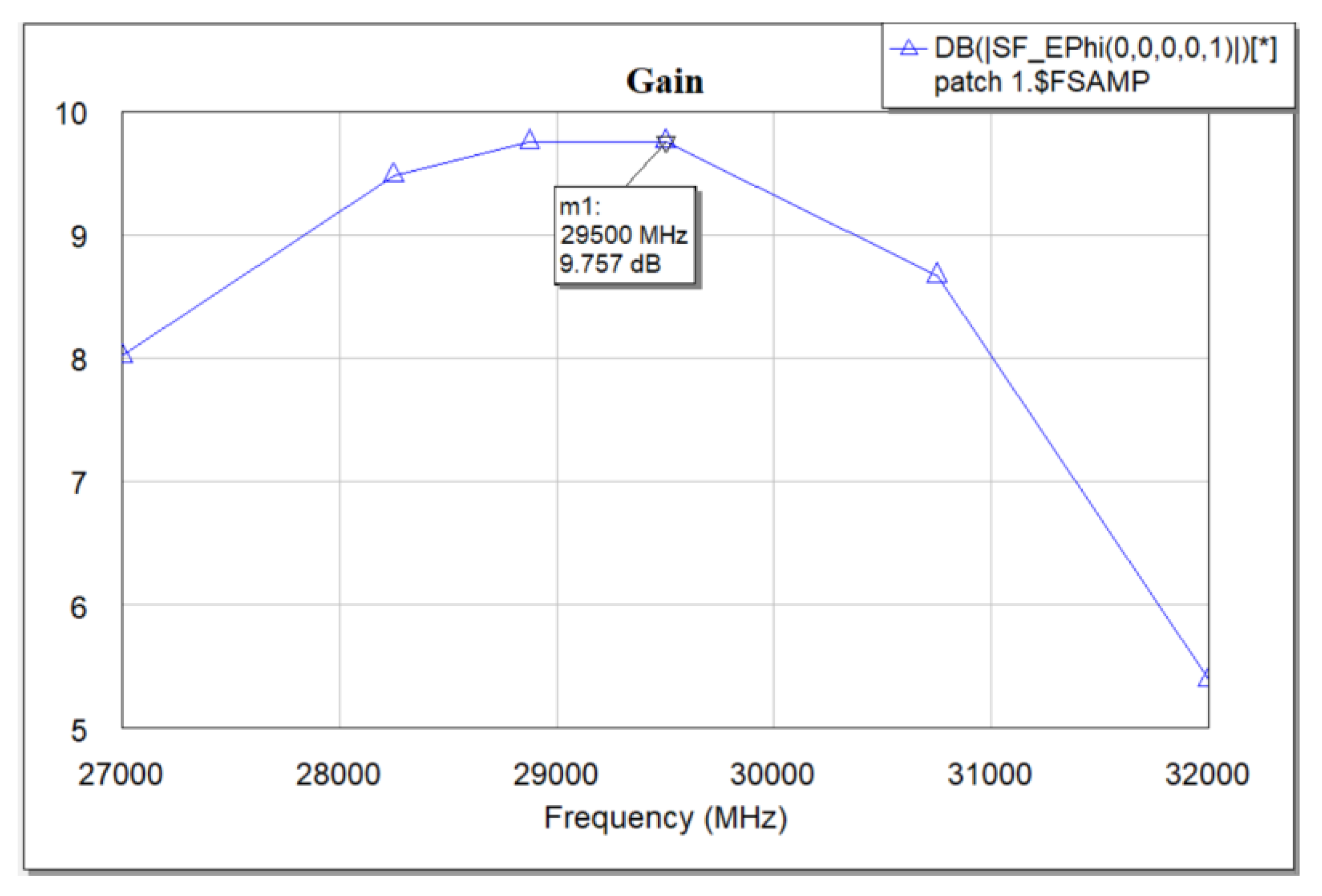
Figure 4.
(a) 3D antenna radiation pattern – plane view. (b) 3D antenna radiation pattern – side view.
Figure 4.
(a) 3D antenna radiation pattern – plane view. (b) 3D antenna radiation pattern – side view.
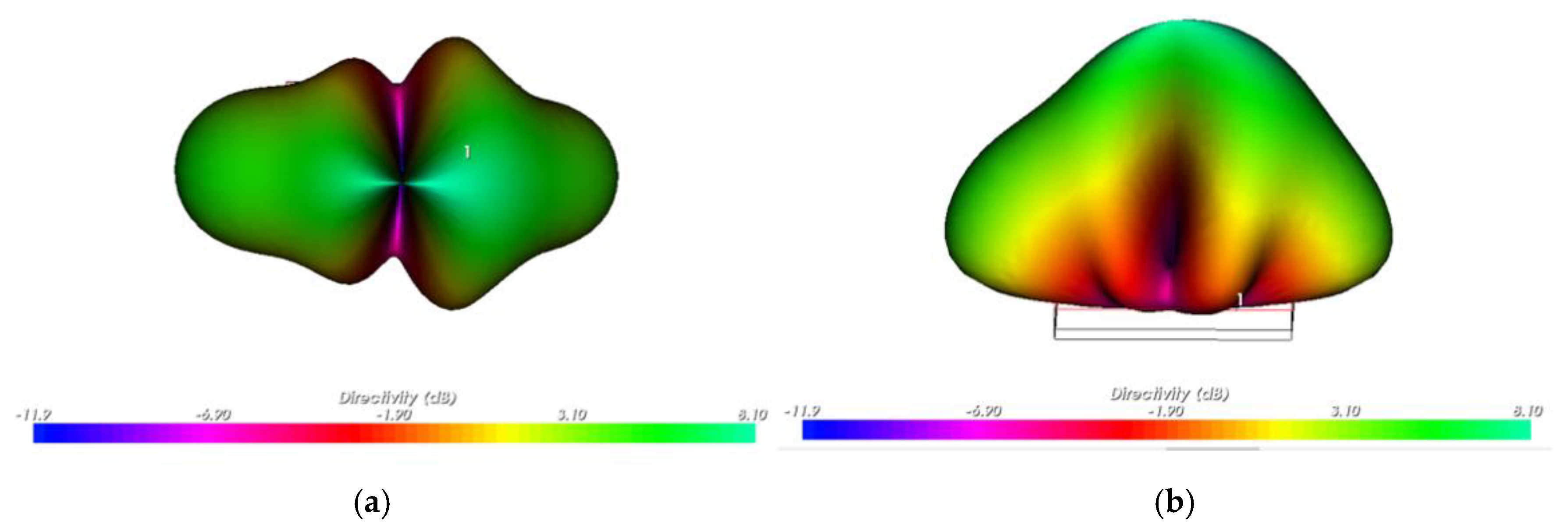
Figure 5.
(a) Antenna radiation pattern - E-plane. (b) Antenna radiation pattern - H-plane.
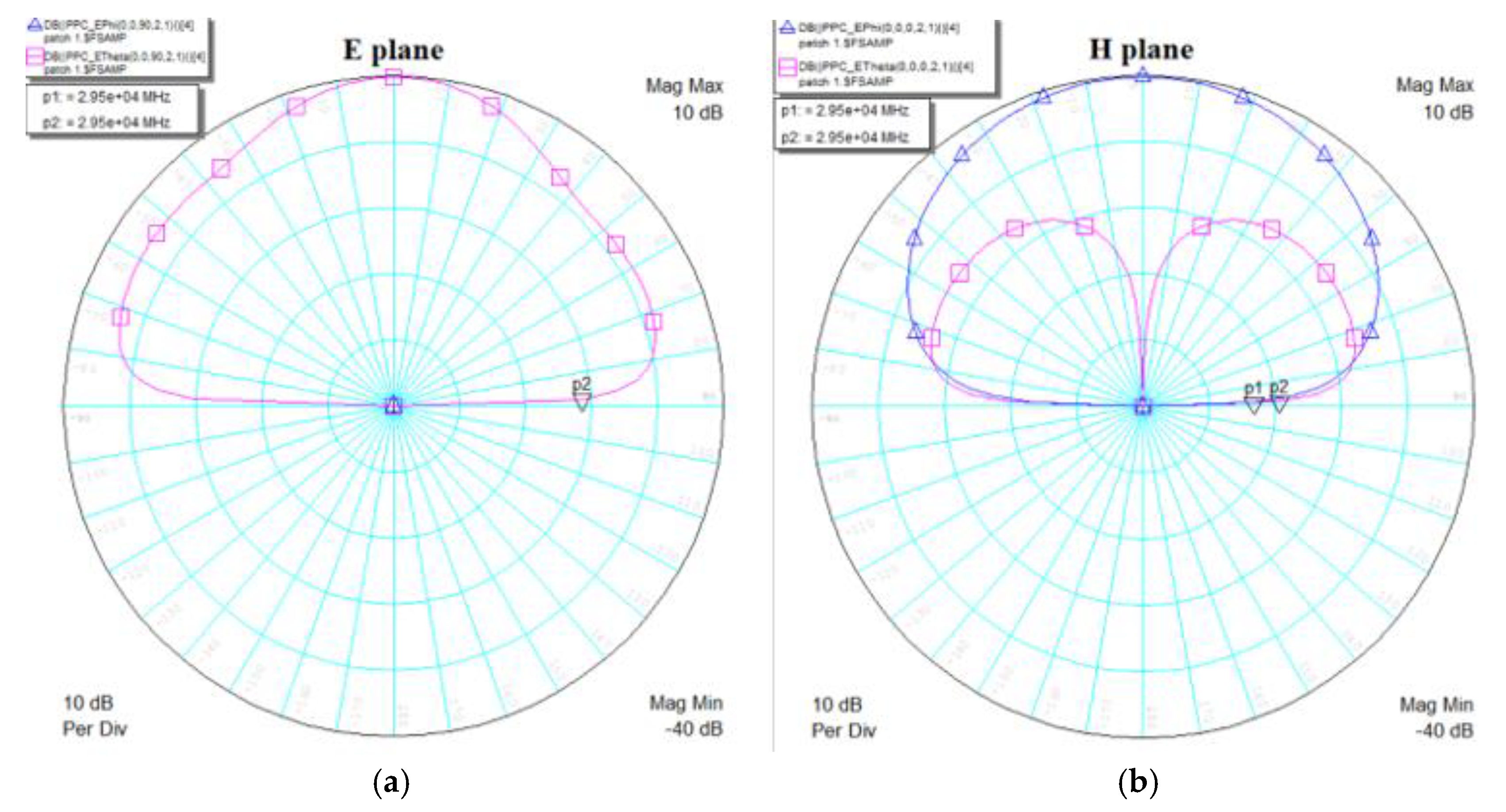
Figure 6.
First iteration.
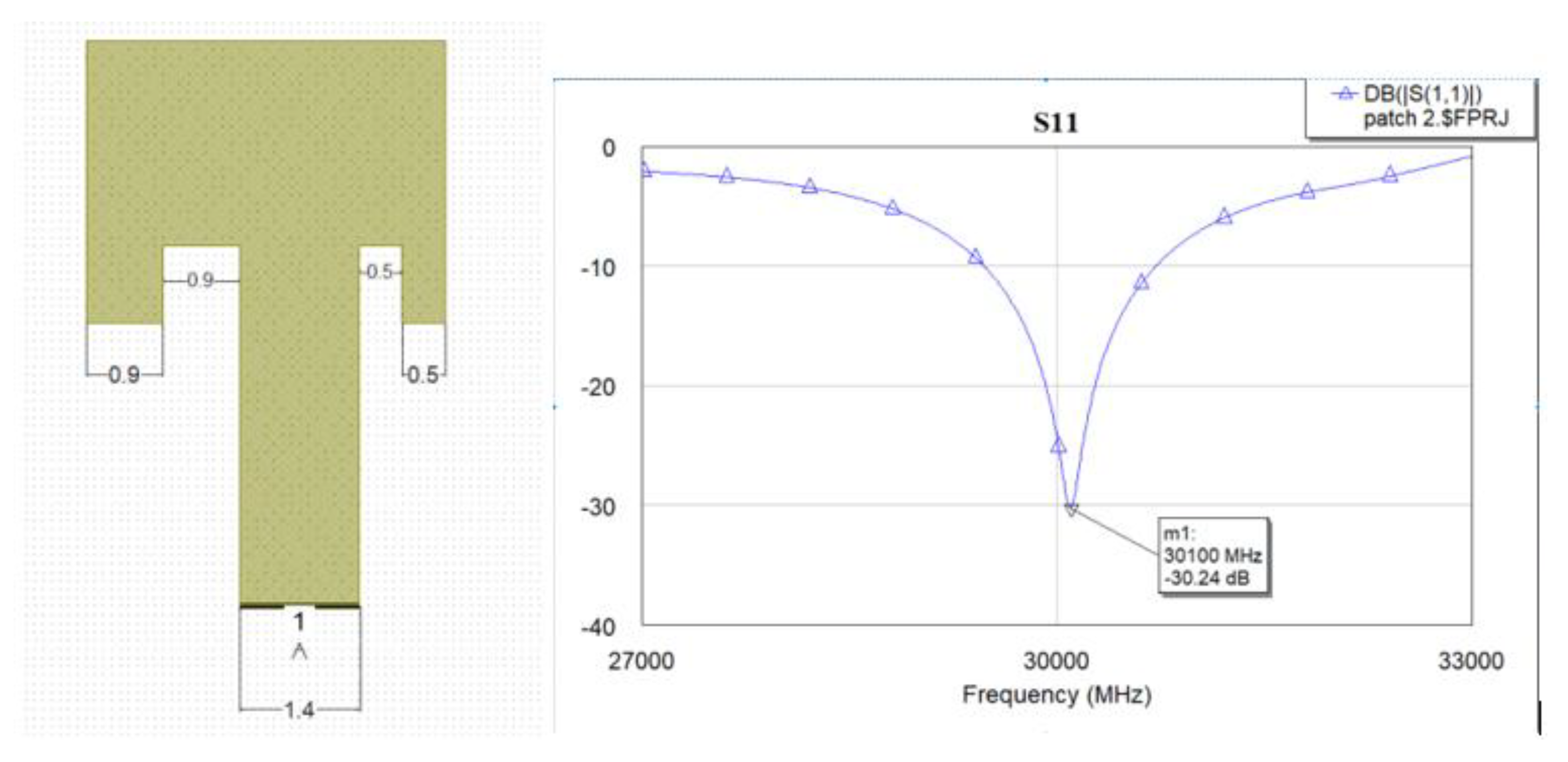
Figure 7.
Second iteration.
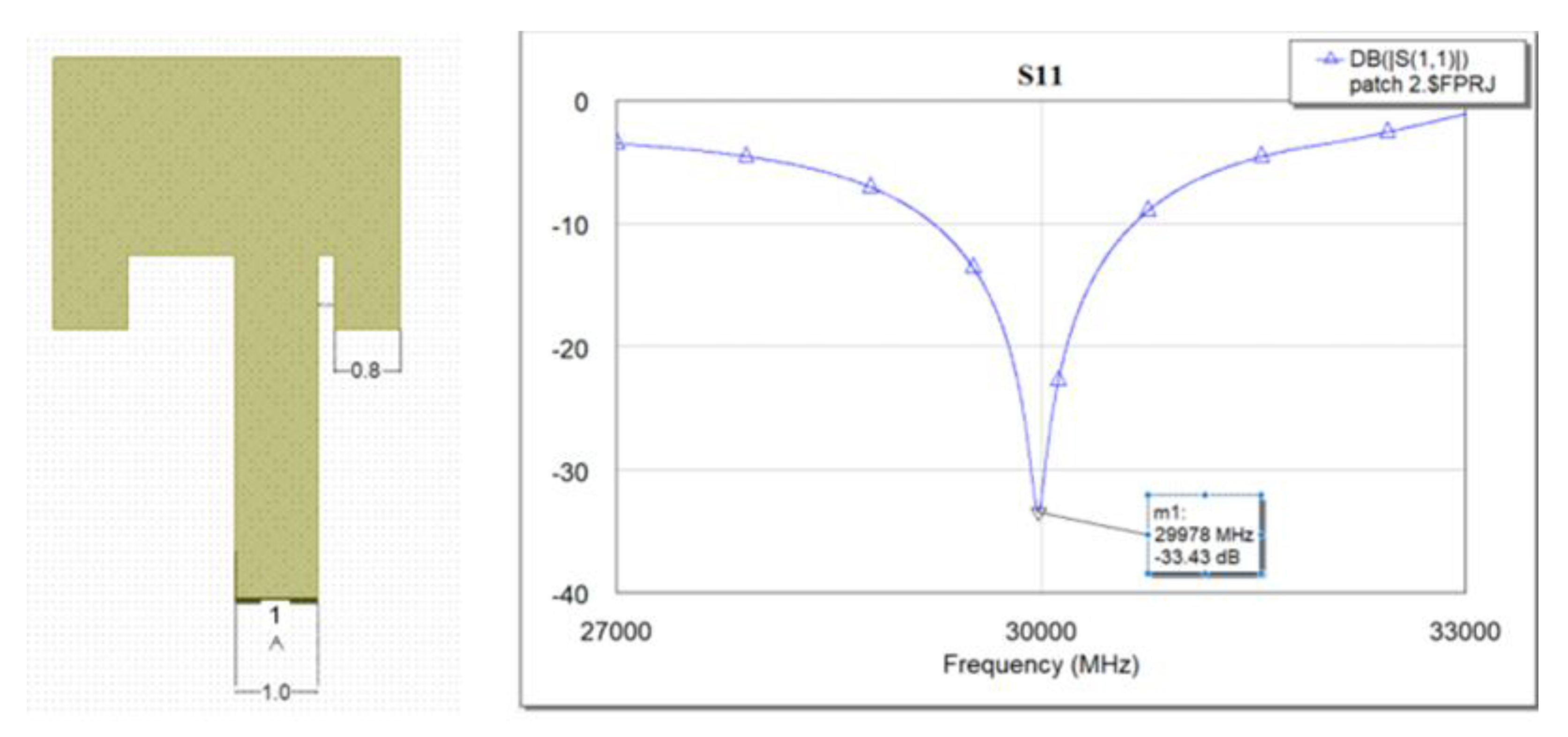
Figure 8.
Third iteration.
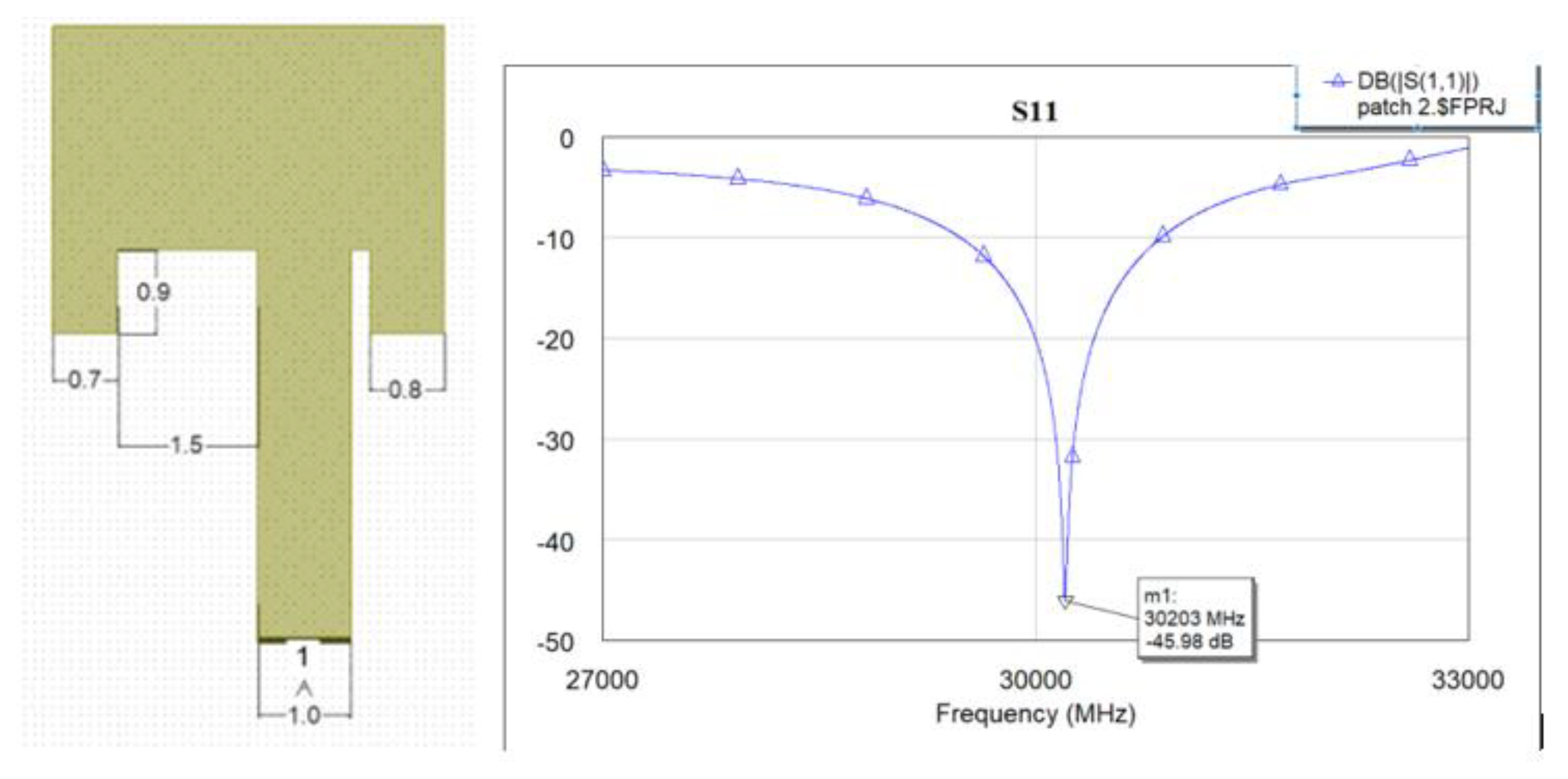
Figure 9.
Design of the proposed optimized antenna patch.
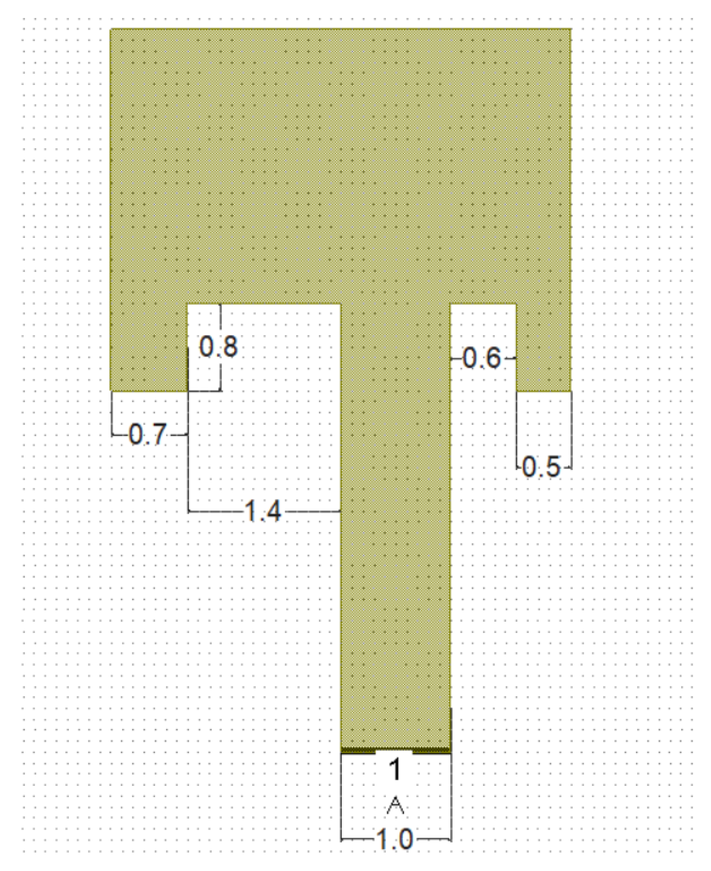
Figure 10.
S11 response for symmetrical antena and optimized antenna.
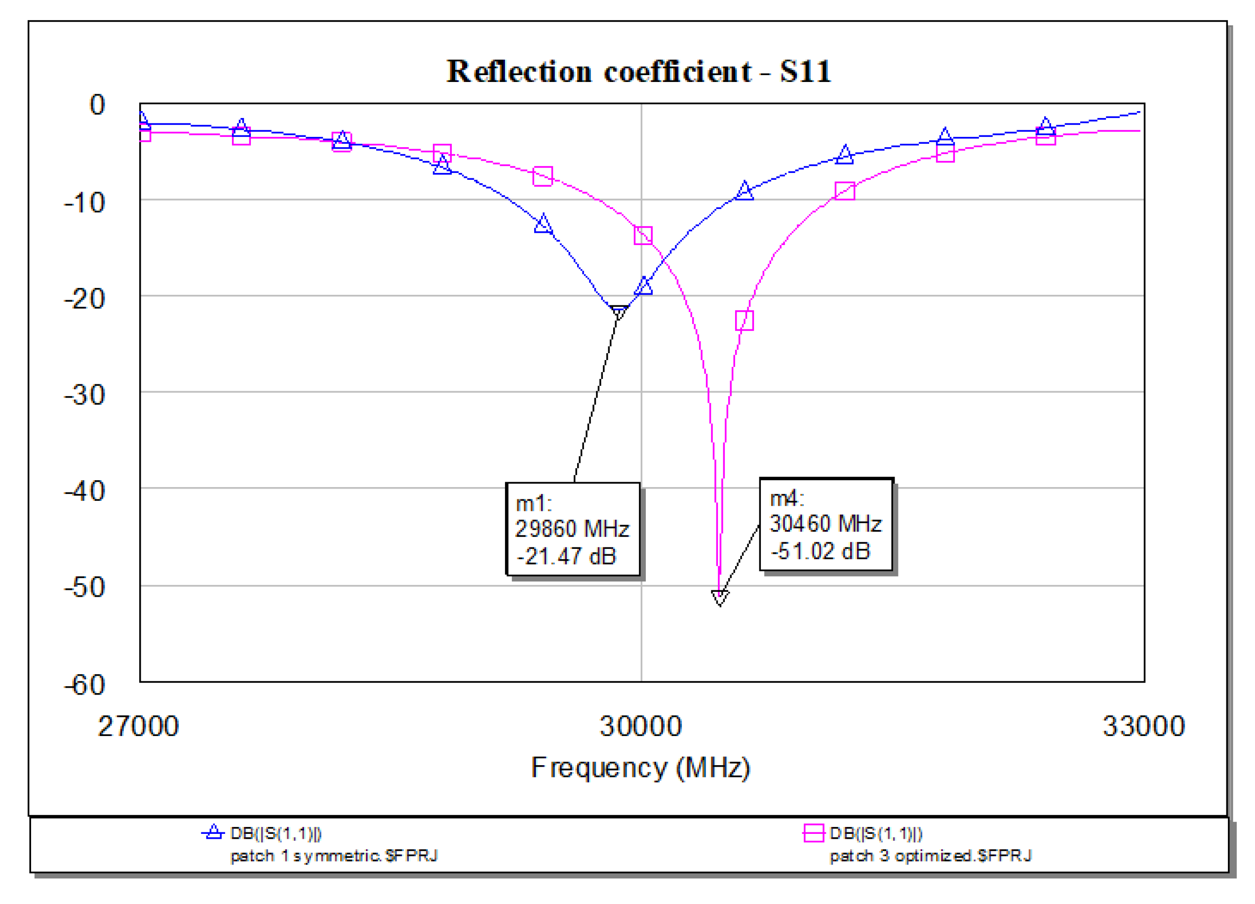
Figure 11.
Gain response for optimized antenna.
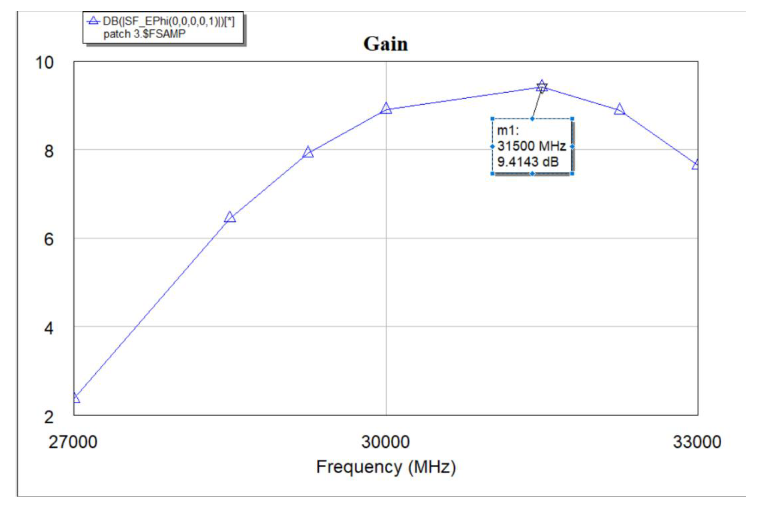
Figure 12.
(a) 3D optimized antenna radiation pattern – plane view. (b) Optimized antenna radiation pattern – side view.
Figure 12.
(a) 3D optimized antenna radiation pattern – plane view. (b) Optimized antenna radiation pattern – side view.
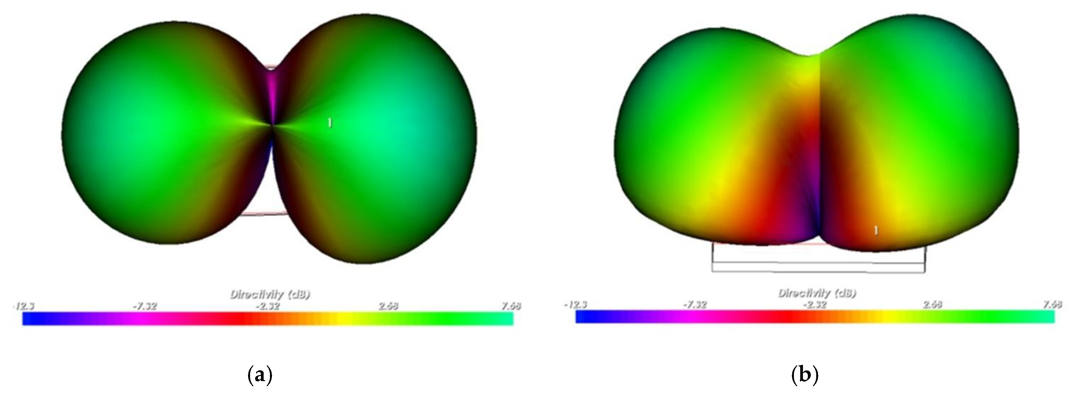
Figure 13.
(a) Optimized antenna radiation pattern - E-plane. (b) Optimized antenna radiation pattern - H-plane.
Figure 13.
(a) Optimized antenna radiation pattern - E-plane. (b) Optimized antenna radiation pattern - H-plane.
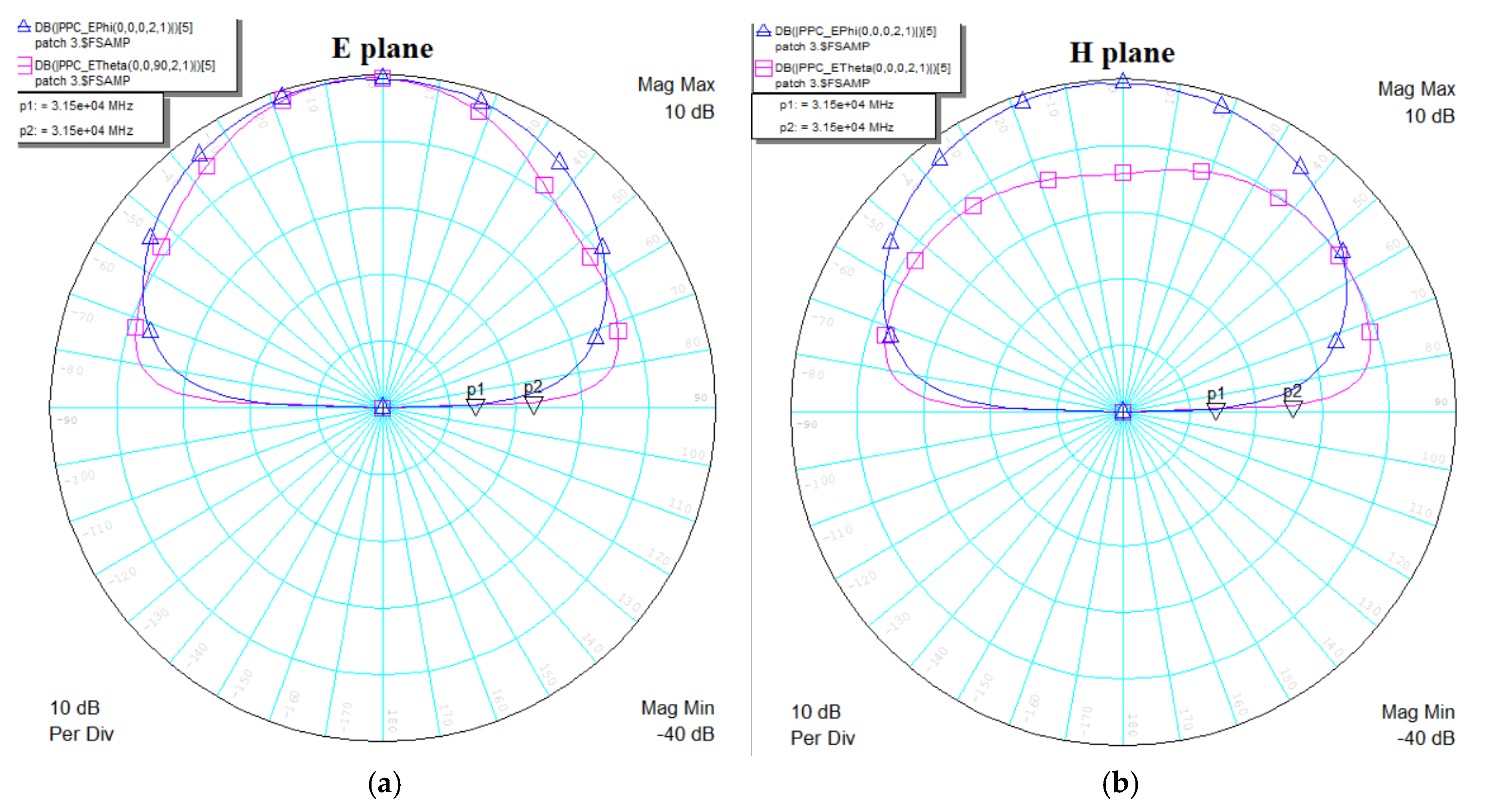
Figure 14.
Design of the proposed two-patch antenna system.
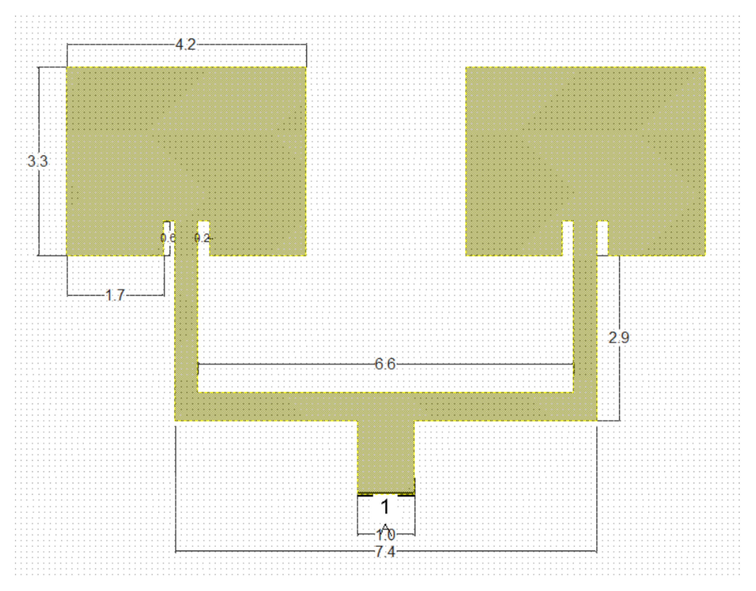
Figure 15.
S11 response for antenna system.
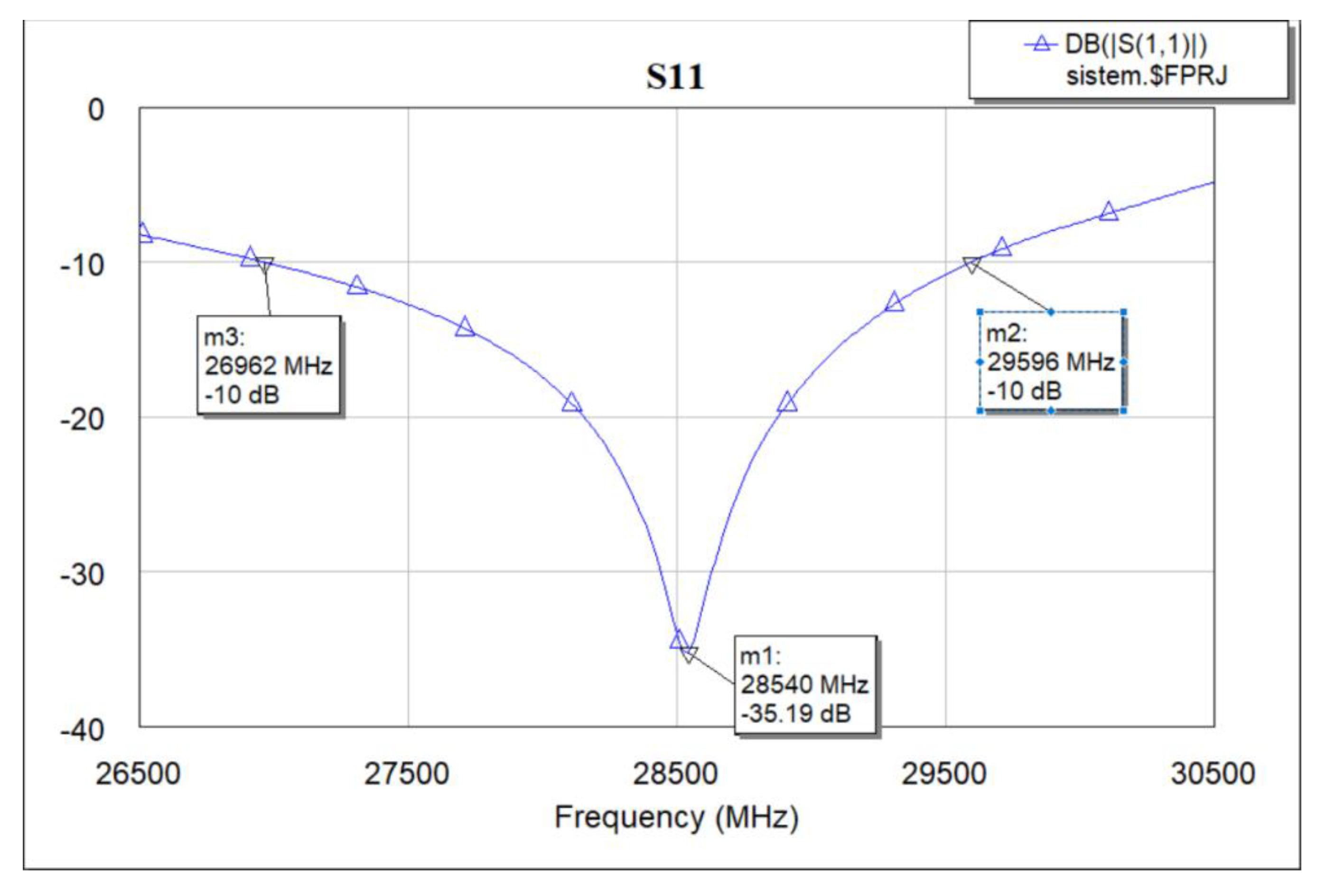
Figure 16.
Gain response for antenna system.
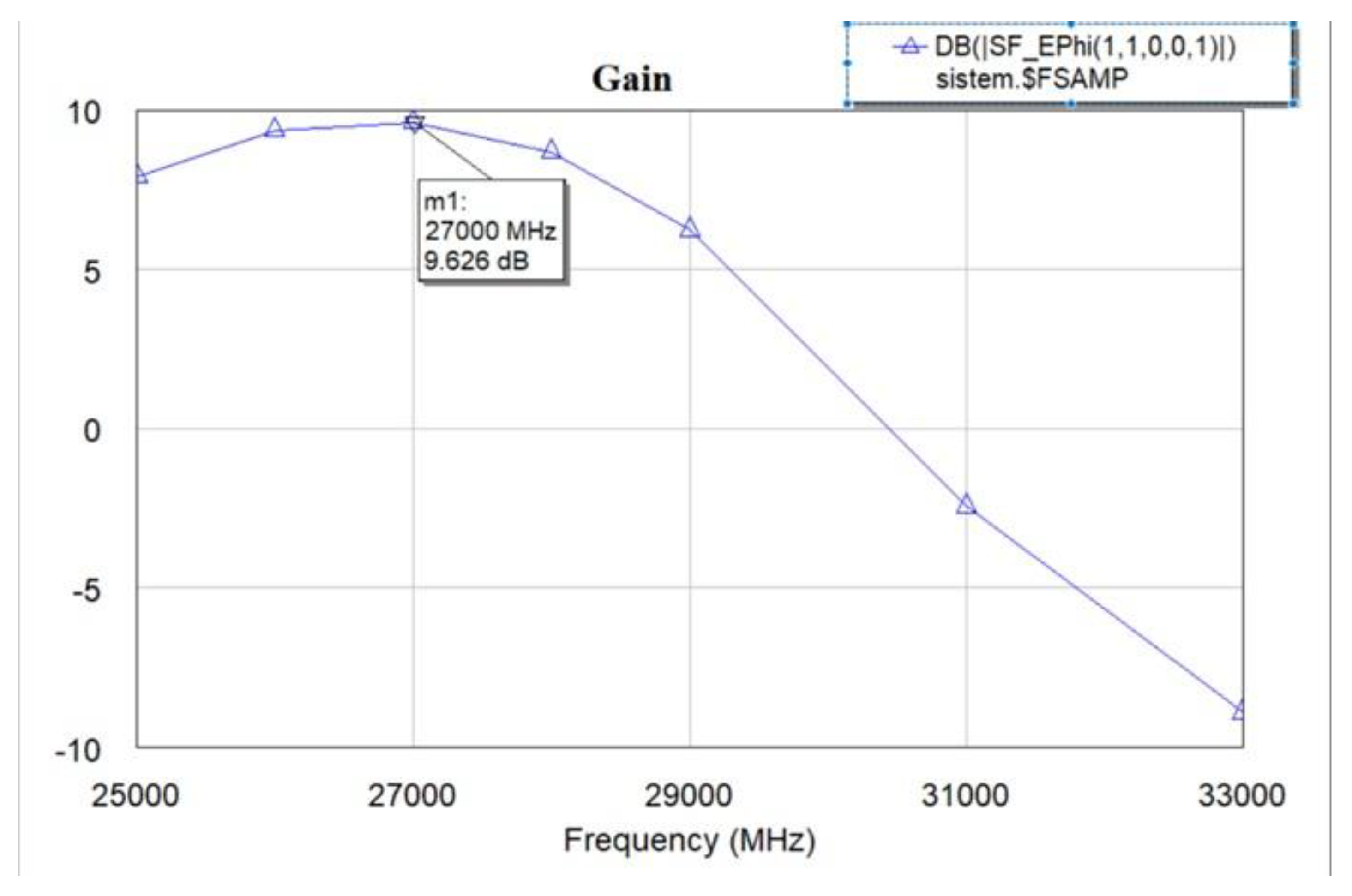
Figure 17.
(a) 3D antenna system radiation pattern - plane view. (b) 3D antenna system radiation pattern - side view.
Figure 17.
(a) 3D antenna system radiation pattern - plane view. (b) 3D antenna system radiation pattern - side view.
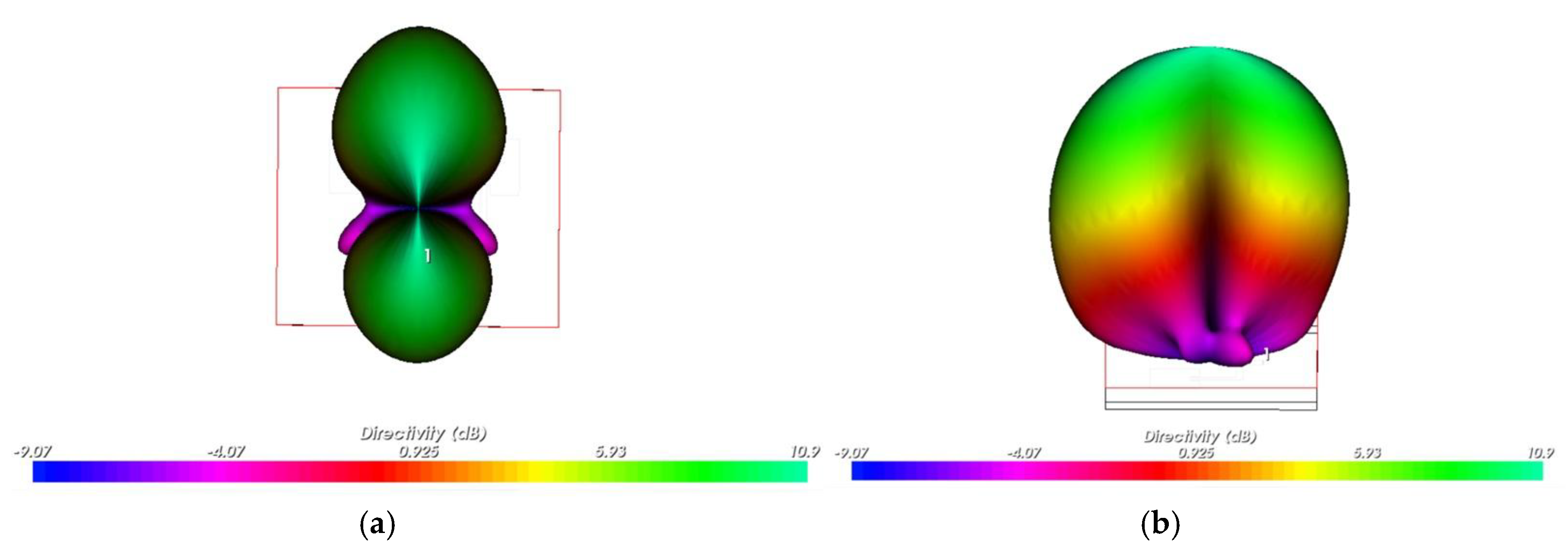
Figure 18.
(a) Antenna system radiation pattern - E-plane. (b) Antenna system radiation pattern - H-plane.
Figure 18.
(a) Antenna system radiation pattern - E-plane. (b) Antenna system radiation pattern - H-plane.
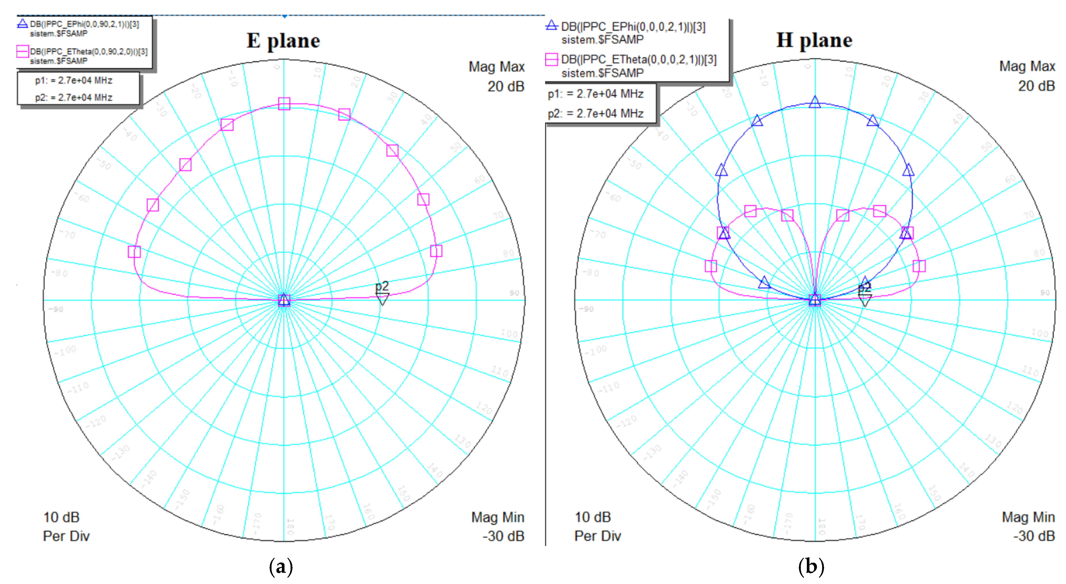

Table 1.
Performance parameters for the symmetric antenna, the optimized antenna and the antenna system.
Table 1.
Performance parameters for the symmetric antenna, the optimized antenna and the antenna system.
| S11 | Gain | Directivity | Bandwidth | VSWR | |
|---|---|---|---|---|---|
| Symmetric antenna | -21.47 dB | 9.757 dB | 8.10 dB | 1.5 GHz | 1.0977 |
| Optimized antenna | -51.02 dB | 9.414 dB | 7.68 dB | 1.4 GHz | 1.0399 |
| Antenna System | -35.19 dB | 9.626 dB | 10.9 dB | 2.6 GHz | 1.0585 |
Disclaimer/Publisher’s Note: The statements, opinions and data contained in all publications are solely those of the individual author(s) and contributor(s) and not of MDPI and/or the editor(s). MDPI and/or the editor(s) disclaim responsibility for any injury to people or property resulting from any ideas, methods, instructions or products referred to in the content. |
© 2025 by the authors. Licensee MDPI, Basel, Switzerland. This article is an open access article distributed under the terms and conditions of the Creative Commons Attribution (CC BY) license (http://creativecommons.org/licenses/by/4.0/).
Copyright: This open access article is published under a Creative Commons CC BY 4.0 license, which permit the free download, distribution, and reuse, provided that the author and preprint are cited in any reuse.


