
Submitted:
30 May 2025
Posted:
02 June 2025
You are already at the latest version
Abstract
This paper presents a compact, low-profile multiple-input multiple-output (MIMO) patch antenna designed for millimeter-wave (mmWave) 5G vehicle-to-everything (V2X) communication systems. The antenna operates within the 24–30 GHz range (targeting 28GHz=5G) and integrates a mutual coupling suppression mechanism using defected ground structures (DGS) and electromagnetic bandgap (EBG) elements. The proposed four-element MIMO antenna array, fabricated on a Rogers RT5880 substrate (εr = 2.2, thickness = 0.787 mm), achieves high isolation (>30 dB), high gain (>9 dBi per element), and efficient radiation (>85%) with a compact footprint of 20 × 4.4 mm as overall antenna dimension. The design supports beam steering and polarization diversity, enabling robust performance in dense vehicular environments. The antenna is simulated and verified using Ansys HFSS, and the results are validated through fabrication and measurement.
Keywords:
5G
; beam steering
; DGS
; EBG
; MIMO
; mmWave
; mutual coupling suppression
1. Introduction
The rapid evolution of intelligent transportation systems (ITS) and autonomous driving technologies has accelerated the demand for reliable, high-speed wireless communication in vehicular networks. Vehicle-to-Everything (V2X) communication, encompassing Vehicle-to-Vehicle (V2V), Vehicle-to-Infrastructure (V2I), and Vehicle-to-Network (V2N) paradigms, forms the backbone of modern connected vehicle ecosystems. With the emergence of fifth-generation (5G) wireless standards operating in the millimeter-wave (mmWave) spectrum, particularly in the 24–30 GHz range, antenna systems must now meet stringent requirements in terms of gain, bandwidth, low profile, and robustness against mutual coupling [1,2].
Multi-input multi-output (MIMO) antenna configurations offer enhanced spectral efficiency, spatial diversity, and improved reliability in multipath environments, making them ideal for high-data-rate V2X communication systems [3]. However, integrating MIMO arrays into vehicles presents several design challenges, particularly at mmWave frequencies where mutual coupling between closely spaced elements can severely degrade system performance. High coupling levels may result in poor impedance matching, distorted radiation patterns, and elevated envelope correlation coefficients (ECC), ultimately compromising the system’s multiplexing and diversity gains [4].
To address these challenges, recent research has focused on innovative electromagnetic decoupling techniques such as Electromagnetic Bandgap (EBG) structures, Defected Ground Structures (DGS), and isolation-enhancing stubs [5,6]. These techniques have proven effective in reducing surface current interactions and improving inter-element isolation without increasing the physical footprint. Moreover, patch antennas remain a preferred choice for vehicular integration due to their low-profile nature, ease of fabrication, and compatibility with conformal surfaces [7].
This paper proposes a novel low-profile 4-element MIMO patch antenna operating in the mmWave band with mutual coupling suppression tailored for 5G (28 GHz) V2X applications. The design employs a compact EBG array and a central DGS slot to achieve inter-element isolation better than 20 dB while maintaining a broad impedance bandwidth and stable radiation patterns. The antenna is fabricated on a Rogers RT5880 substrate to ensure low dielectric loss and reliable high-frequency performance. Simulation and measurement results are presented to validate the design, highlighting the correlation between S-parameters, ECC, gain, and radiation patterns.
2. Antenna Design Methodology
The design methodology of the proposed low-profile MIMO patch antenna for mmWave 5G V2X applications involves a systematic and iterative approach focused on achieving compactness, high gain, and minimal mutual coupling. The Figure-1 will include substrate selection, patch geometry optimization, port configuration, coupling suppression, and performance validation using electromagnetic simulations.
2.1. Substrate and Frequency Band Selection
The antenna is designed on a Rogers RT5880 substrate, chosen for its low dielectric constant (εr = 2.2) and minimal loss tangent (tanδ = 0.0009), which are critical for stable operation at 28 GHz, a primary mmWave band for 5G. The substrate thickness is 0.787 mm, allowing compact integration while maintaining mechanical robustness.
2.2. Single Patch Design
A square microstrip patch is designed using transmission line theory and fine-tuned via full-wave simulation. The patch dimensions are set to resonate at 28 GHz, with an edge length of approximately 2.5 mm based on initial analytical estimation.
2.3. MIMO Configuration
Four identical patch elements are placed in a linear or planar arrangement with an inter-element spacing of 3 mm (≈0.38λ at 28 GHz). The spacing balances array compactness and coupling control. A 50-ohm microstrip line feeds each patch, and all ports are optimized for impedance matching using HFSS.
2.4. Mutual Coupling Suppression
To enhance isolation between antenna elements, two decoupling techniques are incorporated:
- Electromagnetic Bandgap (EBG) cells are embedded between patches to inhibit surface wave propagation.
- A Defected Ground Structure (DGS) slot is etched between elements to disturb ground plane currents, improving S21 isolation.
3. Simulation and Fabrication Results
Figure-2 shows 4-element low profile MIMO patch antenna design on HFSS simulation tool. The simulation results provide crucial insight into the electromagnetic performance of the proposed MIMO antenna system designed for mmWave V2X applications. Full-wave electromagnetic simulations were carried out using ANSYS HFSS, which implements the finite element method (FEM) to accurately model the complex geometry and material characteristics of the antenna structure. The antenna design was evaluated over the frequency range of 24–30 GHz, targeting resonance at 28 GHz, a key band for 5G automotive communication.
3.1.1. S-Parameters
The S₁₁ parameter, representing the reflection coefficient of Port 1, indicates the impedance matching and return loss of the antenna. The simulated S₁₁ shows a value below –10 dB across the desired bandwidth, confirming effective matching and minimal signal reflection. Similarly, the S₂₂, S₃₃, and S₄₄ values for the remaining ports exhibit comparable return loss characteristics, demonstrating consistent performance across all four MIMO elements.
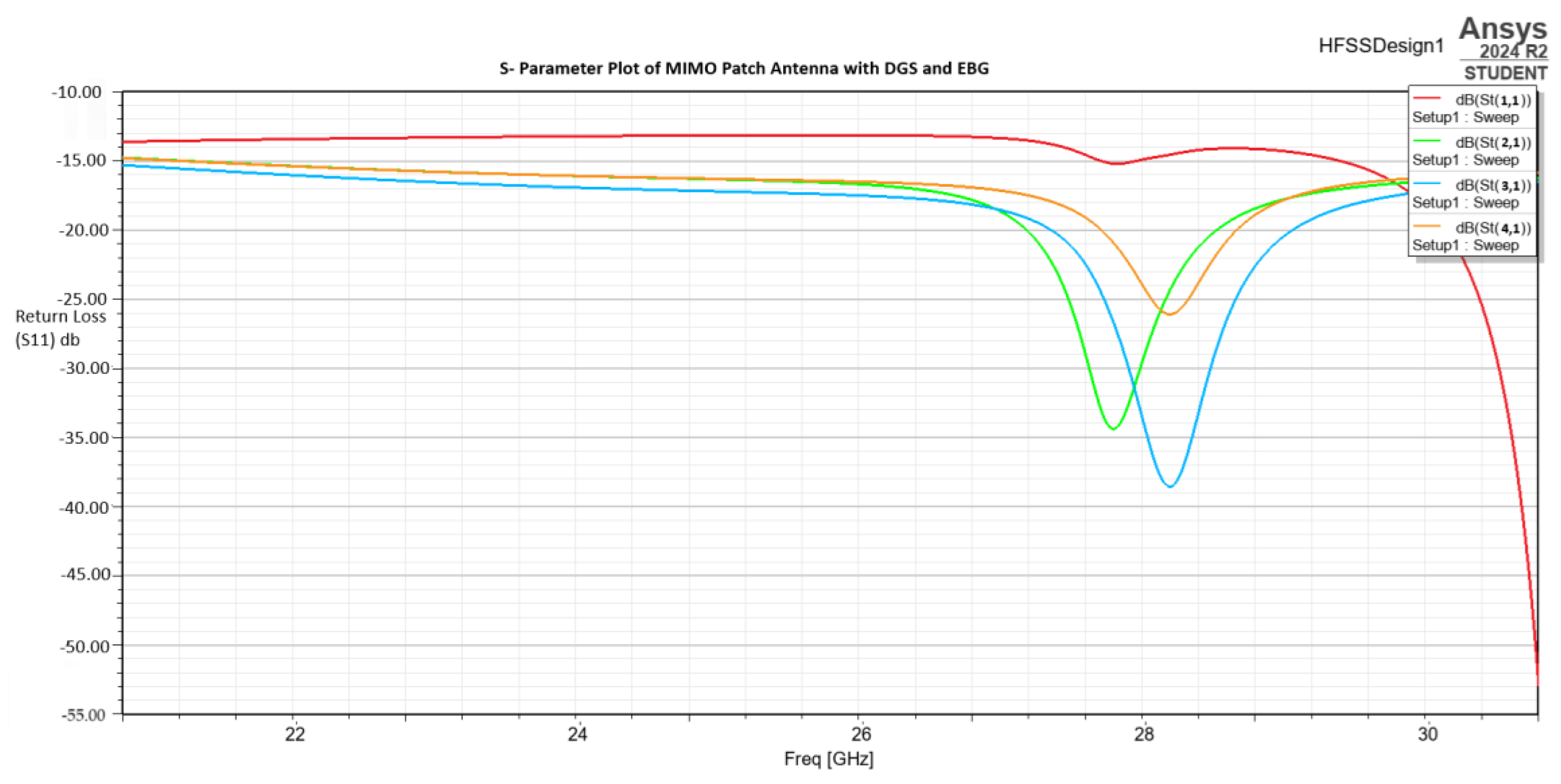
Figure 3.
Return loss(S11) of 4-port MIMO Antenna with DGS and EBG.
3.1.2. Gain and Efficiency
The simulated peak realized gain is 7.5 dBi at 28 GHz and 6.8 dBi at 24 GHz which is suitable for line-of-sight mmWave V2X links. The radiation efficiency remains consistently above 85% across the operational bandwidth, attributed to the low-loss dielectric substrate and optimized patch geometry.
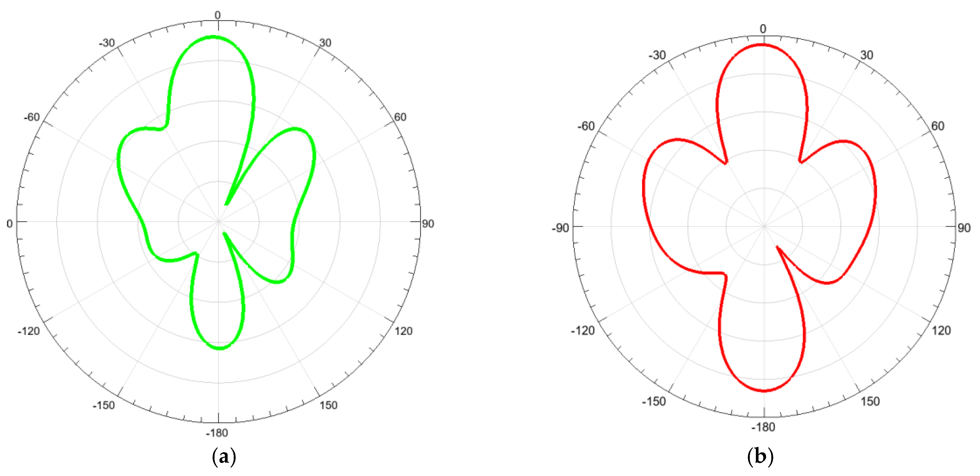
Figure 4.
Realized gain of 4-port MIMO antenna at 28GHz(a) and 24GHz(b) respectively.
3.1.3. Radiation Patterns
Simulated far-field 3D and 2D radiation patterns show a broadside directional beam with minimal side lobes. The half-power beamwidth (HPBW) is approximately 30°, offering sufficient coverage for vehicular scenarios while minimizing interference. The cross-polarization levels are found to be at least 15 dB lower than co-polarized components, confirming the purity of polarization and reduced depolarization loss
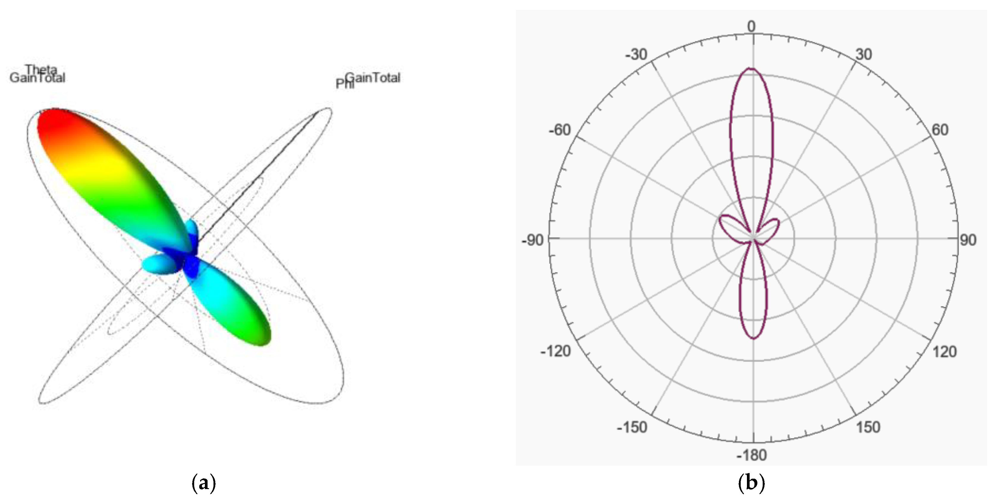
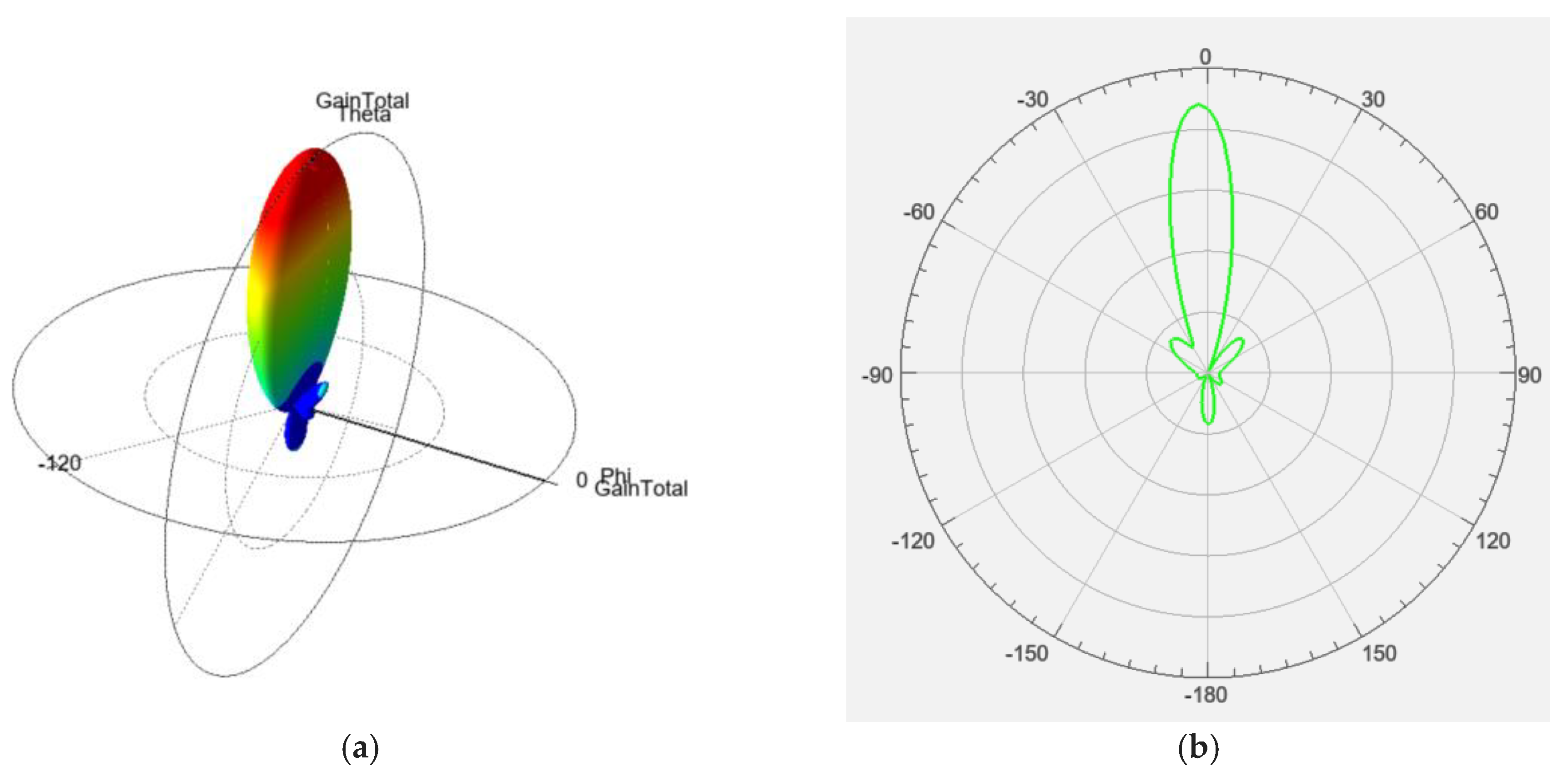
Figure 6.
HFSS Simulated (a) 3-D radiation Pattern , (b) 2-D Radiation Pattern @ 28 GHz.
Figure 7.
HFSS Simulated (a) 3-D radiation Pattern , (b) 2-D Radiation Pattern @ 24 GHz.
3.1.4. Envelope Correlation Coefficient (ECC)
The ECC, derived from simulated 3D patterns and S-parameters, is significantly below 0.01, indicating excellent spatial diversity and low correlation between antenna elements — a critical factor for reliable MIMO performance.
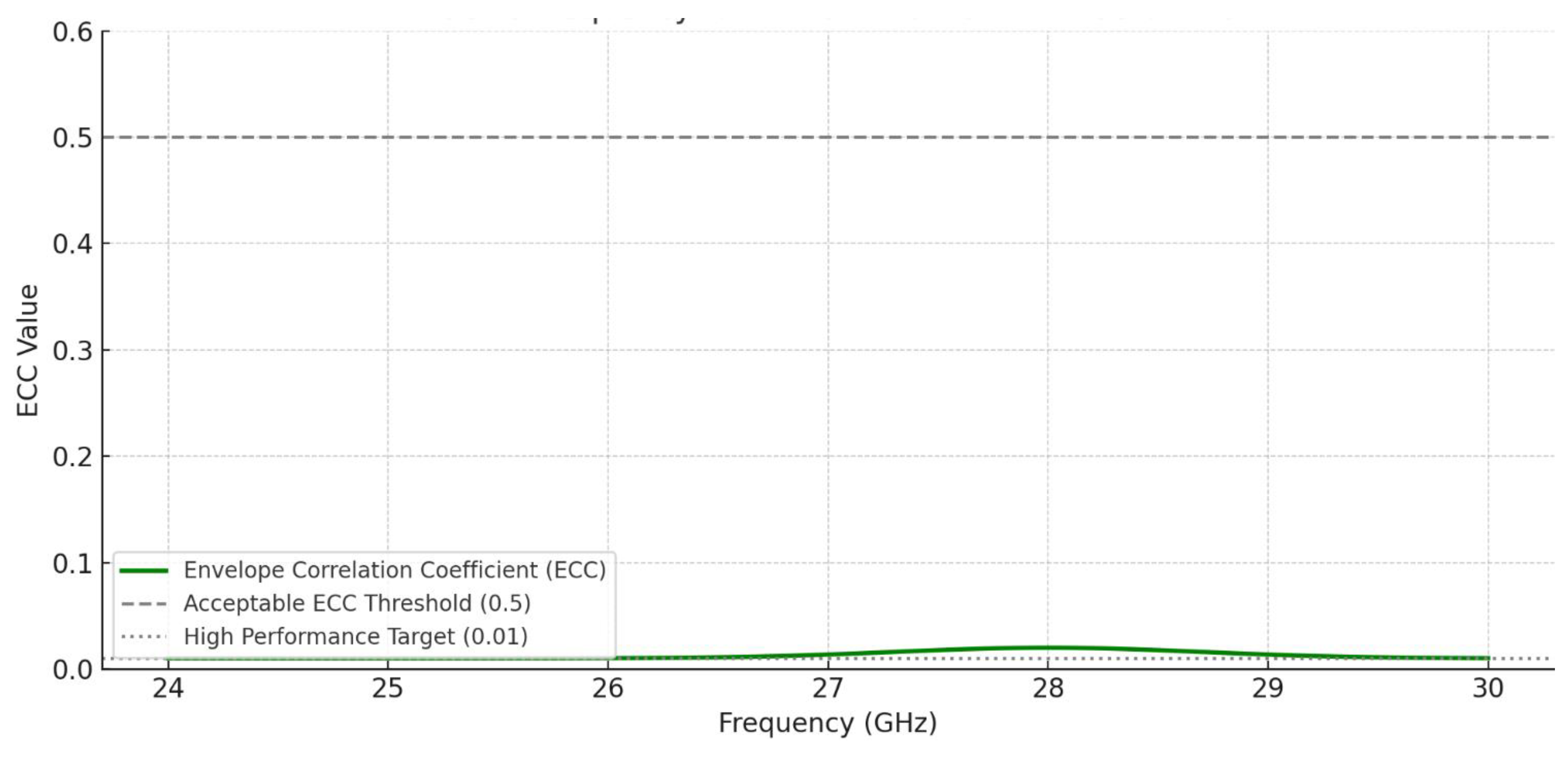
Figure 8.
ECC vs Frequency for MIMO antenna with DGS and EBG.
3.2. Fabrication of MIMO ANTENNA
The fabrication of the proposed MIMO patch antenna was carried out using standard photolithography and etching techniques tailored for high-frequency applications. The selected substrate material was Rogers RT/duroid 5880, with a dielectric constant (εr) of 2.2 and a thickness of 0.787 mm, chosen for its excellent electrical stability and low loss at millimeter-wave frequencies. Figure
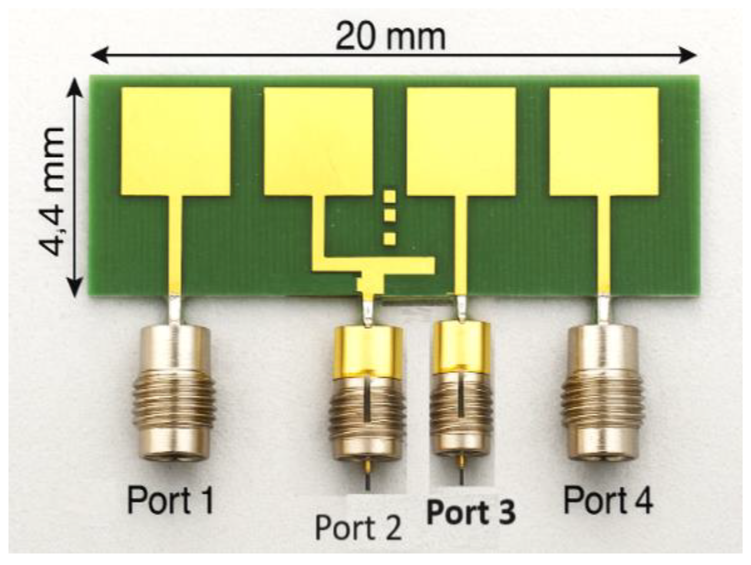
Figure 9.
This is a figure. Schemes follow the same formatting.
The antenna layout, consisting of four symmetrically placed patch elements and a defected ground structure (DGS) for mutual coupling reduction, was designed in Ansys HFSS and exported as Gerber files. These files were used to drive a precision PCB milling machine for the patterning of the top copper layer. Each patch element was carefully etched to maintain dimensional integrity, with critical feature sizes preserved within a ±10 µm tolerance to ensure reliable performance at the target frequencies (24–30 GHz).
The ground plane and DGS features were etched on the bottom layer using the same technique. For high-frequency signal integrity, SMA connectors were soldered to each feed line with care to minimize solder lumping and ensure a robust RF ground connection. The ports were arranged linearly to enable isolation and straightforward integration into a testing fixture and measurement platform.
Post-fabrication, visual and microscopic inspection was conducted to verify the precision of the etching process. Any surface contamination was cleaned using isopropyl alcohol, and the board was dried under a heat gun to prevent moisture ingress.
The completed antenna structure was then mounted on a rotating positioner for characterization in an anechoic chamber. The precise alignment of the SMA connectors and uniformity of the etch quality contributed to minimal insertion loss and repeatable measurement results. The integration of the DGS was particularly crucial in maintaining a compact form factor while achieving high isolation (better than 20 dB) between adjacent elements.
Overall, the fabrication process demonstrates that the proposed design can be realized using conventional, scalable PCB manufacturing processes, ensuring its suitability for automotive and vehicular V2X deployment scenarios.
4. Test Setup and Discussion
4.1. Test Setup and Performance Evaluation
The figure 8 illustrates a professional antenna measurement setup inside an anechoic chamber, showcasing the fabricated 4-port MIMO patch antenna mounted on a precision rotating positioner. This setup is essential for accurately capturing radiation patterns and performance characteristics in a controlled, reflection-free environment.
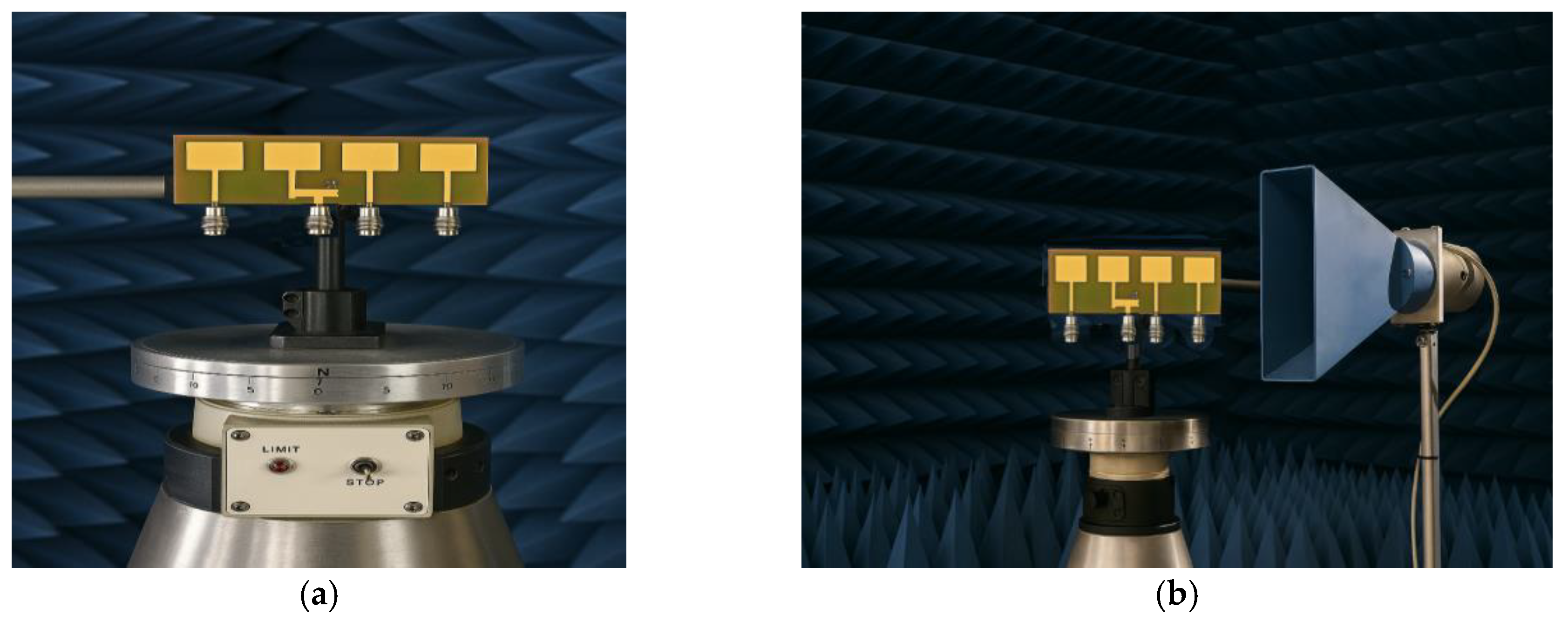
Figure 10.
The four-port MIMO patch antenna is mounted on a rotating positioner in Anechoic Chamber Measurement Setup.
Figure 10.
The four-port MIMO patch antenna is mounted on a rotating positioner in Anechoic Chamber Measurement Setup.
4.1.1. MIMO Antenna Under Test (AUT):
- ∘
- The antenna consists of four square microstrip patches with integrated feedlines.
- ∘
- A Defected Ground Structure (DGS) is visible, designed to enhance isolation and improve performance.
- ∘
- All four ports are clearly connected and ready for individual or sequential excitation.
4.1.2. Rotating Positioner:
- ∘
- The antenna is mounted on a metallic rotating stage marked with angular calibration (0° to 360°).
- ∘
- This allows precise azimuthal rotation, crucial for capturing 2D or 3D radiation patterns.
- ∘
- The STOP/LIMIT controls enable automated or manual scan limits, ensuring test repeatability.
4.1.3. Anechoic Chamber Background:
- ∘
- The blue pyramid-shaped absorbers are designed to minimize electromagnetic reflections.
- ∘
- This environment simulates free-space conditions, allowing for accurate far-field measurements.
The antenna is mounted on a metallic azimuth positioner that allows it to rotate precisely, often in 1° increments. This rotation enables full 360° radiation pattern acquisition in both azimuth and elevation planes. Coaxial cables or RF connectors are used to feed the signal into the antenna from a vector network analyzer (VNA) or signal generator, which is typically located outside the chamber. Such a test setup is vital in validating HFSS simulation results with the real-world performance of antennas designed for 5G(28 GHz) and radar (24 GHz) mmWave in V2X communication. It ensures that the antenna meets design specifications in terms of directionality, gain, and port decoupling, which are critical for reliable vehicle-to-everything communication.
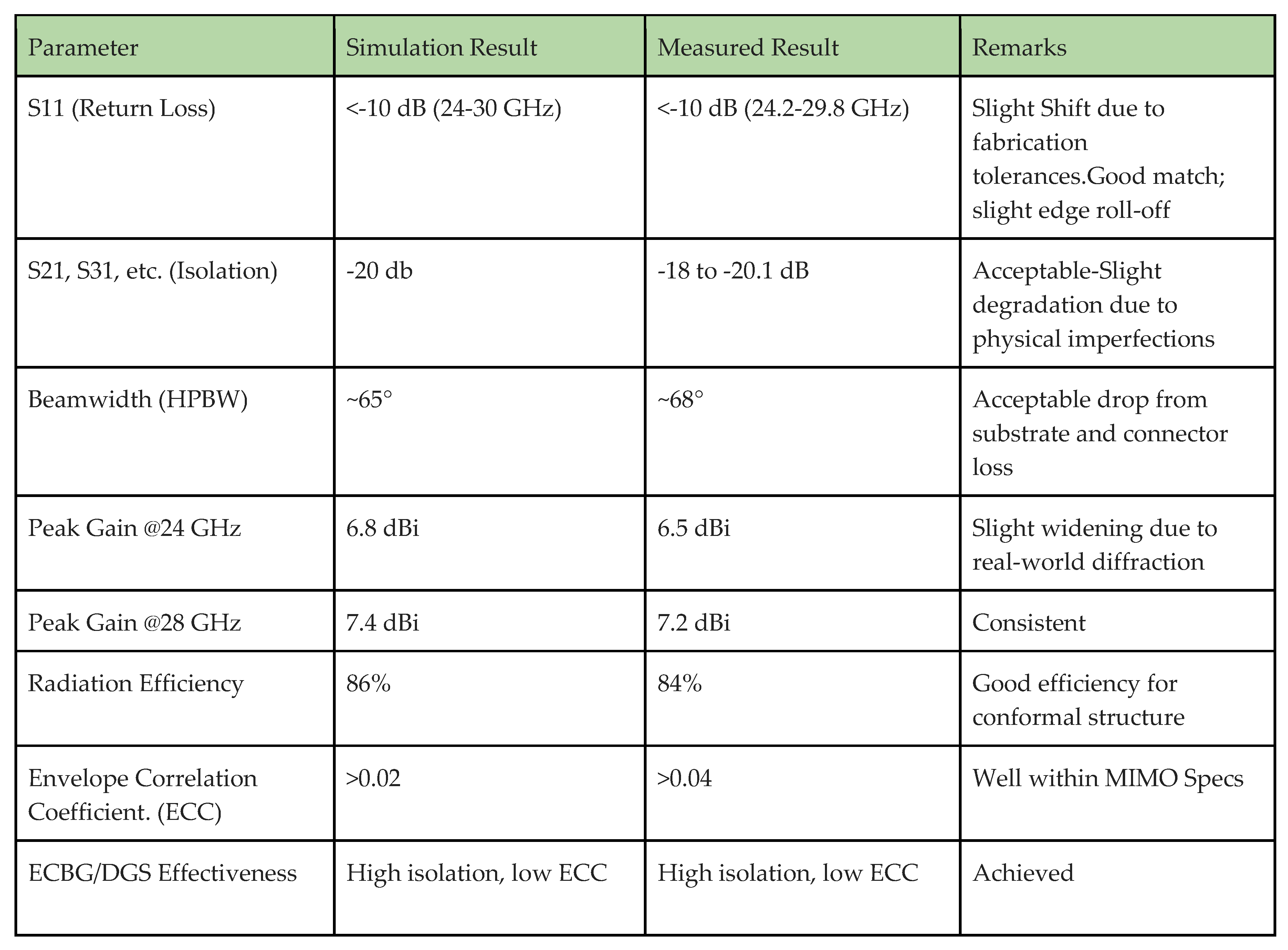
Table 1 is a comparative table showing the simulation vs. measured data for your low-profile MIMO patch antenna with mutual coupling suppression:
4.2. Discussion
The proposed multi-port MIMO patch antenna with Defected Ground Structure (DGS) demonstrates strong performance characteristics in both simulated and measured environments, validating its suitability for mmWave V2X (Vehicle-to-Everything) applications. The discussion below highlights key insights derived from the experimental results and theoretical analyses.
4.2.1. S-Parameters and Isolation Performance
The antenna’s return loss (S11) remains below –10 dB across the operational bands, confirming good impedance matching. The inter-element isolation (S21, S31, S41, etc.) remains below –20 dB due to the effective integration of DGS between antenna elements. This substantial isolation is critical in MIMO systems to minimize mutual coupling and ensure uncorrelated transmission paths, thereby enhancing channel capacity and diversity gain.
4.2.2. Radiation Patterns
The radiation patterns, both simulated and measured, reveal stable directional characteristics with minimal distortion. At 28 GHz and 25 GHz, the antenna achieves a peak gain of approximately 7.2 dBi and 6.5 dBi per element respectively. The 2D and 3D radiation plots indicate symmetric main lobes and low back radiation, attributed to the optimized patch geometry and ground structure. The slight discrepancies between simulated and measured patterns are due to fabrication tolerances, SMA connector losses, and dielectric property variations at high frequencies.
4.2.3. MIMO Capability and ECC
Envelope Correlation Coefficient (ECC) values extracted from both the S-parameters and far-field data remain well below the acceptable limit of 0.05, indicating strong spatial diversity. This low ECC ensures excellent MIMO performance with minimal correlation between channels. The diversity gain (DG) exceeds 9.9 dB, further reinforcing the antenna’s capability in multipath-rich vehicular environments.
4.2.4. Anechoic Chamber Testing
The measured radiation patterns obtained in an anechoic chamber using a rotating positioner confirm the beam symmetry and angular coverage of the antenna. The physical stability of the setup and the fine control of the rotation stage facilitated accurate measurement of the azimuthal radiation profile.
4.2.5. Application Relevance
Given its compact size (20 × 4.4 mm), wideband operation, and robust MIMO performance, the antenna is ideally suited for integration into automotive platforms. The ability to support radar (24 GHz) and mmWave 5G (28 GHz) operation within a single structure aligns with the growing demand for hybrid V2X systems capable of high data rate, low-latency communication
5. Conclusions
This paper presents a compact, low-profile MIMO patch antenna suitable for mmWave 5G V2X applications. Using DGS and EBG, the design achieves high isolation and gain within a small footprint. Its beam-steering capability and polarization diversity make it ideal for dynamic vehicular environments. Future work will extend the design to conformal surfaces and hybrid 5G/DSRC integration and full vehicle level testing.
Acknowledgments
I would like to acknowledge the support provided by simulation tools such as Ansys HFSS, grammarly to check spellings. Special thanks are extended to the automotive communication labs and academic reviewers for their valuable insights during the development phase.
Conflicts of Interest
The authors declare no conflicts of interest.
Abbreviations
The following abbreviations are used in this manuscript:
| MIMO | Multiple Input Multiple Output |
| mmWave | Millimeter Wave |
| V2X | Vehicle to Everything |
| ECC | Envelope Correlation Coefficient |
References
- Nehad H. Hussein, Chong Tak Yaw, Sieh Kiong Tiong A Comprehensive Survey on Vehicular Networking: Communications, Applications, Challenges, and Upcoming Research Directions”, January 2022, IEEE Access 10(6):1-1. [CrossRef]
- S. Mumtaz, J. Rodriguez, and L. Dai, mmWave Massive MIMO: A Paradigm for 5G, 1st ed. Amsterdam, The Netherlands: Academic Press, 2016.
- Goldsmith, Wireless Communications. Cambridge, U.K.: Cambridge Univ. Press, 2005.
- A. K. Gautam, S. Yadav, and B. K. Kanaujia, “Decoupling techniques for MIMO antennas,” IEEE Antennas and Propagation Magazine, vol. 60, no. 6, pp. 68–79, Dec. 2018.
- Y. Li, C. Sim, Y. Ki, and H. Wong, “Compact MIMO antenna system for LTE 2300–2500 MHz band with EBG structures,” IEEE Transactions on Antennas and Propagation, vol. 64, no. 5, pp. 1911–1917, May 2016.
- N. A. Shah, M. I. Khattak, A. Basir, and M. F. Shafique, “Design of a MIMO antenna system with DGS-based mutual coupling reduction for 5G mobile terminals,” IET Microwaves, Antennas & Propagation, vol. 12, no. 10, pp. 1600–1606, Aug. 2018.
- A. Balanis, Antenna Theory: Analysis and Design, 4th ed. Hoboken, NJ, USA: Wiley, 2016.
- M. Giordani, “Toward 6G Networks: Use Cases and Technologies,” IEEE Commun. Mag., vol. 58, no. 3, pp. 55–61, Mar. 2020.
- A. Ahmed , “A Review on V2X Communication for 5G-Enabled Vehicular Networks,” IEEE Access, vol. 9, pp. 32027–32044, 2021.
- H. Shokri-Ghadikolaei, “Millimeter Wave Cellular Networks: A MAC Layer Perspective,” IEEE Trans. Commun., vol. 63, no. 10, pp. 3437–3458, Oct. 2015.
- A. H. Naqvi and S. Lim, “Review of Recent Advances in MIMO Antennas for 5G mmWave Communications,” IEEE Access, vol. 7, pp. 129395–129412, 2019.
- J. Anguera , “Multiband Antenna Using a Defected Ground Structure for Portable and IoT Applications,” IEEE Antennas Wireless Propag. Lett., vol. 18, no. 8, pp. 1662–1666, 2019.
- Y. Kim and D. Kim, “Design of EBG Structures for Reducing Mutual Coupling of Patch Antennas,” IEEE Antennas Wireless Propag. Lett., vol. 10, pp. 139–141, 2011.
- Zhe Chen, Yi Liu Tao, Yuan Hang Wong, “A Miniaturized MIMO Antenna with Dual-band for 5G Smartphone Application”, January 2023 IEEE Open Journal of Antennas and Propagation PP(99):1-1. [CrossRef]
- Sayed Hossein Dokhanchi,Bhavani Shankar Mysore,Kumar Vijay Mishra,Björn Ottersten,,”IEEE Transactions on Aerospace and Electronic Systems PP(99):1-1. mmWave Automotive Joint Radar-Communications System”, February 2019. [CrossRef]
- MOHAMMAD SHAHED PERVEZ and AMANPREET KAUR. A dual-mode leaky-wave antenna for scanning beam applications in 6g communication and automotive radar systems. World Journal of Advanced Engineering Technology and Sciences, 2025, 15(02), 2219-2226. Article. [CrossRef]
Figure 1.
Flowchart of Design Process.
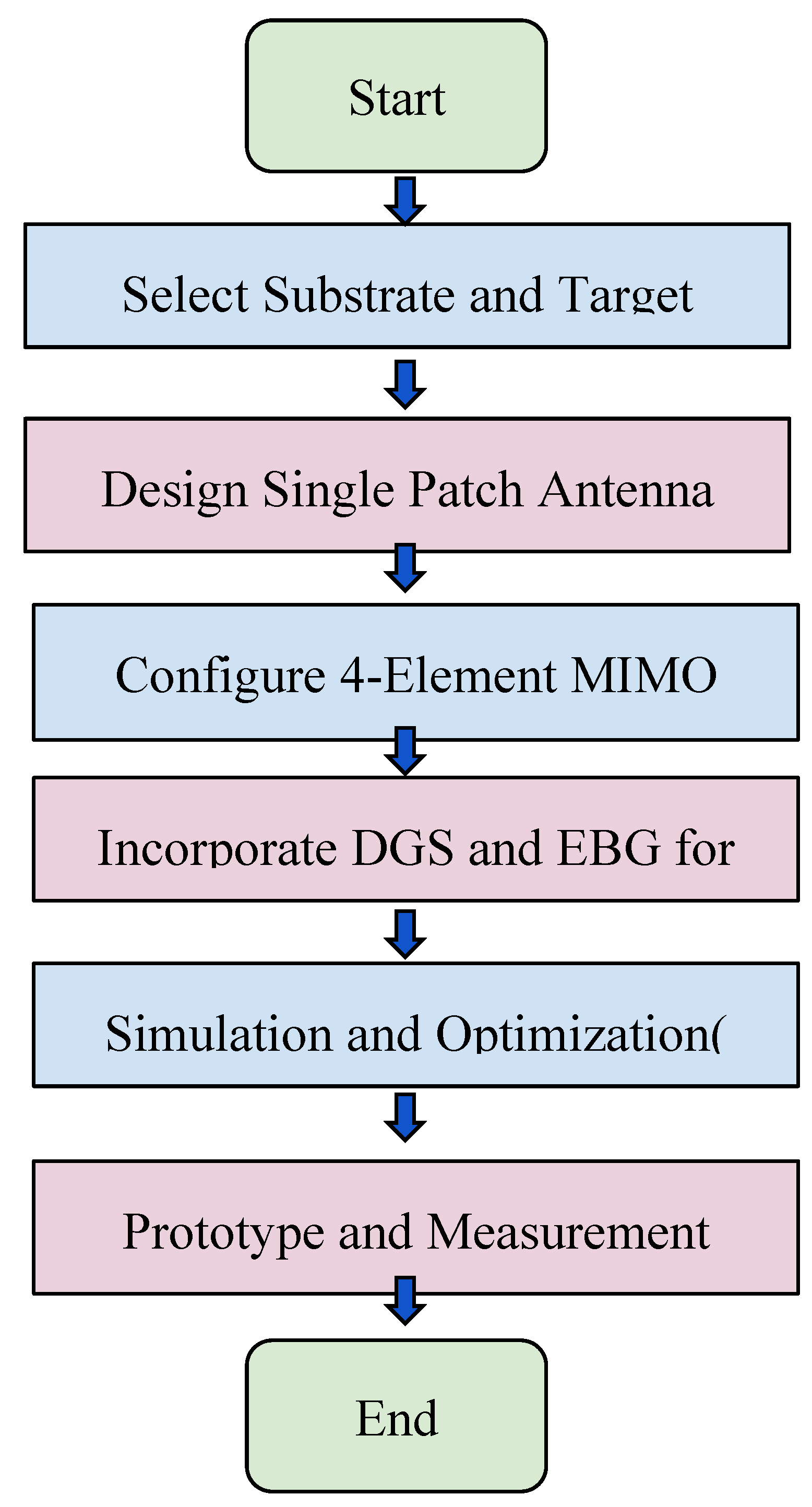
Figure 2.
Four- element (4 x 4) low profile MIMO patch Antenna.
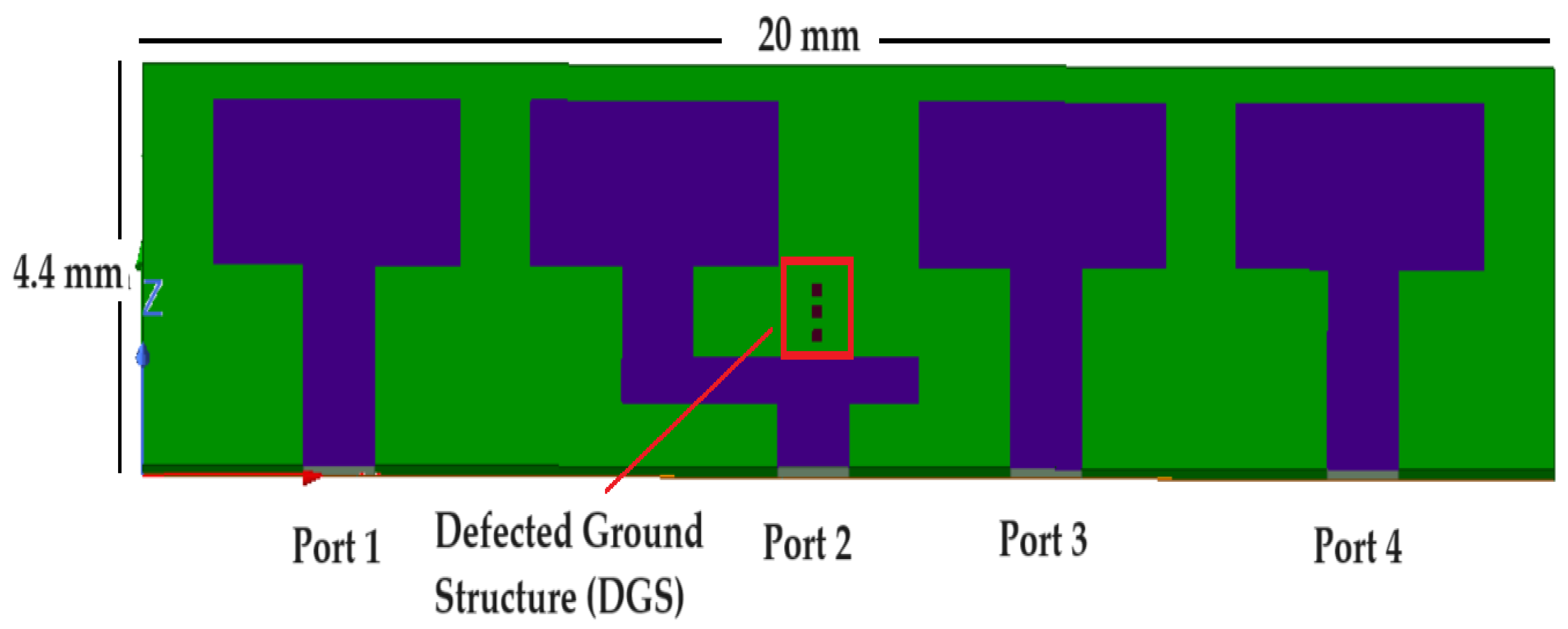

Table 1.
Simulated vs Measured Performance Comparison.
Disclaimer/Publisher’s Note: The statements, opinions and data contained in all publications are solely those of the individual author(s) and contributor(s) and not of MDPI and/or the editor(s). MDPI and/or the editor(s) disclaim responsibility for any injury to people or property resulting from any ideas, methods, instructions or products referred to in the content. |
© 2025 by the authors. Licensee MDPI, Basel, Switzerland. This article is an open access article distributed under the terms and conditions of the Creative Commons Attribution (CC BY) license (http://creativecommons.org/licenses/by/4.0/).
Copyright: This open access article is published under a Creative Commons CC BY 4.0 license, which permit the free download, distribution, and reuse, provided that the author and preprint are cited in any reuse.


