Preprint
Article

This version is not peer-reviewed.

Optimization of Adhesive Joint Design in Timber-Glass Systems: Enhancing Structural Performance with Primer Treatment

A peer-reviewed article of this preprint also exists.

Submitted:

18 December 2024

Posted:

19 December 2024

You are already at the latest version

Abstract

The increasing use of large glass surfaces in modern architecture requires robust adhesive solutions that balance aesthetic appeal with structural resilience, particularly in timber-glass applications. This study examines the influence of primer treatments on the shear performance of timber-glass adhesive joints, employing a combination of experimental testing and simulation techniques. Double-lap shear tests with epoxy adhesives assess the impact of various surface treatments on joint stiffness, shear stress distribution, and deformation. Additionally, a finite element model is developed to simulate joint behavior, evaluate failure modes, and analyze displacement patterns. Results indicate that primer applications notably enhance structural integrity by reducing displacement and increasing joint stability, thereby supporting more durable timber-glass assemblies. These findings offer valuable insights for advancing adhesive technologies in architectural components, enabling a closer alignment between structural performance and design innovation in timber-glass systems.

Keywords: 
;  ;  ;  ;  ;  

1. Introduction

In contemporary architecture, glass is an increasingly widely used design element thanks to its transparency and lightness. The current construction market asks for ever larger and seamless glass surfaces. This request can be satisfied by combining glass with other materials, such as steel, wood, aluminum and pultruded components thanks to adhesive unions. This allows to create clean and innovative designs, able to guarantee at the same time transparency and low energy consumption, also thanks to the technological advances in the double-glazing sector. This has led to the development of new techniques for glass panels assembling that allow architects to design aesthetically pleasing, structurally robust, and energy-efficient structures. One of the most investigated technologies is the potential of making a joint between glass and other materials. Several studies have been carried out on the feasibility of making joints between different materials [1,2], such as bonding timber and concrete for flooring applications [3], glass-steel [4] and glass-concrete [5] connections for full-scale beams, or combination of glass with Glass Fiber Reinforced Polymers (GFRP) [6] and plastic [7].
Compared to conventional mechanical joints, adhesive joints offer a number of advantages, including the ability to avoid stress concentration and distribute the external load over a larger area, resulting in light and high-performance structures [8,9,10]. In addition, adhesive joints are less prone to corrosion and can be used to join dissimilar materials, making them a versatile option for construction projects [4,11]. On the other hand, some major disadvantages of structural adhesive joints are: temperature and moisture sensitivity [12,13,14] (reduced performance, adhesive degradation or bond failure under high temperatures or moisture condition); bond strength dependence on material compatibility [15]; and challenging disassembly and repair [16], requiring specialized techniques, such as heating or chemical treatments, to break the bond (this can increase maintenance costs and limit the ease of future modifications or renovations). Additional aspects to be considered when choosing and designing an adhesive joint are the curing time (achieving the maximum strength can take hours or even days); the surface preparation requirements (a proper surface preparation is crucial for achieving strong adhesive bonds) and environmental considerations (some structural adhesives may contain hazardous substances (e.g., VOCs) and the disposal of adhesive waste must comply with environmental regulations).
An adhesive joint allows the peculiar properties of two different materials to be combined; in the case of a timber-glass joint, for example, the high stiffness of the glass is coupled with the tensile strength of the wood, resulting in ductile structures with good mechanical strength and durability [17,18,19]. This type of joint is particularly useful in situations where traditional mechanical fastening methods are not suitable or when a seamless appearance is desired. Moreover, the use of adhesive joints can result in cost savings and reduced environmental impact by minimizing the need for additional materials and reducing waste. Vallee et al. [20] used a case study of a pedestrian timber-glass bridge to show how to design and dimension complex bonded structures using traditional engineering methods. They found out that existing timber codes underestimate strength for crucial stress components related to bonding. Blyberg et al. [21] investigated the mechanical behavior, energy performance and Life Cycle Assessment (LCA) performance of various structural glass–timber composite building components (i.e., beams and shear walls), finding out that it is possible to obtain a non-brittle failure of these elements. In particular, the shear walls can be used as load bearing structures in 3–4 storeys, with no loss of energy performance and slight increase in LCA performance. Marchione et al. [22] tested the application of adhesive technology to a glazed panel for an innovative curtain wall with integrated frame. The mechanical performance of the adhesive joint depends on numerous factors, ascribable to both the nature of the bond itself (e.g., type of adhesive [23], geometry of the joint [24], bonded materials [3,25], etc.) and external factors, including environmental exposure (temperature and relative humidity) and service load (duration and type) [26,27,28]. Therefore, it is important to carefully consider all of these factors when selecting an adhesive and designing a bonded joint for a particular application. However, the major factor influencing the performance of the joint is the chemical bond between the polymer chains of the adhesive and the joining substrates to be joined. The strength of this bond, in turn, greatly affects the type of failure (e.g., adhesive, cohesive, stock-break, etc.). For this reason, surface preparation of the materials being joined plays a crucial role in the mechanical performance of the adhesive joint, meaning that proper surface preparation can improve adhesion and prevent premature failure of the bond [29,30,31,32,33]. Primers and adhesion promoters, for example, are useful surface treatments to improve surface tension at the interface and favor adhesion mechanisms. It is worth mentioning that the choice of surface treatment should be based on the specific materials to be bonded and the intended application.
According to what has been discussed thus far, the purpose of this study is to evaluate the performance of a wood-glass adhesive joint and the impact of pre-treatments such as primers and adhesion boosters have on it. This is done with the intention of assessing the feasibility of this type of application on an industrial scale, to be used for building components such as windows and curtain walls. For the latter, ductility is a key property, as it ensures them to withstand various loads and displacements (e.g., due to seismic and wind loads, thermal expansion and contraction, thermal cycling, moisture, Ultraviolet (UV) exposure, etc.) without experiencing failure, excessive deformation or premature degradation. This can fulfil various structural and environmental requirements, such as performance enhancement, occupant safety, and system longevity.
In this study, an experimental campaign of shear tests on double lap specimens is performed to evaluate the effects of three adhesion promoters (variously combined with each other) and three paints on the global mechanical performance of an adhesive joint composed of beechwood and glass adherends assembled with one epoxy structural adhesive. Finally, a Finite Element (FE) model, aimed to simulate the structural response of the adhesive joint, is developed and verified through the numerical-experimental comparison of the results.

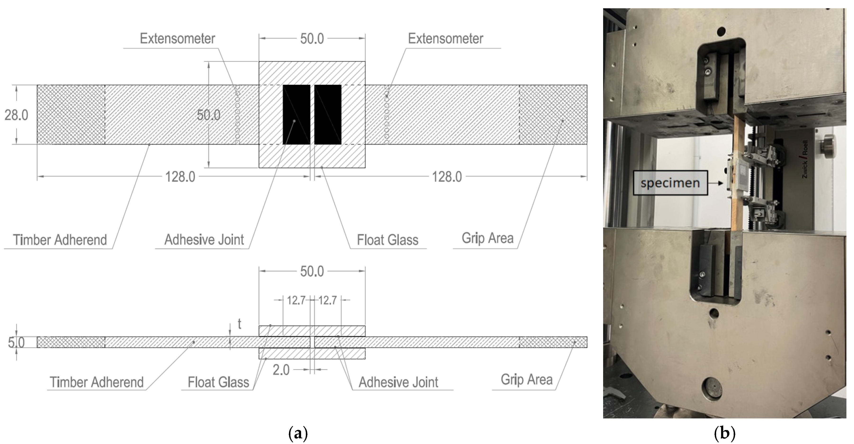
2. Materials and Methods

The mechanical performance of double lap adhesive joints is investigated by assessing the following mechanical parameters: ultimate load, shear strength and strain, displacements and ductility. Two different adherends are used in this work: transparent float glass panels, supplied by Vetreria Incicco (Italy), and beechwood, supplied by Pircher Oberland (Italy). The mechanical properties of the materials are listed in Table 1.
On the basis of the results of previous experimental studies on the shear performance of double lap adhesive joints assembled with different commercial structural adhesives [36,37,38,39], the 3M™ Scotch-Weld™ 7240 B/A adhesive [40] is selected as the most suitable for the present experimental campaign. The choice of this adhesive is dictated by its mechanical characteristics as well as its rheological properties. In fact, the ductility and resistance to artificial aging shown by this adhesive [38,41] make it the most suitable for the investigated purposes (i.e., windows and curtain walls). Table 2 shows the 3M™ Scotch-Weld™ 7240 mechanical properties listed in the technical datasheet.
The glass components of three out of the thirteen series are treated with paints, in particular one epoxy-based paint provided by Visa Colors (BGS 9200 white pearlescent paint), and two different acrylic-based paints supplied by Racing Colors (“Painting Bilayer RC9000” and “Paint Topcoat 2K satin + Cat”), whose properties and auxiliary components are reported in Table 3. Paints are used for purely aesthetic purposes as they guarantee the coverage of the adhesive joint, playing an important role in the design of the glazed component.
Before the bonding phase, all series except for the “untreated” and the “painted” ones are treated with a primer or a combination of primers on the glass side, and a primer or no primer at all on the timber side. The primers used in the study are: the 3M™ Silane Glass Primer, the 3M™ Adhesion Promoter 111 and the 3M™ Primer 94. The first one is a primer for glass which avoids moisture penetration at the adherend-adhesive interface; the second and third ones are suitable for various surfaces and can be used both on glass and timber substrate. Before the application of the primers, all surfaces of both timber and glass adherends are cleaned with denatured isopropyl alcohol, as recommended by the manufacturer. Physical and chemical properties of the three primers used in the study are retrieved from the product datasheets and listed in Table 4.
Five specimens are assembled for each series. All combinations tested and their nomenclature are reported in Table 5.
The test specimens are assembled in accordance with the ASTM D3528-16 standard [42]. The geometry of the test specimens is shown in Figure 1a. Since wood is an orthotropic material, the timber specimens are shaped in such a way as to have the greater dimension oriented in the direction of the fibres. Similarly, the joints are assembled so that the load is oriented to the fibres direction. The dimensions of the glass panels are 50 mm × 50 mm; the width of the beechwood profiles is 28.0 mm, with a length of 140 mm. Both the adherends have a thickness of 5 mm. The single bonding region has an area of 355.6 mm2 (28.0 mm × 12.7 mm). The thickness of the epoxy adhesive used is 0.30 mm, as recommended by the manufacturer.
Before testing, specimens are cured for 30 days under laboratory conditions of 20±1 °C and 50±4 % RH. Shear tests are conducted according to ISO 4587 [43] using a Zwick/Roell Z250 machine with a load cell of 250 kN under displacement control with a crosshead speed of 1.27 mm/min. All tests are performed under the room conditions previously described. The specimen displacement between the wood adherends is measured through a Zwick/Roell extensometer having a gauge length of 70 mm. The experimental setup is shown in Figure 1b.
At the end of the shear tests, all specimens are observed to characterize the failure modes according to the ASTM D 5573-99 standard [44]. For adhesive joints, the main failure modes are:
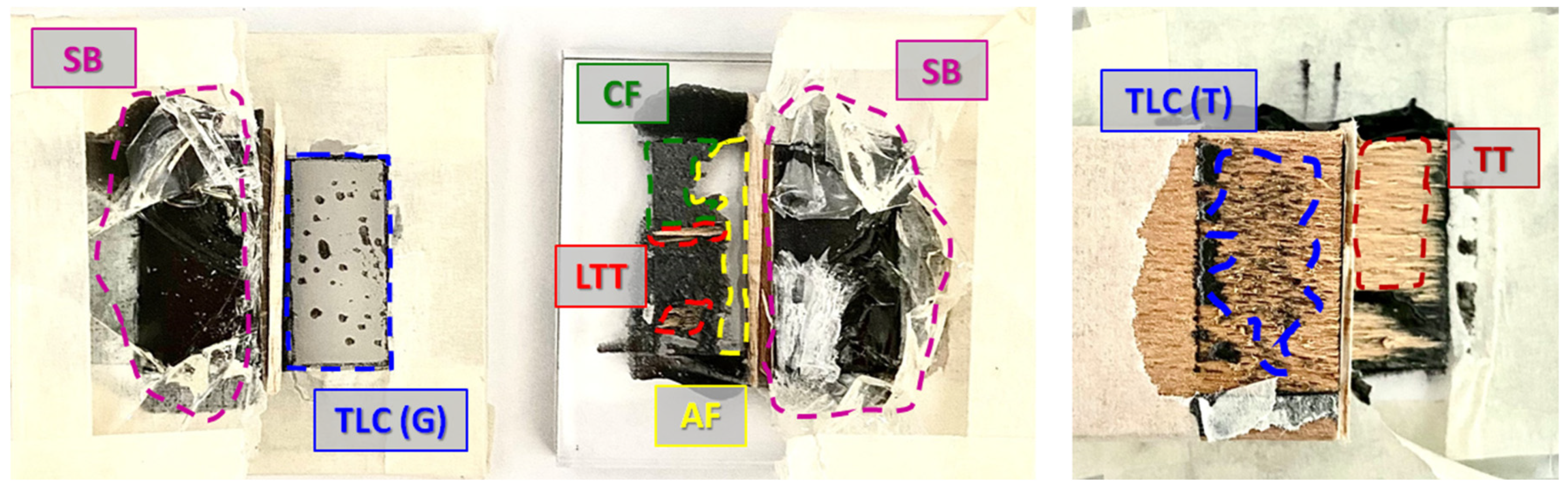
  • Adhesive Failure (AF): occurs at the interface between the adhesive and the adherend when the resistance of the interface (adhesion strength) is less than that of the adherend.
  • Cohesive Failure (CF): occurs within the adhesive, therefore the latter is present on both fracture surfaces.
  • Thin-Layer Cohesive Failure (TLC): cohesive failure occurring very close to the adhesive-substrate interface, characterized by a “light dusting” of adhesive on one substrate surface and a thick layer of adhesive left on the other.
  • Timber-Tear Failure (TT): failure occurring exclusively within the timber component, characterized by the presence of timber fibers on both ruptured surfaces.
  • Light-Timber-Tear Failure (LTT): timber failure characterized by a thin layer of timber fibers visible on the adhesive.
  • Stock-Break Failure (SB): break of the glass substrate outside the adhesively bonded-joint region, often occurring near it.
  • Mixed Failure (MF): any combination of two or more of the previous classes of failure mode described.
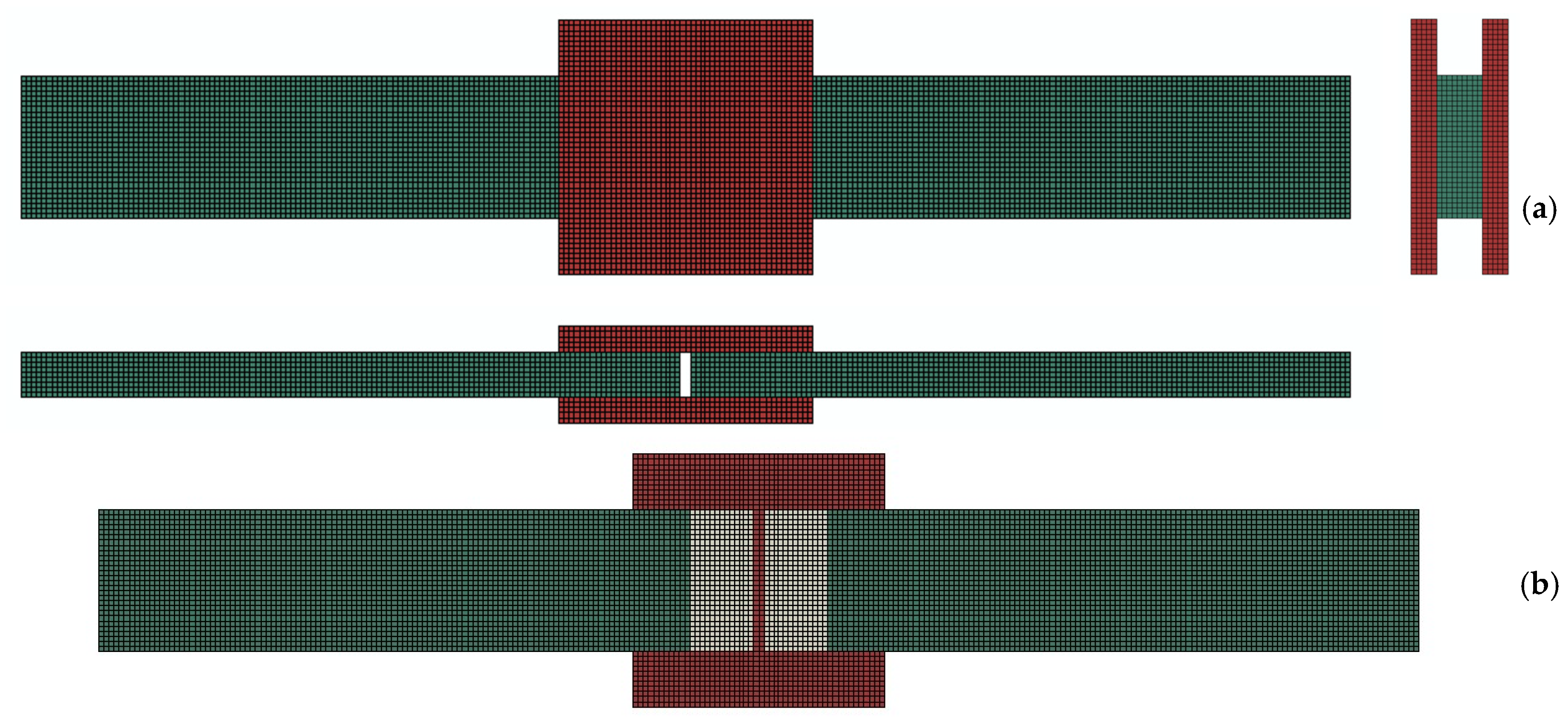
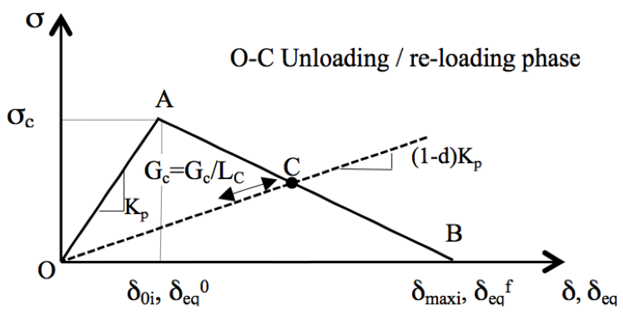
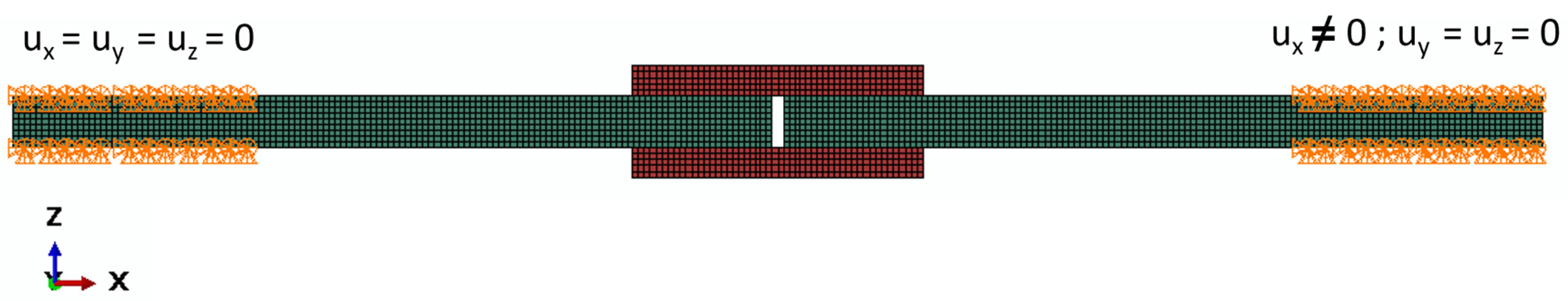
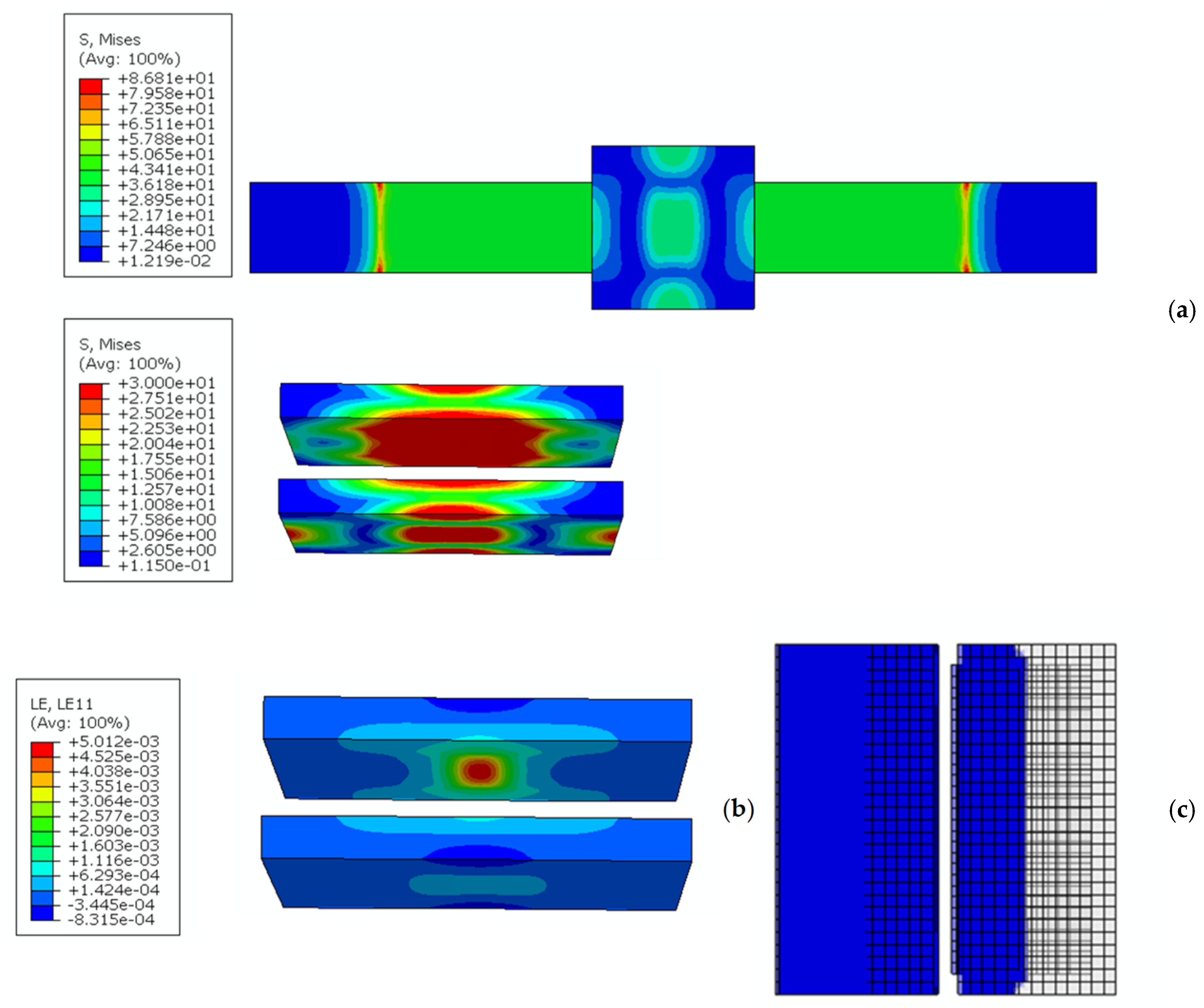
3. FE Model

Finite Element Method (FEM) is commonly used in literature [40,41,42,43] for the prediction of the structural behavior of such structural components as bonded joints. This section presents the modelling approach, based on FEM, for the simulation of the structural behavior of bonded joints. All analyses are performed through Abaqus® v. 2021 [44] commercial FE code. FE model, shown in Figure 2a refers to nominal dimensions shown in Figure 1a. FE model counts a total of 90520 linear hexahedral C3D8R elements (from Abaqus® finite element library), 8 nodes with 3 degrees of freedom, used for the modelling of all adherends, and 1456 linear hexahedral COH3D8 elements (from Abaqus® finite element library), 0.001 mm thick, 8 nodes with 3 degrees of freedom, used to simulate the adhesive. Cohesive elements layer, grey depicted in Figure 2b, opportunely placed on the adherend area covered by the adhesive, permits to predict both debonding initiation and evolution without providing to the FE model indications of the zone where the phenomenon starts [45]. Moreover, element nodes of adherends and adhesive layers are merged at the interfaces to guarantee their connectivity, being these characterized by the same in-plane mesh size.
Particular attention has been paid to the material characterization of the adhesive. In detail, the traction separation law is defined, considering for each opening mode, the bilinear law shown in Figure 3, where s represents stress and d the separation displacement.
According to Figure 3, the traction separation law consists of a first linear O-A path, characterized by a prefixed slope (penalty stiffness kp), where s c and d 0i represent the critical stress value and the displacement at the debonding initiation. The following A-B path represents the debonding evolution phase. The complete decohesion and then, the cohesive element deletion, occurs when d max is reached. To include within the simulation, the effects of combination of multiple opening modes on debonding, the quads damage criterion [44,45] and the power law [44,45] are implemented as initiation and evolution criteria, respectively. Concerning the former, debonding is assumed to initiate when a quadratic interaction function involving the nominal stress ratios reaches a value of one, Equation (1).
σ n σ n C 2 + σ s σ s C 2 + σ t σ t C 2 = 1 .
Where σ n C , σ s C , σ t C represent the critical values of the nominal stress σ n , σ s , σ t for induced in the adhesive under the normal, first or second shear modes. The latter, instead, permits to include within the simulation the effects of the interaction of the energies spent for the adherends debonding under mixed-mode conditions, Equation (2).
G n G n C α + G s G s C α + G t G t C α = 1 .
Where G n C , G s C and G t C are the critical fracture energies required to cause the debonding under normal, the first and the second shear opening modes, respectively. Specifically, the adhesive mechanical properties implemented within the FE model are summarized in Table 6.
Material properties of all adherends introduced in the FE model refer to Table 1. Boundary conditions are defined to reproduce the real ones, Error! Reference source not found.. According to Error! Reference source not found., ux, uy and uz represent the three translational degrees of freedom with respect to the reference system depicted in the same picture. All degrees of freedom of the orange highlighted nodes are fully constrained except for the ux ones of the right end, where a displacement is imposed. In details FE analysis has been carried out according to the implicit and large displacements schemes.

4. Results and Discussion

In this section, experimental and numerical results are illustrated and compared.

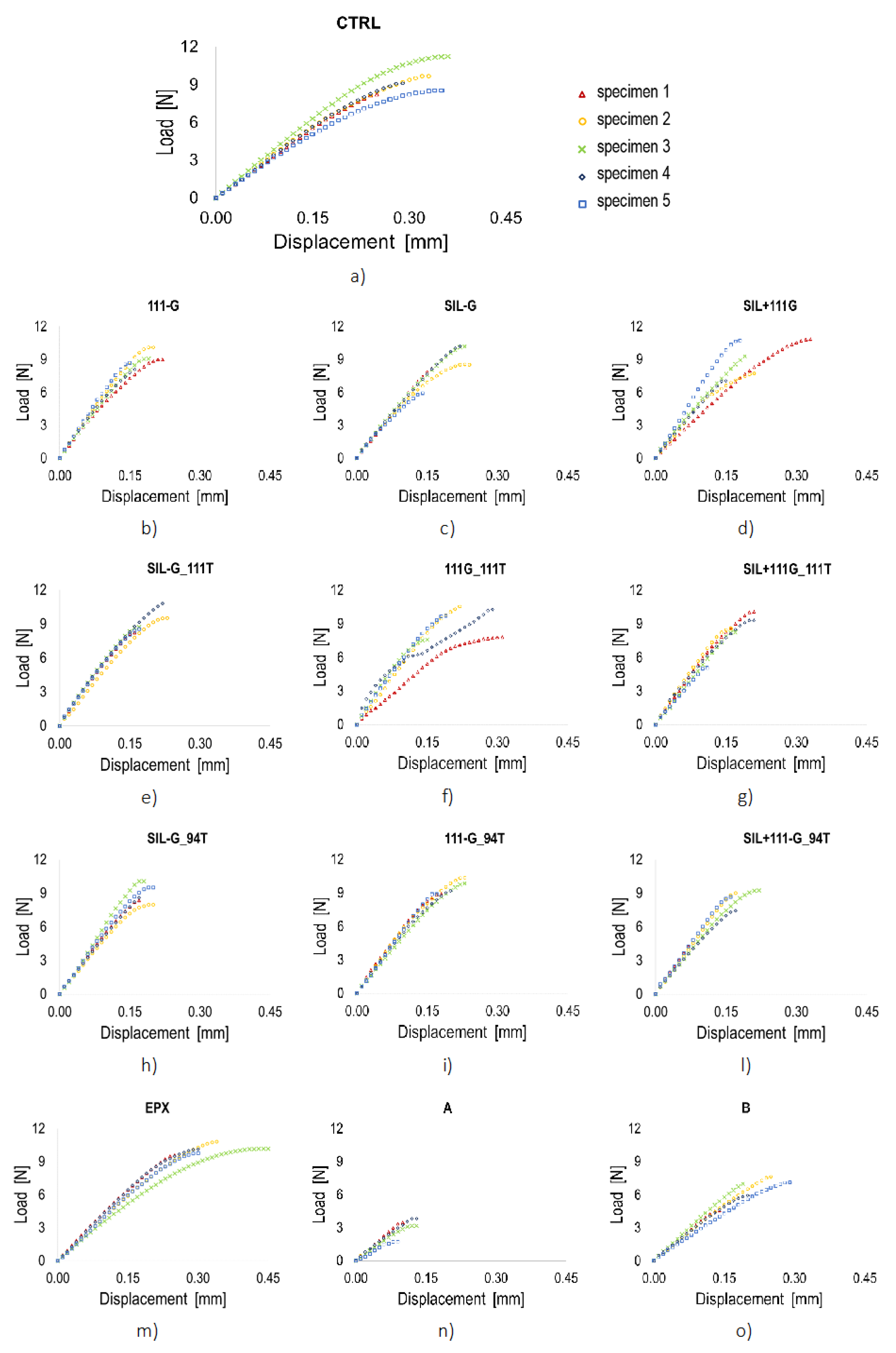
4.1. Experimental Results

The experimental results are discussed in terms of ultimate strength, displacement, shear stress (τ, ratio between load and total adhesive area), shear strain (γ, ratio between displacement and thickness of the adhesive layer), and global stiffness (k, ratio between load and displacement) of the joint. Failure modes are also analysed. For the calculation of the stiffness, only the linear portion of each curve is used since the beginning of nonlinearity indicates the occurrence of damage in the adhesive joint. Figure 5 reports the load-displacement curves for all specimen series up to the failure point, namely until the last load increment is recorded.
A detailed description of the failure modes, specimen by specimen, is provided in Table 7, while Figure 6 depicts all the observed failure modes, using specimens CTRL_1, CTRL_3 and SIL-G_5 as an example.
The results obtained are compared in terms of average values and summarized in Table 8, where the prevalent failure modes are also listed.
The highest failure load is achieved by the series treated with the epoxy paint, while the two acrylic painted series register the worst behavior; in particular, for paint A (Figure 5n), a drastic reduction in ultimate load is observed (70% lower than to the CTRL series, Figure 5a), probably due to the inhibition of the cohesive process between the adhesives caused by the interposition of the paint layer. All other series have a slightly higher failure load than the untreated series, except for the SIL-G_94T (Figure 5h) series (similar maximum load) and the SIL-G (Figure 5b) and SIL+111G_94T (Figure 5l) series (slightly lower maximum load). The untreated series exhibits the highest ultimate displacement, comparable only to that of the EPX series (Figure 5m); all other series (A excluded) have a maximum displacement equal to approximately two thirds of that of the untreated series. The EPX series also has the highest shear stress and strain; the average value of shear strain of the EPX series is comparable only to that of the untreated series (Figure 5a), while the shear strain of all other series with primers is halved (0.53 ≤ γ ≤0.68). The highest values of the global stiffness (around 50 kN/mm) are reached by 4 series for which at least one primer on the glass side is used (111G – Figure 5c, SIL-G_111T – Figure 5e, SIL+111G_111T – Figure 5g, and SIL-G_94T Figure 5h). This results from the improved connection of the adhesive to the glass surface made possible using adhesion promoters. As a matter of fact, due to the environmental exposure, the bonding surface on the glass side may be subject to moisture penetration at the interface between the glass adherend and the adhesive. This causes a weakening of the bonding and may lead to the detachment of the adhesive from the glass. The use of silane primer effectively counteracts this phenomenon. Moreover, the stiffness of the untreated series (Figure 5a) is comparable to that of the painted series, particularly the acrylic types (Figure 5n,o). The series treated with acrylic paint type A (Figure 5n) shows the worst results for all the parameters considered, followed by type B (Figure 5o) series.
Once the shear tests have been completed, the failure modes of all specimens are. Only 18 out of the total 65 specimens show a single failure mode, while in all the others the failure occurs as a mix of two to four different mechanisms. The most recurring one is the Stock-Break (SB) failure mode, which occurs in three to five out of five cases for all series, except acrylic-treated specimens. The latter all show an adhesive type failure mode AF, alone (only for the A type) or in combination with a thin-layer cohesive fracture; both those collapse mechanisms occur at the interface between the adhesive and the glass, which is the most undesirable form, since it indicates low bonding forces between adherends. The TLC failure mode takes place close to both interfaces, but at the timber interface is two times more frequent. The AF never happens at the timber interface, which is ascribable to the fibrous and porous nature of the wood. In fact, the latter makes possible the development of greater cohesion forces between the adhesive and the timber adherends. The presence of an interface characterized by a limited roughness (i.e., glass outer adherends) determines the presence of a preferential sliding plane for the specimen according to an adhesive failure AF.

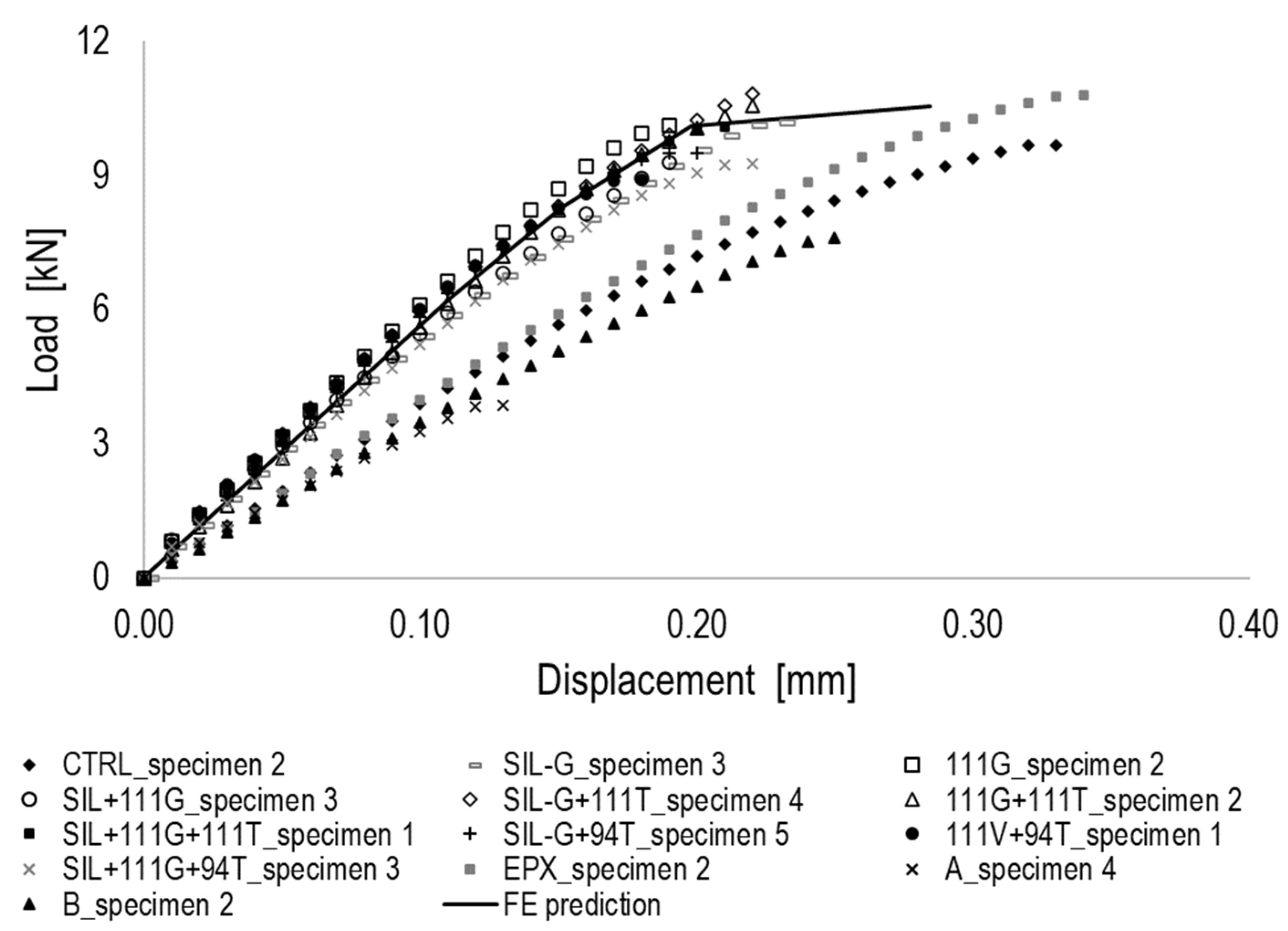
4.2. Numerical Results and Experimental Data Comparison

As aforementioned, material characterization in FE model does not consider the effects of both adhesive promoters and paints, but it refers only to material properties reported in Table 1 and Table 2 [40]. Results postprocessing is performed to identify the level of accuracy of the developed FE model in simulating the structural behavior of all specimens series. For this purpose, a representative load vs. displacement curve for each specimen series, has been selected and reported in Figure 7, where the curve provided by FE simulation is also reported. According to Figure 7, it can be noticed that all series where adhesive promoters are used are quite overlapped. CTRL, A, B and EPX specimen curves, instead, appear dissociated from the previous, being characterized by a reduced stiffness. The predicted curve (solid line) is quite overlapped to the curves group linked to the specimens where adhesive promoters are used. It must be highlighted that FE model, in this case, permitted the simulation of an ideal specimen, characterized by a uniform layer of glue, by the lack adherends misalignment and all those imperfections usually associated to specimens manual manufacturing. Since the good and acceptable level of accuracy provided by the FE simulation with respect to all series including adhesive promoters, it can be concluded that the usage of such additives permits mitigating imperfections in specimens.
In terms of prevalent failure mode, FE simulation appears coherent with those experimentally detected. The main reason of collapse of the joint, in fact, lies in the glass break. Figure 8a shows the von Mises stress distribution over the whole joint with focus of the glass adherends. According to Figure 8a, it can be observed that the maximum stress amplitude is reached. In Figure 8b, showing the deformations distribution at the glass adherends, it can be observed that axial (with respect to the joint) strain component reaches the typical value of elongation at break, equals to 5%. Following the glass break, due to the load redistribution, the adhesive layers start to fail, as depicted in the contour plot shown in Figure 8c extracted some increments later. According to Figure 8c, blue zones represent the undamaged areas of the adhesive. Fully collapsed finite elements are deleted during the simulation. As demonstrated by Figure 9, the adhesive failure is mainly induced by mixed opening modes with a prevalence of the first shear mode (Mode II), followed by Mode I. All stress components are measured before and after the finite elements deletion along the path illustrated in Figure 9.

5. Conclusions

In this study, the influence of different pre-treatments and coatings on the mechanical behaviour of an adhesive joint between glass and timber is investigated in order to identify an appropriate technique for including adhesive junctions in the industrial production of building components such as windows, glazing panels for curtain walls, etc. In addition, a FE model has been developed and verified through an experimental-numerical comparison of the results.
The results highlight that:
1)
The pre-treatments on the glass and/or timber side of the bonded joint reduce the maximum displacement, shear stress and shear strain. They may also contribute to increase the maximum failure load of the joint, but this behaviour is not observed for all the tested series; in particular, adhesion promoters (111 and 94) seem to have a better effect than moisture-inhibitor (Silane) in this respect. As a consequence of the decrease of the ultimate displacement, all pre-treated series have higher stiffness than the untreated ones. These treatments, in fact, improve surface adhesion at the adherend-adhesive interface, which in turn enhances load transmission between the adherents up to the maximum permissible stress of the glass, before the adhesive failure (AF) occurs. This aspect of stiffness is relevant according to the different fields of application (i.e., depending on the displacements that the joint can bear, a combination is more or less suitable for a specific purpose).
2)
The behaviour of the painted joint strongly depends on the type of paint used on the glass: a paint of the same nature of the adhesive (i.e., epoxy paint) can increase the ultimate load but has no significant effect on the remaining considered parameters (as summarized in Table 8), nor on the type of failure mechanisms. Conversely, the use of an acrylic paint causes a worsening of the overall mechanical behaviour and shifts the collapse mode from glass failure to interface failure.
3)
According to the results of the numerical modelling, it can be concluded that the simulation appears to be more representative of all those series where adhesive promoters are used. This aspect can be addressed to the fact that the usage of adhesive promoters reduces the effects on the joint structural behaviour of the uncertainties affecting all specimens because of the manufacturing process, which cannot be easily included in the modelling.

Author Contributions

Conceptualization, P.M.; methodology, P.M., R.A., F.M., A.D.L., and R.S.; software, A.D.L.; validation, R.A. and A.D.L.; formal analysis, R.A. and A.D.L..; investigation, R.A., A.D.L. and R.S; resources, P.M., F.C. and R.S.; data curation, R.A., F.M. and A.D.L.; writing—original draft preparation, R.A. and A.D.L.; writing—review and editing, R.A., A.D.L. and R.S.; visualization, R.A.; supervision, P.M, F.C. and R.S.; project administration, R.A.. All authors have read and agreed to the published version of the manuscript.

Funding

This research received no external funding.

Data Availability Statement

The data supporting the findings of this study are available upon request.

Conflicts of Interest

The authors declare no conflicts of interest.

References

  1. Vallée, T.; Tannert, T.; Fecht, S. , “Adhesively bonded connections in the context of timber engineering–A Review,” Journal of Adhesion, vol. 93, no. 4. Taylor and Francis Inc., pp. 257–287, Mar. 21, 2017. [CrossRef]
  2. Martens, K.; Caspeele, R.; Belis, J. , “Development of composite glass beams - A review,” Engineering Structures, vol. 101. Elsevier Ltd., pp. 1–15, Oct. 05, 2015. [CrossRef]
  3. Tannert, T.; Gerber, A.; Vallee, T., “Hybrid adhesively bonded timber-concrete-composite floors,” Int J Adhes Adhes, vol. 97, no. November 2019, p. 102490, 2020. [CrossRef]
  4. MacHalická, K.; Horčičková, I.; Eliášová, M. , “Shear adhesive connections for glass structures,” IOP Conf Ser Mater Sci Eng, vol. 96, no. 1, 2015. [CrossRef]
  5. Freytag, B. , “Glass-concrete composite technology,” Structural Engineering International: Journal of the International Association for Bridge and Structural Engineering (IABSE), vol. 14, no. 2, pp. 111–117, 2004. [CrossRef]
  6. Speranzini, E.; Agnetti, S. , “Strengthening of glass beams with steel reinforced polymer (SRP),” Compos B Eng, vol. 67, pp. 280–289, 2014. [CrossRef]
  7. Hildebrand, J.; Werner, F. , “GLASS-PLASTIC HYBRID CONSTRUCTION,” 2006.
  8. Marchione, F. , “Stress distribution in double-lap adhesive joints: Effect of adherend reinforcement layer,” Int J Adhes Adhes, vol. 105, Mar. 2021. [CrossRef]
  9. Marchione, F. , “Effect of hollow adherends on stress peak reduction in single-lap adhesive joints: FE and analytical analysis,” Journal of Adhesion, vol. 98, no. 6, pp. 656–676, 2022. [CrossRef]
  10. Adams, R.D.; Peppiatt, N.A. , “Stress analysis of adhesive-bonded lap joints,” Journal of strain analysis, vol. 9, no. 3, pp. 158–196, 1974.
  11. Machalická, K.; Vokáč, M.; Eliášová, M. , “Influence of artificial aging on structural adhesive connections for façade applications,” Int J Adhes Adhes, vol. 83, no. March, pp. 168–177, 2018. [CrossRef]
  12. Jasiūnas, L.; Peck, G.; Bridžiuvienė, D.; Miknius, L. , “Mechanical, thermal properties and stability of high renewable content liquefied residual biomass derived bio-polyurethane wood adhesives,” Int J Adhes Adhes, vol. 101, Sep. 2020. [CrossRef]
  13. Bartkowiak, M.; Czech, Z.; Mozelewska, K.; Nowak, M. , “Influence of thermal reactive crosslinking agents on the tack, peel adhesion, and shear strength of acrylic pressure-sensitive adhesives,” Polym Test, vol. 90, Oct. 2020. [CrossRef]
  14. Banea, M.D.; Da Silva, L.F.M.; Campilho, R.D.S.G., “Effect of temperature on the shear strength of aluminium single lap bonded joints for high temperature applications,” J Adhes Sci Technol, vol. 28, no. 14–15, pp. 1367–1381, July 2014. [CrossRef]
  15. Pethrick, R.A. , “Design and ageing of adhesives for structural adhesive bonding – A review,” Proceedings of the Institution of Mechanical Engineers, Part L: Journal of Materials: Design and Applications, vol. 229, no. 5, pp. 349–379, 2015.
  16. Jeevi, G.; Nayak, S.K.; Kader, M.A. , “Review on adhesive joints and their application in hybrid composite structures,” Journal of Adhesion Science and Technology, vol. 33, no. 14. Taylor and Francis Ltd., pp. 1497–1520, Jul. 18, 2019. [CrossRef]
  17. Pequeno, J.M.; Cruz, P.J.S. , “Structural Timber-Glass Linear System: Characterization & Architectural Potentialities,” Glass Performance Days 2009 - Proceedings of the 11th International Conference, pp. 344–348, 2009.
  18. Erik. Eriksson, J & Ludvigsson, M & Dorn, Michael & Enquist, Bertil & Serrano, “Load bearing timber glass composites – A WoodWisdom-Net project for innovative building system,” in COST Action TU0905 Mid-term Conference on Structural Glass, 2013, p. 269. [CrossRef]
  19. Cruz, P.J.S.; Pequeno, J. , “Timber-Glass Composite Beams: Mechanical Behaviour & Architectural Solutions,” Challenging Glass, pp. 439–448, 2008.
  20. Vallee, T.; Grunwald, C.; Milchert, L.; Fecht, S. , “Design and dimensioning of a complex timber-glass hybrid structure: the IFAM pedestrian bridge,” Glass Structures & Engineering, vol. 1, no. 1, pp. 3–18, Jun. 2016. [CrossRef]
  21. Blyberg, L.; et al. , “Glass, timber and adhesive joints – Innovative load bearing building components,” Constr Build Mater, vol. 55, pp. 470–478, Mar. 2014. [CrossRef]
  22. Marchione, F.; Agliata, R.; Munafò, P. , “Application of adhesive technology to a new type of glazed panel for curtain walls with an integrated frame,” TEMA, vol. 8, no. 2, 2022. [CrossRef]
  23. Blyberg, L.; Serrano, E.; Enquist, B.; Sterley, M. , “Adhesive joints for structural timber/glass applications: Experimental testing and evaluation methods,” Int J Adhes Adhes, vol. 35, pp. 76–87, 2012. [CrossRef]
  24. Kozłowski, M.; Kadela, M.; Hulimka, J. , “Numerical Investigation of Structural Behaviour of Timber-Glass Composite Beams,” Procedia Eng, vol. 161, pp. 990–1000, 2016. [CrossRef]
  25. Rudawska, A. , “Adhesive joint strength of hybrid assemblies: Titanium sheet-composites and aluminium sheet-compositesExperimental and numerical verification,” Int J Adhes Adhes, vol. 30, no. 7, pp. 574–582, 2010. [CrossRef]
  26. Van Lancker, B.; et al. , “Durability of adhesive glass-metal connections for structural applications,” Eng Struct, vol. 126, pp. 237–251, 2016. [CrossRef]
  27. Sousa, J.M.; Correia, J.R.; Firmo, J.P.; Cabral-Fonseca, S.; Gonilha, J. , “Effects of thermal cycles on adhesively bonded joints between pultruded GFRP adherends,” Compos Struct, vol. 202, no. February, pp. 518–529, Oct. 2018. [CrossRef]
  28. Schneider, B.; Beber, V.C.; Schweer, J.; Brede, M.; Mayer, B. , “An experimental investigation of the fatigue damage behaviour of adhesively bonded joints under the combined effect of variable amplitude stress and temperature variation,” Int J Adhes Adhes, vol. 83, no. March, pp. 41–49, 2018. [CrossRef]
  29. Min, J.; Wan, H.; Carlson, B.E.; Lin, J.; Sun, C. , “Application of laser ablation in adhesive bonding of metallic materials: A review,” Opt Laser Technol, vol. 128, no. February, p. 106188, 2020. [CrossRef]
  30. Žigon, J.; et al. , “Enhancement of strength of adhesive bond between wood and metal using atmospheric plasma treatment,” Cellulose, vol. 27, no. 11, pp. 6411–6424, 2020. [CrossRef]
  31. Worpenberg, C.; Stiesch, M.; Eisenburger, M.; Breidenstein, B.; Busemann, S.; Greuling, A. , “The effect of surface treatments on the adhesive bond in all-ceramic dental crowns using four-point bending and dynamic loading tests,” J Mech Behav Biomed Mater, vol. 139, p. 105686, Mar. 2023. [CrossRef]
  32. Guo, L.; Liu, J.; Xia, H.; Li, X.; Zhang, X.; Yang, H. , “Effects of surface treatment and adhesive thickness on the shear strength of precision bonded joints,” Polym Test, vol. 94, p. 107063, Feb. 2021. [CrossRef]
  33. Zou, X.; et al. , “Laser surface treatment to enhance the adhesive bonding between steel and CFRP: Effect of laser spot overlapping and pulse fluence,” Opt Laser Technol, vol. 159, p. 109002, Apr. 2023. [CrossRef]
  34. Consiglio Nazionale delle Ricerche (CNR), CNR-DT 210/2013 - Istruzioni per la Progettazione, l’Esecuzione ed il Controllo di Costruzioni con Elementi Strutturali di Vetro. Italy, 2013.
  35. INTERNATIONAL STANDARD ISO, 13061-6 Physical and mechanical properties of wood — Test methods for small clear wood specimens — Part 6: Determination of ultimate tensile stress parallel to grain. INTERNATIONAL STANDARD ISO, 2014.
  36. Marchione, F.; Munafò, P. , “Influence of high temperature exposure on the mechanical performance of double-lap adhesive joints between glass and aluminium adherends,” Constr Build Mater, vol. 299, Sep. 2021. [CrossRef]
  37. Marchione, F.; Chiappini, G.; Munafò, P. , “Effect of temperature and relative humidity on the shear performance of double-lap adhesive joints between steel and glass adherends,” Journal of Building Engineering, vol. 45, Jan. 2022. [CrossRef]
  38. Marchione, F.; Munafò, P. , “Effect of thermal aging on the mechanical performance of timber-timber single-lap adhesive joints,” Int J Adhes Adhes, vol. 108, Jul. 2021. [CrossRef]
  39. Marchione, F.; Munafò, P. , “Experimental investigation on timber-glass double-lap adhesive joints reinforced with nylon fabric,” Constr Build Mater, vol. 275, Mar. 2021. [CrossRef]
  40. 3MTM, “Scotch-WeldTMStructural Adhesive 7240 B/A FR Preliminary Product Data Sheet,” 2018.
  41. Marchione, F.; Munafò, P. , “Experimental investigation on timber-glass double-lap adhesive joints,” Int J Adhes Adhes, vol. 106, Apr. 2021. [CrossRef]
  42. ASTM, D3528-96 Standard Test Method for Strength Properties of Double Lap Shear Adhesive Joints by Tension Loading. USA, 2016.
  43. ISO, 4587:2003 Adhesives — Determination of tensile lap-shear strength of rigid-to-rigid bonded assemblies. 2003.
  44. ASTM, D5573 Standard Practice for Classifying Failure Modes in Fiber-Reinforced-Plastic (FRP) Joints 1. USA, 1999.
  45. Lamanna, G.; Perrella, M.; Opran, C.G. , “Numerical and Experimental Investigation on the Influence of Tightening in a Hybrid Single Lap Joint” Macromolecular Symposia vol. 396(1), 2100010. 2021.
  46. Lamanna, G.; Opran, C.G. , “Numerical Characterization of Pretensioning of a Hybrid Joint Under Longitudinal Load, Macromolecular Symposia vol. 396(1), 2100009. 2021.
  47. Lamanna, G.; Ion, S.M.; Opran, C.G., “Flexural Effects Evaluation on Hybrid Joints Under Uniaxial Tensile Load” Macromolecular Symposia, 396(1), 2100007. Vol. 2021.
  48. Caputo, F.; Lamanna, G.; Soprano, A. , “Effects of tolerances on the structural behavior of a bolted hybrid joint”, Key Engineering Materials vol. 488-489, pp. 565–568. 2012.
  49. Abaqus/CAE User Manual v. 2021 - Dassault Systèmes.
  50. Caputo, F.; De Luca, A.; Lamanna, G.; Borrelli, R.; Mercurio, U. , “Numerical study for the structural analysis of composite laminates subjected to low velocity impact”, Composites: Part B vol. 67, 296–302. 2014.
Figure 1. Double lap specimen geometry (mm), section and plan view (a) and test setup with specimen ready to be tested (b).
Preprints 143391 g001
Figure 2. FE model (a) and Cohesive elements layer (b).
Preprints 143391 g002
Figure 3. Cohesive traction separation law [45].
Preprints 143391 g003
Figure 4. Boundary conditions.
Preprints 143391 g004
Figure 5. Load-displacement curves of all treated double-lap joints.
Preprints 143391 g005
Figure 6. Failure modes of specimens CTRL_1 (left), CTRL_3 (middle) and SIL-G_5 (right).
Preprints 143391 g006
Figure 7. Numerical-experimental comparison of all treated double-lap joints.
Preprints 143391 g007
Figure 8. Von Mises distribution (units in MPa) (a), Strain distribution (b) and Adhesive layers (c).
Preprints 143391 g008
Figure 9. Adhesive opening modes.
Preprints 143391 g009
Table 1. Mechanical characteristics of the adherends reported by manufacturers.
Glass [34] Beechwood [35]
Thermal coeff. of expansion Young Modulus Tensile strength Young Modulus Tensile strength
α (°C-1) E (GPa) σR (MPa) E (GPa) σR (MPa)
9 × 10⁻⁶ 75 30 1.5 90
Table 2. Mechanical characteristics of the 3M™ Scotch-Weld™ 7240 B/A adhesive reported by manufacturer.
Chemical nature two-part toughened epoxy base + modified amine accelerator
Viscosity - thixotropic
Work life Wl (min) 45
Application temperature At (°C) 15÷30
Glass transition temperature Tg (°C) 66.87
Service temperature St (°C) -40÷80
Shear strength τ (MPa) 6.2 – 24.3*
Young Modulus in compression Et (MPa) 3500-4000
Use - semi-structural
* depending on the substrate.
Table 3. Properties of the paints.
Epoxy-based Acrylic-based - type A Acrylic-based – type B
Colour silver black black
Type 2-compounds pearlescent paint for glass Bilayer 100% solvent-based high coverage High Solids, solvent-based 2-component, satin finish
Composition 1 part paint + 0.6 diluent* + 0.45 catalyst** 1 part paint + 0.5 diluent*** 1 part paint + 0.2 catalyst****
Auxiliary components * DT 810 Epoxy Thinner by Visa Colors
** AM 85 Glossy Hardener
*** Disolvente acrìlico RU RAC medio **** Catalizador DCP9156 high adherence by Racing colors (included with the paint)
Table 4. Physical and chemical properties of the primers.
Silane 111 94
Main ingredient (% by Weight) isopropyl alcohol
(80 – 95)*
propan-2-ol
(98 – 100)
cyclohexane
(30 – 60)*
Boiling point (°C) 82.2 82.4 76.7
Flashpoint (°C) 11.7 11 -17.2
Density (g/ml) 0.80 0.79 0.82
Vapor Pressure (mmHg) 43 (at 25 ºC) 330 (at 20 ºC) 68 (at 20 ºC)
Relative Vapor Density 2.07 2.1 no data available
* Trade Secret.
Table 5. Tested combinations of beechwood-glass joints with various adhesion promoters.
CTRL Untreated
SIL-G Silane on the glass side
111G Primer 111 on the glass side
SIL+111G Silane + Primer 111 on the glass side
SIL-G_111T Silane on the glass side and Primer 111 on the timber side
111G_111T Primer 111 on the glass side and Primer 111 on the timber side
SIL+111G_111T Silane + Primer 111 on the glass side and Primer 111 on the timber side
SIL-G_94T Silane on the glass side and Primer 94 on the timber side
111G_94T Primer 111 on the glass side and Primer 94 on the timber side
SIL+111G_94T Silane + Primer 111 on the glass side and Primer 94 on the timber side
EPX Glass treated with Epoxy paint
A Glass treated with Acrylic paint – type A
B Glass treated with Acrylic paint – type B
Table 6. Numerical characterization of adhesive: material properties of adhesive layer.
Longitudinal Young’s Modulus En [MPa] 4000
Transversal Young’s Moduli Es=Et [MPa] 1350
Nominal stress I mode σ n [MPa] 42
Nominal stress II mode σ s [MPa] 15
Nominal stress III mode σ t [MPa] 15
Critical fracture energy, mode I G n C Jm-2 380
Critical fracture energy, mode II G s C Jm-2 190
Critical fracture energy, mode III G t C Jm-2 190
Table 7. Failure modes. The (G) and (T) means that the failure happens at the glass and timber interface, respectively.
Series Specimen 1 Specimen 2 Specimen 3 Specimen 4 Specimen 5
CTRL SB + TLC (G) SB SB + AF (G) + CF + LTT SB SB + CF + LTT
SIL-G SB SB + TT + TLC (T) SB + LTT + TLC (T) SB + TT TT + LTT + TLC (T/G)
111G SB + TT + TLC (G) SB + TLC (T/G) + LTT SB + TT + TLC (G) SB SB + TT
SIL+111G SB + LTT + TLC (T) SB SB SB SB + LTT + TLC (T)
SIL-G_111T SB SB + TLC (T) + LTT+ AF (G) CF + LTT + TLC (T/G) SB SB + TT + LTT + TLC (T)
111G_111T SB + TT AF (G) + LTT + TLC (T) SB + LTT + TLC (T) SB SB + TLC (T) + LTT
SIL+111G_111T TT + LTT SB + TT SB + TT LTT SB + TLC (T) + LTT
SIL-G_94T SB TLC (T) + LTT SB + TT + TLC (T) SB SB + TLC (T) + LTT
111G_94T TLC (G) + LTT SB + LTT + TLC (T) SB + LTT + TLC (T) SB + LTT + TLC (T) SB + TT
SIL+111G_94T SB + TLC (T) SB + TT + LTT + TLC (T) SB + LTT + TT + TLC (T) SB + TLC (T) + LTT SB + LTT + TLC (T)
EPX SB SB SB + CF + LTT + TLC (T) SB + LTT + TLC (T) SB + LTT + TLC (T)
A AF (G) + TLC (G) AF (G) + TLC (G) AF (G) AF (G) AF (G)
B TLC (G) + AF (G) TLC (G) + SB + AF (G) TLC (G) + AF (G) TLC (G) + AF (G) TLC (G) + AF (G)
Table 8. Mechanical properties and failures mechanisms of beechwood-float glass double-lap adhesive joints.
Series Load max Displ max τmax γmax k Failure
Modes*
(kN) (mm) (MPa) (-) (kN/mm)
CTRL 8.90 ± 0.64 0.31 ± 0.05 7.26 ± 0.50 1.09 ± 0.16 30.39 ± 3.66 3 MF + 2 SB
SIL-G 8.61 ± 1.06 0.20 ± 0.05 6.67 ± 0.83 0.66 ± 0.16 44.62 ± 5.97 4 MF + 1 SB
111G 9.01 ± 0.73 0.18 ± 0.03 6.98 ± 0.57 0.62 ± 0.08 50.73 ± 5.97 4 MF + 1 SB
SIL+111G 9.13 ± 1.47 0.18 ± 0.03 7.07 ± 1.14 0.63 ± 0.04 46.21 ± 10.89 3 SB + 2 MF
SIL-G_111T 9.18 ± 1.04 0.19 ± 0.03 7.11 ± 0.80 0.58 ± 0.09 49.88 ± 4.48 3 MF + 2 SB
111G_111T 9.20 ± 1.41 0.23 ± 0.07 7.13 ± 1.09 0.66 ± 0.21 43.19 ± 11.77 4 MF + 1 SB
SIL+111G_111T 9.06 ± 0.82 0.17 ± 0.02 7.02 ± 0.64 0.53 ± 0.07 50.27 ± 3.02 4 MF + 1 LTT
SIL-G_94T 8.91 ± 0.87 0.18 ± 0.01 6.90 ± 0.67 0.60 ± 0.04 50.18 ± 6.09 3 MF + 2 SB
111G_94T 9.44 ± 0.65 0.20 ± 0.03 7.32 ± 0.50 0.68 ± 0.11 48.50 ± 4.85 5 MF
SIL+111G_94T 8.59 ± 0.81 0.18 ± 0.03 6.66 ± 0.63 0.63 ± 0.10 48.46 ± 6.14 5 MF
EPX 10.10 ± 0.47 0.29 ± 0.04 7.82 ± 0.36 1.17 ± 0.30 34.87 ± 3.20 3 MF + 2 SB
A 2.72 ± 1.12 0.09 ± 0.03 2.11 ± 0.87 0.30 ± 0.12 30.06 ± 6.21 3 AF (G) + 2 MF
B 6.46 ± 0.72 0.21 ± 0.05 5.01 ± 0.55 0.70 ± 0.16 31.45 ± 4.75 5 MF
Disclaimer/Publisher’s Note: The statements, opinions and data contained in all publications are solely those of the individual author(s) and contributor(s) and not of MDPI and/or the editor(s). MDPI and/or the editor(s) disclaim responsibility for any injury to people or property resulting from any ideas, methods, instructions or products referred to in the content.
Copyright: This open access article is published under a Creative Commons CC BY 4.0 license, which permit the free download, distribution, and reuse, provided that the author and preprint are cited in any reuse.
Prerpints.org logo

Preprints.org is a free preprint server supported by MDPI in Basel, Switzerland.

Subscribe

Disclaimer

Terms of Use

Privacy Policy

Privacy Settings

© 2025 MDPI (Basel, Switzerland) unless otherwise stated