
Submitted:
03 December 2024
Posted:
09 December 2024
You are already at the latest version
Abstract
This research presents a comprehensive framework for smart microgrid systems, focusing on the integration of offshore wind farms through advanced hybrid AC-DC and DC-DC conversion technologies. The study introduces a novel Model Predictive Control (MPC) approach that incorporates detailed wind dynamics, including speed, direction, and turbulence, while addressing critical aspects such as wind farm layout and wake effects. The proposed framework encompasses both AC-DC and DC-DC conversion systems, integrating Battery Energy Storage Systems (BESS) and sophisticated protection mechanisms for enhanced grid stability and reliability. The research addresses power conversion challenges through a multi-layered approach. For AC-DC conversion, it develops advanced control strategies to manage the interface between offshore wind farms and the DC microgrid, ensuring efficient power capture and grid stability. Simultaneously, for DC-DC conversion, it implements Multi-Terminal (MT) topologies with sophisticated state-of-charge (SOC) management strategies for BESS, utilizing integral calculus for precise charge-discharge cycle calculations, thereby extending battery life and improving system performance. Protection systems are integrated across both AC-DC and DC-DC domains, incorporating current-based and voltage-based fault detection schemes, alongside traveling wave techniques for accurate fault location. The study details the coordinated control of AC/DC breakers with both converter types, emphasizing the role of Solid-State Circuit Breakers (SSCB) in rapid fault isolation. Furthermore, the research introduces redundancy measures, fault-tolerant control, and self-healing methodologies to enhance system reliability across the entire conversion chain. The proposed framework prioritizes cost-effectiveness through optimal utilization of solar PV sources and wind energy, while maintaining seamless transitions between grid-connected and islanded operation modes. This comprehensive approach integrates protection systems for both AC and DC faults, coordinated control strategies, and advanced power management techniques, contributing to the development of more resilient, efficient, and sustainable smart microgrid systems. The research outcomes demonstrate significant improvements in grid stability, power quality, and overall system reliability, paving the way for enhanced integration of offshore renewable energy sources through sophisticated power conversion architectures.
Keywords:
ac to dc converters
; smart microgrids
; offshore wind integration
; renewable energy
; hybrid microgrid
1. Introduction
The modern world is heavily reliant on a consistent and reliable supply of electricity to power essential services, industries, and everyday life. However, recent events have underscored the vulnerabilities of traditional power grids, raising concerns about their ability to withstand evolving challenges such as extreme weather events, cyber threats, and the integration of renewable energy sources. In response to these challenges, the concept of a "Smart Grid" has emerged as a transformative solution to enhance the resilience, efficiency, and security of energy infrastructure [1]. The evolution of the power grid can be traced back to the late 19th century, characterized by the "war of the currents" between Thomas Edison's direct current (DC) system and Nikola Tesla's alternating current (AC) system [2]. The eventual triumph of AC, facilitated by the invention of electrical transformers, laid the foundation for the widespread electrification of urban and rural areas in the United States. However, as the demand for electricity continued to grow, the limitations of the traditional grid became increasingly apparent, particularly in terms of its susceptibility to widespread outages and its inability to effectively integrate renewable energy sources [3].
Power is one of the most important commodities, for the modern society is unthinkable without a stable and uninterrupted supply of electricity, therefore, the concern for building more reliable, efficient, and sustainable power plants continues to grow [4]. In this regard, the now ‘smart’ power grids have been seen as progressive developments of the traditional power grids in response to the new challenges including the weather conditions, security threats, and incline towards the use of the green power. Smart grid can be defined as a piece of advanced technologies and even sophisticated strategies designed to improve the credibility, adequacy, and safety of energy systems. Another major factor that has led to the emergence of smart grids is the increase in the vulnerabilities realized in energy systems across the globe through events such as cyber attacks and similar issues [5]. A series of blackouts resulting from severe weather conditions – the storm in Texas in February 2021, the danger of constructed blackouts due to droughts and wildfires in the USA’s western states – has shown the instability of the existing energy supply systems. Also, the current grid components which are reached their designed lifetime; however, others outlived their design, suffer from reliability and safety issues, that is why the grid modernization should be strategic and long-term vision for the future [6]. Also, incorporating more of renewable energy systems especially wind and solar systems and harnessing them poses an operational issue to the traditional grids because they are unreliable resources. As for the variability issue of renewable energy generation, smart grids have the capability to properly integrate them to the grid and make it more efficient without compromise to the stability. Smart grids enable the system to respond to the most challenging conditions and utilize resources more efficiently by incorporating technologies such as sensing systems, control devices, and automation tools [7]. The need for smart grids is further underscored by recent events that have exposed the fragility of existing energy infrastructure [8]. The widespread power outages caused by extreme weather events, such as the electric grid failure in Texas in February 2021 and the threat of rolling blackouts due to droughts and wildfires in the western United States, serve as poignant reminders of the urgent need to modernize our energy systems [9]. Moreover, the aging components of the current grid, with some exceeding their life expectancy, pose significant reliability and safety concerns, necessitating a comprehensive and forward-looking approach to grid modernization [10].
The global transition to smart grids necessitates a comprehensive strategy for policy, regulation, and investment to facilitate the integration of advanced technologies into the existing energy infrastructure. Governments, regulatory bodies, and industry stakeholders are actively engaged in fostering innovation, incentivizing investments, and developing frameworks to accelerate the adoption of smart grid technologies [11]. Collaborative efforts between public and private entities are essential to overcome barriers and ensure seamless interoperability in the deployment of smart grid systems. The imperative of advancing resilience, efficiency, and sustainability in energy infrastructure has become increasingly pressing. Another subfield of smart grid technologies, adopted within the random world, is the connection of offshore wind farms to microgrid systems. Offshore wind energy has significant potential in capturing huge wind resources available in Offshore and near shore locations and play a key role in shifting towards an economy that is backed by renewable energy resources. However, the self-explanatory characteristics due to the topographical and geographical peculiarities involved while deploying full-scale offshore wind energy systems include the need for Long Distance Transmission makes it essential to incorporate novel solution coupled with high-capacity power electronics converters. Application of offshore wind microgrids is one the sophisticated solutions to deal with the above-mentioned challenges by integrating offshore wind farms with other renewable energy sources, battery storage systems and advanced control strategies. In shaping these microgrid systems, the AC-DC conversion appears as a critical component for advancing integration of offshore wind power into microgrid systems [12].
Originally, offshore wind turbines produce AC power, which is then connected to a DC power supply to transport it over vast distances or incorporate it into DC microgrid systems. When it comes to the converters of this kind, voltage source converters, or VSCs, are programs that enable bi-directional power flow and offer enhanced control. The introduction of AC-DC conversion in offshore wind microgrids offers several significant advantages. AC-DC converters are essential in facilitating the use of different modes of operation between grid-connected and micro-grid modes in an offshore wind micro-grid system. By operating in either grid connected mode, the VSCs can control the amount of power flow between the offshore wind farm and the onshore grid while in islanded mode, the VSCs perform voltage and frequency control of the microgrid [13]. The training of AC-DC converters in microgrid with the offshore wind power source represented significant and diverse issues in operation. There are the decoupled d-q control approach and PWM, which guarantee effective control of the active and reactive power in the grid and other aspects like voltage regulation and power quality. Moreover, most of the new wind projects are currently connected with VSCs and associated offshore wind farms and therefore require some aspects of fault response, protection, and power quality investigation [14].
In response to these difficulties, literature has presented diverse approaches and techniques on modelling and controlling of the AC-DC converters in offshore WPPs through microgrids. One such approach involves the development of sophisticated and detailed model predictive control (MPC) policy that inputs complex wind conditions such as wind speed, direction, and turbulence meticulously to produce an enhanced and credible emulation of turbine dynamics. Moreover, there are models for the most important aspects like the generation of wind farm layout, analysing wake effects and electrical systems which are integrated and increase the complexity and the possible use of the presented modelling approach in real offshore wind energy systems [15]. Offshore wind microgrid designs may also differ in terms of the incorporation of the corresponding technologies that address both AC-DC and DC-DC conversion. This design maximizes the use of clean energy such as solar and wind energy with AC to DC conversion to optimize the process of power capture also includes DC energy storage to store energy more than demand during less productive periods. Smart grid control systems are used to regulate power flow to meet the energy demand of the microgrid with optimum control over power capturing as well as stability of the grid. Simulation tools used in the modelling and operation of offshore wind microgrids include MATLAB/Simulink [16], which is widely used for assessing the performance of AC-DC conversion systems. The extensive idea suggests the stability, reliability and therefore efficient functioning of the complex may be modelled through comprehensive simulations by researchers and engineers therefore developing efficient systems. These assessments involve dynamic simulations, and power quality analyses which enables provision of the suitable control strategies for AC-DC conversion and restoration of the necessary mitigations [17]. Therefore, the development of advanced modelling and control strategies for both AC-DC and DC-DC conversion technologies in offshore wind microgrids is imperative to address the challenges of efficient power capture, grid stability, and optimal energy utilization. This research aims to contribute to the advancement of smart microgrid technologies that align with the principles of adaptability, reliability, and sustainability, paving the way for a more resilient, efficient, and secure energy future. Figure 1 shows an AC microgrid equipped with fault management and safeguarding approaches for a DC distribution system [18].
Offshore wind farm is connected to the AC-DC converter which in turn is connected to the multi-terminal DC-DC converter, the common DC bus is connected to a solar farm, energy storage system, DC loads and control system as well as protection system as depicted in Figure 2. Some noteworthy components of the DC microgrid include the multi-terminal DC-DC converter which allows the connection of offshore and remote generated power such as wind and solar farms. Coordinating the operation of the MT-DC-DC converters in the microgrid is the control system and the protection system the AC/DC breakers and the converter controls provide fault tolerance and reliability in the DC microgrid [19].
2. Mathematical description of the Proposed Model Predictive Approach for Integration of Offshore Wind Farms into Smart Microgrids
The initial step involves defining the power requirements and configuring grid parameters to establish a simulation baseline. This entails mathematically modelling load demand and specifying grid characteristics such as voltage levels and frequency. Load demand can be expressed through equations representing power consumption patterns of various loads connected to the microgrid [20]. For instance, a constant power load is represented as:
is the power consumed and is the constant power demand.
Grid parameters are defined using equations describing voltage and frequency characteristics. For example, the voltage magnitude of a three-phase AC system can be expressed as:
is the root-mean-square voltage and , and are instantaneous voltages of the three phases.
Generator and Excitation System: The subsequent step entails specifying generator and excitation system characteristics to accurately model their behaviour. This ensures reliable and efficient operation of the offshore wind microgrid [21]. The generator is modelled using equations describing its electrical and mechanical characteristics, such as the swing equation:
J is the moment of inertia, is the angular velocity, is the mechanical torque, is the electrical torque, D is the damping coefficient, and is the synchronous angular velocity. The excitation system, regulating the generator's field voltage, can be modelled using transfer functions. For instance:
is the field voltage, s the reference voltage, is the amplifier gain, is the amplifier time constant, and is the complex frequency variable. Ensuring reliable and efficient operation entails a peak hour supply strategy, which involves planning generator power supply during peak demand while meeting requirements during off-peak hours. This strategy can be formulated as an optimization problem, minimizing operational costs while satisfying load demand and constraints such as generator capacity limits and grid stability. It can be expressed as:
is the total operational cost, s the generator operation cost, is the cost of importing power from the grid, Minimizing the will subject to the generated power in terms of minimum and maximum voltages as:
Here the result evaluated shows is the power supplied by the generator, is the power imported from the grid, is the load demand, s the maximum generator capacity, is the grid voltage, and and are the minimum and maximum permissible voltage levels, respectively [22]. Facilitating transitions between generator and grid involves employing a standard breaker. The breaker control strategy entails switching between generator and grid based on the simulation scenario and the peak hour supply strategy. Breaker control can be modelled using logical conditions and state transitions [23]. For example, the breaker state can be represented by a binary variable:
and are the start and end times of peak demand period, respectively, and t is the current time.
Ensuring accuracy and reliability of simulation results involves converting measurements to appropriate units. This requires implementing unit conversion equations and scaling factors for consistency between different components of the simulation [24]. For example, voltage measurements may need conversion from per-unit values to kilovolts:
is voltage in kilovolts, is per-unit voltage value, and is base voltage value. Similarly, current measurements may need conversion from per-unit values to amperes:
is current in amperes, is per-unit current value, and is base current value.
Post-simulation execution, analysis involves evaluating generator performance during peak hours and assessing grid and generator behaviour through voltage and current graphs. Generator performance during peak hours can be evaluated by analysing output power, efficiency, and other parameters [25]. For instance, generator output power can be calculated as:
is the generator's output power, is the generator's terminal voltage, is the generator's output current, and is the power factor angle. Grid and generator behaviour can be analysed by plotting voltage and current waveforms and studying their characteristics such as magnitude, frequency, and harmonic content. Voltage and current waveforms obtained from simulation results can be visualized using appropriate plotting tools. Moreover, power quality metrics like total harmonic distortion (THD) can be calculated to assess the impact of AC-DC conversion on system performance [26]. THD for voltage can be calculated as:
is total harmonic distortion of the voltage waveform, is the RMS value of the h-th harmonic component, and is the RMS value of the fundamental component.
In addition to the previously described generator and excitation system modelling, it is imperative to integrate a three-phase source (SimPowerSystems) and a three-phase transformer (Two Windings) into the simulation. These components accurately represent the offshore wind farm network and voltage transformation for microgrid integration [21]. The three-phase source can be modelled using a set of equations that describe the balanced three-phase voltage waveforms, considering the phase shifts and magnitudes of each phase [27]. For example:
, and are the instantaneous voltages of phases A, B, and C, respectively, is the peak voltage magnitude, ω is the angular frequency, and t is the time. The three-phase transformer can be modelled using its equivalent circuit parameters and the following equations for voltage and current relationships:
and are the primary and secondary voltages, and are the number of turns in the primary and secondary windings, is the magnetic flux, and are the primary and secondary winding resistances, and are the primary and secondary currents, and & are the primary and secondary leakage inductances.
The development of that meticulously encapsulate the intricate dynamics governing offshore wind turbines is presented. These models meticulously account for various influential factors including wind speed, direction, and turbulence, thereby ensuring a comprehensive depiction of turbine behaviour [28,29]. Furthermore, the research incorporates models addressing critical aspects such as wind farm layout, wake effects, and electrical infrastructure, thereby enhancing the fidelity and applicability of the proposed modelling framework to real-world offshore wind energy systems. It is segmented into several pivotal stages, depicted by the ensuing control diagram in Figure 3.
The behaviour of offshore wind turbines and solar photovoltaic (PV) systems can be encapsulated through the following equations:
represents the wind turbine's power output (W), signifies air density (kg/m³), denotes the swept area of the turbine blades (m²), denotes the power coefficient, a function of the tip speed ratio () and blade pitch angle () and represents wind speed (m/s) [30].
The power output of solar photovoltaic (PV) systems can be characterized using the subsequent equations:
signifies the solar PV system's power output (W), denotes the efficiency of the solar PV modules, denotes the total area of the solar PV modules (m²) and represents the incident solar irradiance on the modules (W/m²). The efficiency of the solar PV modules can be further modelled as a function of temperature and environmental conditions using empirical or analytical models [31]. The modelling of AC-DC converters, predominantly voltage source converters (VSCs), is represented by the ensuing equations:
P and Q symbolize active and reactive power, respectively (W and VAR), and denote the direct and quadrature components of the converter voltage (V), and denote the direct and quadrature components of the converter current (A) [32,33]. The microgrid controller orchestrates the operation of various components within the offshore wind-solar microgrid system. It generates reference signals for control strategies, ensuring efficient power capture, grid stability, and optimal energy utilization. The methodology incorporates simulation tools, such as MATLAB, for assessing the microgrid system's performance and control strategies' efficacy [34]. The simulation block integrates inputs from the wind turbine and solar PV models, power converter model, and control strategies. The power quality analysis block evaluates the AC-DC conversion process's impact on system performance.
Voltage Control Across Multi-Terminal DC (MTDC) Converters
These converters are important in the integration of distributed energy resources like offshore wind and roof mount solar panels interconnected in DC microgrids [35]. The methodology includes a system-wide mathematical description of control strategies, as typically discussed in the literature, including issues related to system architecture, namely, decentralized and centralized control schemes; fault tolerance; as well as the connection to ESS’s. By using mathematical models and control equations described in this section, the reader identifies methodologies for improving the performance of micro grids with DC distribution in terms of power quality, reliability, and stability, while making full utilization of renewable power sources [36].
MTDC converters are a type of power conversion equipment specifically used for connecting multiple dc sources and loads in the framework of a dc microgrid. Such converters are well known by their capability to accommodate both power and energy flow in both ways and therefore provide a connection between different components of the microgrid like the renewable energy resources, energy storage systems and the loads. The most popular, modular multi-level converter (MMC) is employed as a multi-terminal DC-DC converter topology [37]. The MMC architecture comprises various submodules, such as the half-bridge or full-bridge cells, stacked in multistage arrays to create a high-voltage DC link. This modular design has certain advantages namely versatile, as well as providing duplicated and capable mechanisms for creating such high-quality output waveforms with minimized harmonic distortion [38]. The operation of an MMC can be described by the following equations, which govern the voltage and current relationships within the converter. The operation of an MMC can be described by the following equations, which govern the voltage and current relationships within the converter:
is the DC link voltage, N is the number of submodules per arm, is the voltage of an individual submodule, is the DC link current and is the current flowing through the submodule. But the more current DC-DC multi-terminal converter configuration is the Dual Active Bridge (DAB) converter [39,40]. One of the active bridges has an isolation configuration with an isolated power supply and a high-frequency transformer for 5V voltage matching with 3. 3V and for signal galvanic isolation between the input and output [40]. The DAB converter occurs at soft switching, which essentially decreases the switching losses and subsequently enhance the efficiency. The mathematical model of a DAB converter can be expressed as follows:
and are the input and output voltages, respectively, and are the turn ratios of the transformer windings, P is the transferred power, is the switching frequency, L s the leakage inductance of the transformer, and ϕ is the phase shift between the two active bridges. In addition to MMCs and DAB converters, other topologies such as solid-state transformers (SSTs) and resonant converters have also been explored for multi-terminal DC-DC conversion applications in DC microgrids [41]. Power sharing and voltage control in the DMG systems are another important component of the DMG system [42], utilization of distributed renewable electricity generation is guaranteed in the best possible manner without compromising the stability of the general system. To address all these objectives, the introduced advanced control schemes are incorporated in MTDC links with multi-terminal DC-DC converters. There are many control strategies applicable, of which the most popular is the droop control method due to the capability to implement the distribution of the power between the multiple converters interconnected in the DC microgrid without the significant involvement of central control elements [43]. The droop control equations for a DC-DC converter can be expressed as follows:
is the output voltage of the converter, is the reference voltage, is the virtual resistance, is the output current, is the reference current, is the load current, and is the current flowing into the output capacitor [44]. The droop control method adjusts the output voltage of each converter depending on its output current thus making the power sharing among converters in parallel link can be done automatically. On the other hand, unlike other designs of the droop control method, this method is able to cause disturbances that cause the output voltages to be deviated at their steady states thus the voltage could be repaired by the secondary control loops. The one among the approaches for the secondary control are the centralized voltage regulation (CVR) method [45], which employs a single controller to figure out the necessary voltage correction factors and pass them to the individual distributed ones. The CVR algorithm can be represented as:
is the updated reference voltage, is the nominal voltage reference, and are the integral and proportional gains, respectively, and is the average voltage across the DC microgrid [46]. The droop control method is tailor-fitted through voltage output correction established according to each converter's output current, consequently the parallel allying of the converters are made power sharing automatically. On the other hand, this may bring about some tolerances to the output voltage and thus the deployment of voltage restoring secondary control loops is necessary. The most important of the secondary control strategies is the entire the centralized voltage regulation (CVR) method which is a steering committee or power grid computer calculates the needed voltage correction factors and extrapolates them onto the individual transformers [47]. The algorithm for CVR could be written in the following way:
is the reference voltage of converter iii at iteration k, K is the convergence factor, Ni is the set of neighbouring converters, and are the communication weights between converters i and j. The droop control method works through altering the on-load voltage of every converter subject to the respective load current and thus it guarantees automatic power distribution among parallel-running converters [48]. This method might be responsible for steady-state voltage deviations. So, a second control loop should be used here to recover this voltage situation. The most known among those secondary control strategies is the centralized voltage regulation (CVR) method [49], which uses a master controller to calculate and send the correction factors to the individual inverters. The NCVR algorithm lends itself to the following expression:
is the wind turbine power output, is the air density, A is the swept area of the turbine blades, is the wind speed, and is the power coefficient, which is a function of the tip speed ratio λ and blade pitch angle β. To maximize power extraction from the wind farm, the multi-terminal DC-DC converters can implement maximum power point tracking (MPPT) algorithms [50], which adjust the converter's operating point to match the optimal power coefficient for the given wind conditions. Following the similar structure, for solar PV (photovoltaic) systems, the integration with DC micro-grids requires control strategies that account for the nonlinear characteristics of PV modules and the effect of environmental factors such as temperature and irradiance [51]. The output power of a PV module can be modelled as follows:
is the PV module power output, is the module efficiency, is the module area, and is the incident solar irradiance. Multi-terminal DC-DC converters are just like the hub of a system of many energy sources. They can incorporate Maximum Point Power Tracking (MPPT) algorithms that are specifically designed for PV systems such as the perturb and observe (P&O) or incremental conductance (IncCond) methods to maximize the power coming out of the solar farm in different kinds of environmental conditions [52]. Also, the incorporation of energy storage systems (ESS’s) within the DC microgrid architecture can be regarded as the power source that is reliable and does not cause any interruptions for the people consuming. These multimode DC-DC converters can be obstructed in between ESS’s and DC bus lines owing to the fact that they can both absorb the extra energy that is primarily obtained from renewable turbines and discharge the stored energy when the system is under less generation or when the demand is high [53]. Multi-terminal DC-DC converters are capable of utilizing MPPT algorithms which are specifically made for PV systems, P&O and IncCond methods to extract maximum power at the solar farm under various environment conditions [54]. In addition to that, the integration of energy storage systems (ESS’s) in the DC microgrid is a must for stable and uninterrupted power supply. Multi-terminal DC-DC converters are a platform that ensures the flow of power in both directions between the ESS and the DC bus, which results in the storage of excess energy during times of high renewable generation and the discharge of this stored energy during the periods of low generation or high loads [55].
SOC(t) is the state of charge at time t, SOC(t−1) is the state of charge at the previous time step, is the nominal capacity of the battery, and is the battery current. By integrating ESS’s with advanced control strategies, DC microgrids can effectively manage the variability and intermittency of renewable energy sources, ensuring stable and efficient operation of the entire system. For the purposes of practical applicability and performance of multi-terminal DC-DC converters in DC microgrids, several case studies have been conducted. These studies include the simulation and experimental validation of different converter topologies and control schemes under various conditions and scenarios. One of these case studies refers to incorporating an offshore wind farm with a DC microgrid using MMC-based multi-terminal DC-DC converters [38]. The study measures the efficiency of the MMC in power transfer, voltage regulation, and harmonic distortion. The results have been demonstrated that MMC’s can transfer high power efficiency with less harmonic distortion, proving its application in the offshore wind farm [56].
A different case study was carried out DAB converters were used to connect the solar PV farm with a DC microgrid. A study is conducted to test the performance of the DAB converter under varying irradiance levels and temperature settings, showing the benefits of MPPT algorithms in power extraction. It can be concluded from the results that DAB converter, combined with the appropriate MPPT algorithm, can maintain high efficiency and stable operation, even in extreme environmental conditions [57]. In addition, one of the other topics on which the research was conducted was to introduce the energy storage systems (ESS’s) in the DC microgrid to improve the reliability and stability of the microsystem case. Among other uses, the ESS-involved study features the use of a battery ESS mated to a microgrid via a multi-terminal DC-DC converter. The study takes into account scenarios renewable generation could fluctuate, and the load could be variable [58]. The analysis of the experiments shows that the ESS can featly solve power fluctuations and hold the voltage level at a stable value, which in turn, guarantees the steady work of the entire DC microgrid. The new SOC details allow the system to use those factors in the control of the various ESS’s along with the DC-DC converters and thus to draw up charge/discharge programs that will maximize the lifetime of the ESS’s and ensure a certain efficiency within the DC microgrid [59].
While the management of fault and protection feature the likes of power sharing strategies, voltage regulation, and energy storage integration as control methods, fault management and protection are the critical components of DC microgrids. On the other hand, the DC microgrid architecture is mainly afforded the fault detection, isolation as well as recovery by using the multi-terminal DC-DC converters. When the bus of a DC collapses or in any of the microgrid segments, the converters can, in the meantime, change their operating states fast and hence, by doing this, they are isolating the faulted part and reconfiguring the power flow paths. The given equations during the fault conditions will allow for the following converter control:
and are the converter voltage and current, respectively, and is the reference voltage for normal operation after fault isolation and reconfiguration. In addition to such, Multi-terminal DC-DC converters can be used as a fault current limiting strategy. By these strategies, we think about, in some next paragraphs, the implementation commanded by virtual impedances or the utilization of solid-state fault current limiters (SSFCL’s), respectively. The objective of these methods is to limit the fault current to safe levels to guard microgrid components against destruction and lead to quicker fault detection and recuperation.
3. Numerical Results
The performance of the proposed offshore wind-solar microgrid system, incorporating advanced modelling and control strategies for AC-DC converters, has been extensively evaluated through simulations and experimental validations. The results obtained provide valuable insights into the efficacy of the developed methodology and its potential for practical implementation. Figure 5(a) depicts the DC link voltage waveform, which is a critical parameter in the operation of the microgrid system. The DC link voltage is maintained at a stable and consistent level, exhibiting minimal fluctuations. This stability is crucial for ensuring efficient power transfer between the AC and DC sides of the microgrid, as well as for the proper operation of the power converters and energy storage systems. Figure 5(b) illustrates the load voltage waveform, which represents the voltage supplied to the connected loads within the microgrid. The waveform demonstrates a sinusoidal pattern with minimal distortions, indicating high power quality and compliance with grid standards. This result highlights the effectiveness of the control strategies employed in regulating the output voltage and mitigating harmonic distortions introduced by the power converters. The load power profile, as shown in Figure 5(c), provides insights into the energy demand pattern within the microgrid system. The plot depicts a dynamic load profile, reflecting the varying energy requirements of the connected loads. The ability of the microgrid to effectively manage and meet these dynamic load demands demonstrates the robustness and adaptability of the developed control strategies. Figure 5(d) presents the monitoring of wind speed, a crucial parameter for optimal power capture from the offshore wind turbines. The wind speed profile exhibits variability, as expected in real-world conditions. The ability of the system to effectively track and respond to these wind speed variations, while maintaining efficient power generation, underscores the robustness of the deployed control algorithms and energy management strategies. The solar irradiance pattern, depicted in Figure 5(e), showcases the varying solar exposure conditions experienced by the photovoltaic (PV) modules within the microgrid system. This pattern reflects the dynamic nature of solar energy generation and highlights the importance of effective control strategies for maximizing power capture from the PV modules under varying irradiance conditions.
Figure 6(a) illustrates the pulse-width modulation (PWM) modulation switching cycle, which is a key aspect of the control mechanisms employed in the power converters. The switching cycle waveform exhibits a well-defined pattern, indicating stable and efficient operation of the power converters. This result demonstrates the effectiveness of the control algorithms in regulating the duty cycle and modulating the power flow within the microgrid system. Finally, Figure 6(b) presents the voltage source inverter output waveform, which represents the final stage of power conversion within the microgrid system. The waveform displays a clean sinusoidal pattern, with minimal distortions, indicating high power quality and compliance with grid standards. This result validates the overall effectiveness of the developed control strategies and the integration of various components within the microgrid system.
5. Conclusion
The comprehensive research approach has successfully validated the efficacy of integrating offshore wind farms into smart microgrid systems through advanced modeling techniques and sophisticated control strategies. The proposed hybrid conversion system, incorporating both AC-DC and DC-DC technologies with multi-terminal configurations, has demonstrated robust performance through rigorous simulations and experimental validations. Key performance indicators, including DC bus voltage stability, load management, and renewable resource integration, have shown remarkable results. The experimental data validates the system's capabilities, with DC bus voltage maintaining steady-state operation under various operating conditions, exhibiting minimal fluctuations and high-power quality compliance. The model predictive control strategy, incorporating detailed wind dynamics and wake effects, has proven instrumental in managing variable renewable resources, as evidenced by the system's response to dynamic wind speed profiles and solar irradiance patterns. Furthermore, the multi-terminal DC-DC converter control schemes have demonstrated excellent load-following capabilities, successfully managed dynamic load profiles while maintaining stable voltage levels with minimal ripple. The integration of protection systems and coordinated control of AC/DC breakers, combined with sophisticated energy management strategies, has enabled seamless transitions between grid-connected and islanded operations. This comprehensive approach, validated through extensive experimental results, contributes significantly to the advancement of smart microgrid technologies, offering a robust framework for renewable energy integration. The research outcomes not only demonstrate the technical viability of the proposed solutions but also pave the way toward a more resilient, efficient, and sustainable energy future through improved integration of offshore wind power and other renewable energy sources into smart microgrid systems.
About the Author
Muhammad Ovais Akhter serves as a Senior Assistant Professor at Bahria University, Karachi. His research interests span Robotics, Artificial Intelligence, and Power Systems, with special focus on ultra-low power RF amplifier design and energy-efficient electrical systems. With a PhD in Electrical Engineering from Bahria University, he combines hands-on engineering expertise with educational leadership. He has spent over five years implementing Outcome-Based Education (OBE) systems in higher education, while contributing to both technical innovations and academic framework development. His research works appear in reputed engineering and education journals, reflecting his commitment to both technological advancement and academic excellence.
Acknowledgment
The author acknowledges the use of available research tools and platforms that facilitated this study.
Data Availability
The MATLAB simulation diagrams and associated data supporting the findings of this study are publicly available on GitHub at https://github.com/akhterovais/SmartGrid.
References
- Norouzi, F.; Hoppe, T.; Kamp, L.; Manktelow, C.; Bauer, P. Diagnosis of the implementation of smart grid innovation in The Netherlands and corrective actions. Renewable and Sustainable Energy Reviews 2023, 175, 113185. [Google Scholar] [CrossRef]
- McPherson, S.S. War of the Currents: Thomas Edison vs Nikola Tesla; Twenty-First Century Books: 2012.
- Ore, J.; Meral, F.; Ziviani, D.; Groll, E. The case for DC: Motivation of modern topologies, DC-powered solutions, and applications within residential environments. 2021.
- Alamri, B.; Hossain, M.A.; Asghar, M.J. Electric power network interconnection: A review on current status, future prospects and research direction. Electronics 2021, 10, 2179. [Google Scholar] [CrossRef]
- Alotaibi, I.; Abido, M.A.; Khalid, M.; Savkin, A.V. A comprehensive review of recent advances in smart grids: A sustainable future with renewable energy resources. Energies 2020, 13, 6269. [Google Scholar] [CrossRef]
- Salkuti, S.R. Challenges, issues and opportunities for the development of smart grid. International Journal of Electrical and Computer Engineering (IJECE) 2020, 10, 1179–1186. [Google Scholar] [CrossRef]
- Kuhlmann, T.; Bianchini, I.; Sauer, A. Resource and energy efficiency assessment of an industrial DC Smart Grid. Procedia CIRP 2020, 90, 672–676. [Google Scholar] [CrossRef]
- Palensky, P.; Kupzog, F. Smart grids. Annual Review of Environment and Resources 2013, 38, 201–226. [Google Scholar] [CrossRef]
- Busby, J.W.; Baker, K.; Bazilian, M.D.; Gilbert, A.Q.; Grubert, E.; Rai, V.; Rhodes, J.D.; Shidore, S.; Smith, C.A.; Webber, M.E. Cascading risks: Understanding the 2021 winter blackout in Texas. Energy Research & Social Science 2021, 77, 102106. [Google Scholar]
- Dhara, S.; Shrivastav, A.K.; Sadhu, P.K. Smart grid modernization: Opportunities and challenges. Electr Grid Mod 2022, 5. [Google Scholar]
- Vakulenko, I., et al. The first step in removing communication and organizational barriers to stakeholders’ interaction in smart grids: A theoretical approach. in E3S Web of Conferences. 2021. EDP Sciences.
- Kulkarni, V.; Sahoo, S.K.; Thanikanti, S.B.; Velpula, S.; Rathod, D.I. Power systems automation, communication, and information technologies for smart grid: A technical aspects review. TELKOMNIKA (Telecommunication Computing Electronics and Control) 2021, 19, 1017–1029. [Google Scholar] [CrossRef]
- Panda, D.K.; Das, S. Smart grid architecture model for control, optimization and data analytics of future power networks with more renewable energy. Journal of Cleaner Production 2021, 301, 126877. [Google Scholar] [CrossRef]
- Aboushady, A.A.; Ahmed, K.H.; Abdelsalam, I. Modified dual active bridge DC/DC converter with improved efficiency and interoperability in hybrid LCC/VSC HVDC transmission grids. IEEE Journal of Emerging and Selected Topics in Power Electronics 2020, 9, 6963–6973. [Google Scholar] [CrossRef]
- Daoud, A.A.; Abouzeid, A.F.; Dessouky, S.S. Offshore wind power integration to support weak grid voltage for industrial loads using VSC-HVDC transmission system. International Journal of Electrical & Computer Engineering (2088-8708) 2021, 11. [Google Scholar]
- Hota, A., S.K. Bhuyan, and P.K. Hota. Modeling & simulation of photovoltaic system connected to grid using Matlab. in 2020 International Conference on Renewable Energy Integration into Smart Grids: A Multidisciplinary Approach to Technology Modelling and Simulation (ICREISG). 2020. IEEE.
- Sunddararaj, S.P., et al. Performance of P/PI/PID Based controller in DC-DC Converter for PV applications and Smart Grid Technology. in 2021 7th International Conference on Electrical Energy Systems (ICEES). 2021. IEEE.
- Rivas, A.E.L.; Abrao, T. Faults in smart grid systems: Monitoring, detection and classification. Electric Power Systems Research 2020, 189, 106602. [Google Scholar] [CrossRef]
- Deng, W., et al. Study on stability of low-voltage multi-terminal DC system under electric vehicle integration. in 2020 IEEE 4th Conference on Energy Internet and Energy System Integration (EI2). 2020. IEEE.
- Garcia-Guarin, J.; Alvarez, D.; Bretas, A.; Rivera, S. Schedule optimization in a smart microgrid considering demand response constraints. Energies 2020, 13, 4567. [Google Scholar] [CrossRef]
- Namazi, M.M.; Koofigar, H.R.; Ahn, J.-W. Active stabilization of self-excited switched reluctance generator supplying constant power load in DC microgrids. IEEE Journal of Emerging and Selected Topics in Power Electronics 2020, 9, 2735–2744. [Google Scholar] [CrossRef]
- Jasim, A.M.; Jasim, B.H.; Bureš, V.; Mikulecký, P. A novel cooperative control technique for hybrid AC/DC smart microgrid converters. IEEE Access 2023, 11, 2164–2181. [Google Scholar] [CrossRef]
- Zhou, Z.; Jiang, J.; Ye, S.; Liu, C.; Zhang, D. A Г-source circuit breaker for DC microgrid protection. IEEE Transactions on Industrial Electronics 2020, 68, 2310–2320. [Google Scholar] [CrossRef]
- Hadjidemetriou, L., et al. Design factors for developing a university campus microgrid. in 2018 IEEE International Energy Conference (ENERGYCON). 2018. IEEE.
- Portalo, J.M.; González, I.; Calderón, A.J. Monitoring system for tracking a PV generator in an experimental smart microgrid: An open-source solution. Sustainability 2021, 13, 8182. [Google Scholar] [CrossRef]
- Prince, S.K., S. Affijulla, and G. Panda. Total harmonic distortion based fault detection in islanded DC microgrid. in 2020 3rd international conference on energy, power and environment: towards clean energy technologies. 2021. IEEE.
- Kalla, U.K.; Singh, B.; Kumar, P.; Agarwal, K.L.; Murthy, S. State-of-the-art and comprehensive study of renewable energy sources based microgrid with single-phase self-excited induction generator. IET Renewable Power Generation 2020, 14, 3699–3714. [Google Scholar] [CrossRef]
- Souza Junior, M.E.T.; Freitas, L.C.G. Power electronics for modern sustainable power systems: Distributed generation, microgrids and smart grids—A review. Sustainability 2022, 14, 3597. [Google Scholar] [CrossRef]
- Garcia-Torres, F.; Zafra-Cabeza, A.; Silva, C.; Grieu, S.; Darure, T.; Estanqueiro, A. Model predictive control for microgrid functionalities: Review and future challenges. Energies 2021, 14, 1296. [Google Scholar] [CrossRef]
- Esapour, K.; Abbasian, M.; Saghafi, H. Intelligent energy management in hybrid microgrids considering tidal, wind, solar and battery. International Journal of Electrical Power & Energy Systems 2021, 127, 106615. [Google Scholar]
- Novianto, B., et al. Smart micro-grid performance using renewable energy. in E3S Web of Conferences. 2020. EDP Sciences.
- Wu, T.; Zhao, C.; Zhang, Y.-J.A. Distributed AC-DC optimal power dispatch of VSC-based energy routers in smart microgrids. IEEE Transactions on Power Systems 2021, 36, 4457–4470. [Google Scholar] [CrossRef]
- Akhter, M.O.; Amin, N.M. Design and Optimization of 2.1 mW ULP Doherty Power Amplifier with Interstage Capacitances Using 65 nm CMOS Technology. Mathematical Problems in Engineering 2021, 2021, 1–12. [Google Scholar] [CrossRef]
- Akhter, M.O.; Amin, N.M.; Zia, R. Design and optimisation of high-efficient class-F ULP-PA using envelope tracking supply bias control for long-range low power wireless local area network IEEE 802.11 ah standard using 65 nm CMOS technology. IET Circuits, Devices & Systems 2022, 16, 553–568. [Google Scholar]
- Kirakosyan, A.; Ameli, A.; El-Fouly, T.H.; El Moursi, M.S.; Salama, M.M.; El-Saadany, E.F. A Novel Control Technique for Enhancing the Operation of MTDC Grids. IEEE Transactions on Power Systems 2022, 38, 559–571. [Google Scholar] [CrossRef]
- Ansari, J.A.; Liu, C.; Khan, S.A. MMC based MTDC grids: A detailed review on issues and challenges for operation, control and protection schemes. IEEE Access 2020, 8, 168154–168165. [Google Scholar] [CrossRef]
- Chandio, R.H.; Chachar, F.A.; Soomro, J.B.; Ansari, J.A.; Munir, H.M.; Zawbaa, H.M.; Kamel, S. Control and protection of MMC-based HVDC systems: A review. Energy Reports 2023, 9, 1571–1588. [Google Scholar] [CrossRef]
- Zhang, H.; Xiang, W.; Wen, J. Dual Grid-Forming Control with Energy Regulation Capability of MMC-HVDC System Integrating Offshore Wind Farms and Weak Grids. IEEE Transactions on Power Systems 2023. [Google Scholar] [CrossRef]
- Carvalho, E.L.; Sidorova, A.; Blinov, A.; Chub, A.; Vinnikov, D. Design Considerations of Dual-Active Bridge DC Grid-Forming Converter for DC Buildings. IEEE Transactions on Industrial Electronics 2023. [Google Scholar] [CrossRef]
- He, J.; Chen, Y.; Lin, J.; Chen, J.; Cheng, L.; Wang, Y. Review of Modeling, Modulation, and Control Strategies for the Dual-Active-Bridge DC/DC Converter. Energies 2023, 16, 6646. [Google Scholar] [CrossRef]
- Balci, S.; Ozdemir, S.; Altin, N.; Sefa, I. Solid State Transformer: Topologies, Design and Its Applications in a Smart Grid. In Smart Grid 3.0: Computational and Communication Technologies, Springer: 2023; pp. 275-300.
- Ankush Kumar, M.; Jaya Laxmi, A. DC–DC Converter for RES-Based Smart Resilient LVDC Distribution System. DC—DC Converters for Future Renewable Energy Systems.
- Nandini, K.; Jayalakshmi, N.; Jadoun, V.K. An overview of DC Microgrid with DC distribution system for DC loads. Materials Today: Proceedings 2022, 51, 635–639. [Google Scholar] [CrossRef]
- NECIRA, A. Power system performance improvement in the presence of renewable sources. Faculté des Sciences et de la technologie, 2022.
- Sun, J.; Lin, W.; Hong, M.; Loparo, K.A. Voltage Regulation of DC-microgrid with PV and Battery. IEEE Transactions on Smart Grid 2020, 11, 4662–4675. [Google Scholar] [CrossRef]
- Abedi, A.; Rezaie, B.; Khosravi, A.; Shahabi, M. DC-bus Voltage Control based on Direct Lyapunov Method for a Converter-based Stand-alone DC Micro-grid. Electric Power Systems Research 2020, 187, 106451. [Google Scholar] [CrossRef]
- Nguyen, H.T.; Al Hosani, K.; Al-Sumaiti, A.S.; Alsawalhi, J.Y.; Al Jaafari, K.A.; Nguyen, T.H.; El Moursi, M.S. Precise voltage regulation of unbalanced bipolar DC-grid-based charging stations: A new multiobjective predictive control approach. IEEE Transactions on Power Electronics 2023, 38, 5858–5874. [Google Scholar] [CrossRef]
- Wang, W., et al. Improved droop control based on State-of-Charge in DC microgrid. in 2020 IEEE 29th international symposium on industrial electronics (ISIE). 2020. IEEE.
- Liu, Y.; Zhuang, X.; Zhang, Q.; Arslan, M.; Guo, H. A novel droop control method based on virtual frequency in DC microgrid. International Journal of Electrical Power & Energy Systems 2020, 119, 105946. [Google Scholar]
- TCHAYA, G.B.; KAOGA, D.K.; Alphonse, S.; Djongyang, N. Optimization of the smart grids connected using an improved P&O MPPT algorithm and parallel active filters. Journal of Solar Energy Research 2021, 6, 814–828. [Google Scholar]
- Radhika, S. and V. Margaret. A review on dc-dc converters with photovoltaic system in dc micro grid. in Journal of Physics: Conference Series. 2021. IOP Publishing.
- Ali, A.I.M.; Mousa, H.H.; Mohamed, H.R.A.; Kamel, S.; Hassan, A.S.; Alaas, Z.M.; Mohamed, E.E.; Youssef, A.-R. An enhanced P&O MPPT algorithm with concise search area for grid-tied PV systems. IEEE Access 2023. [Google Scholar]
- Zarei Zohdi, H.; Sarvi, M. Analysis and Design of a New DC-DC Converter for DC Smart Grid. Journal of Solar Energy Research 2023, 8, 1547–1558. [Google Scholar]
- Zhang, F.; Bieber, L.; Zhang, Y.; Li, W.; Wang, L. A Multi-port DC Power Flow Controller Integrated with MMC Stations for Offshore Meshed Multi-terminal HVDC Grids. IEEE Transactions on Sustainable Energy 2023. [Google Scholar] [CrossRef]
- Mahafzah, K.A.; Obeidat, M.A.; Mansour, A.; Sanseverino, E.R.; Zizzo, G. A New Smart Grid Hybrid DC–DC Converter with Improved Voltage Gain and Synchronized Multiple Outputs. Applied Sciences 2024, 14, 2274. [Google Scholar] [CrossRef]
- Yuan, X., et al. Novel Frequency Regulation Scheme of Grid-Forming MMC-HVDC with DC-ESS for Wind Farm Integration. in 2024 9th Asia Conference on Power and Electrical Engineering (ACPEE). 2024. IEEE.
- Zhang, H.; Xiang, W.; He, Y.; Wen, J. Optimal energy utilization of mmc-hvdc system integrating offshore wind farms for onshore weak grid inertia support. IEEE Transactions on Power Systems 2023. [Google Scholar] [CrossRef]
- Paulo, M.S.; Almeida, A.d.O.; Almeida, P.M.d.; Barbosa, P.G. Control of an Offshore Wind Farm Considering Grid-Connected and Stand-Alone Operation of a High-Voltage Direct Current Transmission System Based on Multilevel Modular Converters. Energies 2023, 16, 5891. [Google Scholar] [CrossRef]
- Hu, P.; Yin, R.; Wei, B.; Luo, Y.; Blaabjerg, F. Modular isolated LLC DC/DC conversion system for offshore wind farm collection and integration. IEEE Journal of Emerging and Selected Topics in Power Electronics 2021, 9, 6713–6725. [Google Scholar] [CrossRef]
- Li, Z.; Cheng, Z.; Si, J.; Li, S. Distributed event-triggered secondary control for average bus voltage regulation and proportional load sharing of DC microgrid. Journal of Modern Power Systems and Clean Energy 2021, 10, 678–688. [Google Scholar] [CrossRef]
- Al Alahmadi, A.A.; Belkhier, Y.; Ullah, N.; Abeida, H.; Soliman, M.S.; Khraisat, Y.S.H.; Alharbi, Y.M. Hybrid wind/PV/battery energy management-based intelligent non-integer control for smart DC-microgrid of smart university. IEEE Access 2021, 9, 98948–98961. [Google Scholar] [CrossRef]
- Dhifli, M.; Jawadi, S.; Lashab, A.; Guerrero, J.M.; Cherif, A. An efficient external energy maximization-based energy management strategy for a battery/supercapacitor of a micro grid system. International Journal of Computer Science and Network Security 2020, 20, 196–203. [Google Scholar]
- Soliman, M.S.; Belkhier, Y.; Ullah, N.; Achour, A.; Alharbi, Y.M.; Al Alahmadi, A.A.; Abeida, H.; Khraisat, Y.S.H. Supervisory energy management of a hybrid battery/PV/tidal/wind sources integrated in DC-microgrid energy storage system. Energy Reports 2021, 7, 7728–7740. [Google Scholar] [CrossRef]
Figure 1.
AC microgrid with fault handling and protection strategies for DC distribution system.
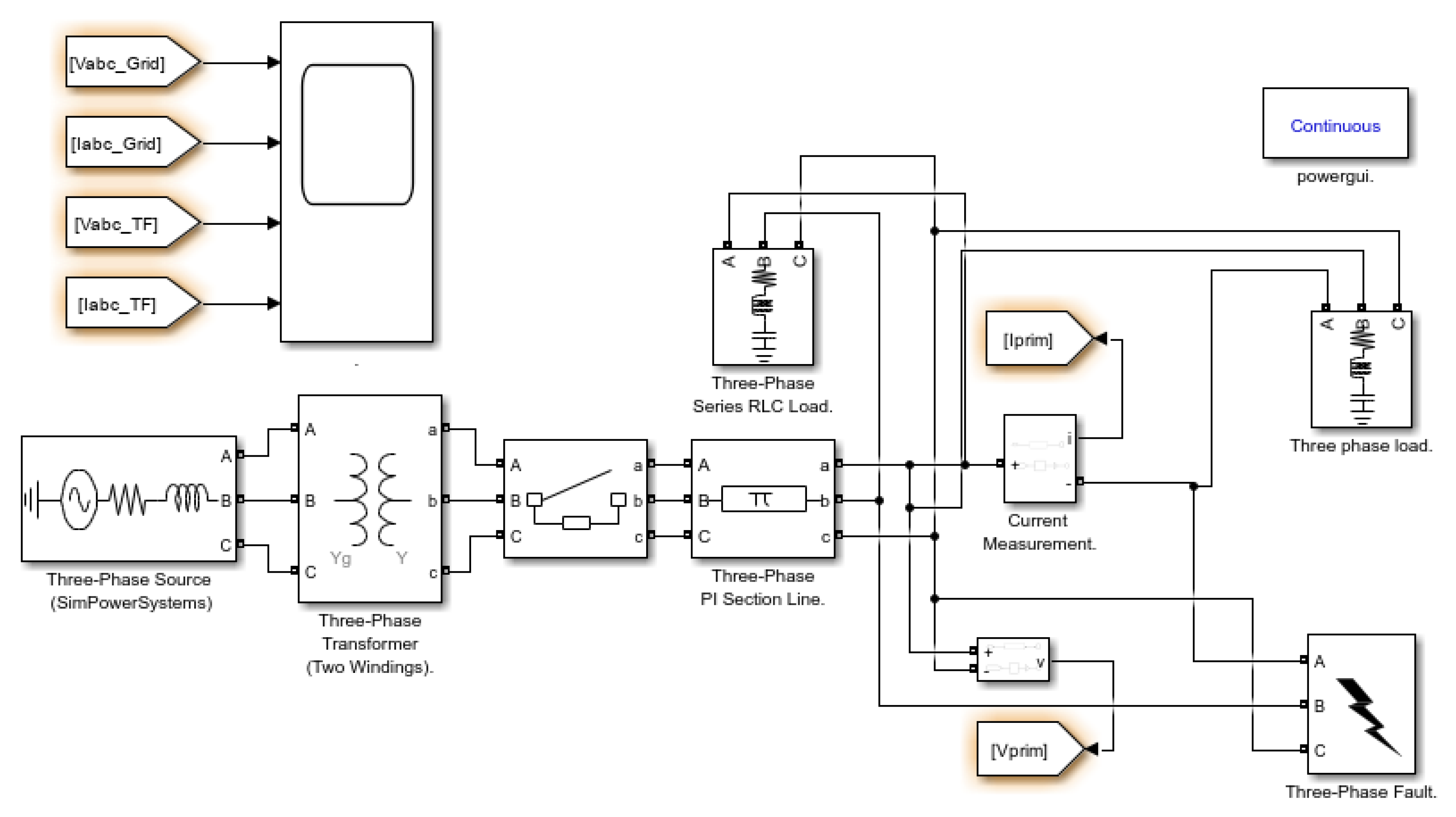
Figure 2.
Traditional block diagram of a DC microgrid architecture with offshore wind and solar farms connected through multi-terminal DC-DC converters.
Figure 2.
Traditional block diagram of a DC microgrid architecture with offshore wind and solar farms connected through multi-terminal DC-DC converters.
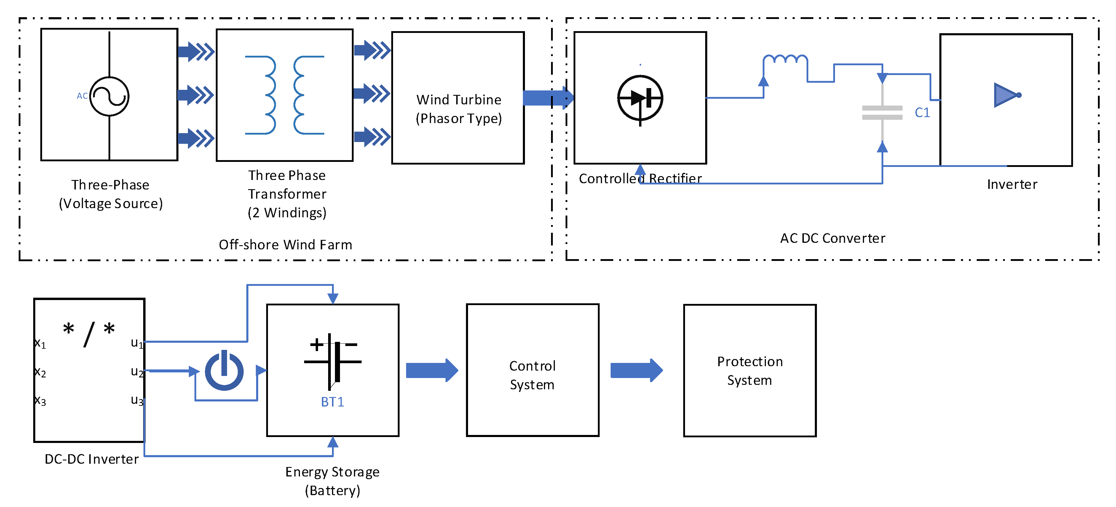
Figure 3.
The Model Predictive Control (MPC) to optimize the operation of the integrated offshore wind-solar microgrid, ensuring efficient power flow management and grid stability.
Figure 3.
The Model Predictive Control (MPC) to optimize the operation of the integrated offshore wind-solar microgrid, ensuring efficient power flow management and grid stability.
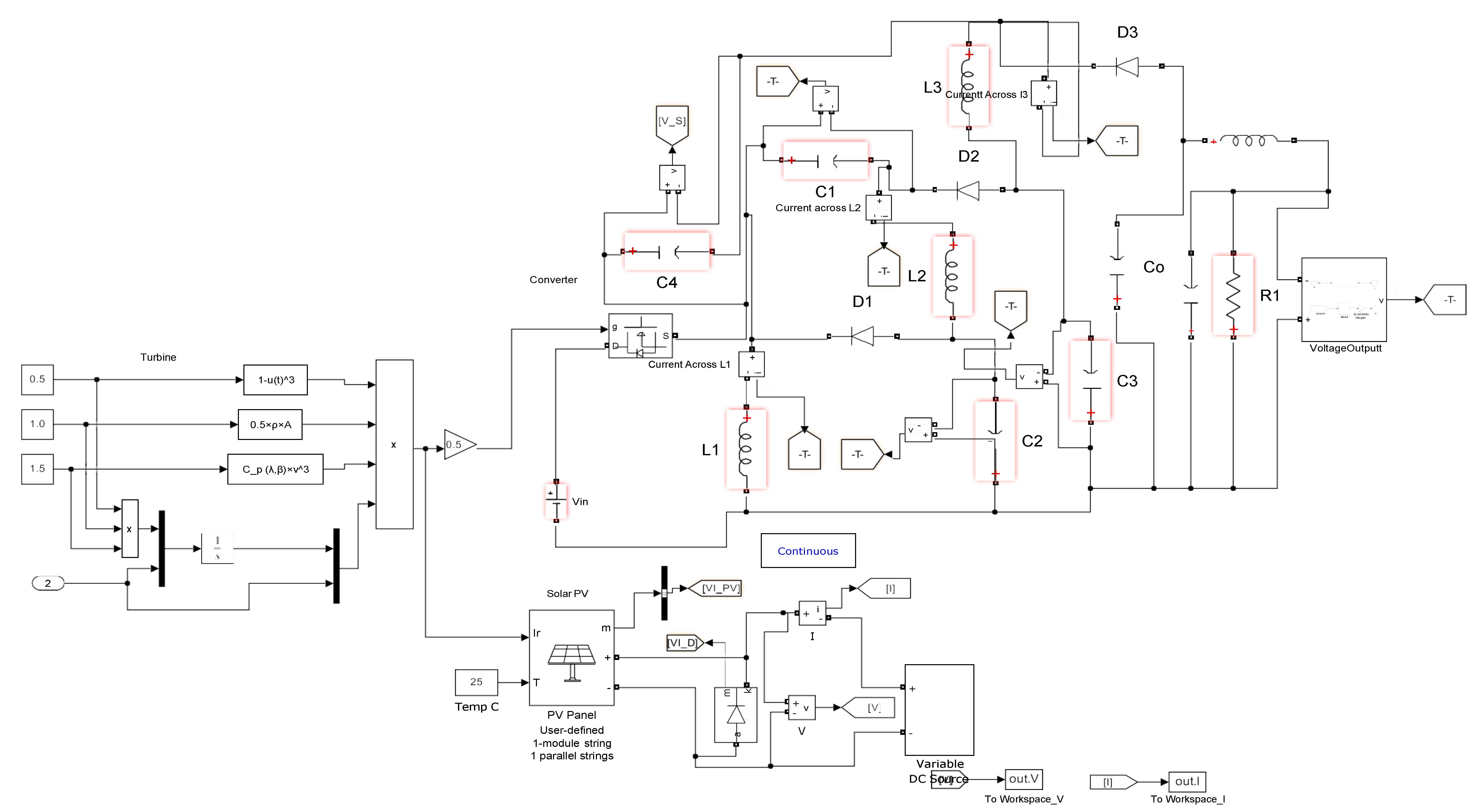
Figure 4.
Architecture of a proposed DC microgrid with multi-terminal DC-DC conversion.
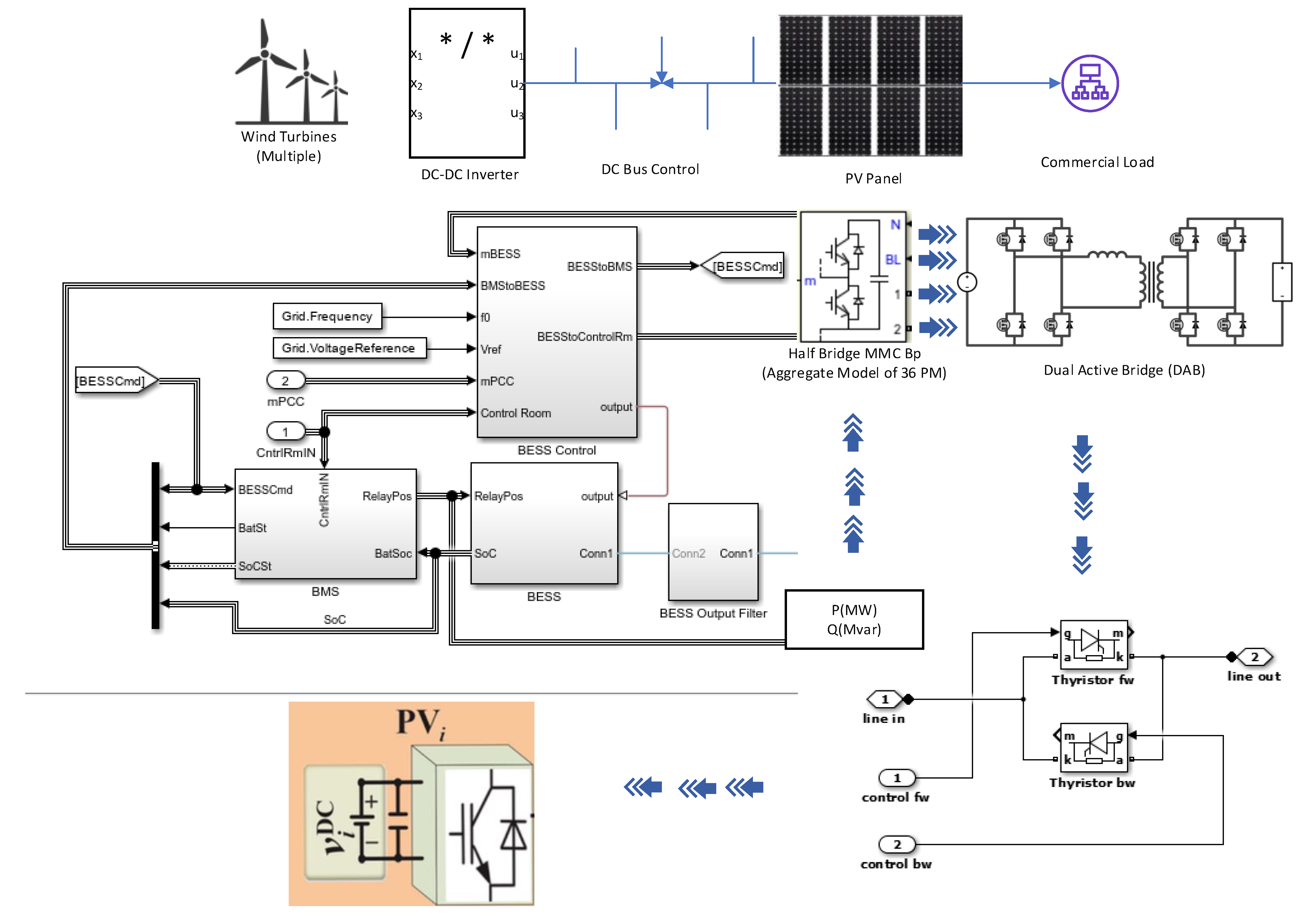
Figure 5.
profiles demonstrating the performance of the offshore wind-solar microgrid system (a) DC link voltage waveform (b) Load voltage waveform (c) Load power profile (d) Wind speed monitoring and (e) Solar irradiance pattern. Table 1 shows a comparative examination of the suggested approach in comparison with recent literature.
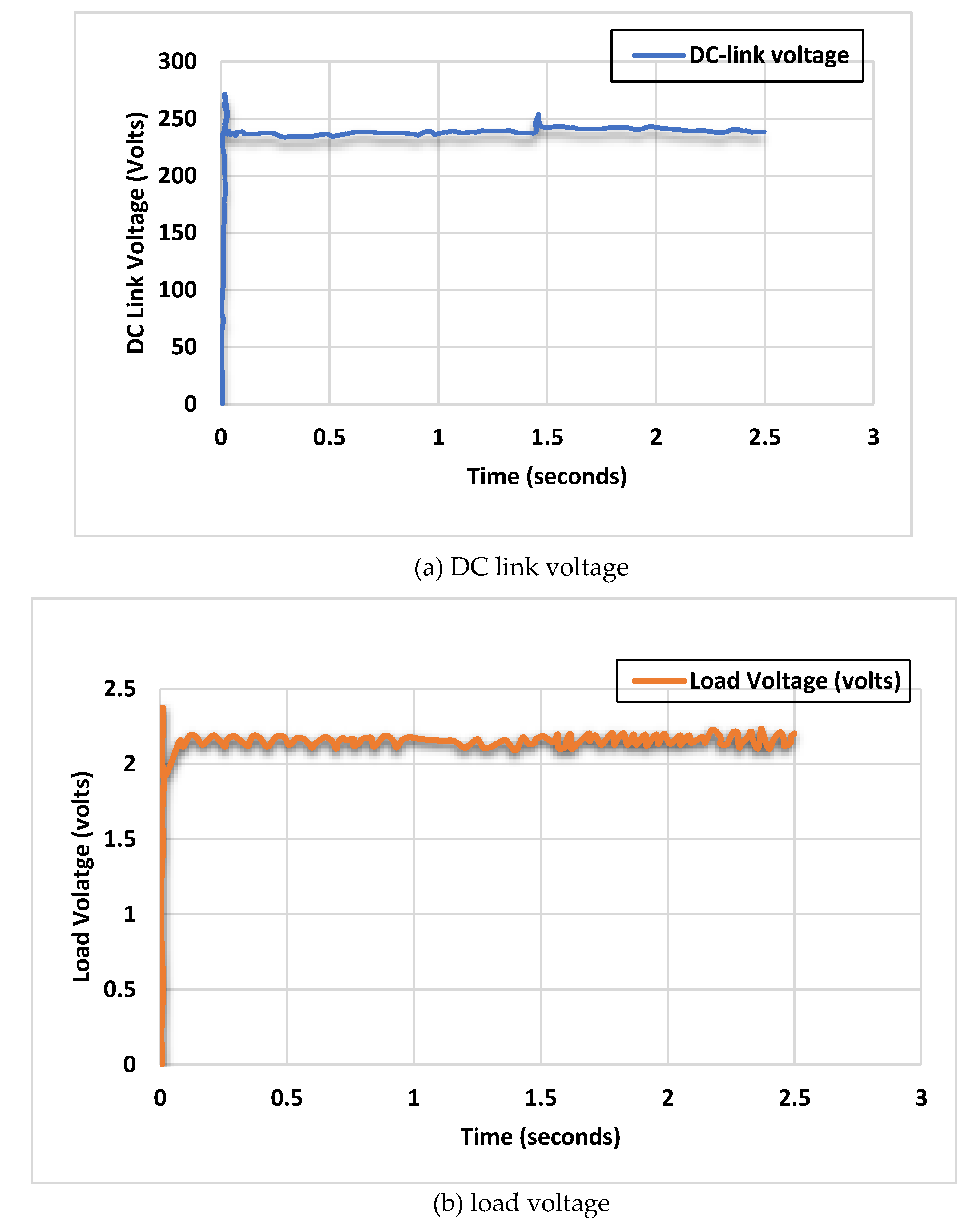
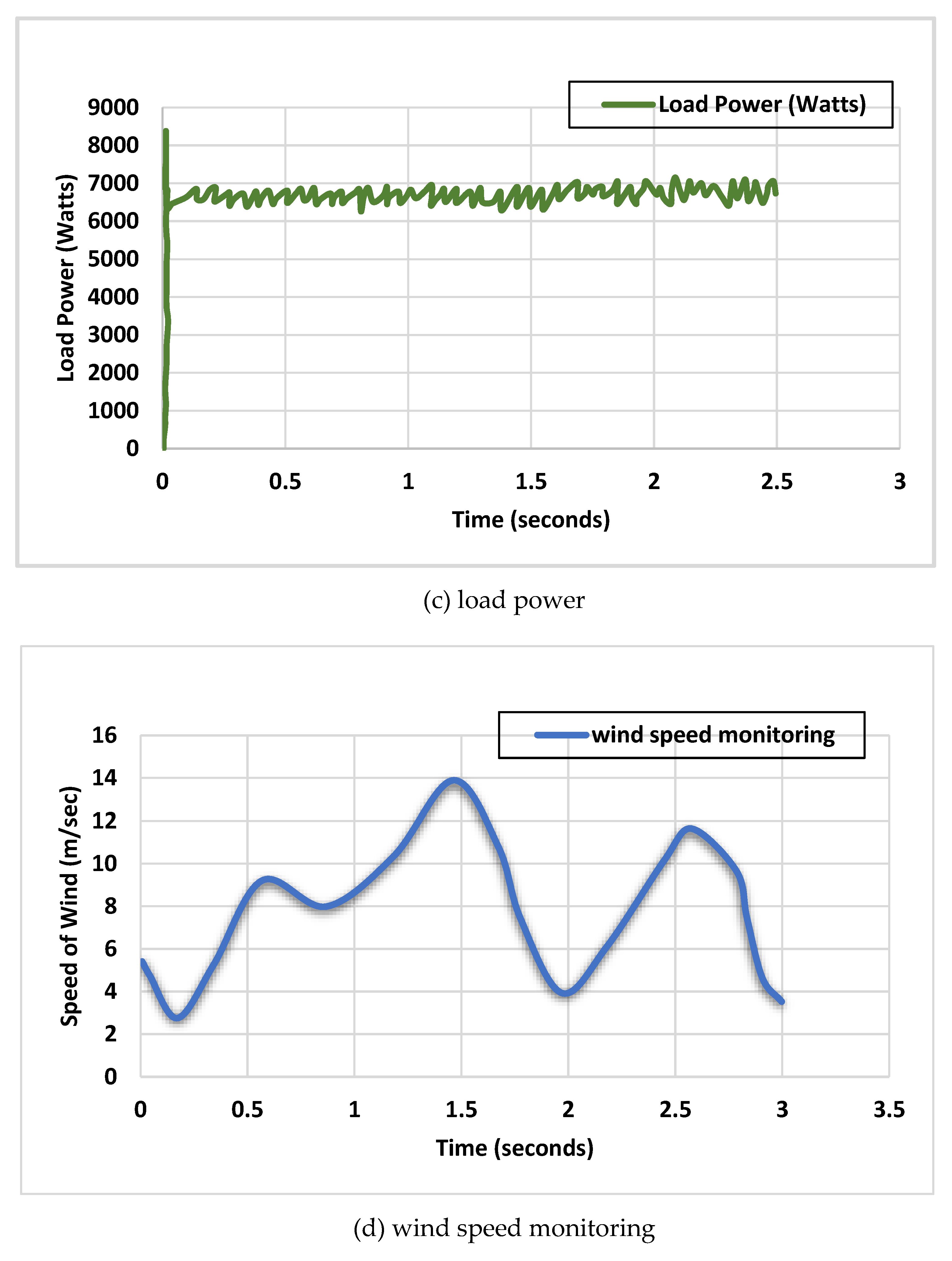
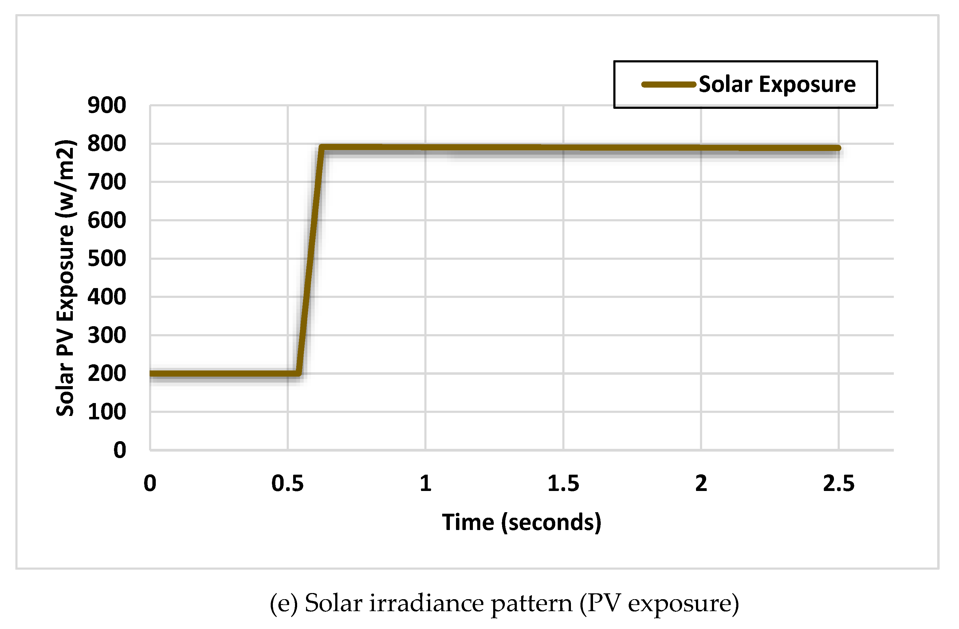
Figure 6.
Control and output waveforms of power electronic converters in the microgrid system. (a) Pulse-width modulation (PWM) switching cycle for converter control. (b) Voltage source inverter output waveform.
Figure 6.
Control and output waveforms of power electronic converters in the microgrid system. (a) Pulse-width modulation (PWM) switching cycle for converter control. (b) Voltage source inverter output waveform.
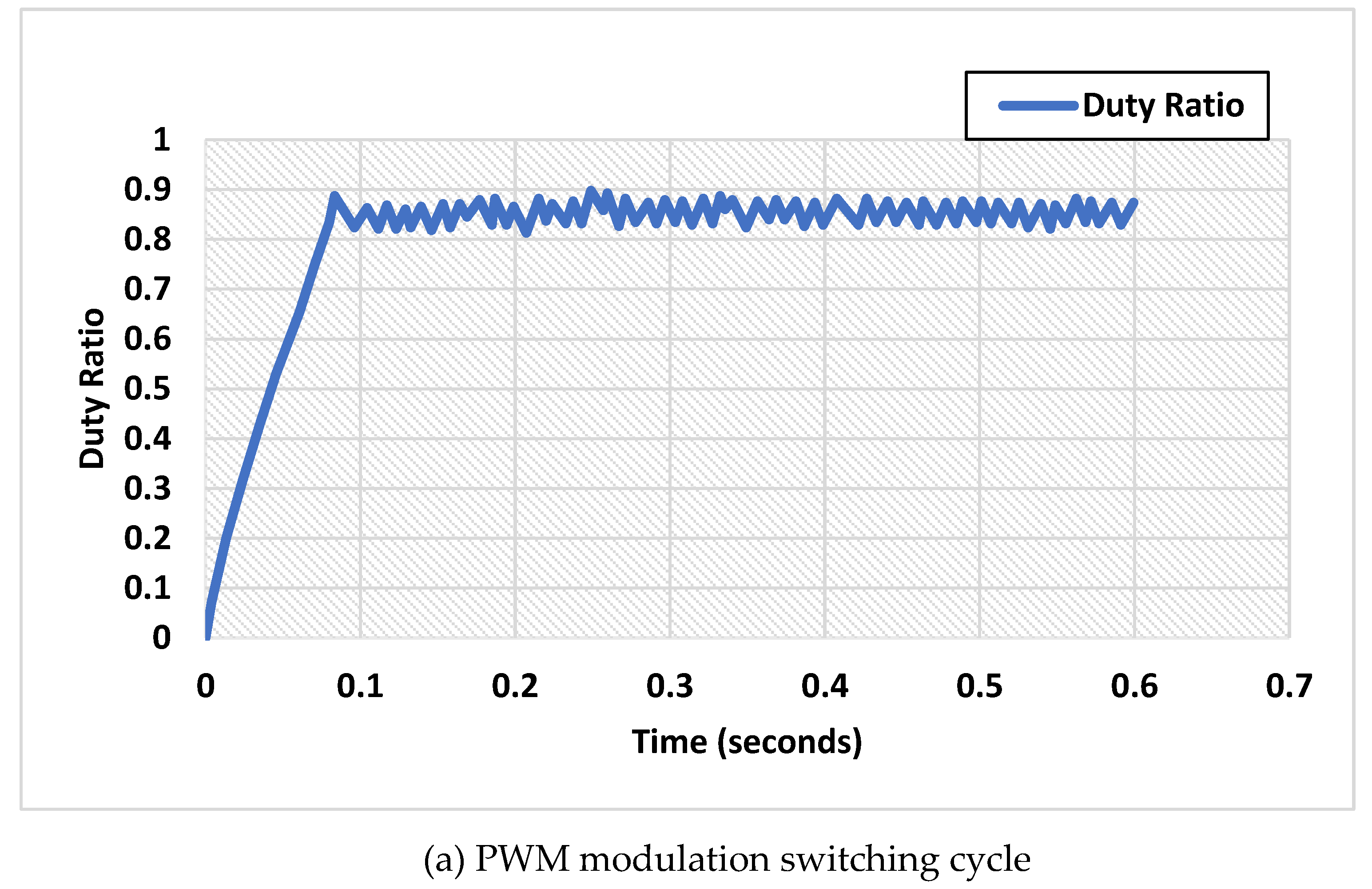
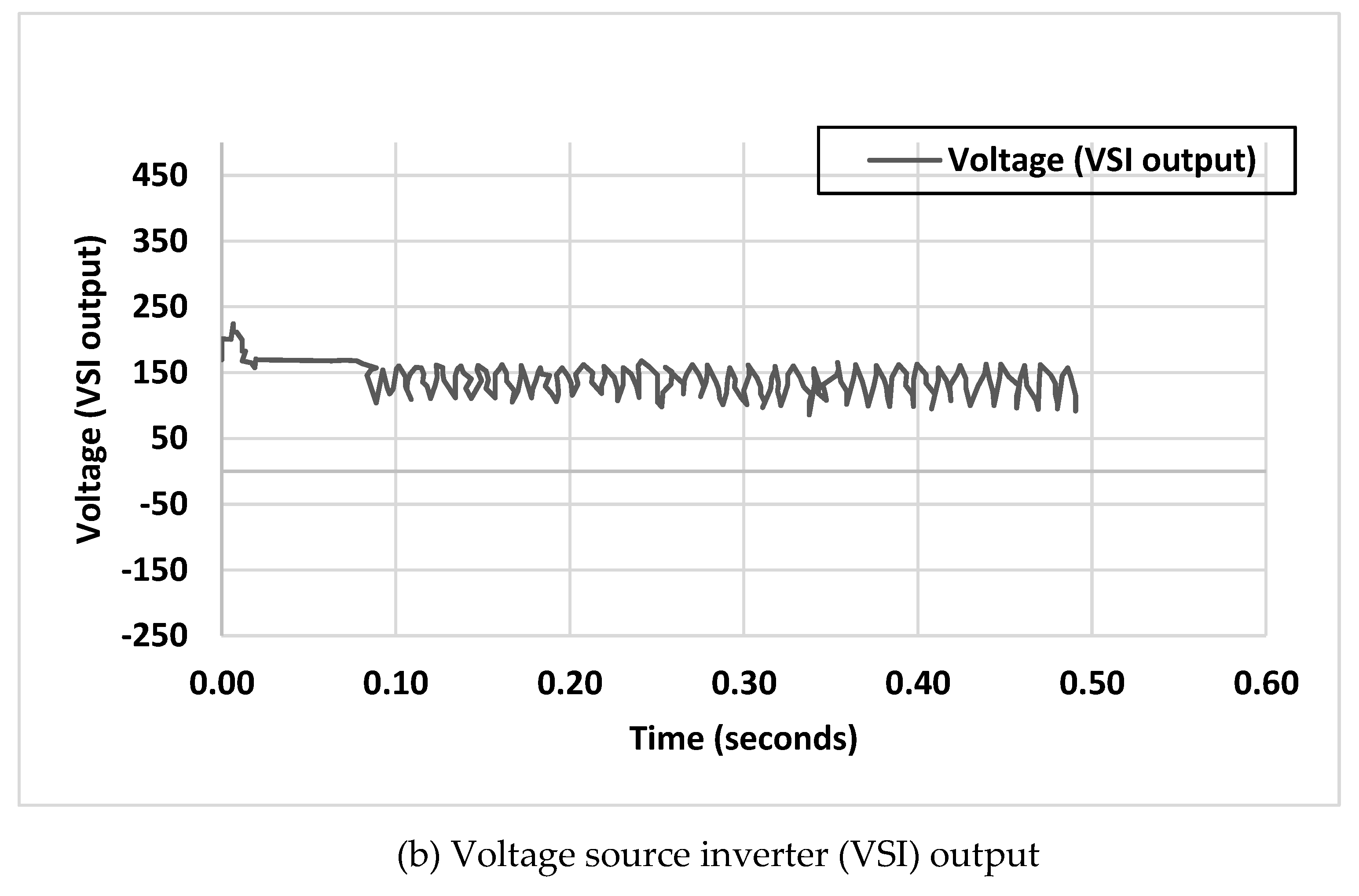

Table 1.
Comparative examination of the suggested approach in comparison with recent literature.
| Reference | This Work | [34] | [60] | [61] | [62] | [63] |
|---|---|---|---|---|---|---|
| Microgrid elements | Wind, solar PV, converter, load | Wind, PV, Converter, Load | PV, wind, BSS | PV, wind, BSS, SOFC load | PV, BSS, loads | PV, wind, BSS, load |
| Proposed Strategy | MPC-based hybrid conversion system integrating wind-dynamics with multi-terminal DC-DC control | Energy Management Control | Energy Management | Coordinated control | Energy Management | Energy Management, SSCs control |
| Main Contribution | AC-DC smart grid optimization and control of MPC | FLC and gain scheduling | Two low complexity LLCs | Two feedback control loops and feed forward control loop | Adaptive control | Super Twisting Fractional Order |
| Novelty behind proposed strategy |
|
|||||
Disclaimer/Publisher’s Note: The statements, opinions and data contained in all publications are solely those of the individual author(s) and contributor(s) and not of MDPI and/or the editor(s). MDPI and/or the editor(s) disclaim responsibility for any injury to people or property resulting from any ideas, methods, instructions or products referred to in the content. |
© 2024 by the authors. Licensee MDPI, Basel, Switzerland. This article is an open access article distributed under the terms and conditions of the Creative Commons Attribution (CC BY) license (http://creativecommons.org/licenses/by/4.0/).
Copyright: This open access article is published under a Creative Commons CC BY 4.0 license, which permit the free download, distribution, and reuse, provided that the author and preprint are cited in any reuse.


