
Submitted:
06 December 2024
Posted:
06 December 2024
You are already at the latest version
Abstract
In the cold chamber high pressure die casting process (CC-HPDC) for light alloys, the piston lubricants play a key role in protecting the piston tip from wearing and ensure adequate seal with the shot sleeve. However, during the production process, the pouring of overheated melt into the shot sleeve would lead to evaporation and burning of the lubricants once in contact with the piston tip. The burning products, however, would form gas and non-metallic inclusions in the melt which would be transported and injected into the die area and finally trapped in the castings, all of which would affect the mechanical properties of the as-cast samples and deteriorate the product quality. To further investigate this issue, a pilot scale HPDC machine is used and the lubricant burning issue is studied based on material characterization and numerical modelling. The chemical composition, size and morphology of the burned products are observed using scanning electron microscope and energy dispersive spectrometer. Based on this, a finite element model describing the entire HPDC process is established and the burning, motion, trapping of the lubricant are calculated. The final distribution of the burned products such as gas and non-metallic inclusions are predicted and their influence on final solidification quality of the as-cast products under various process parameters are analyzed qualitatively. Finally, the optimal process parameters such as piston shot profile, slow/fast shot speed are obtained to alleviate the burning of lubricant on final product quality.
Keywords:
High pressure die casting
; lubricant
; solidification
; mathematical modelling
; defects formation
1. Introduction
In the cold chamber high pressure die casting (CC-HPDC) process, commonly employed to produce light alloy components, piston lubricants are essential for ensuring smooth operation. The primary function of these lubricants is to protect the piston tip from wear and to guarantee an adequate seal between the piston and the shot sleeve. However, during the casting process, particularly when the molten metal is poured into the shot sleeve at high temperatures, a significant issue arises [1]. The overheated melt can cause the piston lubricant to evaporate and burn upon contact with the piston tip. The products of this combustion—comprising gas and non-metallic inclusions—become entrained in the melt, which is then injected into the die cavity. These contaminants can become trapped in the final casting, leading to various defects [2,3].
The formation of such defects, including gas porosity, oxide inclusions, and other non-metallic impurities, negatively impacts the mechanical properties of the as-cast products. These defects contribute to a reduction in the overall quality of the casting, influencing both the strength and durability of the final component [4]. Therefore, understanding the behavior of piston lubricants under high-temperature conditions and the subsequent effects on the melt flow and defect formation is crucial for optimizing the casting process and improving product quality [5,6].
Tsoukalas [7] studied the impact of die casting machine parameters for HPDC, including piston velocity, intensification pressure, and die cavity filling time, on the formation of porosity in cast components. He concluded that optimizing these parameters results in the minimum porosity in the final castings. Jiao [8] investigated the influence of slow-shot speed on primary silicon particles (PSPs) and porosity of AlSi17Cu2.5 alloy in high pressure die casting (HPDC). Fiorese [9] aimed at identifying the most relevant plunger kinematic parameters and estimates their correlation with the casting quality, by means of a statistically significant sample manufactured with different plunger motion profiles. Numerical simulations of the HPDC process are widely used, as both researchers and manufacturers aim to gain insights into aspects of the process that cannot be directly observed during real-world operations. Cleary [10] studied melt flow characteristics during HPDC and assessed the models accuracy by conducting interrupted filling tests during actual practice. Gerald [11] explored the optimization of the liquid jet exiting the ingate during HPDC by employing the smoothed particle hydrodynamics (SPH) method. Cica [12] created a predictive model for porosity of casting parts using fuzzy systems optimized by genetic algorithm and simulated annealing.
This study investigates the impact of lubricant combustion on the distribution of defects in CC-HPDC by employing a combination of material characterization, scanning electron microscopy (SEM), energy dispersive spectroscopy (EDS), and numerical modeling. By characterizing the chemical composition, size, and morphology of the combustion products, and simulating the complete HPDC process using finite element modeling (FEM), this research aims to provide a comprehensive understanding of the lubricant burning phenomenon and its influence on the final product quality. The study focuses on the formation of air entrainment, non-metallic inclusions, and the overall flow process, with the goal of identifying process parameters that minimize these defects.
2. Phenomenon Discovery and Experimental Methods
2.1. Phenomenon Discovery
Oil-based lubricants are commonly applied to the plunger tip in high-pressure die casting (HPDC) to prevent wear and seizure. These lubricants ensure smooth operation by forming a low-viscosity film at the interface between contacting surfaces. However, when molten metal enters the shot chamber, it reacts with the organic components of the lubricant, leading to pyrolysis that produces gaseous phases and carbonaceous residues, often visible as flames emerging from the pouring hole. These residues can become entrained in the molten metal during solidification, resulting in non-metallic inclusions in the final microstructure.
During HPDC experiments, we initially observed the presence of oxides, gas pockets, and inclusions in the cast samples. This issue arises because, during production, pouring overheated molten metal into the shot sleeve causes the lubricants to evaporate and combust upon contact with the piston tip. The combustion by-products generate gases and non-metallic inclusions within the melt, which are subsequently transported into the die cavity and trapped in the castings. These inclusions adversely affect the mechanical properties of the as-cast samples and significantly degrade product quality.
Figure 1 (a) shows a representative micrograph of an inclusion on the fracture surface of the tensile specimen, with large non-metallic inclusions observed within the pores. Oxides are also observed near to these inclusions. Pores are known to nucleate on non-wetted interfaces; favorable nuclei include the non-wetted surfaces of oxide films and certain non-metallic inclusions—particularly those comprising low-surface-tension liquids and non-wetted solids. A plausible explanation is that these inclusions, or the accompanying oxides, act as nuclei for the pores observed in these specimens. Previous research on the EDX analysis of fracture surfaces revealed that these inclusions typically contain elements such as C, Na, S, Cl, K, and Ca [13]. However, the presence of C alone, due to its low atomic mass, is insufficient to confirm the pyrolysis hypothesis, as C is a common contaminant in electron microscopy. Therefore, we focus on the heavier elements, namely Na, S, Cl, K, and Ca. Petrochemical or synthetic additives are often incorporated into lubricant base stocks to enhance their performance. Under severe mechanical or thermal loading, the lubricating film may rupture, causing direct asperity-asperity to contact on the metal surface. Extreme pressure (EP) additives, as their name suggests, improve lubrication under high-pressure conditions. These additives often contain compounds of S or Cl, which become reactive at elevated temperatures, releasing derivatives of S or Cl. These derivatives react with exposed metal surfaces to form protective compounds (e.g., FeS or FeCl₃), creating a thin solid layer that mitigates wear. Additionally, other additives such as surfactants and thickeners are common in commercial lubricants, often containing Na, K, and Ca compounds. To test the pyrolysis hypothesis, filling tests were conducted by allowing the liquid to solidify in the shot chamber while the piston remained stationary. Figure 1(b) shows a photograph of one of these filling test samples, with a close-up provided in Figure 1(c). In Figure 1(b), the location of the pouring hole is labeled as the "inlet," and during the experiment, the plunger was in contact with the left-hand surface of the billet. As depicted in Figure 1(c), large films are visible on the billet's surface, closely resembling the non-metallic inclusions shown in Figure 1(a). Based on these findings, it is plausible that the observed non-metallic inclusions result from the pyrolysis of commercial plunger lubricants. While one might argue that the identified elements could also originate from commercial foundry fluxes, no flux was used in these experiments.
2.2. HPDC Experiment
A pilot-scale high-pressure die casting (HPDC) machine was employed to address the issues of lubricant combustion and non-metallic inclusions identified in HPDC casting experiments. The combustion phenomena were analysed through material characterization and numerical simulation. The chemical composition, size, and morphology of combustion products in the castings were investigated using scanning electron microscopy (SEM) and energy dispersive spectroscopy (EDS). The alloy used in this study was Silafont-36 (Al-9Si-0.3Mg-0.5Mn). A 40 kg crucible of Silafont-36 was melted in an electric resistance furnace and held at 750°C for 30 minutes to ensure a uniform composition. The melt was then degassed using a high shear melt conditioning (HSMC) device [14], which consisted of two stages: (i) degassing for 10 minutes at a rotor speed of 1500 rpm and an argon flow rate of 0.2 L/min, followed by (ii) intensive melt shearing for 20 minutes without argon flow. Following melt treatment, the molten metal was transferred into the shot sleeve of a FRECH 4500 kN locking force cold chamber HPDC machine using a transfer ladle. The process parameters were controlled with the melt temperature maintained at 680°C, the shot sleeve at 180°C, and the die cavity at 150°C. The molten metal was injected into the die cavity at a slow shot speed of 0.3 m/s and a filling speed of 3.6 m/s to produce eight round tensile samples. These samples, with a nominal gauge diameter of 6.35 mm, were manufactured in accordance with ASTM standards. During experiments, different slow shot and filling speeds were selected to evaluate their influence on the casting process. The geometry of the tensile samples and gating system has been previously detailed in earlier studies [14].
2.3. Numerical Simulation Methods
A finite element model (FEM) was developed to simulate the entire HPDC process, accounting for lubricant combustion, movement, and entrapment. Using the ProCAST software platform, FEM mesh generation, model discretization, and result analysis were performed systematically. The final distribution of combustion products, such as gases and non-metallic inclusions, was predicted, and their effects on the solidification quality of as-cast products were qualitatively analyzed under various process parameters. The geometrical model of the HPDC system was created using CAD software (Figure 2(a)). To enhance computational efficiency, only half of the model was used for simulations.
Initially, the die temperature was set to room temperature (25°C). As the HPDC process began, heating channels located in the mobile and stationary dies were activated to raise the die temperature to the target working temperature of 180°C. Once the target temperature was reached, the heating channels were switched off. In the simulation, a dynamic heat boundary condition was applied to the dies based on the timing and sequence data, allowing the calculation of the die's temperature distribution. Air entrainment during HPDC, caused by turbulent flow and fluid atomization, was incorporated into the model using the GAS model (Péquet et al., 2002). The transport and accumulation of oxides were modeled using an oxide indicator, measured in units of cm²·s, which represents the free surface area multiplied by time. The calculated indicator values were transported with the fluid flow and free surface. The impact of intensification pressure on the solidification process was managed in the model through a critical gate solid fraction. Liquid feeding was assumed to cease when the solid fraction in the gate exceeded a critical threshold of 0.9, effectively controlling the solidification dynamics. In addition, round-mold and S-shape model were established in the same way for numerical simulation work and compared with experimental results in existing literature to verify the accuracy of the air entrainment model (Figure 2(b, c)). The specific model and results will be described in detail in Chapter 3.
3. Experimental Results and Model Validation
3.1. Electron Microscopy Observation of Casting Samples
To ensure that our findings are representative of industrial practices, fatigue specimens were machined from automotive components produced by HPDC. Various alloys were studied, sourced from different suppliers, and crack-initiating defects were identified through SEM fractography. Critical casting defects, including oxide films, porosity, and non-metallic inclusions, were observed, with a representative backscatter electron (BSE) micrograph shown in Figure 1(a). Although the Baseline process reflects typical industrial practices, automotive castings showed a higher prevalence of oxides compared to the Baseline samples. This is likely due to the increased geometric complexity of automotive components and the use of suboptimal melt handling procedures in commercial foundries, where controlling melt cleanliness is more challenging than in a controlled laboratory environment. Since the suppliers could not disclose their practices, the use of foundry flux during casting cannot be ruled out.
In all tensile samples with varying strengths, inclusions were detected (Figure 3). An enlargement of one of the tensile samples (Ultimate Tensile Strength, hereinafter as UTS: 278.4 MPa, Elongation, hereinafter as EL: 7.12%) revealed distinct oxide inclusions and shrinkage porosity. In the first tensile sample (Figure 4) (UTS: 275.4 MPa, EL: 6.38%), the elemental distribution at the surface of the thin oxide film was analyzed, with a more detailed examination focused on the region within the red box. Elemental analysis showed the presence of C, Al, O, Si, K, and Cu.
During the casting process, the metal is heated to over 600°C for a short period of time, during which the lubricant burns. Mixed with the liquid aluminum, the inclusions and gases are transported by the plunger through the gate into the casting, and after being pressed at high temperature, the gas eventually forms pinholes and porosity. At the same time, oxides are also carried into the casting.
3.2. Verification of Numerical Simulation Methods
To validate the accuracy of the simulated fluid flow patterns generated by the established model, two classical HPDC experimental results from Cao et al. (2018) and Homayonifar et al. (2008) were used as benchmarks. The comparisons between the experimental data and the simulation results are presented in Figure 5. These comparisons demonstrate that the mathematical model developed in this study accurately predicts the fluid flow behavior and air entrainment during the die-filling stage of the HPDC process.
4. Prediction of the Final Distribution of Combustion Products
4.1. The Motion Behavior of Oxides Generated by Lubricant Combustion During HPDC Process
In Figure 6, the oxides continuously rise to the surface during the slow shot phase. Additionally, due to the absence of a protective atmosphere as the piston advances, some of the melt surface is oxidized by air. These oxides accumulate on the melt surface, gradually forming a layer of oxide film. As the piston moves forward, the oxides accumulate at the front. During the melt injection phase, some of the oxides flow into the tensile sample area with the fluid, while most remain in the shot sleeve. Ultimately, the change in oxide concentration per unit area per unit time (i.e., diffusion rate) in the tensile sample region is approximately 6.0 cm²·s.
4.2. Influence of Slow Shot Velocity on Defects Formation
Building on the setup and validation of the aforementioned mathematical model, the pre-filling behavior and free surface evolution of the melt in the shot sleeve were modeled. The slow shot velocities were set at 0.2–0.3 m/s, 0.4–0.6 m/s, and 0.6–1.0 m/s, respectively. Figure 7, Figure 8 and Figure 9 illustrates the development of the shot wave and air entrapment during the shot sleeve filling process.
It is clear from the simulation results that during the slow shot phase (0.2–0.3 m/s) under baseline conditions, the melt flow is initiated by the movement of the piston, and the free surface remains relatively calm, with minimal air entrainment during both filling and injection (Figure 7). In the casting region, Air entrainment is not severe, with an overall low entrainment level primarily concentrated near the runner and gate areas. Only a slight amount of gas entrainment, approximately 0.01 g/cm³, is observed in the upper portion of one tensile sample. However, oxides are carried from the filling area into the casting region, with oxide inclusions mainly concentrated near the runner and mold cavity entrance, showing relatively high values. Some tensile samples exhibit severe oxide inclusions, approximately 4.8–6.9 cm²·s. Under low-speed conditions, the metal flow remains relatively stable, but the extended exposure time of the liquid metal surface increases the likelihood of oxide formation.
When the piston slow shot velocity is increased to 0.4–0.6 m/s, a wave forms at the free surface front, though air entrainment remains minimal (Figure 8). The air entrainment in the casting region is slightly more severe compared to the 0.2–0.3 m/s condition, but it remains relatively acceptable, with entrainment observed only in certain areas of the tensile samples. The increased velocity accelerates the flow of the molten metal, leading to greater air entrapment, though the higher speed may also cause localized breaking of entrained air pockets. In contrast, the oxide inclusion condition is improved, with a relatively stable distribution across the casting region, averaging around 4.3 cm²·s. The medium-speed flow reduces surface exposure time and minimizes the breakage and entrainment of oxide films, though some localized inclusions are still present.
Further analysis of the melt flow was conducted by increasing the piston velocity to 0.6–1.0 m/s (Figure 9). In this case, as the piston accelerates, the melt's free surface accumulates and contacts the top of the chamber before collapsing. During this phase, a portion of the air is captured at the fluid front, which is subsequently transported into the die cavity and remains in the final casting. The air entrainment within the casting is more evenly distributed but has a noticeably higher density compared to the two lower-speed conditions. This is because the higher flow velocity increases air entrainment, and the faster speed disperses the entrained air throughout the casting. Oxide inclusions also increase significantly, particularly within the runner and casting regions, with red zones indicating areas of high oxide concentration. The high-speed jet intensifies turbulence in the metal flow, making surface oxides more likely to be drawn into the molten metal, leading to a greater amount of oxide inclusions.
From these comparisons, it can be concluded that to minimize air entrainment, the piston velocity during the slow shot phase should not exceed 0.6 m/s. Additionally, lower slow shot velocities result in more severe oxide inclusions.
4.3. Motion and Distribution of Particles of Different Sizes
The particle trajectory distribution map was plotted (Figure 10), and it can be observed that finer particles travel further along the flow field, resulting in a broader distribution. In contrast, larger particles only travel shorter distances, leading to a more localized distribution. The larger particles (100 microns) show relatively smooth and stable trajectories in the tensile sample region. This stability minimizes the potential for turbulence-induced defects and ensures uniform filling of the tensile sample. However, due to their larger size and higher inertia, these particles may not adapt well to sudden changes in flow direction, potentially leading to poor flow in complex geometries or insufficient filling in intricate areas. The smaller particle size (20 microns) allows for greater adaptability to the flow dynamics, potentially enabling better filling of complex geometries within the tensile sample. Bur increased dispersion and irregular trajectories may introduce turbulence, leading to flow instabilities and potential defects such as air entrapment or non-uniform microstructure. 15-micron particles are highly responsive to flow, enabling them to reach finer details in the tensile sample region. This property is advantageous for ensuring complete filling of intricate areas. However, highly chaotic and dispersed trajectories make the flow pattern unpredictable, increasing the likelihood of turbulence and associated defects, such as porosity or oxide entrapment, which could compromise the mechanical properties of the tensile sample.
4.4. Influence of Piston Slow Shot Acceleration on Defects Formation
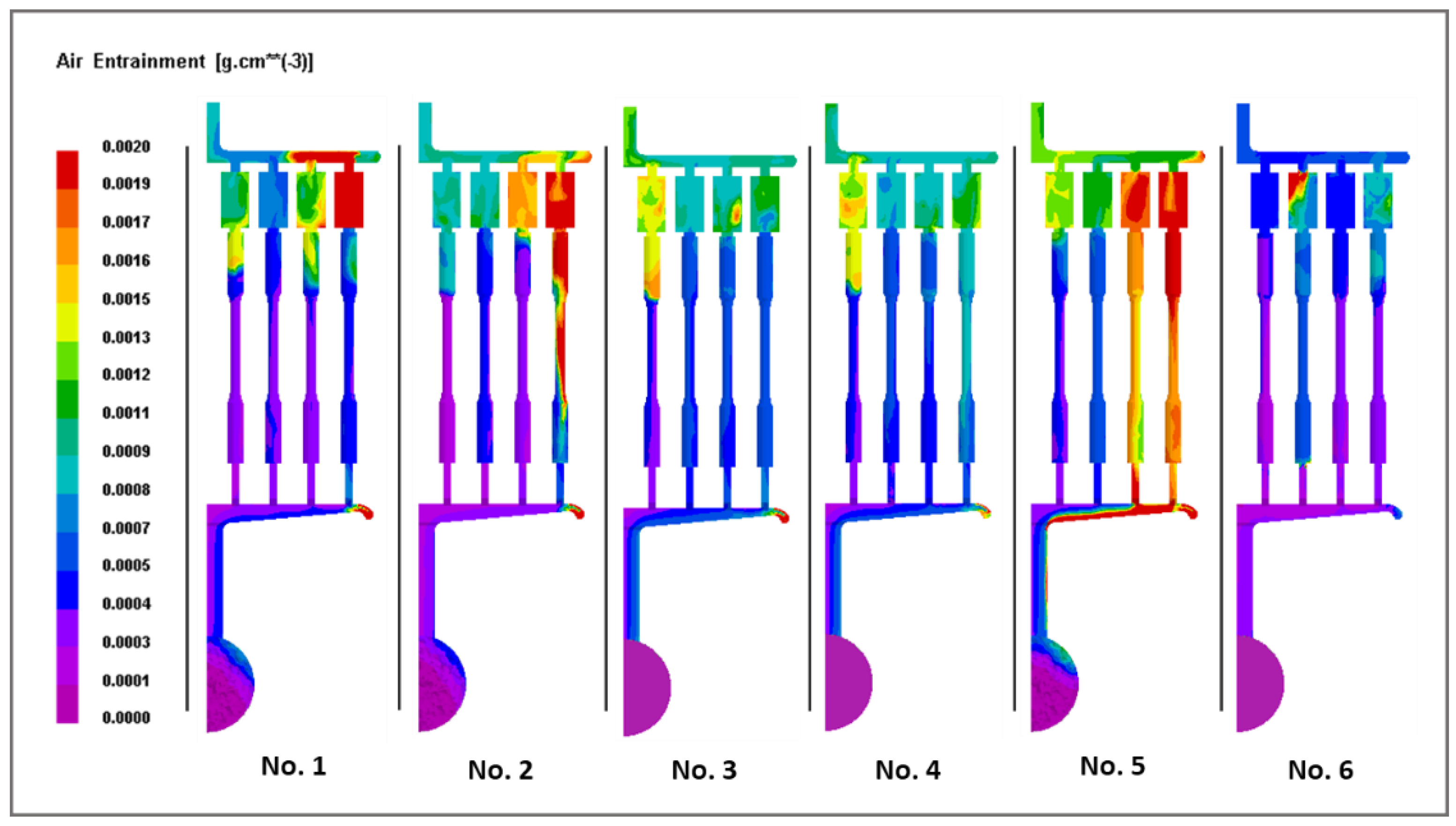
HPDC simulation experiments were conducted using six different slow shot acceleration profiles, which are as follows: acceleration from 0 to 0.2 m/s within 10 mm, 30 mm, 50 mm, and 60 mm, acceleration from 0 to 0.3 m/s within 50 mm, and acceleration from 0 to 0.3 m/s within 370 mm (Figure 11). The relationship between position and velocity for each slow-shot acceleration profile was plotted (Figure 12). The segment from 0 to 370 mm represents the slow-shot phase, while the range from 405 to 450 mm corresponds to the rapid injection phase. The results of gas entrainment were subsequently obtained.
From Figure 13, it can be observed that conditions 1, 2, and 5 exhibit relatively severe air entrainment, with some areas reaching the red level (i.e., air entrainment greater than 0.002 g/cm³). Additionally, for conditions 2 and 5, the tensile samples in certain regions show significant air entrainment, which could severely affect the tensile properties of the castings. Conditions 3 and 4 have similar levels of air entrainment, with some entrainment present, but the distribution is relatively uniform, and the levels are not as high. The optimal condition is found to be condition 6, where the air entrainment in the casting area is minimal, with many regions showing no entrainment at all. Castings produced under this condition should exhibit the best performance and fewer defects.
4.4. Optimal Process Parameters to Reduce the Combustion of Lubricants on the Final Product Quality
To achieve better final sample quality, it is essential to select the most suitable process parameters, primarily including slow-shot velocity and slow-shot acceleration profiles. Based on the results of the completed numerical simulations, the following observations were made. Low velocity (0.2–0.3 m/s): This condition results in less air entrainment but higher oxide inclusions, making it suitable for castings with high surface quality requirements. Medium velocity (0.4–0.6 m/s): Air entrainment and oxide inclusions are relatively balanced in this range, making it the most optimized velocity range for castings with comprehensive performance requirements. High velocity (0.6–1.0 m/s): Air entrainment significantly increases, and oxide inclusions also become more prevalent. This condition is suitable for producing castings where internal porosity and inclusions are less critical. For general cases, the optimal slow-shot velocity is found to be in the range of 0.4–0.6 m/s. Regarding the slow shot acceleration profile, the most favourable casting performance corresponds to condition 6, where the slow shot velocity accelerates from 0 to 0.3 m/s over 0-370 mm during the slow-shot phase. This optimized method can be applied to various high-pressure die casting processes, regardless of the specific casting size or design. To achieve the best process parameters, simulations can be conducted to assess the impact of lubricant combustion, oxide inclusions, and air entrainment, followed by adjustments to minimize negative effects.
5. Conclusions
This study presents a detailed analysis of the impact of piston lubricant combustion on defect formation in the cold chamber high-pressure die casting process. The results reveal that the combustion of piston lubricants leads to the generation of gas bubbles and non-metallic inclusions, which are transported into the die cavity and subsequently trapped in the castings. These defects significantly influence the mechanical properties of the final product, primarily through the formation of porosity and oxide inclusions.
By using material characterization techniques such as SEM and EDS, as well as numerical simulations based on finite element modeling, we have been able to predict the distribution of these defects under various process parameters. The simulations also provided insight into the effect of different slow shot velocities and acceleration profiles on defect formation. Based on the findings, the optimal process parameters for minimizing the impact of lubricant combustion on product quality were identified. Specifically, a slow shot velocity range of 0.4–0.6 m/s and an acceleration profile that ramps up to 0.3 m/s over 0–370 mm of the shot sleeve proved to be the most effective in reducing air entrainment and oxide inclusions.
This research provides valuable insights into the complex interactions between piston lubricants, melt flow, and defect formation in HPDC. The optimized process parameters identified in this study offer a practical solution for improving the quality of castings, particularly in industries where surface finish and mechanical integrity are of utmost importance. Future work will focus on further refining these process parameters and exploring the use of advanced lubricant formulations to further mitigate the negative effects of combustion during the casting process.
Author Contributions
Conceptualization, K. D.; methodology, K. D.; software, K. D.; validation, K. D., E. L. and Z. F.; formal analysis, Z. F.; investigation, J. L.; resources, K. D.; data curation, Y. Z.; writing—original draft preparation, J. L.; writing—review and editing, K. D.; visualization, J. L.; supervision, K. D., E. L. and Z. F.; W. W.; project administration, K. D.; funding acquisition, Z. F.; W. W. All authors have read and agreed to the published version of the manuscript.
Funding
This research was funded by the National Science Foundation of China (52304360) and the Open foundation of the State Key Laboratory of Advanced Metallurgy, University of Science and Technology Beijing, China (K22-07), the Key Research and Development Program of Xiangjiang Laboratory (22XJ01002) and Engineering and Physical Sciences Research Council (EPSRC) and Jaguar Land Rover Ltd. [grant number 11055100].
Informed Consent Statement
Informed consent was obtained from all subjects involved in the study.
Data Availability Statement
The original contributions presented in the study are included in the article/supplementary material, further inquiries can be directed to the corresponding author/s.
Acknowledgments
This work was supported by the National Science Foundation of China (52304360) and the Open foundation of the State Key Laboratory of Advanced Metallurgy, University of Science and Technology Beijing, China (K22-07), the Key Research and Development Program of Xiangjiang Laboratory (22XJ01002) and Engineering and Physical Sciences Research Council (EPSRC) and Jaguar Land Rover Ltd. [grant number 11055100].
Conflicts of Interest
The authors declare no conflicts of interest.
References
- Wang, S.; Wang, Y.; Ramasse, Q.; Fan, Z. The Nature of Native MgO in Mg and Its Alloys. Metallurgical and Materials Transactions A 2020, 51, 2957–2974. [CrossRef]
- Lebon, G.S.B.; Li, H.-T.; Patel, J.B.; Assadi, H.; Fan, Z. Numerical Modelling of Melt-Conditioned Direct-Chill Casting. Applied Mathematical Modelling 2020, 77, 1310–1330. [CrossRef]
- Tian, C.; Law, J.; van der Touw, J.; Murray, M.; Yao, J.-Y.; Graham, D.; St. John, D. Effect of Melt Cleanliness on the Formation of Porosity Defects in Automotive Aluminium High Pressure Die Castings. Journal of Materials Processing Technology 2002, 122, 82–93. [CrossRef]
- Wu, M.; Li, X.; Guo, Z.; Xiong, S. Effects of Process Parameters on Morphology and Distribution of Externally Solidified Crystals in Microstructure of Magnesium Alloy Die Castings. China Foundry 2018, 15, 139–144. [CrossRef]
- Zhang, Y.; Patel, J.B.; Lazaro-Nebreda, J.; Fan, Z. Improved Defect Control and Mechanical Property Variation in High-Pressure Die Casting of A380 Alloy by High Shear Melt Conditioning. JOM 2018, 70, 2726–2730. [CrossRef]
- Gourlay, C.M.; Laukli, H.I.; Dahle, A.K. Defect Band Characteristics in Mg-Al and Al-Si High-Pressure Die Castings. Metallurgical and Materials Transactions A 2007, 38, 1833–1844. [CrossRef]
- Tsoukalas, V. The Effect of Die Casting Machine Parameters on Porosity of Aluminium Die Castings. International Journal of Cast Metals Research 15, 581–588. [CrossRef]
- Jiao, X.Y.; Wang, J.; Liu, C.; Guo, Z.; Wang, J.; Wang, Z.; Gao, J.; Xiong, S.M. Influence of Slow-Shot Speed on PSPs and Porosity of AlSi17Cu2.5 Alloy during High Pressure Die Casting. Journal of Materials Processing Technology 2019, 268, 63–69. [CrossRef]
- Fiorese, E.; Bonollo, F. Plunger Kinematic Parameters Affecting Quality of High-Pressure Die-Cast Aluminum Alloys. Metallurgical and Materials Transactions A 2016, 47, 3731–3743. [CrossRef]
- Cleary, P.W.; Ha, J.; Prakash, M.; Nguyen, T. Short Shots and Industrial Case Studies: Understanding Fluid Flow and Solidification in High Pressure Die Casting. Applied Mathematical Modelling 2010, 34, 2018–2033. [CrossRef]
- Pereira, G.G.; Cleary, P.W.; Serizawa, Y. Prediction of Fluid Flow through and Jet Formation from a High Pressure Nozzle Using Smoothed Particle Hydrodynamics. Chemical Engineering Science 2018, 178, 12–26. [CrossRef]
- Cica, D.; Kramar, D. Intelligent Process Modeling and Optimization of Porosity Formation in High-Pressure Die Casting. International Journal of Metalcasting 2018, 12, 814–824. [CrossRef]
- Lordan, E.; Dou, K.; Zhang, Y.; Tzileroglou, C.; Jacot, A.; Blake, P.; Fan, Z. Turbulent Breakup of Non-Metallic Inclusions and Equiaxed Crystals during Solidification of a Hypoeutectic Al-Si Alloy. Materialia 2021, 17, 101114. [CrossRef]
- Zhang, Y.; Lordan, E.; Dou, K.; Wang, S.; Fan, Z. Influence of Porosity Characteristics on the Variability in Mechanical Properties of High Pressure Die Casting (HPDC) AlSi7MgMn Alloys. Journal of Manufacturing Processes 2020, 56, 500–509. [CrossRef]
Figure 1.
Source of non-metallic inclusions. (a) Micrograph showing a representative non-metallic inclusion observed on the fracture surface of a fatigue specimen extracted from an automotive component. (b) Image of a shot chamber filling test sample, with the inlet corresponding to the pouring hole. (c) Enlarged view of the dashed region highlighted in (b).
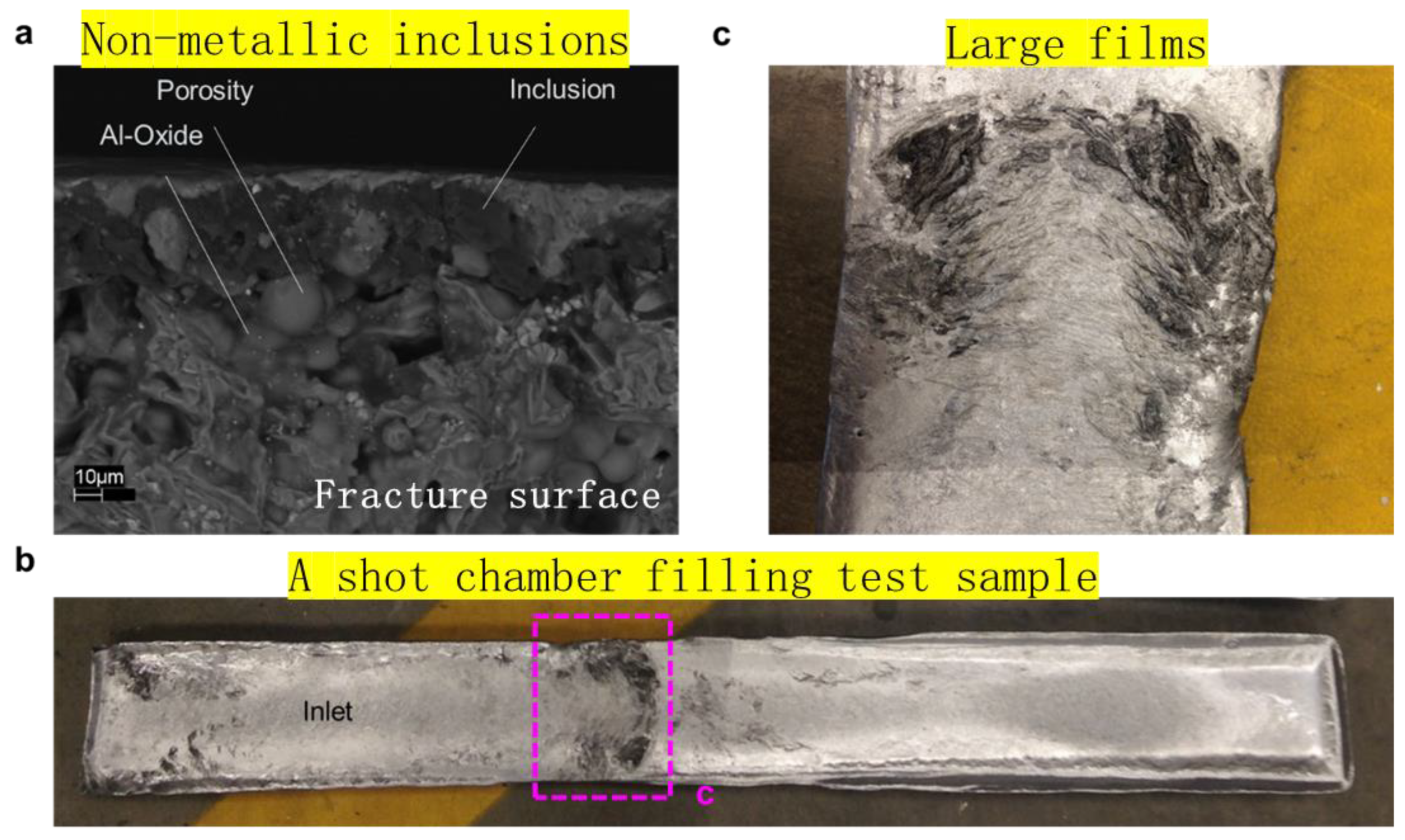
Figure 2.
FEM models (a) HPDC system model. (b) Round-mold model. (c) S-shape model.
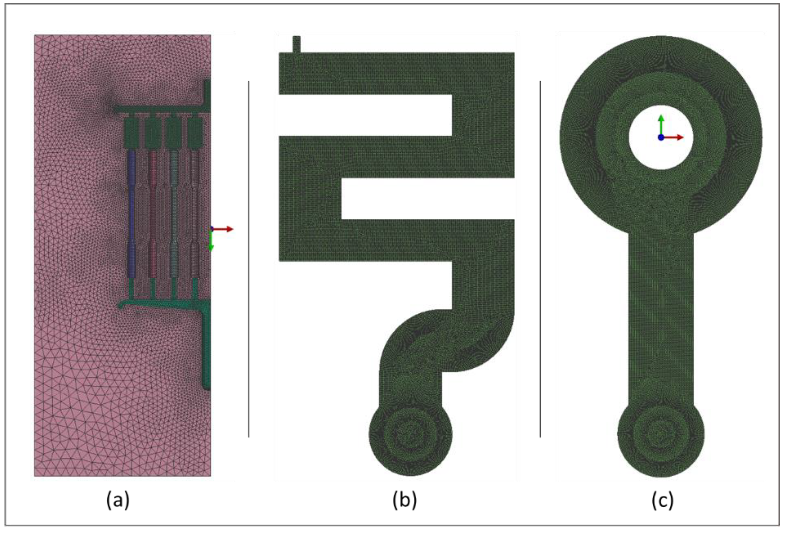
Figure 3.
Observation of fracture surfaces of tensile samples with different strengths.
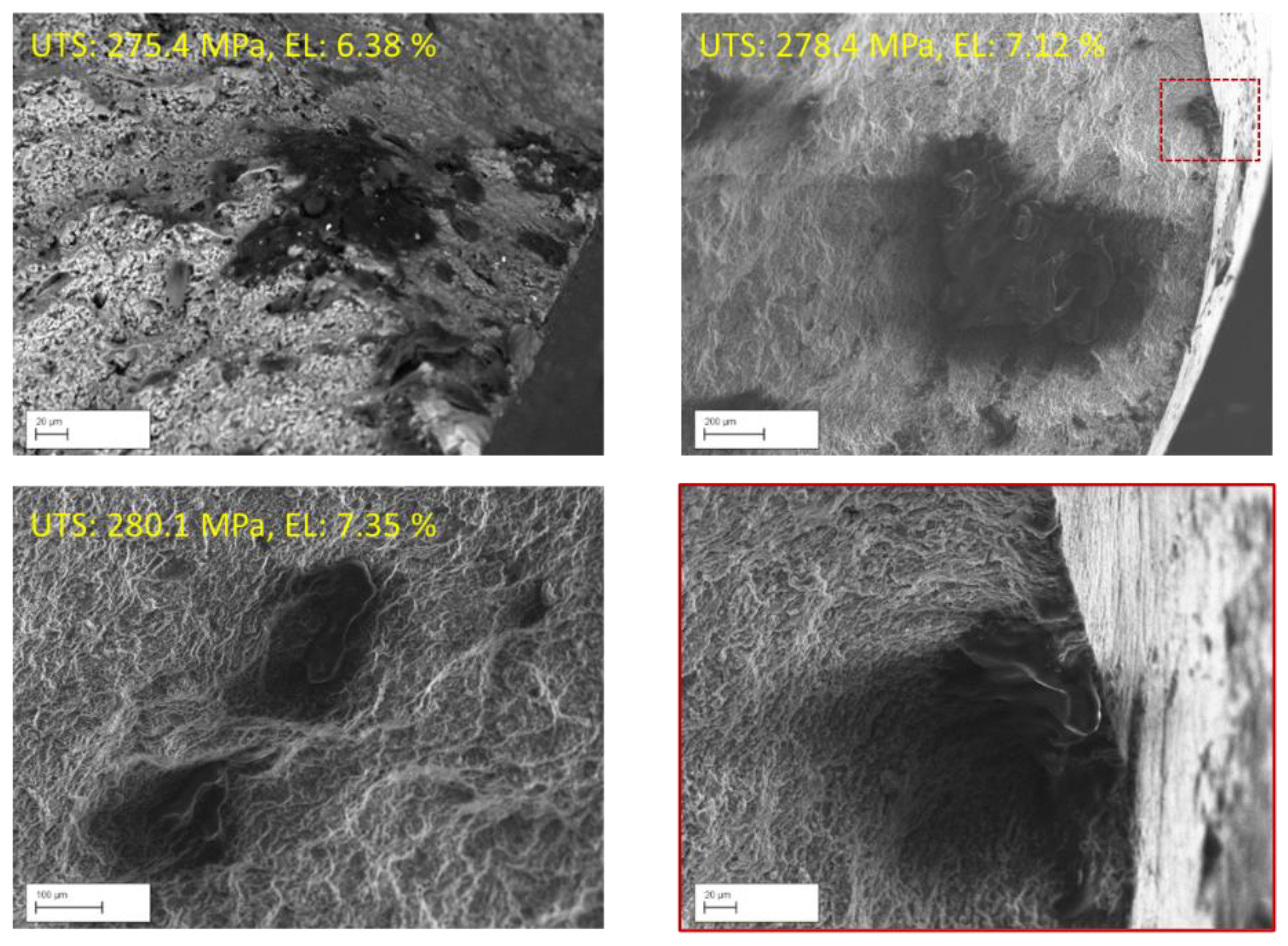
Figure 4.
EDS results of tensile sample fracture surface.
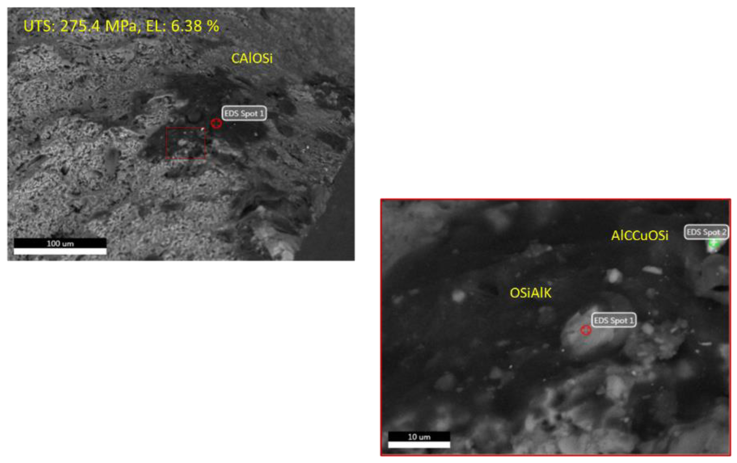
Figure 5.
Round-mold model and S-shape model validation.
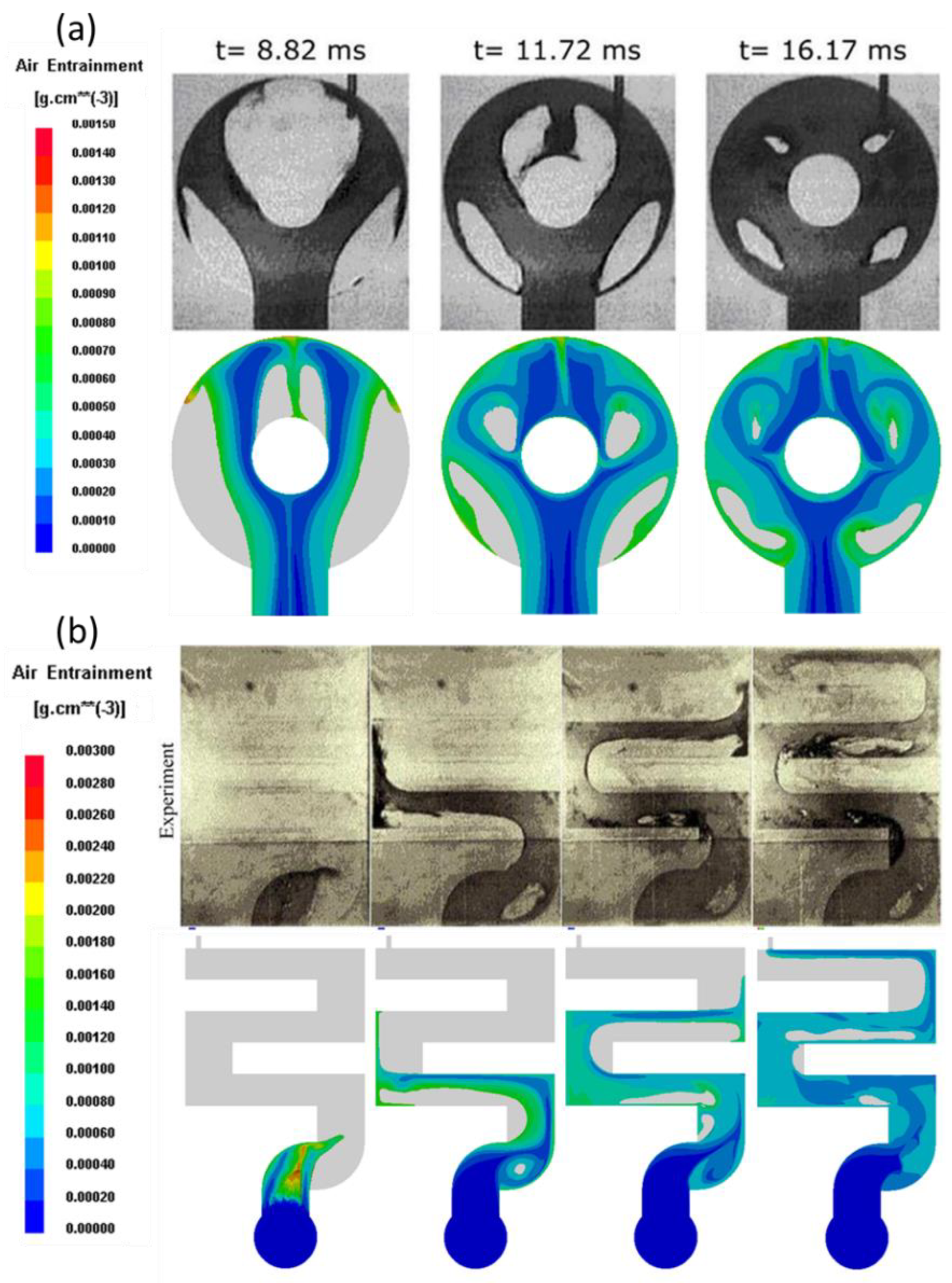
Figure 6.
Distribution of oxides during die-casting process.
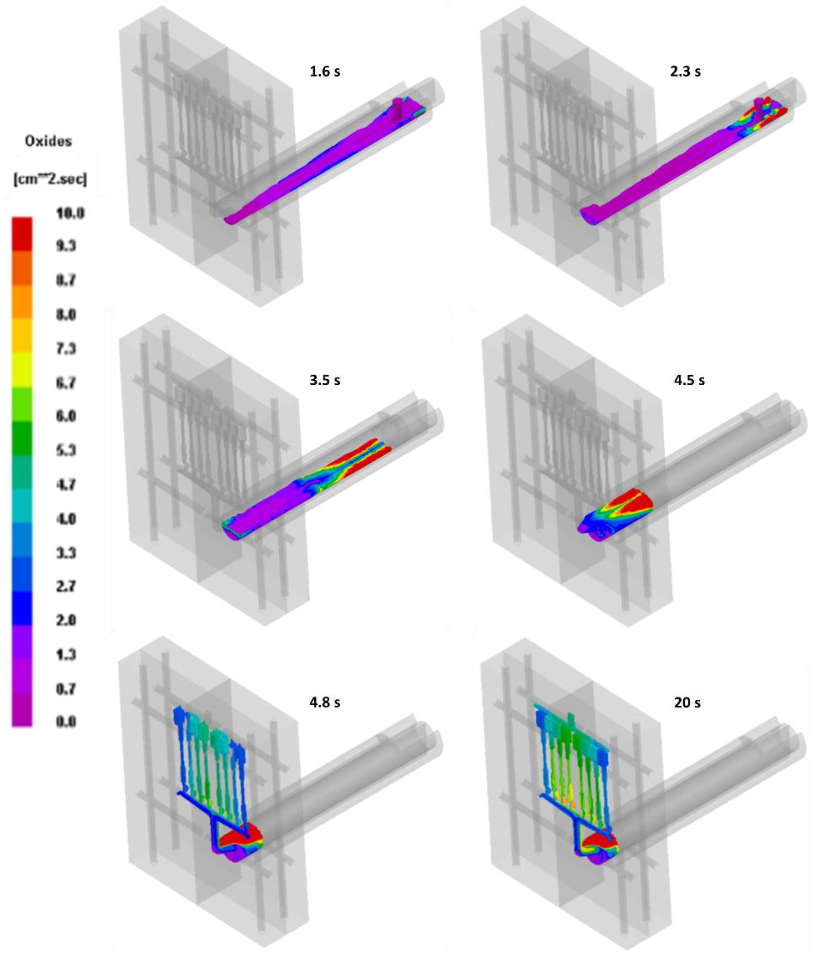
Figure 7.
Air entrapment in casting samples at a slow shot velocity of 0.2-0.3 m/s.
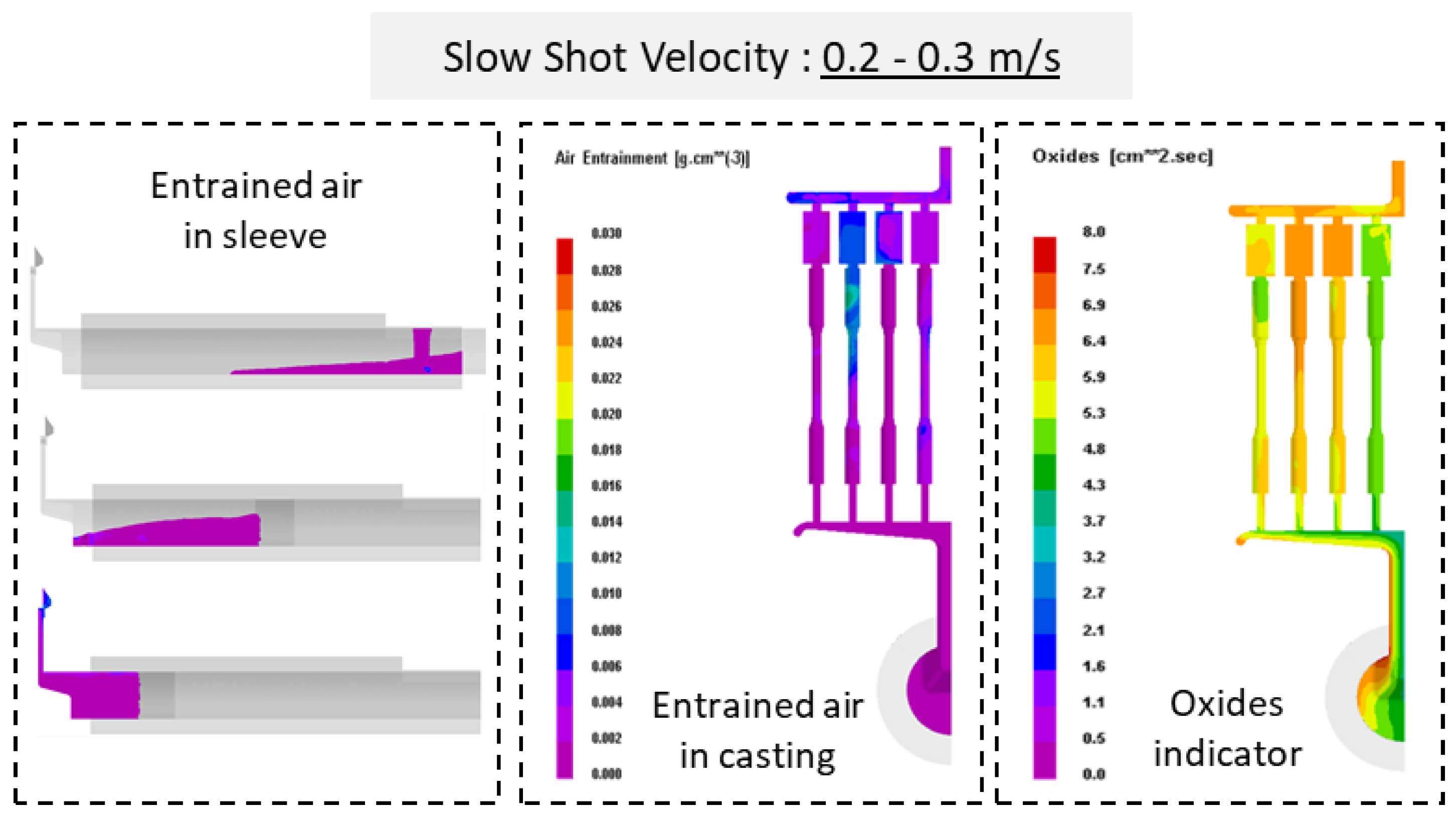
Figure 8.
Air entrapment in casting samples at a slow shot velocity of 0.4-0.6 m/s.
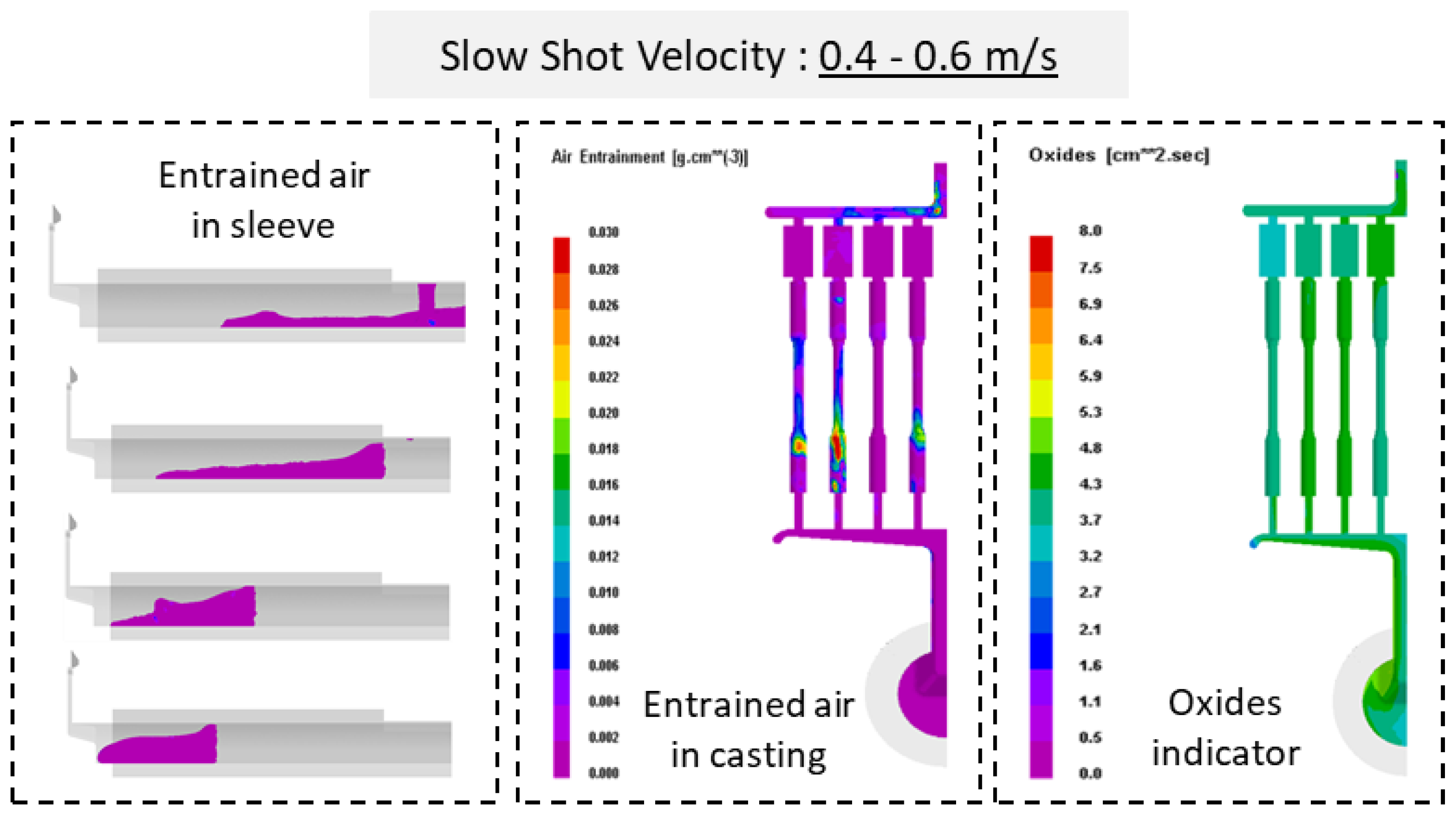
Figure 9.
Air entrapment in casting samples at a slow shot velocity of 0.6-1.0 m/s.
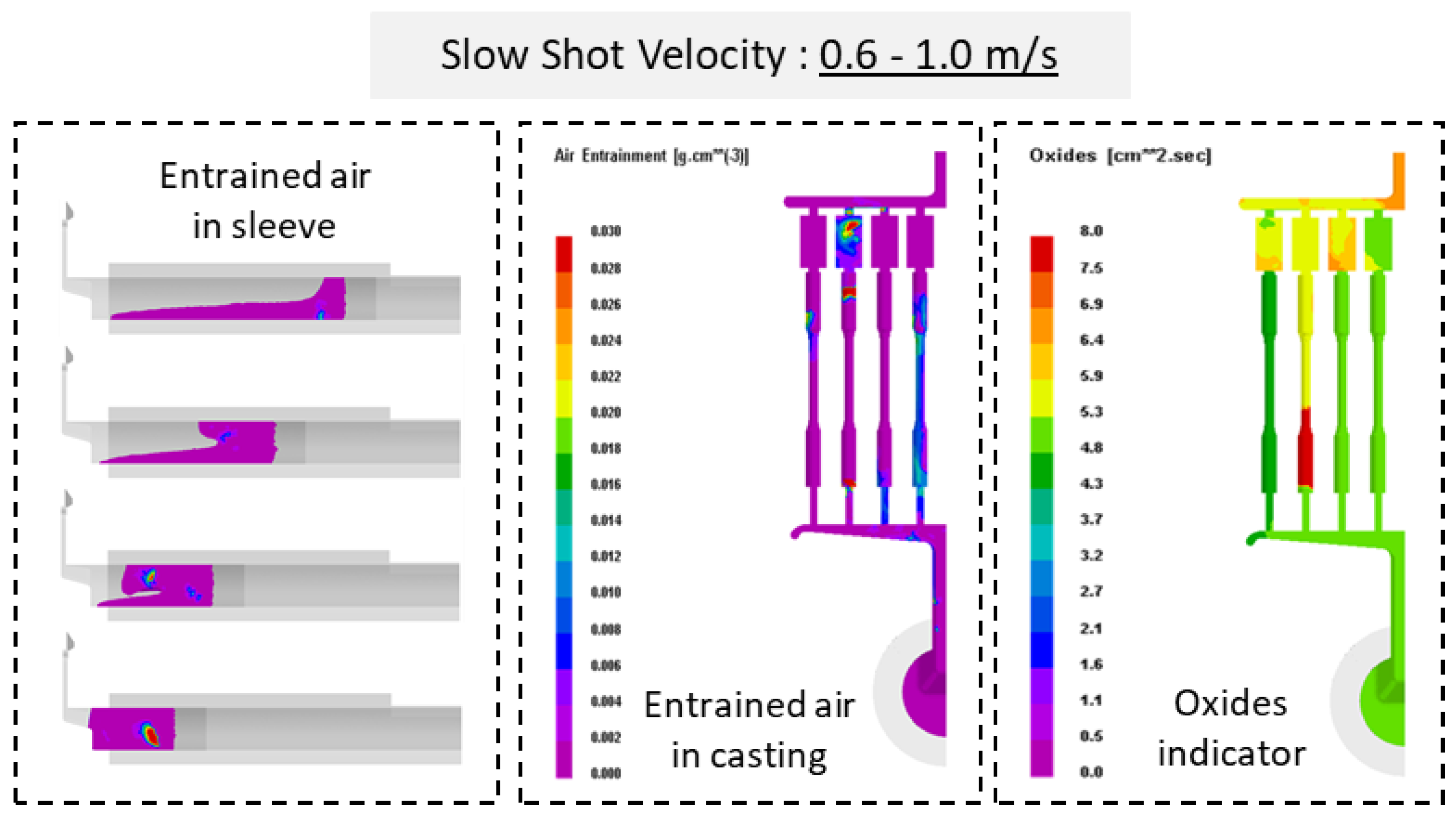
Figure 10.
The motion trajectory of particles of different sizes in the mold.
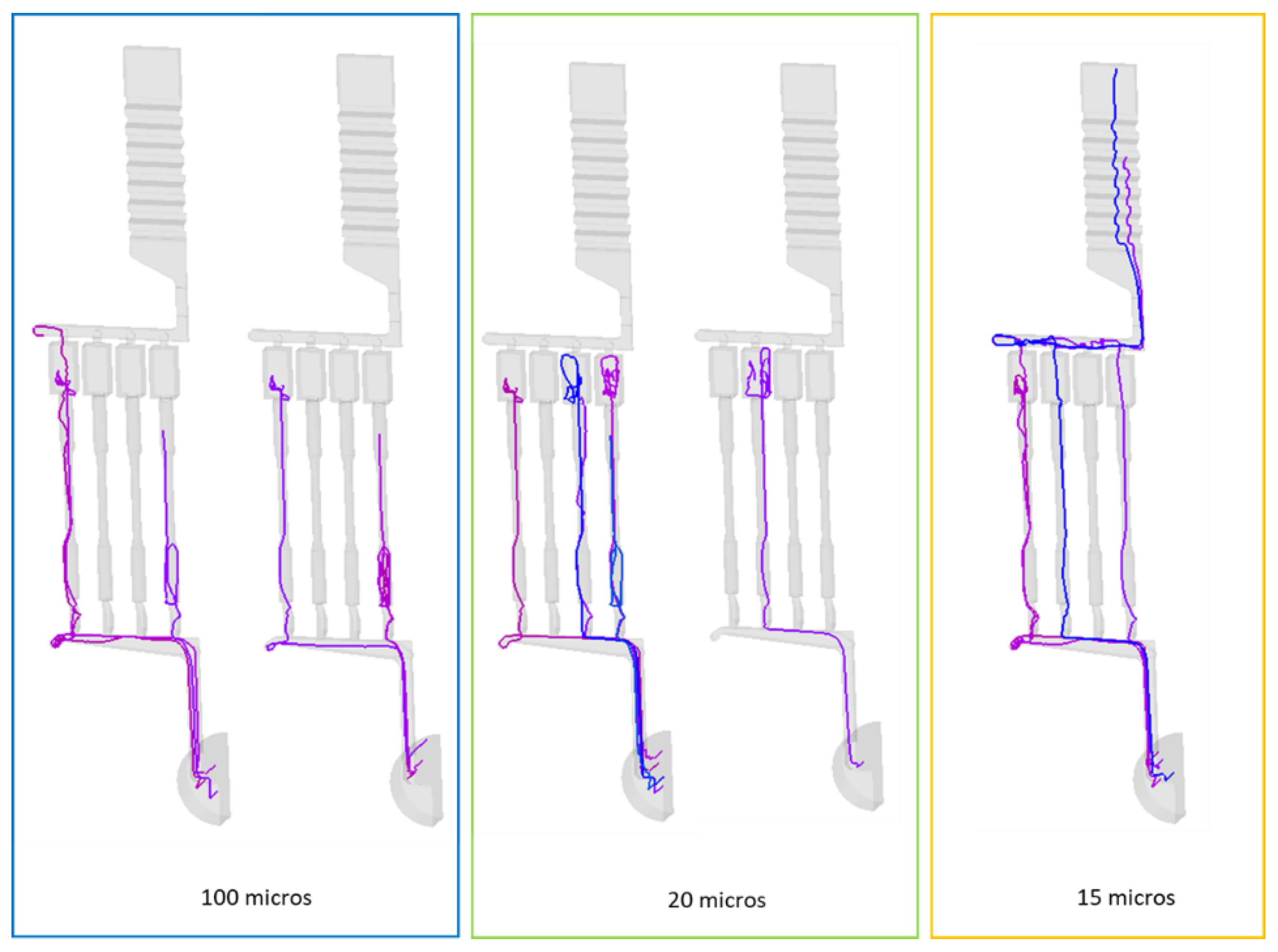
Figure 11.
6 piston slow shot acceleration modes.
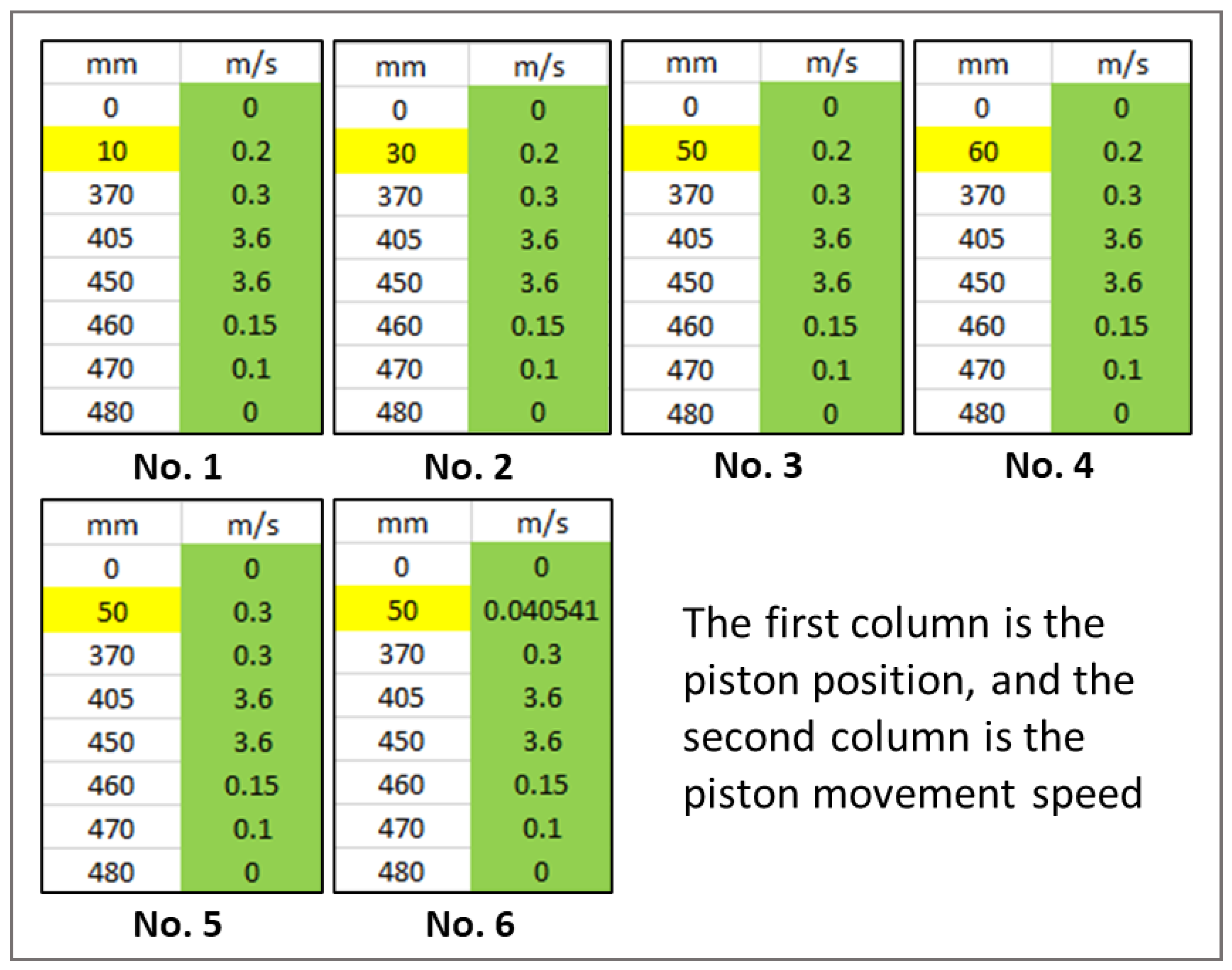
Figure 12.
The relationship between displacement and velocity under 6 piston slow shot acceleration modes.
Figure 12.
The relationship between displacement and velocity under 6 piston slow shot acceleration modes.
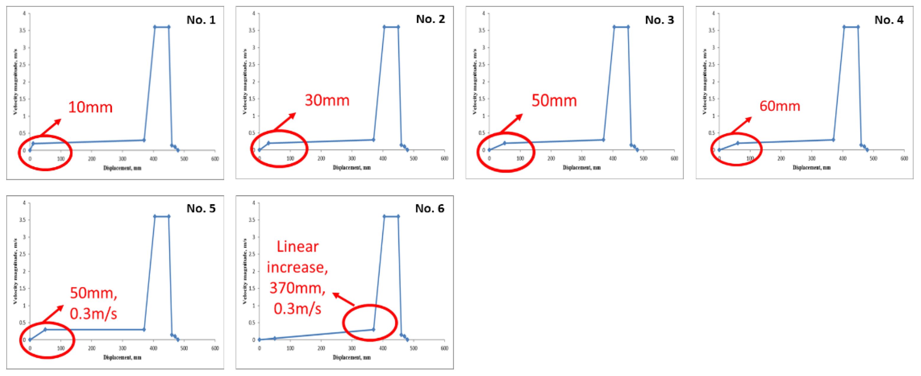
Figure 13.
Air entrapment at the casting mold under 6 piston slow shot acceleration modes.
Disclaimer/Publisher’s Note: The statements, opinions and data contained in all publications are solely those of the individual author(s) and contributor(s) and not of MDPI and/or the editor(s). MDPI and/or the editor(s) disclaim responsibility for any injury to people or property resulting from any ideas, methods, instructions or products referred to in the content. |
© 2024 by the authors. Licensee MDPI, Basel, Switzerland. This article is an open access article distributed under the terms and conditions of the Creative Commons Attribution (CC BY) license (http://creativecommons.org/licenses/by/4.0/).
Copyright: This open access article is published under a Creative Commons CC BY 4.0 license, which permit the free download, distribution, and reuse, provided that the author and preprint are cited in any reuse.


