
Submitted:
02 December 2024
Posted:
04 December 2024
You are already at the latest version
Abstract
In response to increasing challenges with respect to the reliability and durability of pipeline infrastructure, understanding the mechanisms that lead to the degradation and failure of steel pipelines is essential. This paper focuses on the analysis of selective corrosion and erosion as primary degradation mechanisms, employing advanced research methodologies, including macroscopic analysis, corrosion testing, microscopic examination, and mechanical strength testing. Selective corrosion, particularly in the heat-affected zones (HAZ) of the welds, and erosion were identified as critical damage mechanisms that often exacerbate each other. Detailed analysis of damaged pipeline segments was performed, evaluating the extent of weld degradation, and investigating the characteristics and morphology of corrosion pits. The study found that selective corrosion in longitudinal welds significantly undermines the integrity of the pipeline, with erosion further accelerating the degradation process. These findings are reinforced by strength analyzes and finite element modeling (FEM), demonstrating the critical impact of these degradation mechanisms on the structural integrity and load-bearing capacity of pipelines. The research underscores the importance of an integrated approach to monitoring and maintaining steel pipelines, highlighting the need for continued research to optimize material composition and welding techniques to mitigate susceptibility to selective corrosion and erosion. These insights are crucial in developing more robust preventive strategies to improve the service life of pipeline infrastructure.
Keywords:
selective corrosion
; erosion
; steel pipeline degradation
; welds
; strength analysis
; finite element method (FEM)
; preventive strategies
1. Introduction
In the face of growing expectations regarding the reliability and durability of industrial infrastructure, steel pipelines play an irreplaceable role in transportation systems, serving as a critical component in the distribution of resources such as crude oil, natural gas, potable water and a wide range of chemicals. As a foundation of the modern economy, they enable access to essential services and resources. Despite their significant importance, these pipelines are exposed to numerous threats that can lead to degradation and, potentially, failure. Among the primary threats is steel corrosion, which is recognized as a chemical and electrochemical process that gradually deteriorates the material when in contact with an aggressive environment. In the context of corrosion, particular attention should be given to the process of selective corrosion, due to its nearly undetectable nature, which often results in unexpected failures. This process can progress unevenly and is often invisible from the exterior. It may develop internally within the material or in areas of difficult access, complicating early detection and evaluation of the severity of the corrosion. Diagnostic methods, such as visual inspections, are often insufficient; thus, more advanced techniques, such as ultrasound, radiography, or thermography, are required. Selective corrosion can be driven by highly specific environmental factors, such as the presence of certain ions in the corrosive environment, meaning that while controlling the working environment may mitigate the risk, it does not eliminate it entirely. This process can have serious economic, environmental, and social consequences. However, it is crucial to emphasize that corrosion is not the only threat to pipeline infrastructure. Erosion, caused by the flow of media, especially those containing solid particles that can abrade the internal surface of the pipeline, poses a significant problem, leading to gradual degradation of the pipeline structure and, ultimately, to failure. The impact of both corrosion and erosion is substantial, but the influence of other threats cannot be ignored, such as hydraulic shocks, mechanical damage resulting from human activities (eg, mining-induced ground subsidence), atmospheric phenomena, or environmental interactions. Therefore, the degradation factors of steel pipelines are numerous, and managing the risks associated with their degradation requires systematic inspections, maintenance, and system upgrades to prevent failures and minimize their negative impacts.
Since corrosion is one of the main threats to steel pipeline structure, the issue of failures caused by corrosion and material degradation has been the subject of extensive scientific research. It has been found, among other things, that internal corrosion, often triggered by the interaction of pipeline material with internal media such as CO2, H2S or water, can lead to general or localized structural loss and environmentally assisted cracking, which are the main causes of pipeline failures [1,2,3]. Key factors contributing to aggressive internal corrosion, particularly in water injection pipelines, include microbial influences and the formation of deposits [4,5]. In the case of external corrosion, research indicates that environmental exposure, coating integrity, and microbiological activity play a significant role [6,7]. For both internal and external corrosion mechanisms, localized corrosion is critical, with complexity determined by various factors, including defect geometry, environmental conditions, and the presence of protective deposits [8]. Corrosion defects can significantly reduce the pressure resistance of pipelines, and localized corrosion is intensified by galvanic effects and specific environmental conditions, such as the presence of CO2 and H2S [9]. The complexity of localized corrosion mechanisms has led to the development of mechanistic models for its prediction, and the role of microbiological factors has been emphasized, especially for pipelines difficult to assess due to their working environments, such as those buried deep underground [10]. Analysis of the impact of corrosion on steel pipeline degradation also considers selective corrosion, whose intensity depends on material composition, environmental factors, and electrochemical interactions, with welds being particularly vulnerable due to galvanic coupling [11]. Environmental conditions, such as the presence of hydrocarbons and carbonates, can affect the formation and stability of passive films on pipeline steels, influencing the rate of selective corrosion [12], which presents a significant risk of sudden failure. The economic implications of corrosion highlight the importance of material selection and corrosion protection strategies for pipeline design [13]. Advances in steel composition offer promising pathways to increase corrosion resistance and ensure the safety and durability of pipeline infrastructure [14]. It is not only the base material, but also the welded joints of the pipeline, which are an integral part of the entire system, that are susceptible to corrosion and must not be overlooked. Corrosion of welded joints in steel pipelines is a multifaceted issue influenced by factors such as microstructural differences, mechanical stresses, and environmental conditions. The heat-affected zone (HAZ) is often the most vulnerable due to its altered microstructure and mechanical properties [15,16,17]. Irregularities in welded connections, such as variations in wall thickness and geometric discontinuities, can further accelerate corrosion by disrupting fluid flow and causing stress concentration [18,19,20]. Long-term exposure and specific corrosive environments, such as chloride ions, also increase the risk of corrosion and stress corrosion cracking (SCC) [21,22]. The cracking of stress corrosion is a critical issue in the analysis of steel pipeline degradation, influenced by environmental conditions, material properties, and electrochemical protection strategies [23,24]. The interaction between anodic dissolution mechanisms and hydrogen embrittlement is crucial, and the effectiveness of cathodic protection can vary depending on the applied potential [25]. In addition, soil conditions can significantly affect the susceptibility of pipelines to SCC [26,27]. Given the diversity of factors and corrosion mechanisms, it is essential to analyze the causes of steel pipeline degradation and failure, emphasizing the importance of understanding these processes, especially in the context of studying specific failure cases.
Erosion is another significant factor contributing to the degradation and failure of steel pipelines. It is a complex phenomenon that results from the interaction between material properties, environmental factors, and operational conditions. The primary focus of research is on identifying the erosion mechanisms that can lead to potential failures, highlighting the strong correlation between erosion and corrosion. The synergistic effect of solid particles in a corrosive environment with high flow dynamics poses a substantial threat to the pipeline infrastructure [28,29,30,31,32,33].
Corrosion and erosion, or their combination, are the main causes of accelerated degradation that leads to premature uncontrolled failures of steel pipelines. However, in assessing the causes of failure, other aspects that contribute to increased degradation or failure should not be overlooked. The dependence on the initial choice of steel grade and the operating conditions of the pipeline throughout its entire service life is significant. Carbon steel is the material most used because of its favorable mechanical properties and relatively low cost, but it may be inadequate when transporting media that promote corrosion or erosion. In such cases, low-alloy or stainless steels are often used, where a high chromium content ensures the formation of a protective passive layer. In some specific cases, high-strength Duplex steels are used, offering a combination of ferritic and austenitic properties that provides good strength and corrosion resistance. The use of Corten steel, which is characterized by increased corrosion resistance due to the presence of copper, chromium, or nickel, allows the formation of a protective oxide layer that acts as a barrier against further material degradation. Despite the potential advantages, the use of Corten steel requires a thorough analysis in the context of its impact on corrosion wear and pipeline degradation [34,35,36]. Hydraulic impacts, generating radial pressure waves in pipelines [37] and causing significant stress fluctuations, pose an additional challenge, as does material fatigue resulting from high cyclic pressure in a corrosive environment. In this context, the quality of welds is critical, as defects can initiate failure due to fatigue. Prolonged operation can lead to material degradation, especially on the internal surface, significantly reducing fatigue strength and the reliability of the pipeline system [38,39,40,41]. The operating environment of the pipeline presents challenges in assessing the extent of degradation and potential causes of failure. Evaluating the degree of degradation of underground pipelines is difficult, but environmental influence is crucial. These pipelines are exposed to factors such as seismic activity, ground structure disturbances from installation processes, rock mass movements in mining environments, or explosions. The literature addresses attempts to resolve issues related to these factors, but detailed descriptions of their impact on potential pipeline failures and guidelines for monitoring pipeline conditions, which would enable earlier intervention, such as replacing potentially faulty sections, have not been emphasized [42,43,44].
In the context of the critical role emphasized of steel pipelines and the challenges associated with their degradation, it can be concluded from the cited literature that particular attention should be paid to advanced research and innovations in monitoring, maintenance, and protection against corrosion and erosion to prevent uncontrolled failures. The authors of this study demonstrate that a deeper understanding of the mechanisms of pipeline damage is the key to developing more effective methods for preventing pipeline failures.
2. Methodology and Objects of Study
Research on steel pipeline failures constitutes a significant area of scientific investigation, focusing on identifying the causes and mechanisms that contribute to the degradation and failure of these structures. As part of this research process, a wide range of testing methods and analytical models are used to understand the fundamental issues underlying the structural compromise of pipelines.
Due to the necessity of accurately understanding the causes of failures and damage to steel pipelines, as well as gaining a deeper insight into the damage mechanisms themselves—essential for developing more effective failure prevention methods—it is crucial to conduct detailed research and analysis in this field. This article presents an original analysis of the causes of steel pipeline failures and degradation from the perspective of damage mechanisms, aimed at developing effective preventive strategies.
As research objects, due to the occurrence of failures, steel pipeline segments were selected, forming a surface network for the transportation of mine water, process water, and flotation waste. These pipelines are primarily made of pipes with diameters of 800 and 1000 mm, with a longitudinal SAWL seam, formed from L235 grade plates, which are joined by single-sided butt welds. The analysis focused on pipelines transporting water and flotation waste because their failures are considered among the most significant environmental threats. During an in-depth analysis of the pipes, it was found that the failure cases varied, which led to the decision to present examples of the effects of their damage. A general view of the pipe sections described is shown in Figure 1.
Figure 2 shows an example of a damaged pipeline segment resulting from the longitudinal rupture of the seam.
Visible defects in the weld caused by selective corrosion are characterized and shown in Figure 3.
It is important to note, especially in the case of the unruptured internal section, that the nature of the acting selective corrosion is evident (Figure 3c). Along the weld face, localized pits in the structure are visible, with significant longitudinal pits forming near the heat-affected zone (HAZ), which considerably reduce the cross-sectional area of the weld. At the failure site, where the longitudinal seam rupture occurred, a similar pattern of selective corrosion can also be observed (Figure 3b).
A case is also characterized in which a segment of the pipeline failed due to local buckling, caused by excessive thinning of the pipe wall, under constant pressure of the network. This case is illustrated in Figure 4.
Due to availability, for comparison with failed pipes, an analysis was also conducted on pipes that, due to their level of degradation, were replaced before failure. A characteristic feature of these pipes is the presence of hard and absorbent corrosion product coatings. This issue is illustrated in Figure 5.
After the removal of the corrosion products, this pipe also exhibits, in this case due to its earlier replacement, the initiation of degradation through the mechanism of selective corrosion. Longitudinal pits are visible near the HAZ, causing significant weakening of the weld cross-sectional area, as shown in Figure 6.
Within the group of pipes that did not fail, one was identified as atypical for the entire system, as it features a spiral SAWH seam, unlike the others. Despite the absence of cracking, selective corrosion was found along the weld face on the interior side, after cleaning it of corrosion products, as well as pits along the entire length near the HAZ of the weld, as shown in Figure 7.
Based on the presented examples from the analyzed pipelines, two groups of pipelines differing in purpose were distinguished due to the wear mechanism.
- A.
- for water transportation,
- B.
- for the transportation of flotation waste.
The distinguished types of pipeline exhibit different properties despite using the same materials. Water transport pipelines are not subject to intense abrasive wear. The most significant cause of failure is corrosion, particularly selective corrosion, which mainly affects longitudinal seams. These pipelines develop a compact, absorbent, and yet permeable layer of corrosion products on the interior. They are extremely difficult to diagnose due to internal encrustation, the nature of degradation, and the lack of easy access to the elements exposed to them. The schematic of this type of corrosion formation in the analyzed case is shown in Figure 8. This phenomenon is initiated by the retention of water (2) between the pipe material (1) and the compact, semipermeable layer of corrosion products and contaminants (3), where a saturation zone of corrosion products forms. The concentration of corrosion ions in this zone exceeds the saturation point, leading to localized precipitation of corrosion products and the formation of a water-metal interface. On the external side of the pipe, there is a protective layer (4) designed to protect the material from external factors. When this layer is present, the selective corrosion mechanisms are limited to the internal surface of the pipe, where the absence of a protective coating allows direct contact between the corrosive medium and the metal. In the pipe structure, which is not coated on the internal side, circumferential stresses (σr) occur. These stresses result from differences in the stress distribution between the inner and outer sides of the pipe, amplified by the pressure of the water network (p) acting from within the pipe. These stresses contribute to variations in the corrosion reaction rate on the internal surface of the pipe. The development of selective corrosion along the HAZ (5) is particularly intense in areas with the highest stress gradient combined with high network pressure. Here, pits (6) preferentially form: deep material damage resulting from locally intensified corrosion processes.
To properly diagnose operational problems and develop effective failure prevention strategies for steel pipelines, it is essential to understand the working conditions of such a system. It has been identified that, under standard operating conditions, the pressure in the pipes does not exceed 16 bar and observed pressure fluctuations do not exceed 50% of the baseline value. During testing, newly constructed pipelines are subjected to pressure tests at 25 bar, while new manufacturers' pipes are tested at even higher pressures, such as 55 bar. Surface pipeline installations use compensators, which allow for the accommodation of length variations in the structure due to various factors, including temperature changes, which can reach several hundred millimeters. In cases where the pipe is near a compensator, a special support is used that not only accommodates axial displacements of the pipe, but also allows the pipe to rotate relative to the support. At the support point, friction forces and loads resulting from misaligned support occur. For pipeline sections located underground, no additional supports are used, which is a standard industry practice. Exceptions are made in emergency situations where supports are used as a remedial measure to ensure the continued safe operation of the system.
From these observations, it follows that accurately characterizing the mechanisms causing pipeline failures, as well as properly understanding their operational characteristics, can lead to the development of original methods to determine the causes of failures and create effective preventive strategies.
The authors, addressing this issue, conducted studies on steel pipe fragments to identify potential causes of degradation and failure in steel pipelines and to evaluate the possibilities for preventing these phenomena. The basis for analyzing the complex problem of selective corrosion was the assessment of the level of degradation of the welded joints. To achieve this goal, metallographic sections were prepared in cross sections of the longitudinal welds, enabling a detailed analysis of the material structure. Additionally, to identify the causes of failure, studies were carried out on damaged pipeline sections, focusing on the quality of the joints. Corrosion analysis included corrosion testing in a ferroxyl reagent, which allowed for determining the material's susceptibility to corrosion in this specific environment. Complementary potentiometric measurements were performed on the areas of the welded joints to assess the electronic properties of the welds and the electrochemical potentials affecting the corrosion processes. Selected pipeline sections were also subjected to microscopic examinations, allowing for a precise investigation of the nature and morphology of the pits formed in the heat-affected zones (HAZ) of the longitudinal welds. Subsequently, tensile tests were conducted on selected pipeline segments. The purpose of these tests was to determine the actual strength parameters of the materials used, quantifying the impact of degradation on the mechanical properties of the pipes. The final stage of the research involved non-linear strength analyzes using the finite element method (FEM) for the welded joints of the pipelines, considering different levels of degradation. These analyses enabled computer modelling of the stress state in welded joints and prediction of their response to operational loads in the context of advanced corrosion processes.
3. Research Conducted on the Objective of the Study
As a result of analyzing the degraded pipeline fragments, an attempt was made to investigate the causes of their degradation and the failure to develop effective preventive strategies. A series of studies were conducted on the degraded pipe fragments, as described in the following subsections.
3.1. Evaluation of the Degradation Level of Welded Joints
The level of degradation of the welded joints was assessed on the basis of visual inspections and macroscopic examinations. Figure 9 shows a segment of the pipe after failure with a ruptured longitudinal weld, where the arrows indicate the locations with material loss in the weld.
The segment of the pipe shown in Figure 10 reveals varying degrees of corrosion loss along the weld on the internal side of the pipe. To evaluate and determine the extent of weld degradation, a segment of the same pipe that had not yet fractured was selected, as shown in Figure 10.
The selected segment (Figure 10) was divided to perform a macroscopic analysis of the welded joint. The selected fragments are shown in Figure 11.
The degree of weld degradation in the selected samples is shown in the macrographs (Figure 12) of the metallographic sections for the example segments.
3.2. Assessment of Weld Quality in Damaged Pipeline Segments
To confirm the location of anodic areas in the welded joints of the pipes, corrosion tests were conducted on the joints described previously. The corrosion test aimed to identify areas where oxidation (anode) and reduction (cathode) reactions occur. The test was performed using a ferroxyl reagent. The results of the tests, for example, welds with the highest degree of degradation are shown in Figure 13.
These tests were qualitative in nature and provided only an approximate visualization of the areas where corrosion cells form. The results obtained confirmed the assumptions about the location, specifically the weld and its heat-affected zone (HAZ).
Quantitative studies of the corrosivity of welded pipe joints were also conducted to determine potential differences between weld areas, HAZ, and pipe material. Based on the results of the potentiometric test, the susceptibility to galvanic corrosion can be assessed in or near the weld area.
The designations of the joint samples subjected to potentiometric measurements are summarized in Table 1. In addition to joint samples cut directly from the pipe, comparative test joints were made using the steel from the examined pipe, welded with an acidic electrode (with a chemical composition like the pipeline steel) and an electrode with COR-TEN steel filler metal. The chemical compositions of the electrodes used are provided in Table 2.
Electrochemical studies were conducted in a three-electrode system: the working electrode – sample, the reference electrode – saturated calomel electrode and the counter electrode – platinum wire. The studies were performed in three areas of the sample: the weld area, the heat affected zone (HAZ), and the base material. Potential changes were recorded over a period of 1000 seconds.
Figure 14, Figure 15 and Figure 16 present the results of potential recording studies over time. Each figure shows the potential curves for four different types of samples.
Table 3 presents the results of the electrochemical study, showing the potential values of the tested samples in three areas at 1000 seconds.
3.3. Microscopic Examination of Pitting in the Heat Affected Zone of the Welded Joints
Microscopic examinations were conducted on specimens in the nital-etched state, observing cross sections of previously selected samples. A Leica M205 stereomicroscope was used for the study. The results of microscopic observations of pitting in the heat-affected zone (HAZ) based on examples of sections (Figure 12) are presented in Figure 17.
3.4. Strength Testing of Pipelines and Welded Joints
A static tensile test at room temperature was performed according to the PN-EN ISO 6892-1:2016-09 standard, method B30. The test was carried out using a Zwick/Roell Z100 THW universal testing machine equipped with an automatic macroXtens II extensometer.
Several types of samples were selected for the tests. Material was taken from the base structure of the pipe (Figure 18) transversely to the axis of the welded joint that shows the presence of corrosion pits (SP). Figure 19 shows representative SP test specimens. The summary results of the mechanical properties for each test are presented in Table 4.
Figure 20 presents examples of tensile curves obtained during tests for SP samples, which, due to the nature of the existing pits, play a crucial role in the assessment method for determining the causes of pipeline failures.
3.5. Finite Element Method (FEM) Strength Analysis of Degraded Welded Joints
One of the research topics was to determine the levels of stress and plastic strain in areas of selective corrosion in longitudinal welds. To assess the impact of weld degradation on the strength of the welded joint in the pipeline, preliminary numerical calculations were conducted using the finite element method. The first stage involved the construction of a geometric model based on the data provided by the client. Due to the use of non-linear calculations, a symmetrical model was adopted for a 60 ° section of the pipe. Figure 21 shows the schematic used to model the pipe section and the example dimensions of the model.
In the non-linear numerical calculations, the maximum operating pressure in the pipeline was set at 16 bar. The numerical simulations were conducted in multiple stages, gradually reducing the weld thickness by increments of 1 mm from the initial thickness, ending in the removal of half of the weld. The results, presented as contour graphs of circumferential normal stresses and equivalent plastic strains, are consistently shown for various representative levels of weld degradation in Figure 22 and Figure 23.
Subsequently, models were developed to more accurately represent the shape of the pit formed along the weld due to corrosion (Figure 24), and a new series of non-linear calculations was performed, achieving a higher level of maximum pressure. The objective of these calculations was to determine the allowable degradation of the pipe due to selective corrosion, assuming that it affects the longitudinal weld.
The results of the numerical analyzes, presented as contour plots of circumferential normal stresses and equivalent plastic strains at a pressure of 30 bar and a pit depth of 6 mm, are shown in Figure 25.
Figure 26 illustrates the impact of pressure and the degree of joint degradation on the plastic strain at the bottom of the notch in the hole caused by selective corrosion.
4. Summary and Discussion
The authors present a comprehensive analysis of the causes of industrial steel pipeline degradation and failure, focusing on damage mechanisms and methods for their prevention.
Various research methods were applied in the study; however, the initial step was to determine the degree of degradation of the welded joints in selected areas of the steel pipeline. From the macrostructures shown in Figure 13, it is evident that corrosion in the case of welded joints is initiated primarily in the heat-affected zone (HAZ) near the internal weld of the pipe, first along the fusion boundary (c and d), and over time also within the internal weld itself (a and b). This is caused by the action of selective corrosion of the HAZ and selective corrosion of the weld metal. Additionally, localized pitting corrosion occurs in the weld, penetrating the weld metal (e and f). As a result of deep pit penetration, selective corrosion extends into the HAZ from the external weld of the pipe (e, f, g, h). In some cases, the weld penetrates the entire thickness of the joint (f). It was observed that selective corrosion of the HAZ from the internal weld significantly weakened the load-bearing cross section of the joint, leading to pipe failure under external loads. Analysis of the degree of degradation of the welded joint in pipes transporting water indicated the importance of selecting an appropriate filler metal for welding transmission pipelines, one that would change the potential distribution in the weld joint areas so that the weld metal does not become the anode. Consequently, potentiometric measurements were performed on selected welded joints from pipes and joints made with specific filler metals to investigate the potential distribution of the weld metal, the HAZ, and the base material. For these types of measurements, in most cases, the characteristic shape of the curves for the three types of area relative to a particular sample was similar. However, differences were observed between the various types of samples. In some cases, a small initial increase in the potential difference was observed at the beginning of the measurement, followed by a slow decline. No significant differences were recorded in the final potential values. In extreme cases, the potential difference, depending on the type of area, ranged from 20 to 40 mV. Potentiometric studies suggest that the weld metal is the anodic area most often, but in some instances, the base material can become the anodic area, which would be a more favorable configuration due to the surface area differences between the two regions of the welded joint. The results presented refer to a stationary state in still water, where a certain electrochemical equilibrium is established over time. This can be observed in the graphs, which show that the initial potentials for the weld, the HAZ, and the base material change in value. In an actual pipeline, however, the water is in constant motion, and such an equilibrium state is not reached. Therefore, the results obtained are approximate values that are useful for the preliminary selection of material pairs for steel and filler metal. Potential measurement results alone are not sufficient to evaluate the suitability of material selection for the welded joint. Extended laboratory corrosion tests, followed by validation in practical corrosion tests, are required to comprehensively assess material compatibility.
Microscopic analysis of pits in the heat-affected zone (HAZ) revealed that a common feature for many observed cross sections of both longitudinal and circumferential welds is the presence of selective corrosion in the HAZ. As a result, the resulting corrosion pits are symmetrically distributed around the weld, forming pairs of longitudinal grooves along the welded joint, a typical characteristic of corrosion known as tramline corrosion. The appearance and depth of the pits vary between different pipelines. In some cases, even along the length of a single welded joint, the morphology and depth of the pits change. The pits visible on the cross sections, penetrating the material along the fusion line and reflecting the shape of the weld, best illustrate the selective nature of the corrosion. Thus, these areas must exhibit lower nobility than the base material of the pipe and even the weld metal itself. The anodic character of the heat-affected zones is influenced not only by the chemical composition of the weld metal and the base material but also by the presence of nonmetallic inclusions, welding imperfections, residual stresses, or the microstructural morphology resulting from the applied welding parameters. For these reasons, the starting and end points of the longitudinal weld in a pipe do not corrode in the same manner as the middle section, despite the identical chemical composition of the filler metal. Furthermore, heat generated during subsequent circumferential weld passes may have caused stress relief in these areas of the longitudinal welds, thereby affecting their susceptibility to corrosion.
A crucial aspect of the study was the strength testing, which was performed using tensile testing. Based on the tensile tests performed, it was determined that the strength parameters obtained, along with the expanded measurement uncertainty, correspond to the structural steel grade S235 (JR, J0, J2) according to the PN-EN 10025-2:2004 standard. The welds (SSH samples) exhibited a higher yield strength and tensile strength than the corresponding base materials of the pipelines. In one case, an SP sample fractured outside the welded joint. The remaining samples failed within the weld due to internal defects in the joint. All SP samples taken from corroded areas of the pipe fractured at the welded joints, predominantly along the fusion line. The pits formed due to corrosion processes acted as stress concentrators and served as initiation points for cracks that propagated along the boundary between the weld beads and the HAZ.
Knowing the nature of joint degradation, the exact appearance of the resulting pits, and the material data collected from the analyzed pipe samples, Finite Element Method (FEM) strength calculations were also performed. The strength properties of the material indicate a strain level of approximately 15% at which material rupture can occur. However, in many cases, the material tests showed higher strain levels that exceeded 30%. A strain level of 15% is almost guaranteed if there are no hidden welding defects, such as slag inclusions or lack of fusion, near the pit within the joint. The observed degradation patterns generally feature smaller differences in thickness and fewer abrupt contour changes, except in cases of extreme degradation levels that occurred in the pipe. The plastic deformation at the bottom of the notch (pit) as a function of material loss depth (Figure 28) was determined under the assumption of an operating pressure of 16 bar. For a pipeline with a diameter of 1000 mm, the loss of thickness permitted is 8 mm, assuming a 10% plastic strain level (with a safety factor of 1.5 for strain and 1.3 for pressure - non-online relationship). When assessing the allowable degree of wear, the level of cross-sectional stress in the transverse direction to the weld is crucial. The remaining active cross section, degraded by corrosion, exhibits a uniform stress distribution, with stress levels only reaching the yield strength of the hardened material at the notches. At the bottom of the notch, the permissible plastic strain level is critical. When evaluating the acceptable degree of degradation, the thickness of the active cross-section is essential. Measuring this thickness is practically impossible due to the internal and external surface shapes, even if access to these surfaces is available, as common diagnostic methods are insufficient. Ultrasonic wall thickness measurements do not accurately reflect the true minimum thickness. The calculation results indicate that for pipes with a diameter of 1000 mm, the minimum wall thickness is 8 mm, and the pipeline should withstand a pressure of 16 bar, provided there are no extremely unfavorable linear material losses caused by selective corrosion. For pipes with larger diameters, the minimum wall thickness may be proportional, maintaining a constant ratio of minimum thickness to diameter.
A detailed discussion of pipeline corrosion studies was also presented, covering both internal corrosion caused by interactions with media such as CO₂ and H₂S and external corrosion, where environmental exposure and coating integrity play a crucial role. The general principles highlighted in the literature, as referenced in [1,2,3], were reflected in specific cases of damage investigated by the authors, demonstrating how these theories apply in practice. The research carried out allowed for a more precise understanding of how the mentioned corrosion processes affect specific degraded sections of the pipeline.
Furthermore, erosion is frequently depicted in the literature as a significant factor in degradation, often acting synergistically with corrosion. Referring to studies such as [28,29,30,31,32,33], the authors analyzed erosion mechanisms in practice, identifying typical erosion damage features in the examined pipeline segments. This comparison of observed damage with cases described in the literature provided a better understanding of the role of erosion in pipeline degradation.
Special attention was also paid to selective corrosion and its impact on welds and heat affected zones (HAZs), which can lead to corrosion-induced cracking. References [11,12] often focus on this issue, but the authors went further by conducting detailed macroscopic and microscopic investigations. This allowed them to identify and present new evidence of the impact of selective corrosion on the degradation of welded joints, expanding on general theories with specific empirical data.
The topic of stress corrosion cracking (SCC) cannot be overlooked, as its complexity and the influence of multiple factors are emphasized in the literature, particularly in references [23,24]. Using FEM and strength tests, the authors were able to investigate the effects of stress and material degradation on the susceptibility of welds to SCC. This study provides a new perspective on managing the risk of SCC-related failures, making a significant contribution to the development of prevention methods for such damage.
Thus, the authors used existing theories and research findings to gain a deeper understanding of damage mechanisms and developed new investigative and preventive methodologies.
5. Conclusions
The research carried out allowed for a comprehensive understanding of the damage mechanisms in steel pipelines, selective corrosion and erosion identified as the main contributing factors to their degradation. Physical analysis of damaged pipeline sections, corrosion tests, microscopic examinations, and strength tests allowed the precise identification of potential causes of failure and the evaluation of preventive measures.
Specifically, the studies confirmed that selective corrosion, initiated primarily in the heat-affected zone (HAZ) near the internal weld of the pipe, is a critical mechanism leading to significant degradation of the welded joints. Locally occurring pitting corrosion further accelerates this degradation process, and the deep penetration of pits results in selective corrosion extending to the external weld, weakening the load-bearing cross section of the joint.
Erosion, as the second major degradation mechanism, in combination with corrosion, creates a complex challenge to maintain the durability and reliability of steel pipelines. The analysis demonstrated a strong correlation between erosion and corrosion, emphasizing the need for a holistic approach to risk management.
Tensile tests revealed that the strength properties of the pipe material are consistent with the expectations for L235-grade steel, indicating the adequate quality of the material used in the construction of the pipeline. However, the observed damage to the welded joints, mainly along the fusion line, confirms that selective corrosion significantly reduces the strength of the welded joint.
Based on finite element method (FEM) numerical analyzes, it was determined that the degree of weld degradation significantly affects the strength of the welded joint. Modelling stresses and strains in areas affected by selective corrosion provided a better understanding of the impact of degradation on the structural integrity of pipelines.
The authors' investigations of the causes of failure and degradation of steel pipelines provide valuable insights into key damage mechanisms and offer guidance for developing more effective preventive strategies. Understanding these processes is crucial to ensuring the long-term durability and reliability of pipeline infrastructure, which is fundamental to environmental and economic safety.
This work represents a significant contribution to the field of research on steel pipeline degradation, highlighting a comprehensive approach to addressing corrosion and erosion issues. Analysis is an important step toward improving the safety and longevity of pipeline infrastructure, offering practical recommendations for preventing failures and mitigating their adverse effects. The authors emphasize the importance of continuing research in this area, which could further advance the development of effective diagnostic and protective methods for industrial pipelines.
Funding
This research received no external funding.
Conflicts of Interest
The authors declare no conflicts of interest.
References
- Hagarová, M.; Cervová, J.; Jaš, F. Selected types of corrosion degradation of pipelines. Koroze a ochrana materiálu 2015, 59, 30–36. [Google Scholar] [CrossRef]
- Ossai, C.I.; Boswell, B.; Davies, I.J. Predictive Modelling of Internal Pitting Corrosion of Aged Non-Piggable Pipelines. J Electrochem Soc 2015, 162, C251–C259. [Google Scholar] [CrossRef]
- Askari, M.; Aliofkhazraei, M.; Afroukhteh, S. A comprehensive review on internal corrosion and cracking of oil and gas pipelines. J Nat Gas Sci Eng 2019, 71, 102971. [Google Scholar] [CrossRef]
- Comanescu, I.; Melchers, R.E.; Taxén, C. Corrosion and durability of offshore steel water injection pipelines. Ships and Offshore Structures 2016, 11, 424–437. [Google Scholar] [CrossRef]
- Melchers, R.E. Long-Term Corrosion of Parked and Abandoned Offshore Steel Pipelines. In Volume 3: Materials Technology; Pipelines, Risers, and Subsea Systems, American Society of Mechanical Engineers, Jun. 2023. [CrossRef]
- Eslami, A.; Kania, R.; Worthingham, B.; Boven, G.V.; Eadie, R.; Chen, W. Corrosion of X-65 Pipeline Steel Under a Simulated Cathodic Protection Shielding Coating Disbondment. Corrosion 2013, 69, 1103–1110. [Google Scholar] [CrossRef]
- Hagarová, M.; Cervová, J.; Jaš, F. Selected types of corrosion degradation of pipelines. Koroze a ochrana materiálu 2015, 59, 30–36. [Google Scholar] [CrossRef]
- Alamri, A.H. Localized corrosion and mitigation approach of steel materials used in oil and gas pipelines – An overview. Eng Fail Anal 2020, 116, 104735. [Google Scholar] [CrossRef]
- Esmaeely, S.N.; Zhang, W.; Brown, B.; Singer, M.; Nešić, S. Localized Corrosion of Mild Steel in Marginally Sour Environments. CORROSION 2017, 73, 1098–1106. [Google Scholar] [CrossRef]
- Brown, B.; Li, H.; Nesic, S. Predicting Localized CO2 Corrosion In Carbon Steel Pipelines. Corrosion 2011.
- Luo, S.J.; Wang, R. Identification of the selective corrosion existing at the seam weld of electric resistance-welded pipes. Corros Sci 2014, 87, 517–520. [Google Scholar] [CrossRef]
- Eliyan, F.F.; Kish, J.R.; Alfantazi, A. Corrosion of New-Generation Steel in Outer Oil Pipeline Environments. J Mater Eng Perform 2017, 26, 214–220. [Google Scholar] [CrossRef]
- Meenakshi, S.K. A STUDY OF CORROSION CONTROL IN PIPELINES. PARIPEX INDIAN JOURNAL OF RESEARCH 2021, 48–49. [Google Scholar] [CrossRef]
- Alkhimenko, A. Corrosion testing of experimental steels for oilfield pipelines. E3S Web of Conferences 2019, 121, 01001. [Google Scholar] [CrossRef]
- Shirinzadeh-Dastgiri, M.; Mohammadi, J.; Behnamian, Y.; Eghlimi, A.; Mostafaei, A. Metallurgical investigations and corrosion behavior of failed weld joint in AISI 1518 low carbon steel pipeline. Eng Fail Anal 2015, 53, 78–96. [Google Scholar] [CrossRef]
- Cao, X.; et al. Corrosion behavior of the weld joint of X80 pipeline steel in an acidic red soil. Mater Res Express 2020, 7, 036527. [Google Scholar] [CrossRef]
- Zongxiang, Y.; Shan, J.; Gang, W.; limeng, Y.; Deping, J.; Zhongwen, Z. Study on the Corrosion Behaviours of X80 Pipeline Steel Joints Fabricated via Hot-Wire Tungsten Inert Gas Welding. Int J Electrochem Sci 2019, 14, 2672–2682. [Google Scholar] [CrossRef]
- Qiao, Q.; Cheng, G.; Wu, W.; Li, Y.; Huang, H.; Wei, Z. Failure analysis of corrosion at an inhomogeneous welded joint in a natural gas gathering pipeline considering the combined action of multiple factors. Eng Fail Anal 2016, 64, 126–143. [Google Scholar] [CrossRef]
- Hasan, F.; Iqbal, J.; Ahmed, F. Stress corrosion failure of high-pressure gas pipeline. Eng Fail Anal 2007, 14, 801–809. [Google Scholar] [CrossRef]
- Maruschak, P.; Poberezhny, L.; Pyrig, T. Fatigue and brittle fracture of carbon steel of gas and oil pipelines. Transport 2013, 28, 270–275. [Google Scholar] [CrossRef]
- Nyrkova, L.I.; Prokopchuk, S.M.; Goncharenko, L.V.; Osadchuk, S.O. Corrosion and mechanical behavior of 17G1S-U pipeline steel and its weld joint of in the terms simulating operational conditions. J Phys Conf Ser 2021, 2045, 012022. [Google Scholar] [CrossRef]
- Tsyrul’nyk, O.T.; Voloshyn, V.A.; Petryna, D.Yu.; Hredil’, M.I.; Zvirko, O.I. Degradation of properties of the metal of welded joints in operating gas mains. Materials Science 2011, 46, 628–632. [Google Scholar] [CrossRef]
- Li, G.F.; Huang, C.B.; Guo, H.; Yang, W. Stress Corrosion Cracking of Pipeline Steel in Soil Environments of Eastern China. Key Eng Mater 2007, 353–358, 223–226. [CrossRef]
- Zheng, W.; Elboujdaini, M.; Revie, R.W. Stress corrosion cracking in pipelines. In Stress Corrosion Cracking, Elsevier, 2011, 749–771. [CrossRef]
- Liu, Z.Y.; Li, X.G.; Cheng, Y.F. Mechanistic aspect of near-neutral pH stress corrosion cracking of pipelines under cathodic polarization. Corros Sci 2012, 55, 54–60. [Google Scholar] [CrossRef]
- Nasibullina, O.A.; Rizvanov, R.G. The Study of the Destruction of Pipelines, Subject to Stress Corrosion Cracking. Materials Science Forum 2020, 992, 695–699. [Google Scholar] [CrossRef]
- Velazquez, Z.; Guzman, E.; Espinosa-Medina, M.; Contreras, A. Stress Corrosion Cracking Behavior of X60 Pipe Steel in Soil Environment. MRS Proceedings 2009, 1242, S4-P131. [Google Scholar] [CrossRef]
- Islam, Md. A.; Farhat, Z.N.; Ahmed, E.M.; Alfantazi, A.M. Erosion enhanced corrosion and corrosion enhanced erosion of API X-70 pipeline steel. Wear 2013, 302, 1592–1601. [Google Scholar] [CrossRef]
- Yu, B.; Li, D.Y.; Grondin, A. Effects of the dissolved oxygen and slurry velocity on erosion–corrosion of carbon steel in aqueous slurries with carbon dioxide and silica sand. Wear 2013, 302, 1609–1614. [Google Scholar] [CrossRef]
- Islam, Md. A.; Farhat, Z. Erosion-corrosion mechanism and comparison of erosion-corrosion performance of API steels. Wear 2017, 376–377, 533–541. [CrossRef]
- Singh, J.; Singh, S.; Pal Singh, J. Investigation on wall thickness reduction of hydropower pipeline underwent to erosion-corrosion process. Eng Fail Anal 2021, 127, 105504. [Google Scholar] [CrossRef]
- POSTLETHWAITE, J.; TINKER, E.B.; HAWRYLAK, M.W. Erosion-Corrosion in Slurry Pipelines. CORROSION 1974, 30, 285–290. [Google Scholar] [CrossRef]
- Li, Q.; Liu, B. Erosion-Corrosion of Gathering Pipeline Steel in Oil-Water-Sand Multiphase Flow. Metals (Basel) 2022, 13, 80. [Google Scholar] [CrossRef]
- Kryzhanivs’kyi, E.I.; Nykyforchyn, H.M. Specific features of hydrogen-induced corrosion degradation of steels of gas and oil pipelines and oil storage reservoirs. Materials Science 2011, 47, 127–136. [Google Scholar] [CrossRef]
- Dzioba, I.; Zvirko, O.; Lipiec, S. Assessment of Operational Degradation of Pipeline Steel Based on True Stress–Strain Diagrams. 2021, 175–187. [CrossRef]
- Nykyforchyn, H.; et al. Assessment of Operational Degradation of Pipeline Steels. Materials 2021, 14, 3247. [Google Scholar] [CrossRef]
- Lopa, I.V.; Proskuriakov, N.E.; Zhukaev, A.I. Radial waves of pipeline pressure at the hydraulic shock. J Phys Conf Ser 2019, 1210, 012083. [Google Scholar] [CrossRef]
- Yu, M.; Chen, W.; Kania, R.; Boven, G.V.; Been, J. Crack propagation of pipeline steel exposed to a near-neutral pH environment under variable pressure fluctuations. Int J Fatigue 2016, 82, 658–666. [Google Scholar] [CrossRef]
- Delyová, I.; Sivák, P.; Trebuňa, F.; Hricová, B. Influence of Material Structure and its Properties on Predicting Life of Pressure Pipelines. Applied Mechanics and Materials 2014, 611, 430–435. [Google Scholar] [CrossRef]
- Kuskov, V.N.; Kovenskiy, I.M.; Kuskov, K.V. The peculiarities of fatigue failure for pipe steels of different strength classes (pipes with welds). 2014, 889–894. [CrossRef]
- Sosnovskii, L.A.; Vorob’ev, V.V. The Influence of Long Operation on Fatigue Strength of Pipe Steel. Strength of Materials 2000, 32, 523–529. [Google Scholar] [CrossRef]
- Ebrahimi, E.; Tekeste, M.Z.; Horton, R.; Hanna, H.M. Buried pipeline installation impacts on soil structure and crop root decomposition. Agricultural & Environmental Letters 2022, 7. [CrossRef]
- Jiang, N.; et al. Blasting vibration effect on the buried pipeline: A brief overview. Eng Fail Anal 2021, 129, 105709. [Google Scholar] [CrossRef]
- Psyrras, N.K.; Sextos, A.G. Safety of buried steel natural gas pipelines under earthquake-induced ground shaking: A review. Soil Dynamics and Earthquake Engineering 2018, 106, 254–277. [Google Scholar] [CrossRef]
Figure 1.
Example segments of the analyzed pipes
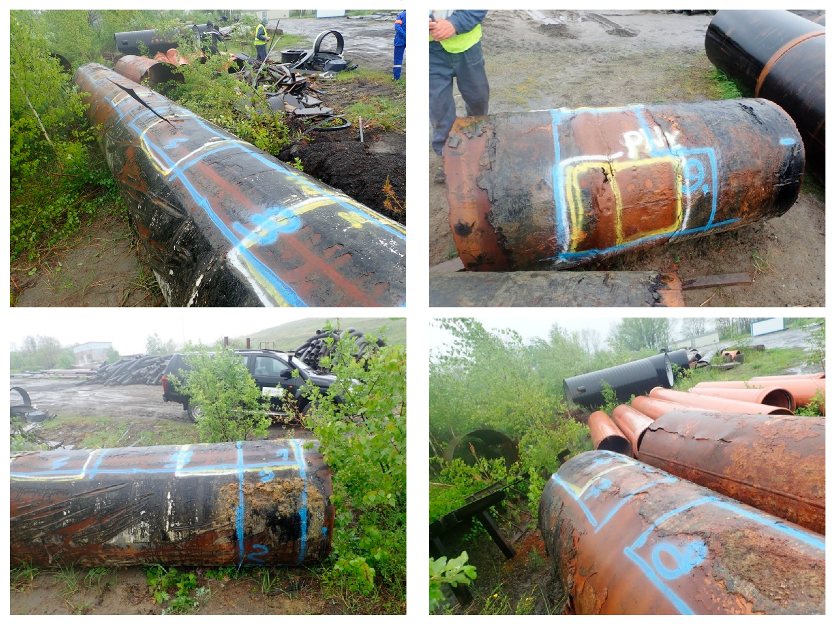
Figure 2.
Example of a damaged water pipeline segment – longitudinal seam rupture: (a) General view along the crack; (b) Close-up view of the seam rupture location.
Figure 2.
Example of a damaged water pipeline segment – longitudinal seam rupture: (a) General view along the crack; (b) Close-up view of the seam rupture location.
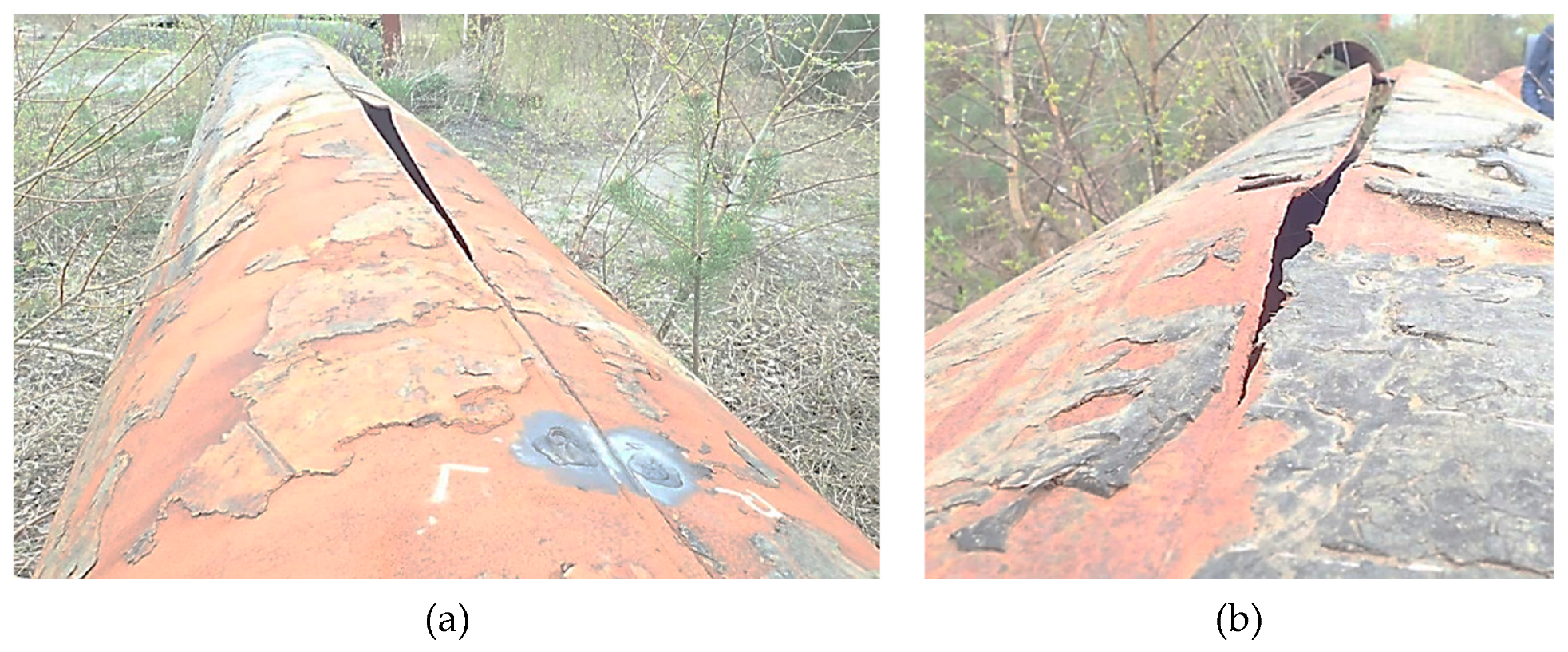
Figure 3.
Longitudinal weld rupture in pipe P1, with visible defects in the weld: (a) View from the outside of the pipe; (b) View from the inside of the pipe; (c) Weld from the inside of the pipe on the unruptured section after cleaning.
Figure 3.
Longitudinal weld rupture in pipe P1, with visible defects in the weld: (a) View from the outside of the pipe; (b) View from the inside of the pipe; (c) Weld from the inside of the pipe on the unruptured section after cleaning.
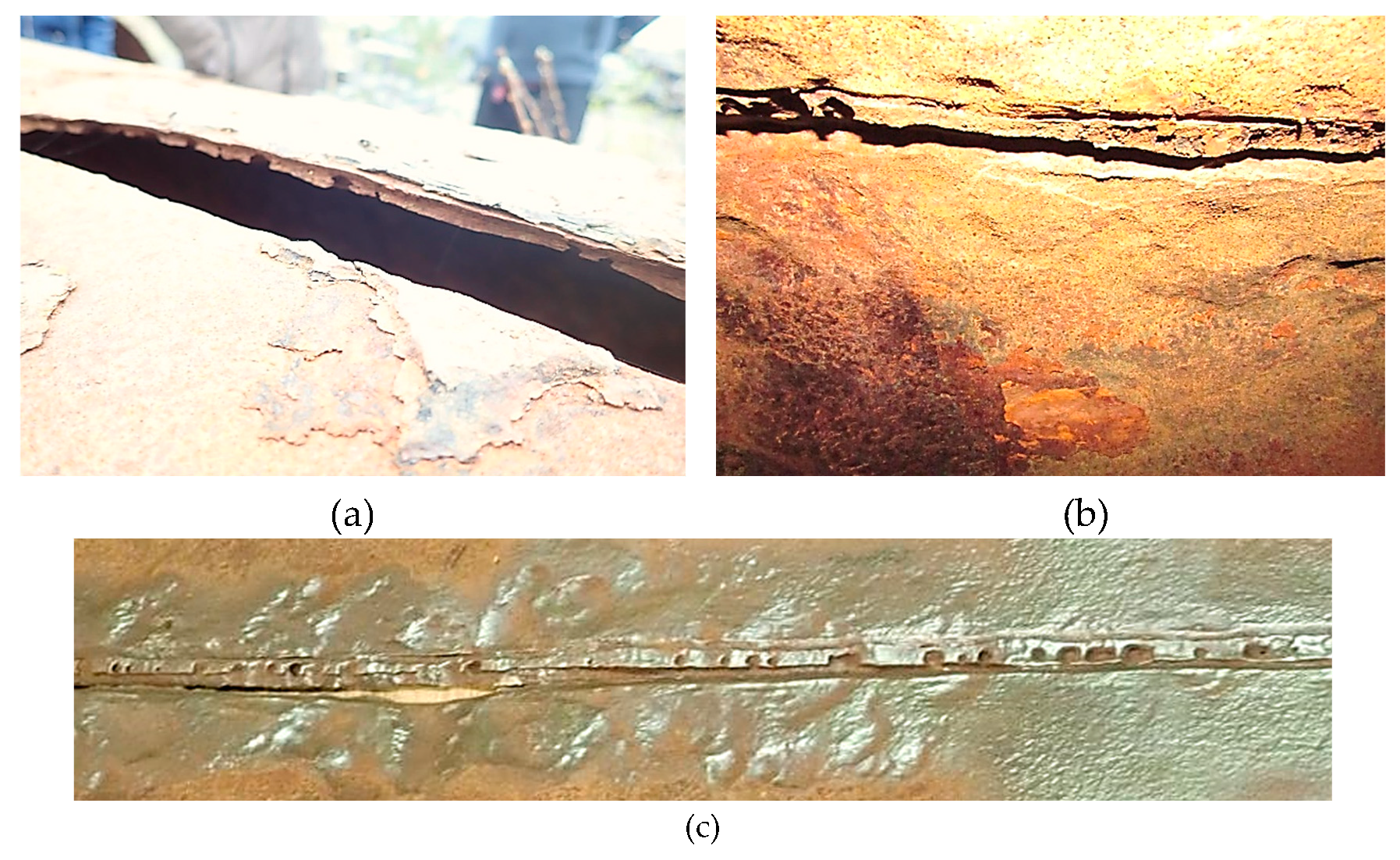
Figure 4.
Pipeline segment cut after failure caused by wall thinning
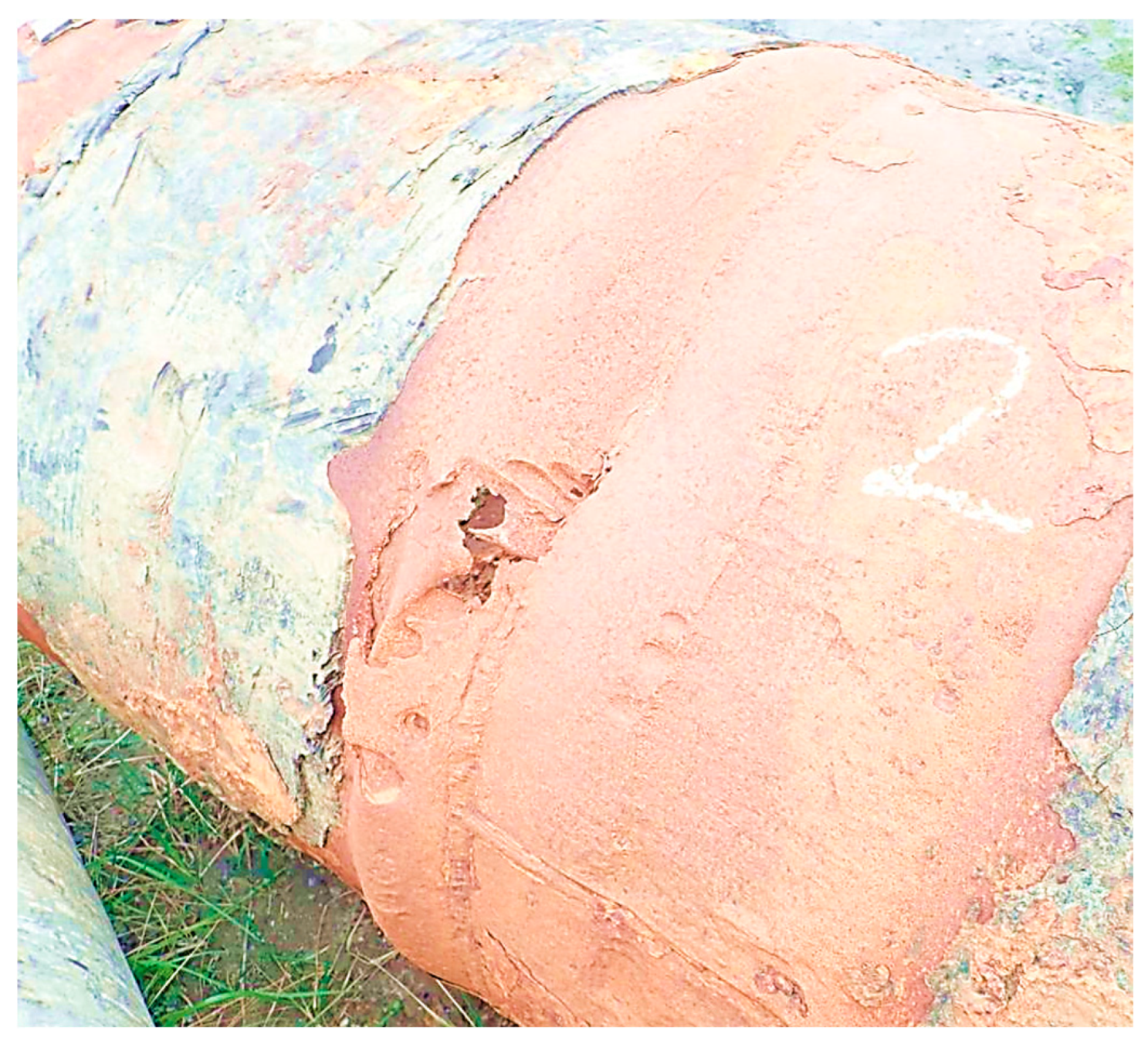
Figure 5.
Hard, compact, subsurface permeable corrosion product coatings that separate the pipe material from the water flow inside the pipe: (a) Start of the pipe seam; (b) Mechanical separation of the crust.
Figure 5.
Hard, compact, subsurface permeable corrosion product coatings that separate the pipe material from the water flow inside the pipe: (a) Start of the pipe seam; (b) Mechanical separation of the crust.
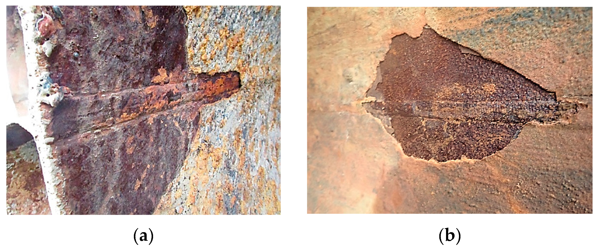
Figure 6.
Pipe after the removal of corrosion products, showing characteristic pits that degrade the longitudinal weld of the pipe.
Figure 6.
Pipe after the removal of corrosion products, showing characteristic pits that degrade the longitudinal weld of the pipe.
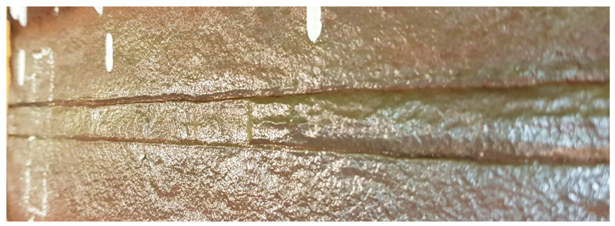
Figure 7.
Pipe with a spiral SAWH seam: Longitudinal seam rupture in pipe P1, with visible defects in the weld: (a) Seam with visible corrosion products; (b) Seam after cleaning off the corrosion products.
Figure 7.
Pipe with a spiral SAWH seam: Longitudinal seam rupture in pipe P1, with visible defects in the weld: (a) Seam with visible corrosion products; (b) Seam after cleaning off the corrosion products.
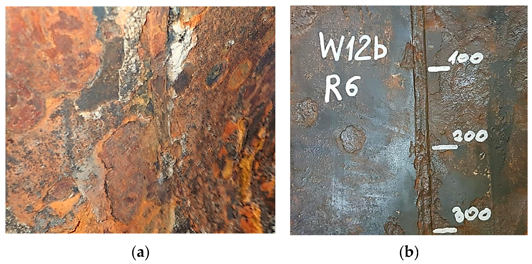
Figure 8.
Water pipe with longitudinal seam – mechanism of selective corrosion formation: 1 – steel pipe shell of the pipeline; 2 - trapped water layer between the pipe material and the layer of corrosion products; 3 – compact, semi-permeable layer of corrosion products and contaminants; 4 – external protective layer; 5 – areas of selective corrosion development along the HAZ of the longitudinal weld; 6 – local pits as a result of selective corrosion; σr – circumferential stresses in the pipe; p – network pressure.
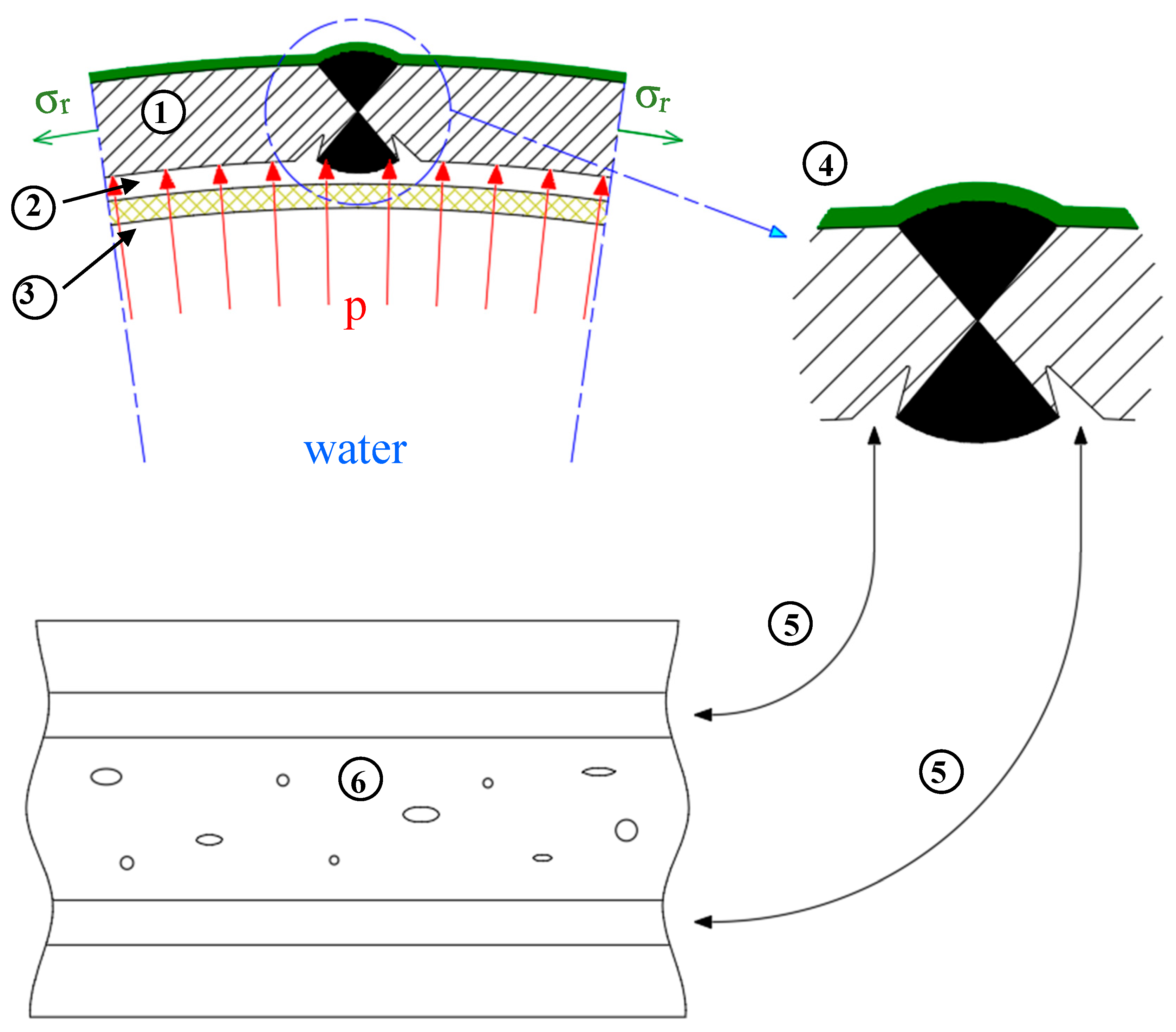
Figure 9.
View of the remaining weld remnants at the edge of the joint with the longitudinal weld of the fractured pipe.
Figure 9.
View of the remaining weld remnants at the edge of the joint with the longitudinal weld of the fractured pipe.
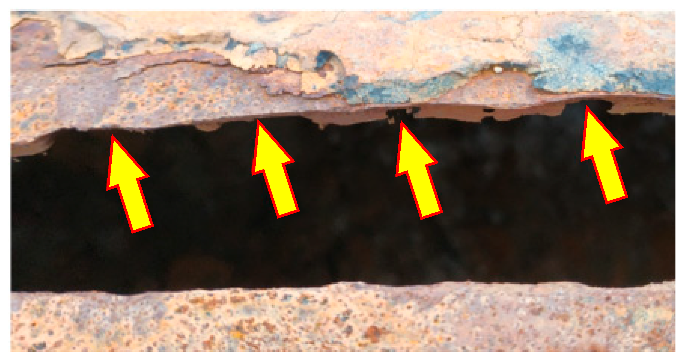
Figure 10.
View of the internal surface of the pipe segment illustrating the degree of weld degradation for water transport pipes.
Figure 10.
View of the internal surface of the pipe segment illustrating the degree of weld degradation for water transport pipes.
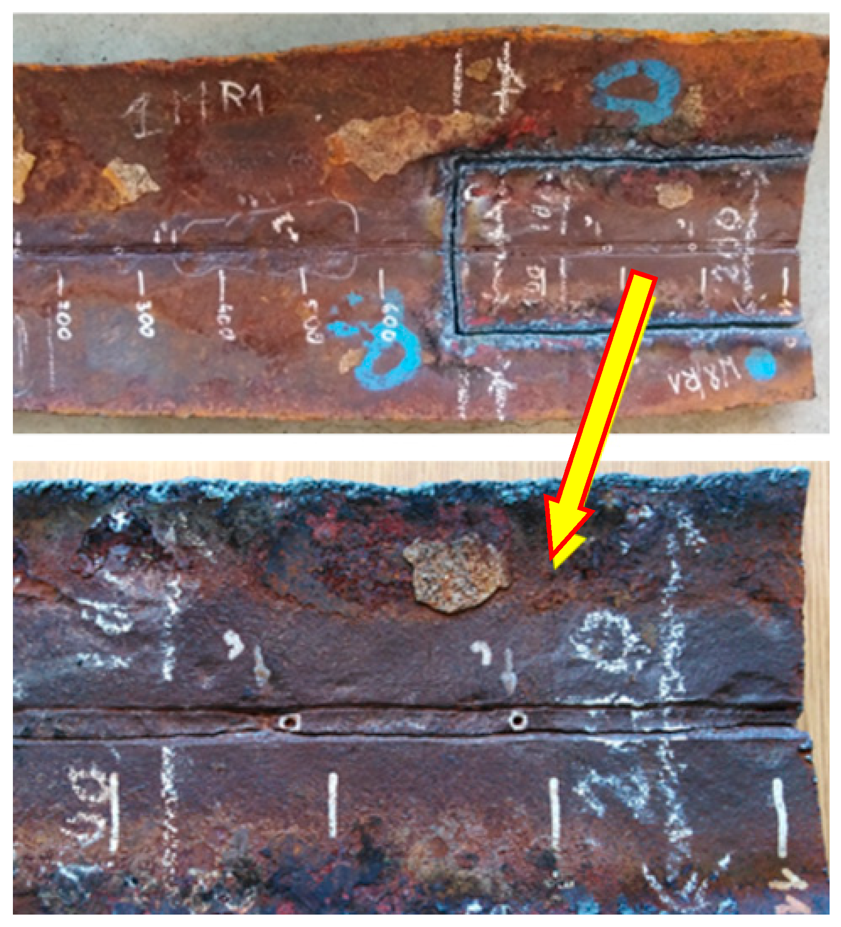
Figure 11.
Division of the pipe segment into samples for macroscopic analysis
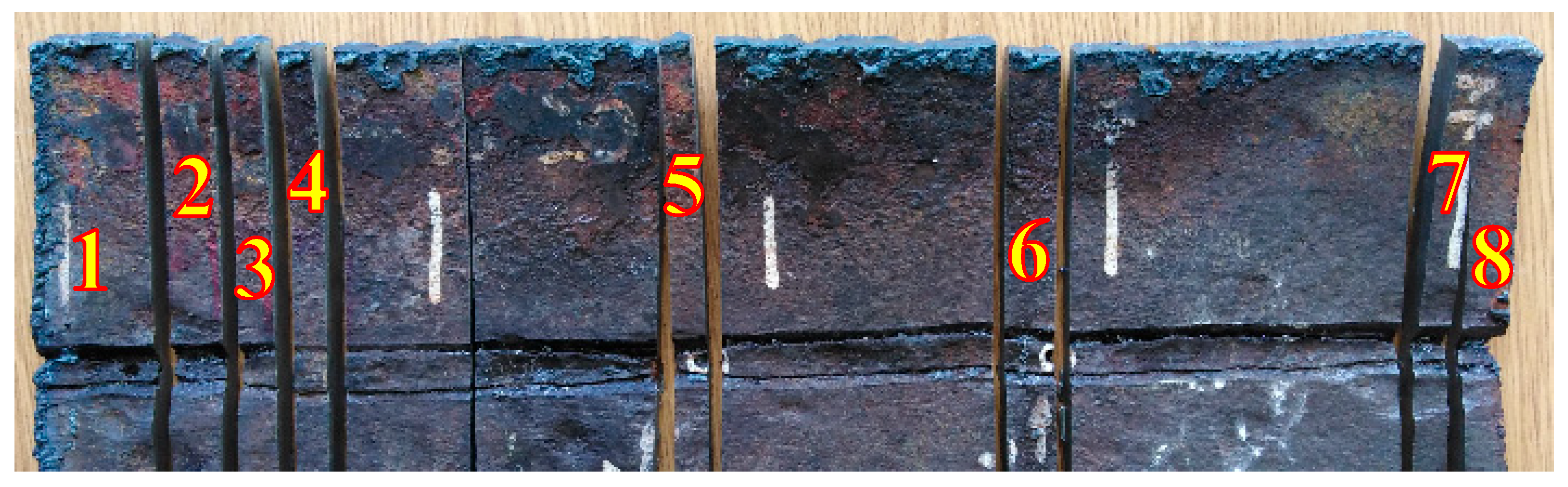
Figure 12.
Macrostructures of Example Welded Joint Samples.
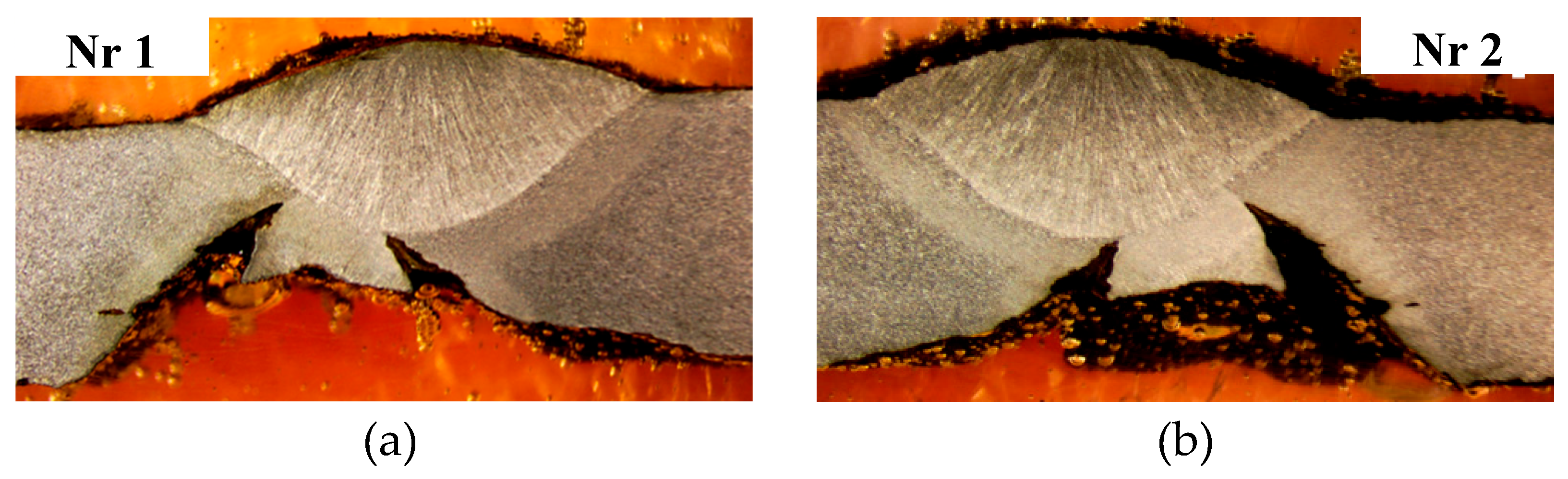
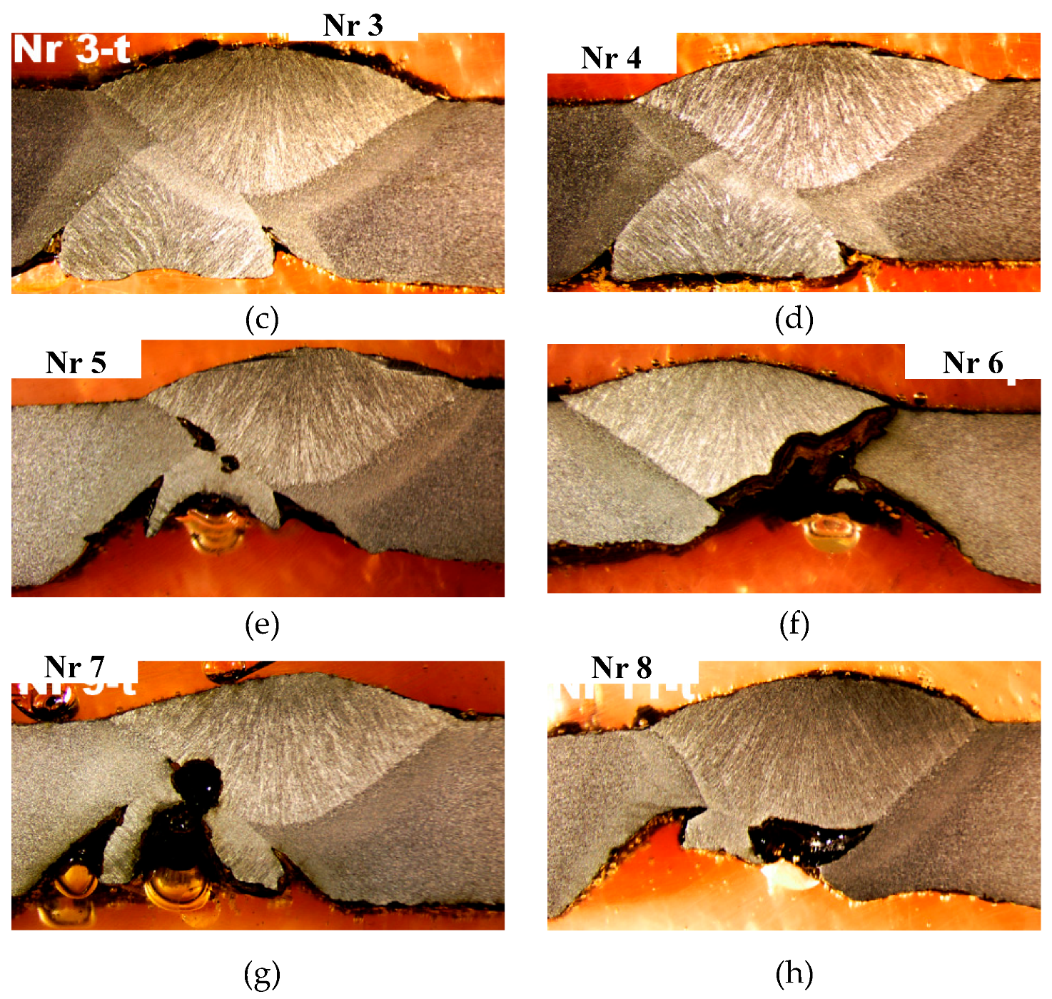
Figure 13.
Anodic Areas (blue) and Cathodic Areas (pink) in the Welded Joints of the Pipe
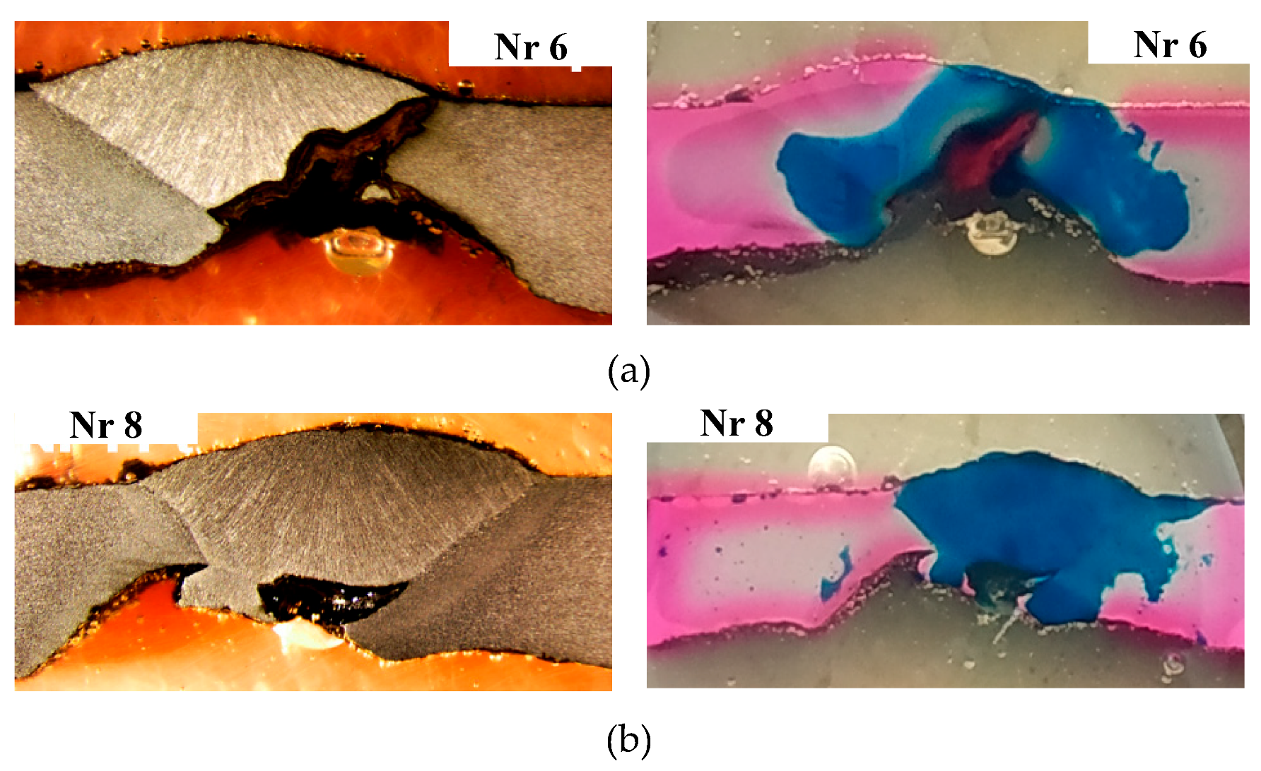
Figure 14.
Potential profile around the base material.
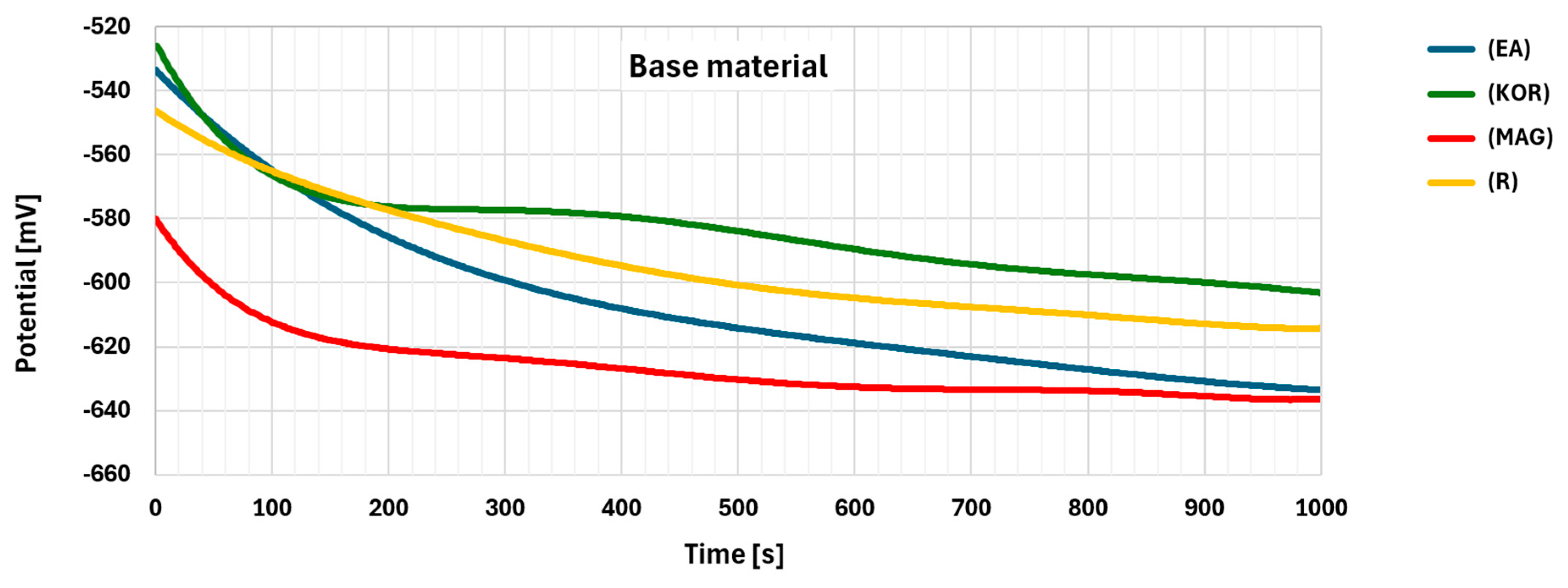
Figure 15.
Potential profile in the heat affected zone (HAZ) area.
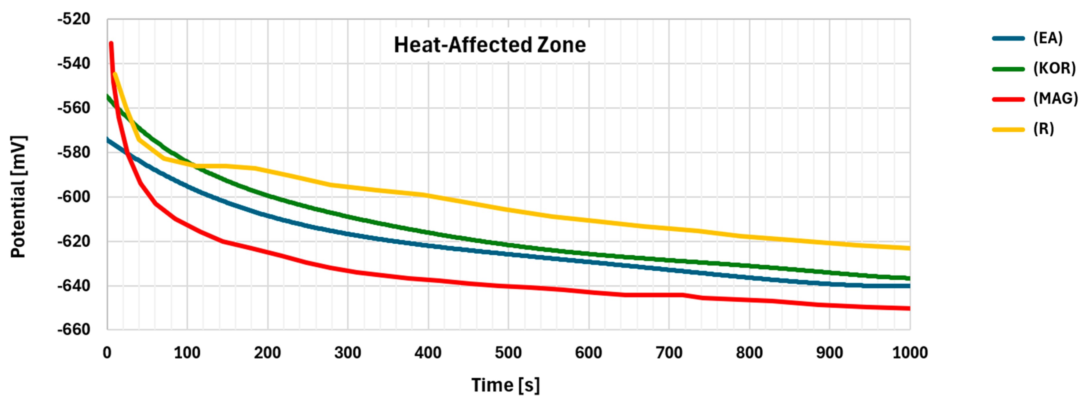
Figure 16.
Potential profile in the weld area.
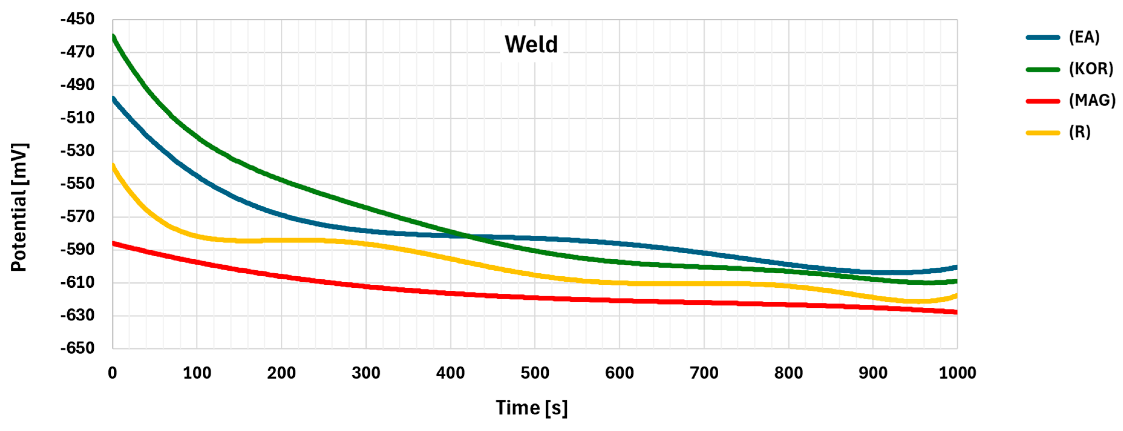
Figure 17.
Microscopic analysis - Pits in HAZ
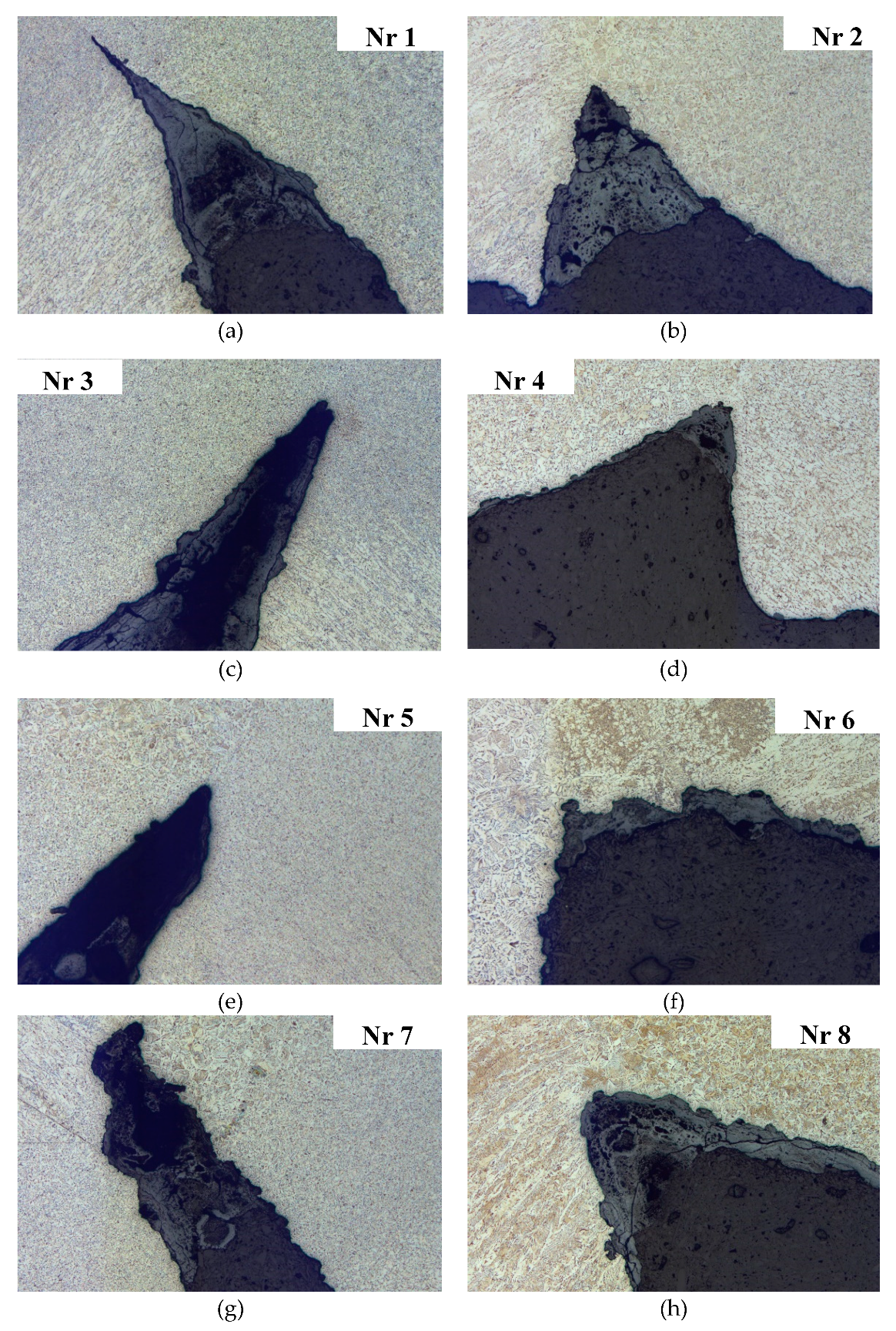
Figure 18.
Selected SSH, SR, and SP sections for testing
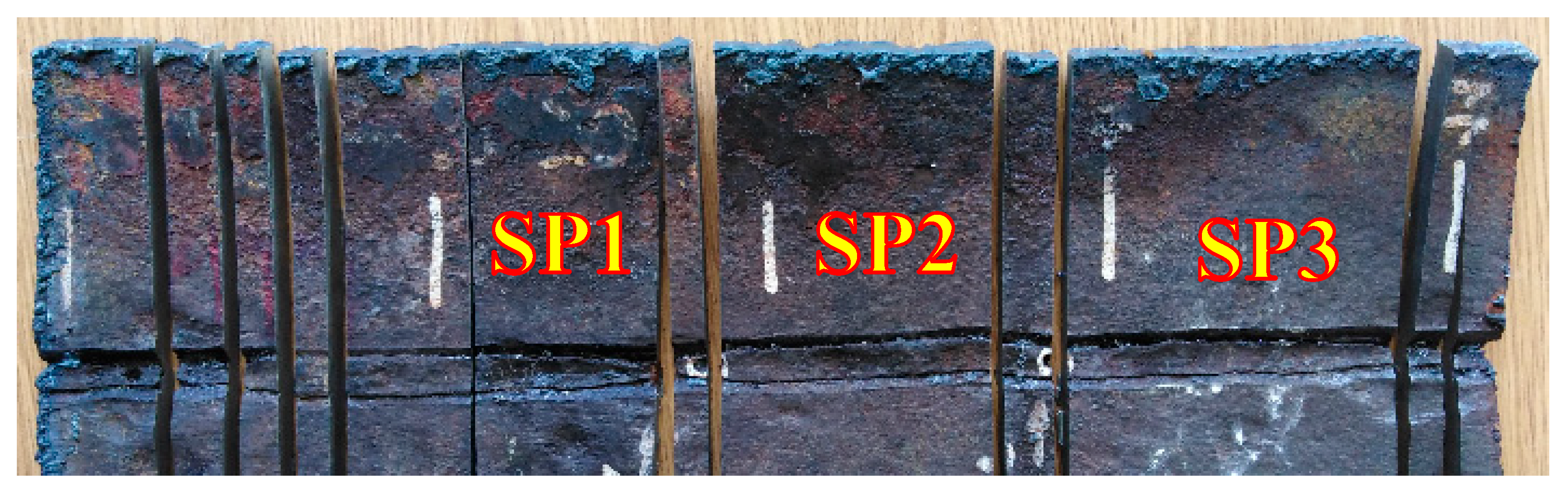
Figure 19.
Samples after strength testing: a – SP1; b – SP2; c – SP3
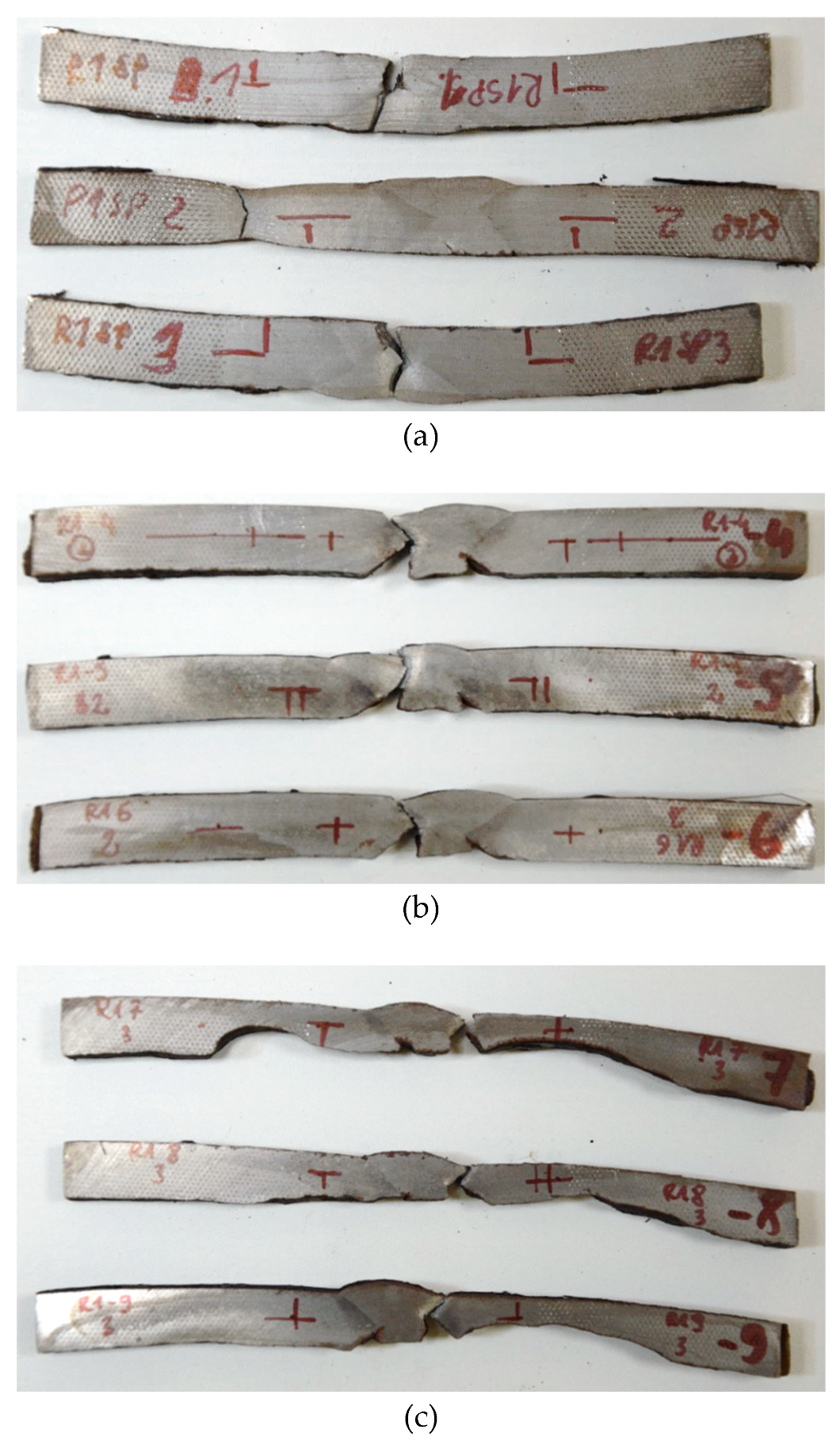
Figure 20.
Tensile curves: a – SP1; b – SP2; c – SP3

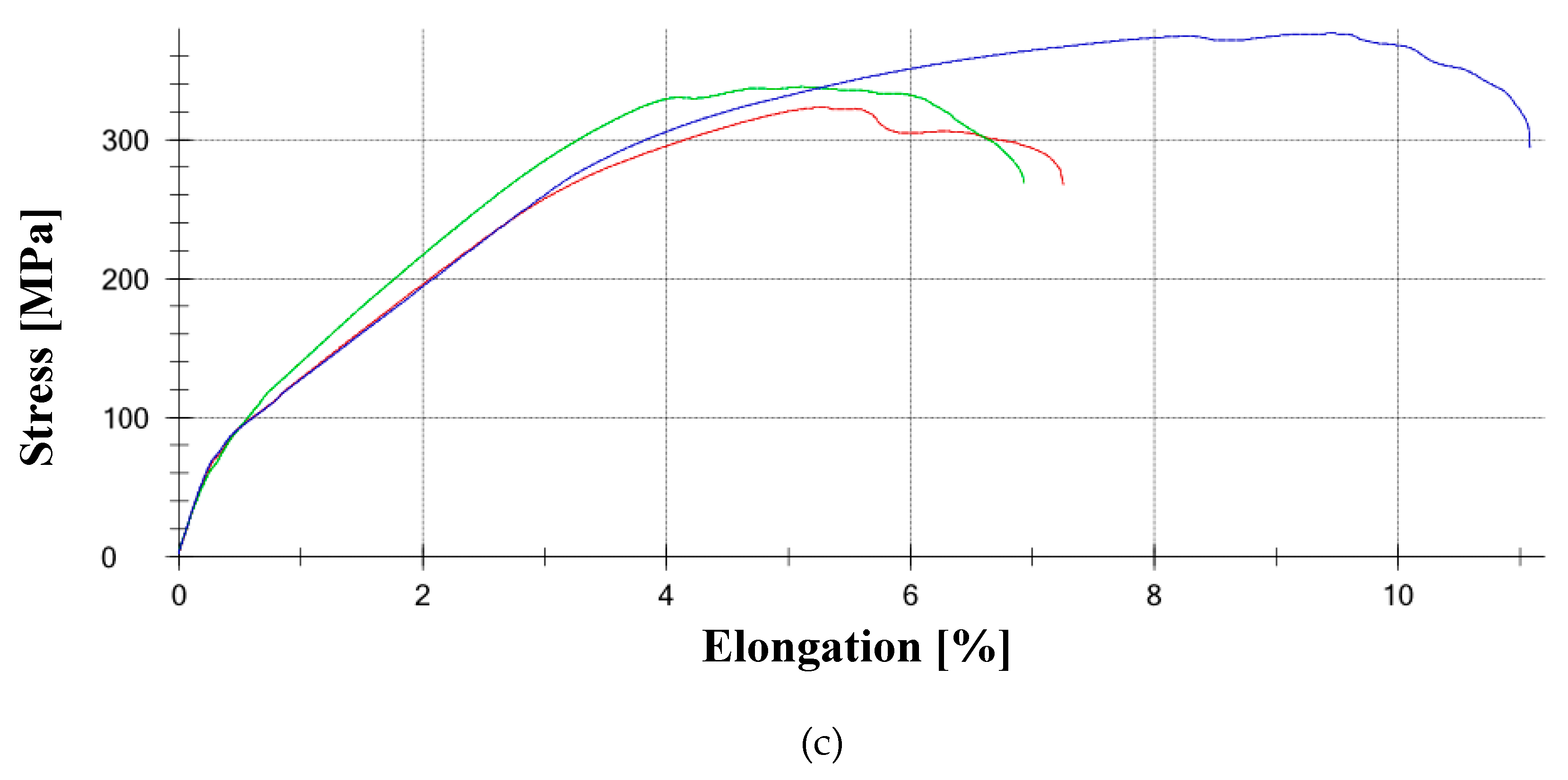
Figure 21.
Schematic for modeling the pipe section and example model dimensions.
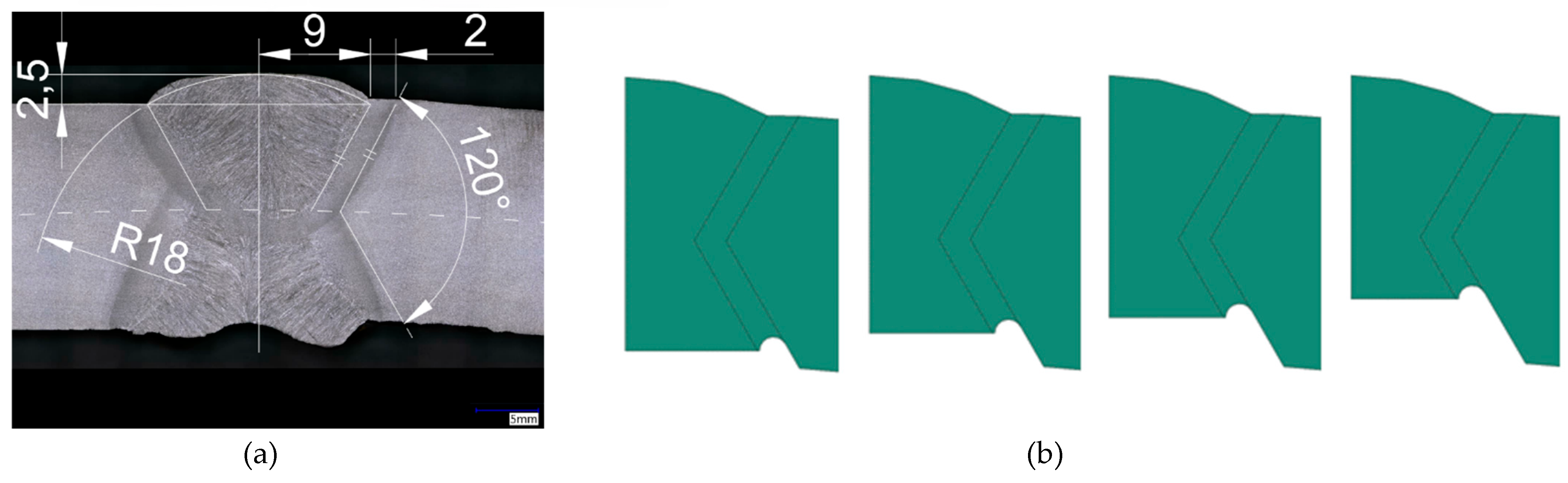
Figure 22.
Circumferential normal stresses [MPa] at a pressure of 16 bar at various levels of longitudinal weld degradation.
Figure 22.
Circumferential normal stresses [MPa] at a pressure of 16 bar at various levels of longitudinal weld degradation.
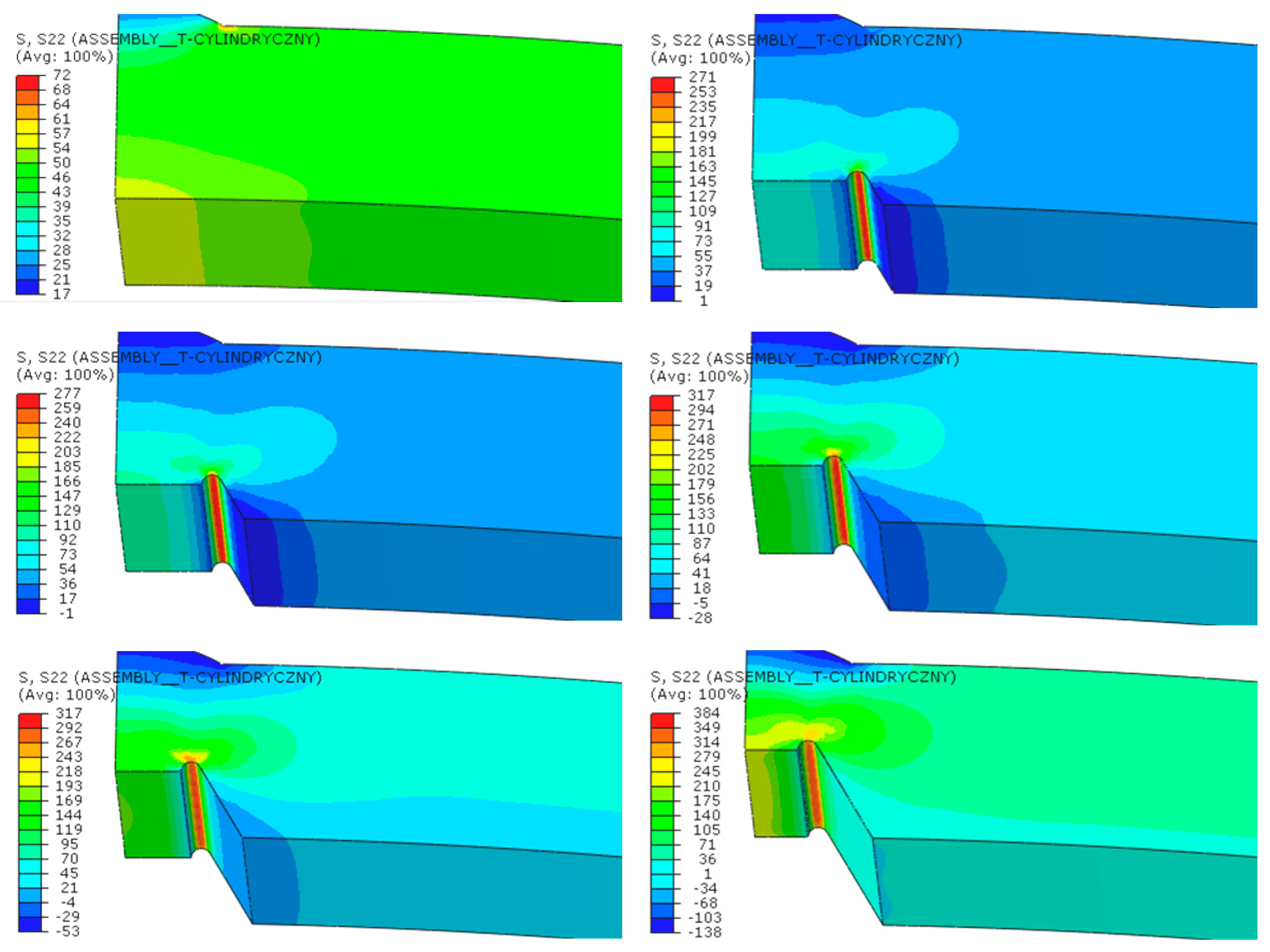
Figure 23.
Equivalent plastic strains in the material at a pressure of 16 bar at various levels of longitudinal weld degradation.
Figure 23.
Equivalent plastic strains in the material at a pressure of 16 bar at various levels of longitudinal weld degradation.
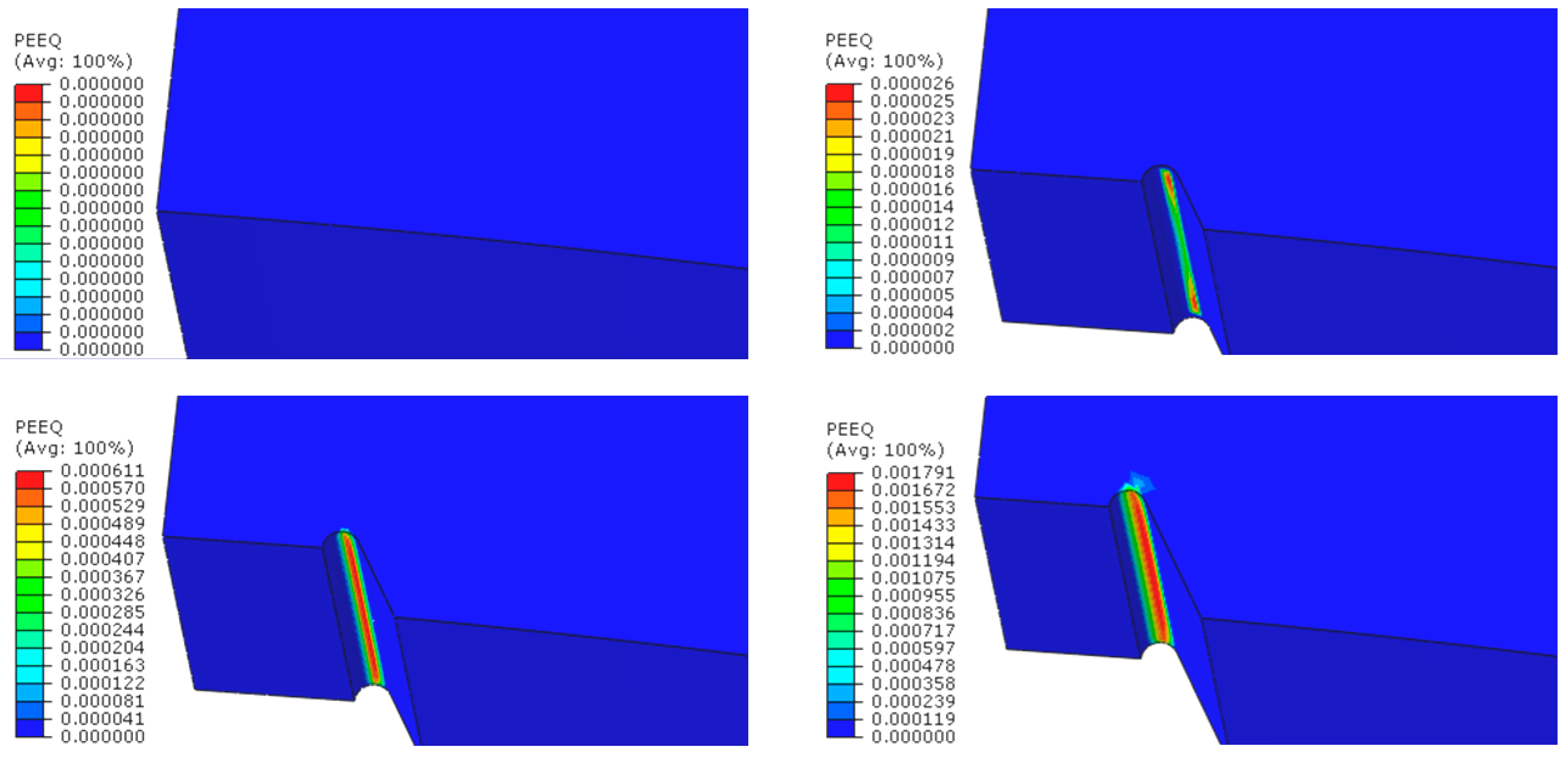
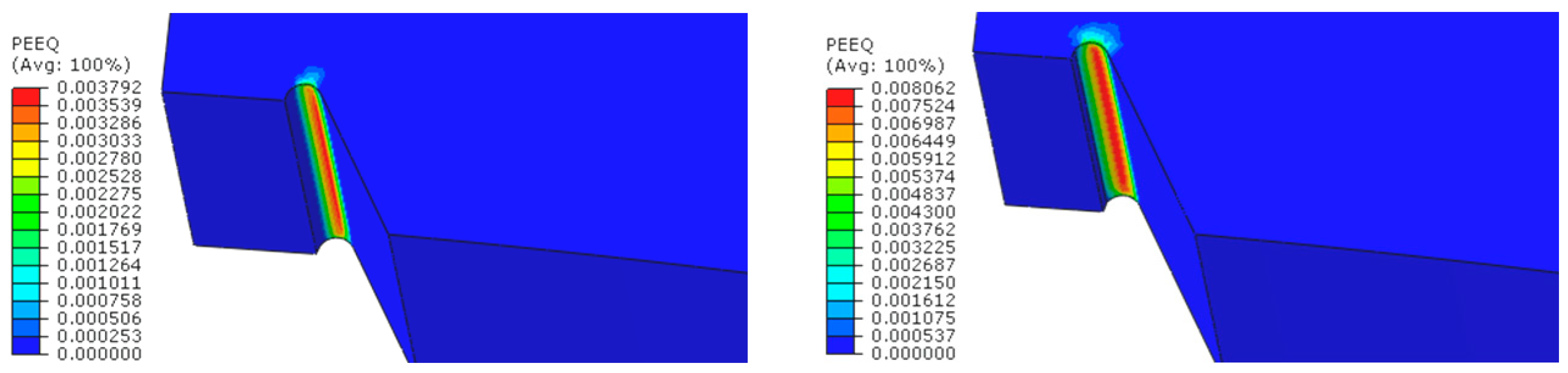
Figure 24.
Sharp termination of the notch bottom in the pit caused by selective corrosion: (a) Dimensions of the model in the second stage of numerical analysis; (b) Discrete model in the pit area during the second stage of numerical analysis.
Figure 24.
Sharp termination of the notch bottom in the pit caused by selective corrosion: (a) Dimensions of the model in the second stage of numerical analysis; (b) Discrete model in the pit area during the second stage of numerical analysis.
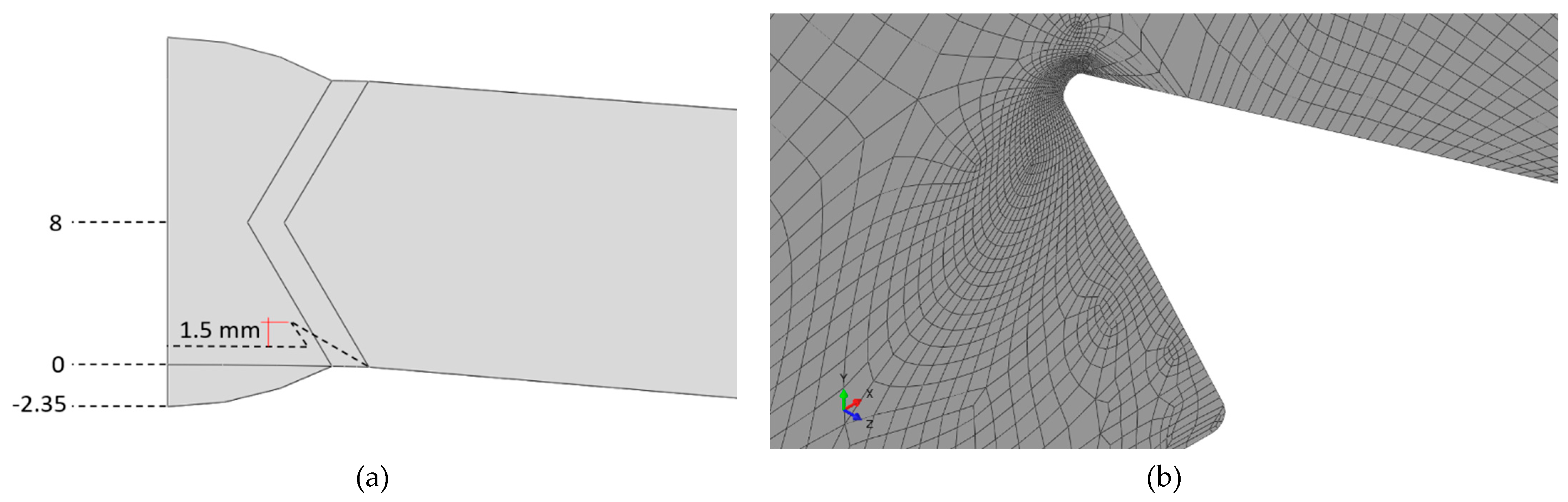
Figure 25.
Results of the numerical analyzes for the second stage: (a) Circumferential normal stress in [MPa] at a pressure of 30 bar and a degradation depth of 6 mm; (b) Equivalent plastic strain at a pressure of 30 bar and a degradation depth of 6 mm.
Figure 25.
Results of the numerical analyzes for the second stage: (a) Circumferential normal stress in [MPa] at a pressure of 30 bar and a degradation depth of 6 mm; (b) Equivalent plastic strain at a pressure of 30 bar and a degradation depth of 6 mm.
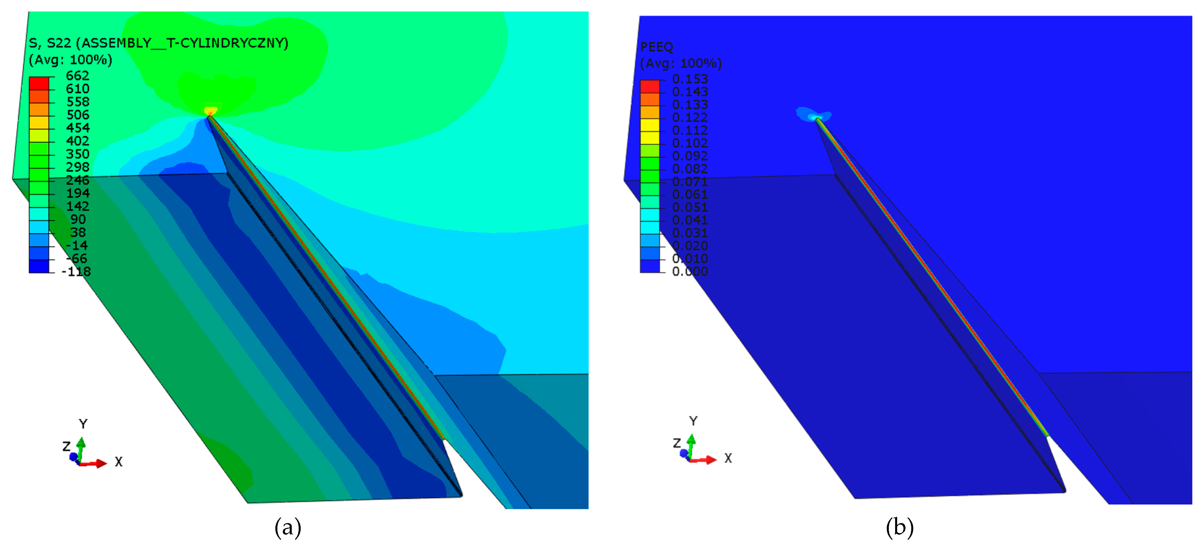
Figure 26.
Plastic deformation as a function of pressure at the bottom of the hole in the longitudinal weld of the pipe, depending on the depth of loss of material.
Figure 26.
Plastic deformation as a function of pressure at the bottom of the hole in the longitudinal weld of the pipe, depending on the depth of loss of material.
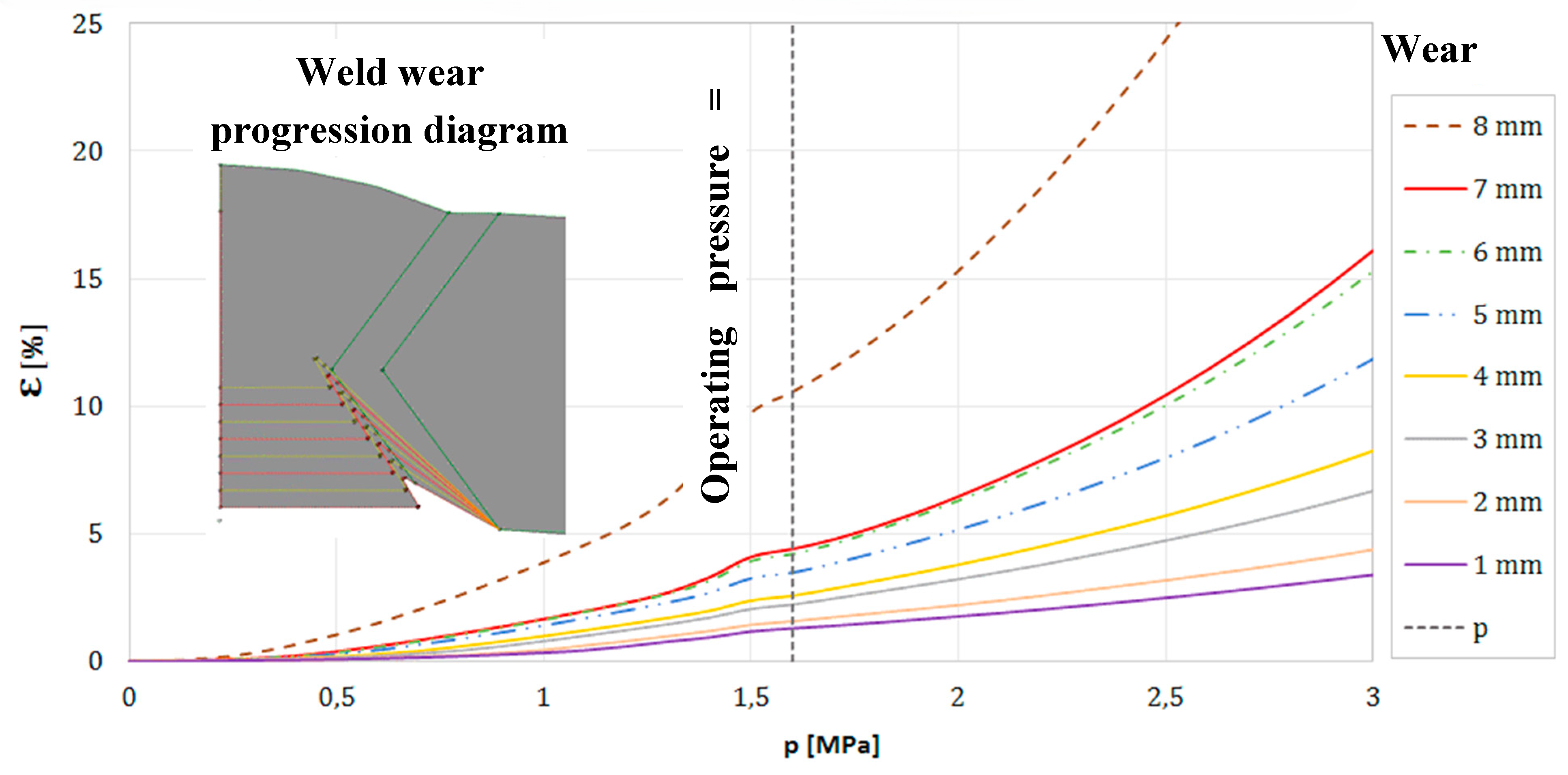

Table 1.
Designations of welded pipe joint samples.
| Sample Identifier | Description |
|---|---|
| EA | Steel samples from the pipe welded with EA electrode |
| COR | Steel samples from the pipe welded with the COR-TEN electrode |
| MAG | Steel samples from the pipe welded using the MAG method |
| R | Original joint from R1 pipe |
Table 2.
Chemical Composition of Weld Metal from Covered Electrodes (EA and COR-TEN)
| Electrode Type | Electrode Classification | Element Content in wt.% | ||||
|---|---|---|---|---|---|---|
| C | Si | Mn | Ni | Cu | ||
| Pipe | Pipe | 0,15 | 0,19 | 0,48 | < 0,01 | 0,013 |
| Acidic | EA 146 | 0,07 | 0,1 | 1,0 | - | - |
| Cor-ten | Tencord 74 Kb | 0,06 | 0,40 | 1,0 | 1,0 | 0,45 |
Table 3.
Values of the Steady-State Potential of Tested Samples after 1000 s in Process Water
| Sample | Weld area [mV] | HAZ [mV] | Base material [mV] |
|---|---|---|---|
| EA | -604,91 | -643,45 | -635,09 |
| COR | -609,54 | -636,34 | -603,11 |
| MAG | -627,17 | -650,37 | -636,73 |
| R | -619,43 | -624,03 | -615,86 |
Table 4.
Strength Properties for Individual Tensile Tests
| Sample | Rp0,2 | ReH | ReL | Rm | Fm | A5,65 | L0 | a0 | b0 | S0 |
| MPa | MPa | MPa | MPa | kN | % | mm | mm | mm | mm2 | |
| SP1 - 1 | - | - | - | 352 | 21,44 | - | - | 5,86 | 10,40 | 60,94 |
| SP1 - 2 | - | - | - | 440 | 26,24 | - | - | 5,84 | 10,22 | 59,68 |
| SP1 - 3 | - | - | - | 388 | 23,14 | - | - | 5,83 | 10,24 | 59,70 |
| SP2 - 4 | - | - | - | 348 | 19,46 | - | - | 7,25 | 7,71 | 55,90 |
| SP2 - 5 | - | - | - | 413 | 22,88 | - | - | 7,25 | 7,65 | 55,46 |
| SP2 - 6 | - | - | - | 386 | 18,95 | - | - | 7,25 | 6,77 | 49,08 |
| SP3 - 7 | - | - | - | 323 | 10,82 | - | - | 7,68 | 4,36 | 33,48 |
| SP3 - 8 | - | - | - | 338 | 9,66 | - | - | 6,60 | 4,33 | 28,58 |
| SP3 - 9 | - | - | - | 376 | 13,59 | - | - | 7,67 | 4,71 | 36,13 |
Disclaimer/Publisher’s Note: The statements, opinions and data contained in all publications are solely those of the individual author(s) and contributor(s) and not of MDPI and/or the editor(s). MDPI and/or the editor(s) disclaim responsibility for any injury to people or property resulting from any ideas, methods, instructions or products referred to in the content. |
© 2024 by the authors. Licensee MDPI, Basel, Switzerland. This article is an open access article distributed under the terms and conditions of the Creative Commons Attribution (CC BY) license (http://creativecommons.org/licenses/by/4.0/).
Copyright: This open access article is published under a Creative Commons CC BY 4.0 license, which permit the free download, distribution, and reuse, provided that the author and preprint are cited in any reuse.


