Introduction
Abdominal wall hernias are a common condition associated with significant morbidity and complications. Despite numerous surgical techniques, there is no consensus on a gold standard for hernia repair. Many current treatment strategies fail to address the underlying pathophysiology and disrupt the natural dynamics of the abdominal wall.
Conventional hernia repair primarily relies on flat meshes designed to "reinforce" the abdominal wall by covering the hernia defect. However, these static and passive meshes present several limitations:
They do not replicate the dynamic function of abdominal musculature, requiring fixation that exacerbates postoperative pain, impairs movement, and results in unphysiological outcomes. [
1,
2,
3,
4]
They elicit stiff, fibrotic foreign body granulomas [
5,
6,
7,
8,
9], which fail to address the degenerative origins of hernia disease, such as the chronic compressive damage to the abdominal wall musculature commonly observed in inguinal hernias. [
10,
11,
12,
13,
14]
The hernia defect often remains patent post-repair, increasing the risk of recurrence. [
15]
Placement typically necessitates extensive tissue dissection, raising the risk of iatrogenic injuries, edema, and delayed recovery.
An optimal hernia repair approach should avoid fixation to respect abdominal wall physiology, promote tissue regeneration to restore the muscular barrier, achieve permanent defect obliteration to prevent recurrence, and simplify the procedure to eliminate extensive tissue dissection and trauma.
To meet these requirements, the Stenting & Shielding (S&S) Hernia System was developed to:
Provide fixation-free deployment without tissue dissection.
Permanently obliterate the hernia defect.
Assure dynamic compliance with abdominal wall movements.
Act as a regenerative scaffold, promoting the development of newly formed connective tissue, muscles, vessels, and nerves to restore the integrity of the abdominal wall barrier.
An additional requirement for this new concept was the development of a surgical technique with the shortest possible learning curve, making the approach feasible in all clinical settings.
The device, fabricated from medical-grade polypropylene-based thermoplastic elastomer (TPE), was inspired by cardiovascular stents. Upon deployment, its stent-like component transforms into a dynamic 3D scaffold that adapts to abdominal wall movements fostering a probiotic biological response. An oval shield stabilizes the scaffold and protects against future herniation near the primary defect.
This study presents the results of an experimental trial of the S&S Hernia System in a porcine model, where 20 devices were implanted in 10 pigs and evaluated at defined postoperative intervals.
Material and Methods
Ethical Approval and Study Design
The experimental trial was conducted in compliance with the Animal Care Protocol for Experimental Surgery, authorized by the Italian Ministry of Health (Decree No. 379/2021-PR, June 1, 2021). The work has been reported in accordance with the ARRIVE guidelines (Animals in Research: Reporting In Vivo Experiments). [
16]
From February 2022 to November 2024, 10 female pigs (4–6 months old, 40–60 kg) underwent laparoscopic intraabdominal implantation of two Stenting & Shielding (S&S) Hernia Devices. Procedures were performed under general anesthesia (zolazepam + tiletamine 6.3 mg/kg + xylazine 2.3 mg/kg; induction: propofol 0.5 mg/kg; maintenance: isoflurane + pancuronium 0.07 mg/kg). Postoperative care included oxytetracycline (20 mg/kg/day for 3 days).
Stenting & Shielding Hernia System: Design and Function
The S&S Hernia System, composed of medical-grade polypropylene-based thermoplastic elastomer (TPE), whose technical properties are highlighted in
Table 1.
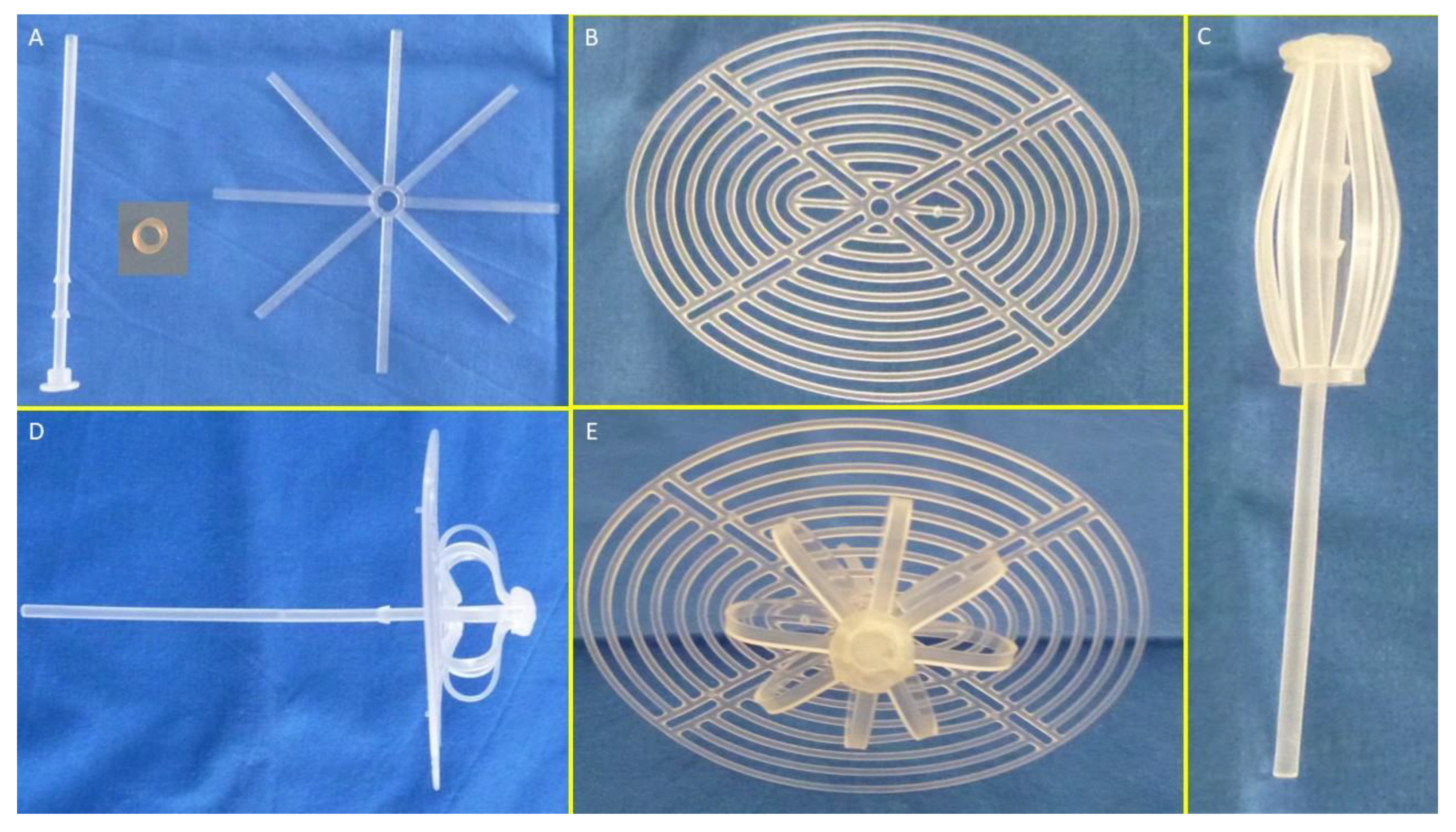
The S&S device is designed for permanent defect obliteration. Its components include:
Mast element: Equipped with a button-like distal end and two conic stops.
Rayed structure: Eight rays connected by a central ring.
Assembly ring: Secures the mast and rayed structure.
3D oval shield plate: Dimensions: 10×8 cm; central ring for attachment.
Figure 1A,B show the components of the device.
Operational Steps
- 1.
Assembly and Preparation:
- ○
The mast, rayed structure, and assembly ring are assembled into a cylindrical compound. (
Figure 1 C)
- ○
The shield plate is loosely attached to the mast for laparoscopic delivery.
- ○
The conic enlargements of the mast that serve as stops, secure the shield and the 3D scaffold in its final position preventing the shield from slipping backwards. (
Figure 1 D – E)
- ○
The prepared device, held by the forceps inserted in the metallic tube, is intended to be introduced into a trocar channel to be delivered into the abdominal cavity. (
Figure 2 A – E)
- 2.
Deployment:
- ○
All procedures are planned to be performed laparoscopically.
- ○
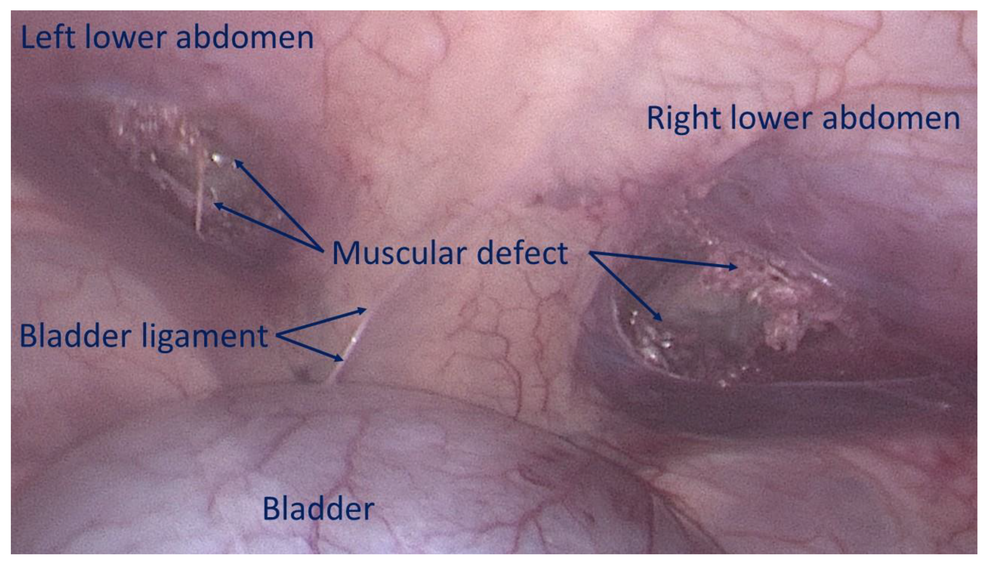
The first step involves creating a defect in the lower abdominal wall musculature of the pig. Depending on the anatomical aspect of the swine, the defects were made using electrocautery bilaterally either in the lower part of the rectus muscle or in the lower medial aspect of the lateral abdominal musculature to achieve a ca. 3,5 cm wide opening. (
Figure 3)
- ○
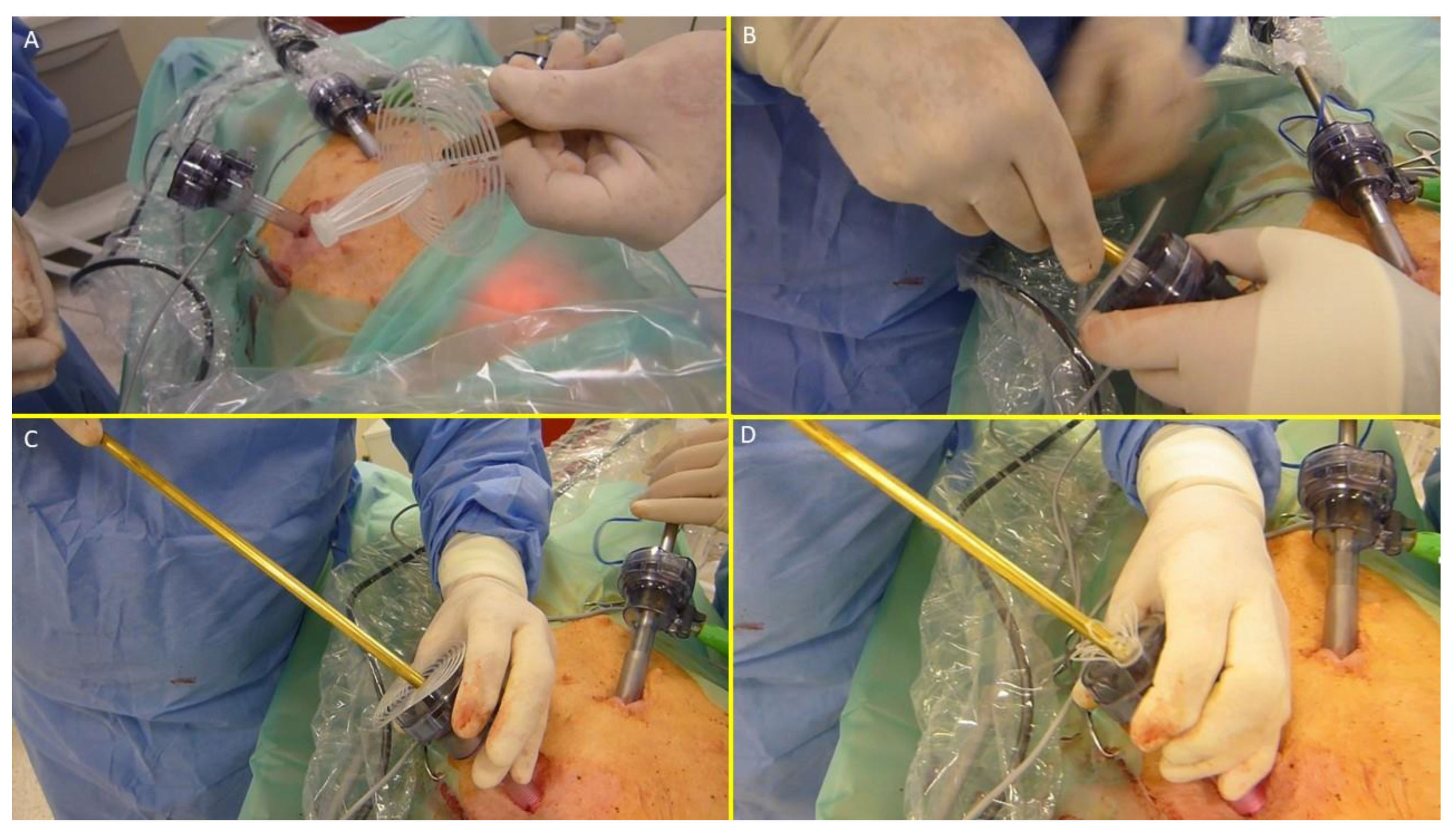
The device was compounded by inserting the grip of a laparoscopic forceps into an 8 mm metallic tube. Additionally, the branches of the forceps firmly held the mast of the 3D scaffold in a restrained mode along with the loose shield. (
Figure 4A)
- ○
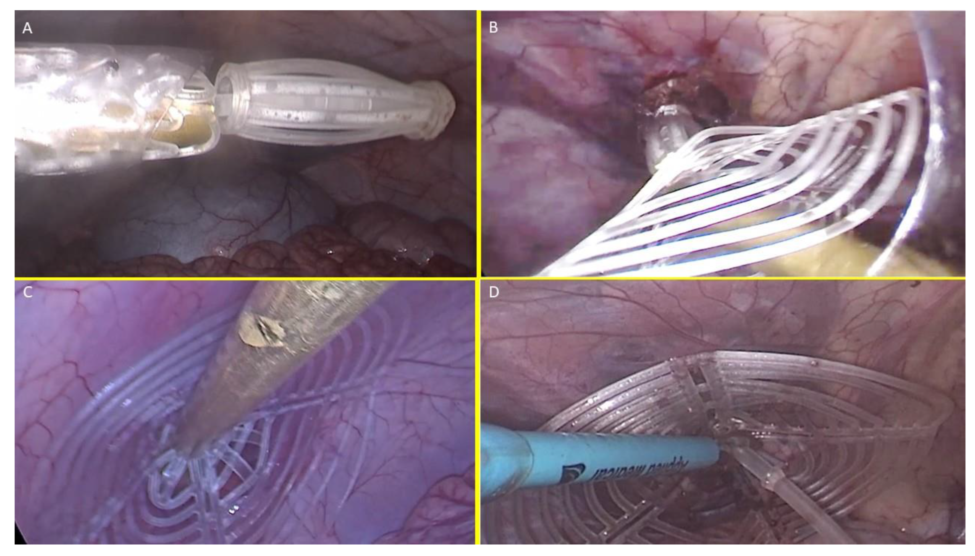
With this configuration, the S&S device was delivered through a 12 mm trocar into the abdominal cavity (
Figure 4B, C, D,
Figure 5A),
- ○
At this stage the device is approached and introduced into the defect. (
Figure 5B)
- ○
Then, with a combined maneuver, the metallic tube was pushed to slide the shield forward along the central mast while simultaneously the forceps pulled the proximal edge of the mast backward. This allowed the shield to surpass the two conic stops of the mast
- 3.
Securing the Device:
- ○
The conic stops lock the shield in position. Adjustments allow tailored scaffold expansion at discretion of the surgeons. (
Figure 5C)
- ○
The redundant mast is excised after confirming stability (
Figure 5D).
Two S&S devices were implanted in each pig, with final configurations shown in
Figure 6. Further detals on design and function of the S&S device as well as operational steps and implantation procedure are highlighted in video 1.
Follow-Up Protocol
Euthanasia and follow-up evaluations were planned as follows:
Short-term (1 month): 2 pigs.
Midterm (3–4 months): 3 pigs.
Long-term (5–8 months): 5 pigs.
Controls included ultrasound and laparoscopic evaluations of the device for positional stability, shield integration, and absence of adhesions to abdominal viscera. Euthanized animals underwent laparotomy for macroscopic assessment and en bloc removal of the S&S device for histological and immunohistochemical analysis.
Histological and Immunohistochemical Study
Excised devices were fixed in 10% neutral buffered formalin and sectioned for histological analysis using Hematoxylin-Eosin (H&E) and Azan-Mallory trichrome staining (Bio-Optica Milano, Italy). Key features examined included inflammatory response, vascularization, and documentation of the ingrown tissue.
Immunohistochemistry assessed growth factors and specialized tissue development:
Neo-neurogenesis: NSE (Neuron-specific Enolase, 1:100, LSBio, USA).
Neo-angiogenesis: VEGF (1:50, R&D Systems, USA); PECAM-1 (CD31, 1:50, Dako-Agilent, USA).
Vascular maturity: SMA (Smooth Muscle Actin, 1:100, Dako-Agilent, USA).
Neomyogenesis: NGF (1:100, Abcam, USA).
Neurogenesis markers: NGFRp75 (1:100, Santa Cruz Biotechnology, USA).
Endpoints
The study endpoints were classified into two arms:
- ○
Feasibility of laparoscopic delivery without tissue dissection.
- ○
Time required for deployment.
- ○
Learning curve for optimal procedure time.
- ○
Device retention within the defect.
- ○
Ultrasound-documented tissue incorporation.
- ○
Laparoscopic evidence of presence/absence of visceral adhesions.
- ○
Macroscopic ingrowth within the 3D scaffold.
- ○
Histological evaluation of tissue integration and inflammatory response.
- ○
Immunohistochemical detection of growth factors (e.g., VEGF, NGF) supporting vascular, muscular, and neural regeneration.
Results
Outcomes of the Surgical Procedure
All procedures were performed without intraoperative complications. Following the creation of bilateral muscular defects in the lower abdomen, no further dissection or additional trauma inside the abdominal cavity was necessary. The S&S devices were delivered through a 12 mm trocar using the proprietary tool that safely guided the device to the defect site. The combined maneuver to position and expand the device within the defect proved to be simple and uncomplicated, allowing the 3D scaffold to be securely fixed according to the procedural plan.
Initially, the delivery and placement process took 3–6 minutes, from trocar introduction to final adjustment. However, starting with the 7th implantation attempt, the time decreased significantly, averaging 1 minute per deployment.
Surgical Follow-Up
All animals, except one, survived until their planned explantation dates. One pig, which succumbed to intestinal occlusion caused by fecaloma 4 weeks postoperatively, underwent immediate autopsy. Both S&S devices in this animal were firmly in place without dislodgement or visceral adhesions, and they were processed per protocol. The deceased pig was included among the two animals scheduled for short-term sacrifice (1 month).
Ultrasound and laparoscopic controls during follow-up confirmed that all devices remained in their original positions without migration. Interaction between the shield and abdominal viscera showed no adhesions in any animals (
Figure 7), except for transient, thin adhesions observed in two animals during the one-month control (
Figure 8 A). These adhesions resolved completely by the three-month follow-up (
Figure 8 B). Substantially, at the time of sacrifice, no adhesions between the shield and abdominal viscera were observed in any animals.
Macroscopic Assessment at Euthanasia
Laparoscopic assessments prior to sacrifice showed that all shields were covered by healthy mesothelium (
Figure 7). Following explantation, the S&S devices were meticulously scarified to remove host native tissue from their boundaries to allow macroscopic evaluation. The excised scaffolds retrieved after 6 months or longer were found to be incorporated with newly developed fleshy tissue resembling muscular tissue (
Figure 9). All devices were then sent for histological examination.
Histological Evidences
Inflammatory Response
Histological analysis with HE staining revealed minimal inflammatory reactions in the early postoperative stage, characterized by limited lymphocytic and histiocytic elements (
Figure 10 A). No more inflammation towards the S&S fabric was detected in mid, long, or long term stages (
Figure 10 B, C).
Neoangiogenesis
Vascular development began early, with newly formed vessels observed within the 3D scaffold (
Figure 10 A). Immature arteries and veins were evident in the short term, progressing structurally in the midterm (
Figure 10 B) and achieving full development in the long term (
Figure 10 C).
Connective Tissue and Neomyogenesis
Azan Mallory trichrome staining demonstrated progressive incorporation of connective and muscular tissue. Initial development was observed early, with significant maturation by the midterm. In the long term, myocytes were fully developed within well-hydrated connective tissue while the muscle bundles exhibited complete structural maturity (
Figure 10 D &
Figure 11 A).
Neonervegenesis
Neo-neurogenic activity was detected early using NSE staining, revealing in the early stages the presence of immature nervous clusters. These clusters developed progressively in the midterm (
Figure 11 B), achieving in the long-term full structural maturity with nervous bundles resembling the typical human nerve architecture (
Figure 11 C).
Immunohistochemical Growth Factor Detection
Vascular Growth Factors: Early VEGF-induced neovascularization (
Figure 11 D) transitioned to a predominance of CD31-positive endothelial cells in the midterm, along with SMA-driven vascular maturation (
Figure 12 A). Long-term specimens exhibited further SMA-mediated structural thickening, with complete vascular development (
Figure 12 B).
Muscular Growth Factors: NGF-positive elements indicated muscular development in the early stage, increasing in quantity and organization into bundles by the mid and long term (
Figure 12 C).
Nervous Growth Factors: NGFRp75-positive neural elements were initially sparse, correlating with immature nervous clusters. By the midterm, these elements increased, showing progressive myelin sheath development. Long-term specimens revealed mature nerve structures resembling human nerves (
Figure 12 D).
Discussion
Abdominal wall hernia repair primarily relies on flat meshes, which, while effective in reinforcing weakened abdominal wall, have
The Stenting & Shielding (S&S) Hernia System was developed to address the typical challenges of conventional hernia repair by streamlining the procedure and promoting better outcomes. Its fixation-free design eliminates the need for sutures or tacks, reducing operative complexity and associated complications. Key features of the S&S device include: some limitations. Actually, static hernia meshes provoke a granulomatous foreign body response that shrinks and hardens its fabric. [
17,
18,
19,
20,
21,
22]. To prevent dislodgement flat meshes require fixation but, especially if sutures or tacks are applied, fixation hinders the muscular movements and introduces risks such as tissue tearing, bleeding, hematoma formation, or mesh detachment, significantly increasing recurrence risks if dislodgment occurs. [
23,
27]
Minimally invasive laparoscopic delivery without tissue dissection.
Permanent obliteration of the hernia defect to prevent recurrence.
An intraabdominal shield protecting neighboring areas from future herniation.
Dynamic compliance with abdominal wall movements, preventing visceral adhesions and fostering regeneration.
Inspired by vascular stents [
28,
29], the device transforms from a cylindrical assembly into a 3D scaffold that fills the defect and is secured by an oval shield. The medical-grade polypropylene-based thermoplastic elastomer (TPE) ensures elasticity, durability, and adaptability to muscle movements without breaking. Unlike conventional flat meshes, the S&S scaffold induces a probiotic biological response, leveraging its dynamic properties to foster tissue regeneration, including the formation of new muscle fibers, vascular elements, and nerves. This dynamic regeneration, as observed in other dynamic responsive scaffolds for hernia repair, seems to actively restore the integrity of the abdominal wall barrier while addressing the degenerative mechanisms underlying hernia disease [
30,
31].
Adhesion formation, a common complication with static meshes, can lead to bowel obstruction and other issues. Flat meshes placed intraperitoneally are particularly prone to adhesions due to their passive nature [
32,
33].
To address this, the S&S device employs TPE, a biocompatible material that transmits dynamic forces from abdominal wall movements to the shield, preventing the development of adhesion bridles. Preliminary experimental testing identified TPE as the optimal material due to its unique combination of elasticity and anti-adhesive properties, outperforming other tested substances, including polypropylene, polyester, and polyurethane.
The study demonstrated the secure retention of all 20 implanted S&S devices, with no migration or dislocation observed. Importantly, no adhesions between the shield and visceral organs were detected at animal euthanasia, underscoring the biocompatibility of TPE and the role of dynamic compliance in adhesion prevention.
Macroscopic evaluations revealed the scaffold filled with newly formed tissue (
Figure 9), contrasting with the fibrotic response typical of conventional meshes. Histological analyses confirmed minimal inflammation, limited to the early period, and robust regeneration, with connective tissue, muscle fibers, nerves, and blood vessels progressively developing into the scaffold. Immunohistochemistry further highlighted growth factors (e.g., VEGF, CD31, SMA, NGF, NGFRp75) driving vascularization, myogenesis, and neural regeneration, demonstrating a probiotic biological response not observed in static mesh repairs. This final feature provides additional evidence that the S&S device can effectively promote regeneration and re-establish the integrity of the muscular barrier. This property aligns perfectly with the goals of a device designed to address a degenerative condition such as an abdominal wall hernia.
Conclusions
This study highlights the potential of the Stenting & Shielding (S&S) Hernia System in providing efficient, minimally invasive hernia repair. However, some limitations must be acknowledged. First, the sample size of 10 pigs with 20 implanted devices limits statistical power and generalizability. While this aligns with similar preclinical safety and efficacy studies [
17], resource constraints —particularly the costs associated with long-term animal care— required careful budget management.
Second, the study did not include direct comparisons with conventional hernia repair techniques, such as tension-free hernioplasty or laparoscopic mesh repair. Future randomized controlled trials in humans are essential to evaluate the S&S system's comparative advantages and broader clinical applicability.
Finally, this report focuses on the surgical and basic regenerative aspects of the device. A more comprehensive histological and immunohistochemical analysis will be detailed in subsequent publications to provide deeper insights into the biological mechanisms underlying the device’s performance.
Despite these limitations, the S&S Hernia System likely demonstrated notable efficacy and safety in this preclinical study. The device’s innovative design and material properties facilitated a fixation-free, dynamically responsive solution for defect obliteration, eliminating the risk of visceral adhesions and promoting tissue regeneration. The minimally invasive approach, requiring no surgical dissection, resulted in an intuitive, swift and easily reproducible procedure.
These findings suggest that the S&S system could manage various hernia types—including inguinal, femoral, Spigelian, obturator, and incisional hernias—without the trauma associated with conventional techniques. By inducing true regeneration of connective tissue, muscles, vessels, and nerves, the S&S scaffold addresses the physiological, structural and biological deficiencies of conventional hernia repair methods. This regenerative capability ensures not only defect closure but also restoration of the abdominal wall's functional integrity. If validated in human trials, this system could redefine hernia repair by offering a simplified repair concept rooted in pathophysiology and regeneration rather than reinforcement alone.
Author Contributions
Giuseppe Amato Conceptualization, Writing the manuscript; Giorgio Romano: Review & Editing. Luca Cicero Methodology, Investigation, Giovanni Cassata: Project administration, Data Curation Giuseppe Di Buono: Resources Giorgio Romano 2nd: review Vito Rodolico: Methodology Roberto Puleio: Conceptualization; Antonino Agrusa: Supervision, All authors have read the final manuscript and approved its submission for publication.
Funding
This research did not receive any specific grant from funding agencies in the public, commercial, or not-for-profit sectors.
Data availability
The datasets used and analyzed during the study are available from the corresponding author upon reasonable request.
Compliance with Ethical Standards
Approval was obtained for this study from Animal Care Protocol for Experimental Surgery issued by the Italian Ministry of Health and authorized by same Ministry of Health with the decree n° 379/2021-PR released on June 1st, 2021.
Human and animal right
Animal experiments have been conducted in compliance with the guidelines of the Animal Care Protocol for Experimental Surgery issued by the Italian Ministry of Health.
Disclosure
Dr. Giuseppe Amato is the developer and patent owner of the device being discussed in the article, the other authors have no conflict of interest to declare
References
- Amato G. State of the art and future perspectives in inguinal hernia repair. In: Inguinal Hernia: Pathophysiology and Genesis of the Disease. Cham: Springer; 2022. p. 143-163. [CrossRef]
- Kingsnorth A, LeBlanc K. Hernias: inguinal and incisional. Lancet. 2003;362:1561-71. [CrossRef]
- LeBlanc KA. Complications associated with the plug-and-patch method of inguinal herniorrhaphy. Hernia. 2001;5(3):135-8. [CrossRef]
- Klosterhalfen B, Klinge U, Schumpelick V. Functional and morphological evaluation of different polypropylene-mesh modifications for abdominal wall repair. Biomaterials. 1998 Dec;19(24):2235-46. [CrossRef]
- Klinge U, Klosterhalfen B, Muller M, Schumpelick V. Foreign body reaction to meshes used for the repair of abdominal wall hernias. Eur J Surg. 1999;65:665-73. [CrossRef]
- O’Dwyer PJ, Kingsnorth AN, Mohillo RG, Small PK, Lammers B, Horeyseck G. Randomized clinical trial assessing the impact of a lightweight or heavyweight mesh on chronic pain after inguinal hernia repair. Br J Surg. 2005;92(2):166-70. [CrossRef]
- Weyhe D, Schmitz I, Belyaev O, Grabs R, Müller KM, Uhl W, Zumtobel V. Experimental comparison of monofile light and heavy polypropylene meshes: less weight does not mean less biological response. World J Surg. 2006;30(8):1586-91. [CrossRef]
- Köckerling F, Koch A, Lorenz R, Reinpold W, Hukauf M, SchugPass C. Open repair of primary versus recurrent male unilateral inguinal hernias: perioperative complications and 1-year follow-up. World J Surg. 2016;40(4):813-25. [CrossRef]
- Amato G, Calò PG, Rodolico V, Puleio R, Agrusa A, Gulotta L, Gordini L, Romano G. The septum inguinalis: a clue to hernia genesis? J Invest Surg. 2018;31:1-9.
- Amato G, Marasa L, Sciacchitano T, Bell SG, Romano G, Gioviale MC, Lo Monte AI, Romano M. Histological findings of the internal inguinal ring in patients with indirect inguinal hernia. Hernia. 2009;13:259-62. [CrossRef]
- Amato G, Ober E, Romano G, Salamone G, Agrusa A, Gulotta G, Bussani R. Nerve degeneration in inguinal hernia specimens. Hernia. 2011;15:53-8. [CrossRef]
- Amato G, Romano G, Salamone G, Agrusa A, Saladino VA, Silvestri F, Bussani R. Damage to the vascular structures in inguinal hernia specimens. Hernia. 2012;16(1):63-7. [CrossRef]
- Amato G, Agrusa A, Romano G, Salamone G, Gulotta G, Silvestri F, Bussani R. Muscle degeneration in inguinal hernia specimens. Hernia. 2012;16(3):327-31. [CrossRef]
- Amato G, Agrusa A, Romano G, Salamone G, Cocorullo G, Mularo SA, Marasa S, Gulotta G. Histological findings in direct inguinal hernia. Hernia. 2013;17(6):757-63. [CrossRef]
- Amato G, Agrusa A, Di Buono G, Calò PG, Cassata G, Cicero L, Romano G. Inguinal hernia: defect obliteration with the 3D dynamic regenerative scaffold Proflor™. Surg Technol Int. 2021;38:199-205. [CrossRef]
- Kilkenny C, Browne WJ, Cuthill IC, Emerson M, Altman DG. Improving bioscience research reporting: the ARRIVE guidelines for reporting animal research. PLoS Biol. 2010;8(6):e1000412. doi:10.1371/journal.pbio.1000412. [CrossRef]
- Klosterhalfen B, Klinge U, Schumpelick V. Functional and morphological evaluation of different polypropylene-mesh modifications for abdominal wall repair. Biomaterials. 1998 Dec;19(24):2235-46. [CrossRef]
- Klinge U, Klosterhalfen B, Muller M, Schumpelick V Foreign body reaction to meshes used for the repair of abdominal wall hernias. Eur J Surg 1999;65:665–673. [CrossRef]
- Zwaans WAR, Verhagen T, Wouters L, Loos MJA, Roumen RMH, Scheltinga MRM. Groin Pain Characteristics and Recurrence Rates: Three-year Results of a Randomized Controlled Trial Comparing Self-gripping Progrip Mesh and Sutured Polypropylene Mesh for Open Inguinal Hernia Repair Ann Surg. 2018 Jun;267(6):1028-1033. [CrossRef]
- Weyhe D, Schmitz I, Belyaev O, Grabs R, Müller KM, Uhl W, Zumtobel V. Experimental comparison of mono-file light and heavy polypropylene meshes: less weight does not mean less biological response. World J Surg. 2006;30(8):1586–1591. [CrossRef]
- O’Dwyer PJ, Kingsnorth AN, Mohillo RG, Small PK, Lammers B, Horeysee G. Randomized clinical trial as-sessing impact of a lightweight or heavyweight on chronic pain after inguinal hernia repair. Br J Surg 2005;92:166-70.
- Silvestre AC, de Mathia G B, Fagundes, D J, Medeiros L R, Rosa M I. Shrinkage evaluation of heavyweight and lightweight polypropylene meshes in inguinal hernia repair: a randomized controlled trial. Hernia 2011 Dec;15(6):629-34.
- Schmedt CG, Sauerland S, Bittner R. Comparison of endoscopic procedure vs Progrip and other open mesh techniques for inguinal hernia repair: a meta-analysis of randomized controlled trials. Surg Endosc. 2005;19(2):188-9. [CrossRef]
- Bay-Nielsen M, Nilsson E, Nordin P, Kehlet H; Swedish Hernia Data Base the Danish Hernia Data Base Chronic pain after open mesh and sutured repair of indirect inguinal hernia in young males. Br J Surg 2004;91:1372–1376.
- Mayer F, Niebuhr H, Lechner M, Dinnewitzer A, Köhler G, Hukauf M, Fortelny RH, Bittner R, Köckerling F. When is mesh fixation in TAPP repair of primary inguinal hernia necessary? A register-based analysis of 11,230 cases. Surg Endosc. 2016;30(10):4363-71. [CrossRef]
- Watson JT, Webb DW, Stoikes NFN, Voeller GR. Affiliations expand Fibrin Sealant: A Review of the History, Biomechanics, and Current Applications for Prosthetic Fixation in Hernia Repair. Surg Technol Int. 2015 Nov;27:140-5.
- Jeans S, Williams GL, Stephenson BM. Migration after open mesh plug inguinal hernioplasty: a review of the literature. Am Surg. 2007 Mar;73(3):207-9. [CrossRef]
- Sahu RA, Nashine A, Mudey A, Sahu SA, Prasad R. Cardiovascular stents: types and future landscape. Cureus. 2023;15(8):e43438. [CrossRef]
- Borhani S, Hassanajili S, Tafti HA, Rabbani S. Cardiovascular stents: overview, evolution, and next generation. Prog Biomater. 2018;7:175-205. [CrossRef]
- Amato G, Puleio R, Romano G, Calò PG, Di Buono G, Cicero L, Cassata G, Goetze T, Buscemi S, Agrusa A, et al. Physiologic cyclical load on inguinal hernia scaffold ProFlor turns biological response into tissue regeneration. Biology. 2023;12(4):434. [CrossRef]
- Amato G, Agrusa A, Puleio R, Micci G, Cassata G, Cicero L, Di Buono G, Calò PG, Galia M, Romano G. A regenerative scaffold for inguinal hernia repair: MR imaging and histological cross-evidence. Int J Surg. 2021;96:106170.
- Matthews BD, Pratt BL, Pollinger HS, Backus CL, Kercher KW, Sing RF, Heniford TB. Assessment of adhesion formation to intra-abdominal polypropylene mesh and polytetrafluoroethylene mesh. J Surg Res. 2003;114(2):126-32. [CrossRef]
- Turza KC, Butler CE. Adhesions and meshes: synthetic versus bioprosthetic. Plast Reconstr Surg. 2012;130(5 Suppl 2):206S-13S.
Figure 1.
A: The three core elements of the S&S device: - The mast element with a button-like enlargement at the distal end and two conic enlargements (stops) just before the distal end. - The eight-rayed structure with a central connecting ring. - The separate ring intended to firmly assemble the rayed structure with the mast. B: The 3D oval shield plate with a central ring. - C: The three components assembled together around the central mast to form a cylindrical compound. - D: Sagittal view of the S&S Hernia System in its deployed configuration, showing the shield carried beyond the second conic enlargement (stop) of the mast. -E: Frontal view of the S&S Hernia System in its deployed configuration.
Figure 2.
- The following figures highlight the delivery model of the Stenting & Shielding Hernia System. - A: The metallic tube used to deliver the S&S Hernia System through the trocar channel. - B: The S&S device in delivery configuration held by forceps already inserted in the metallic tube. - C: The cylindrical part of the S&S device already inside the trocar channel, with the shield about to be introduced for delivery into the abdominal cavity. - D: All components of the S&S device are inserted into the trocar while the metallic tube pushes the compound through the channel. - E: All components of the S&S device are funneled through the trocar channel. Note the transient deformation of the shield, which is destined to quickly regain its original shape.
Figure 3.
Bilateral defects created in the lower aspect of the abdominal wall, mimicking two hernia openings.
Figure 3.
Bilateral defects created in the lower aspect of the abdominal wall, mimicking two hernia openings.
Figure 4.
– The image sequence A, B, C and D shows the external steps of the delivery procedure of the S&S device.
Figure 4.
– The image sequence A, B, C and D shows the external steps of the delivery procedure of the S&S device.
Figure 5.
– The image sequence A, B, C and D highlights the intraabdominal steps of the delivery procedure of the S&S device.
Figure 5.
– The image sequence A, B, C and D highlights the intraabdominal steps of the delivery procedure of the S&S device.
Figure 6.
After placement of the 3D scaffold into the defects, the shields of the S&S device cover the surface of the lower abdominal wall bilaterally.
Figure 6.
After placement of the 3D scaffold into the defects, the shields of the S&S device cover the surface of the lower abdominal wall bilaterally.
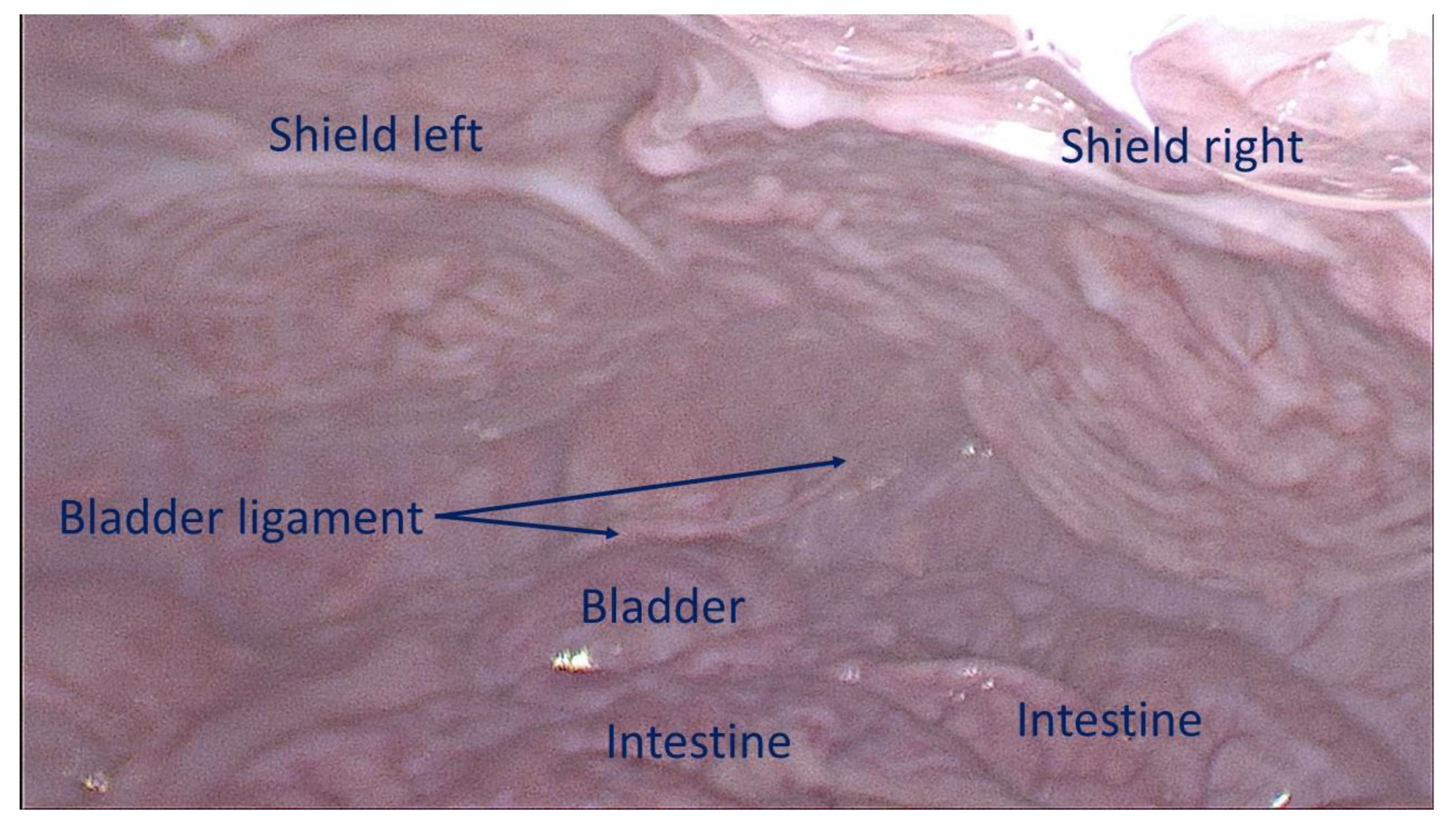
Figure 7.
Intraabdominal view during laparoscopic control 6 months post-surgery: both shields placed over the defects are clearly covered by healthy peritoneum. No adhesion bridles to visceral organs are present. After the laparoscopic control the animal has been euthanized, the S&S device was then removed and sent to histological study.
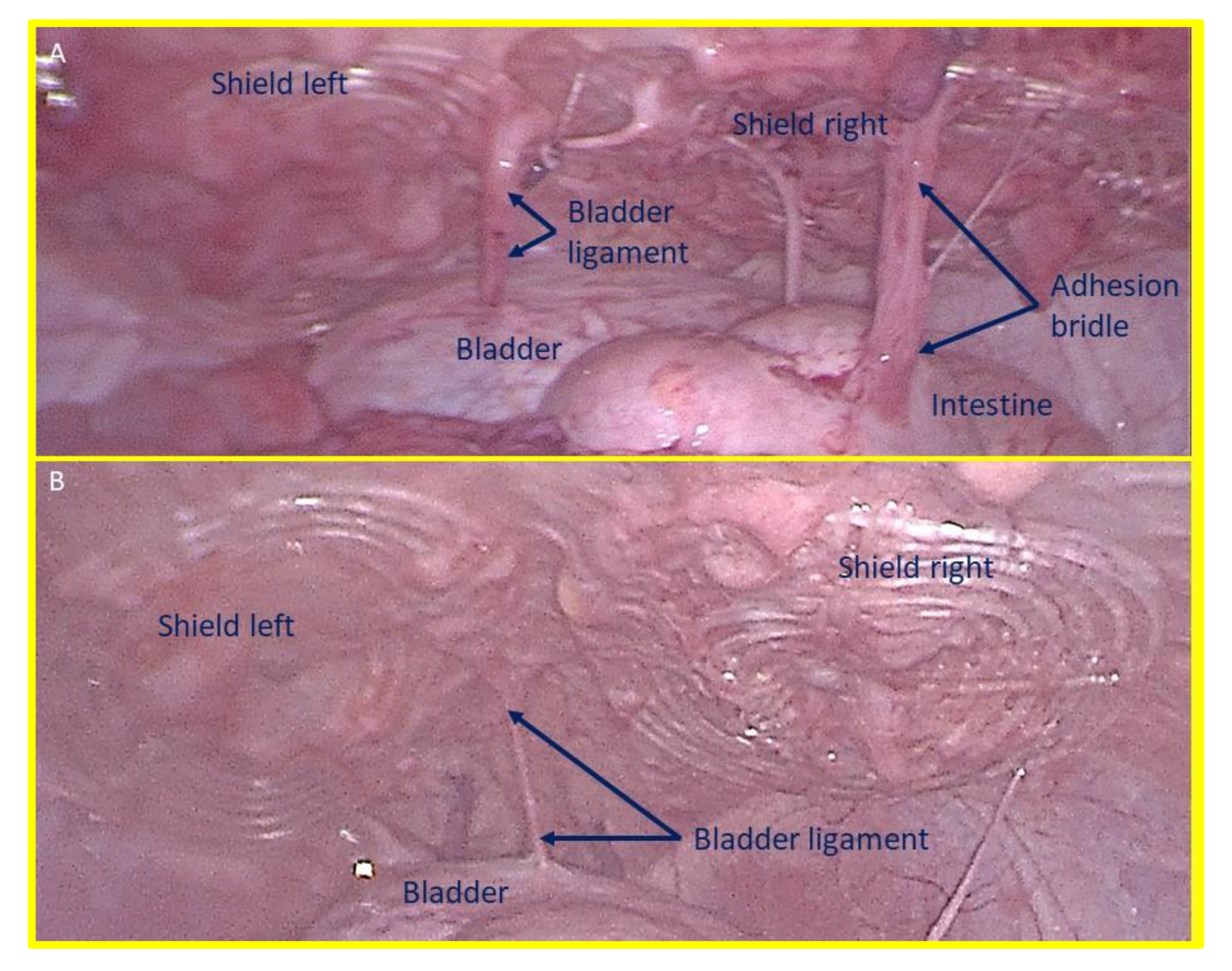
Figure 8.
– A: laparoscopic view of the shields positioned in the lower abdomen at the control 1 month postop. Exuberant mesothelial growth over both shields. The right sided shield shows an adhesion bridle to the intestine. – B: Laparoscopic control three months post-surgery. Both shields are increasingly covered by mesothelial tissue.
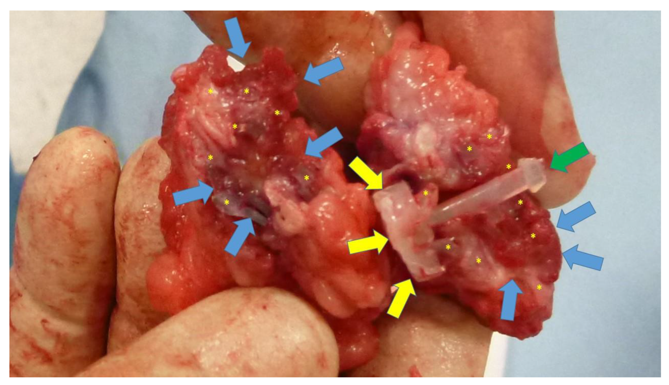
Figure 9.
Scaffold of the S&S device explanted 6 months post-surgery and cut in half: the 3D chamber of the scaffold formed by the bent rays of the device (*) is evidently filled by newly ingrown fleshy tissue resembling viable muscular structure (blue arrows). Notable features include the distal portion of the mast with the conic stop (green arrow) and the button-like enlargement on the opposite side (yellow arrows).
Figure 10.
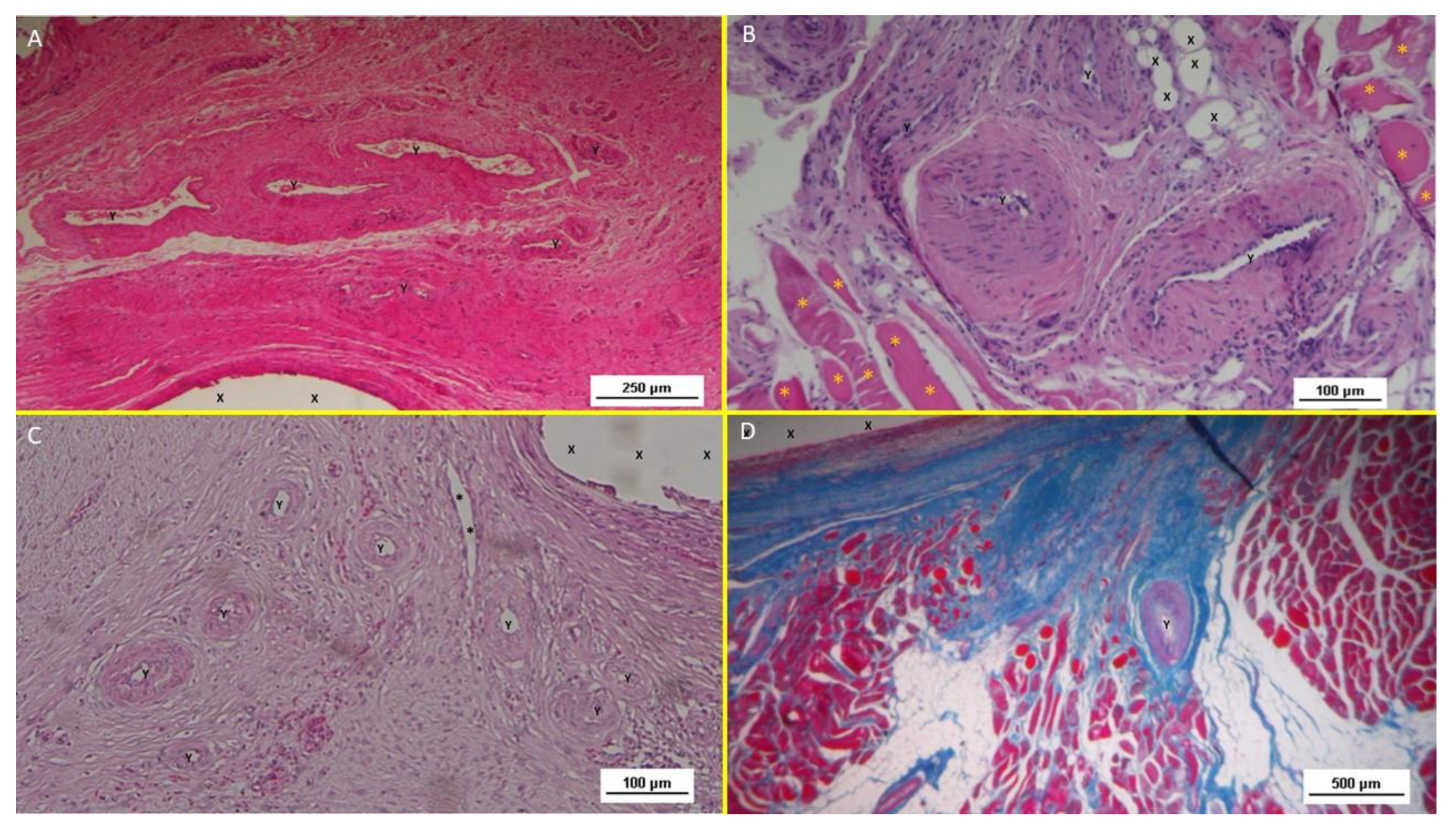
A: biopsy specimen excised 1 month post implantation: mild inflammatory infiltrate surrounding the structure of the S&S device (X). Of note the large vascular elements close to the S&S device (Y). HE 50X. - B: biopsy specimen excised 3 months post implantation: absent inflammatory infiltrate surrounding the structure of the S&S device (X) and close to large convoluted arterial elements (Y) surrounded by a discrete amount of muscular fibers (*) HE 100X. - C: biopsy from S&S scaffold removed 6 months postop: several mature arterial structures (Y) and one vein (*) in a context of lax and woven connective, close to the fabric of the S&S device. HE 100X. -10 D: biopsy sample excised 8 months post implantation. Mature muscle bundles (colored in red) developed close to the structure of the S&S device (X) surrounded by adipocytes (colored in white). A midsized arteriolar element is visible between the newly ingrown musculature (Y) AM 25X.
Figure 10.
A: biopsy specimen excised 1 month post implantation: mild inflammatory infiltrate surrounding the structure of the S&S device (X). Of note the large vascular elements close to the S&S device (Y). HE 50X. - B: biopsy specimen excised 3 months post implantation: absent inflammatory infiltrate surrounding the structure of the S&S device (X) and close to large convoluted arterial elements (Y) surrounded by a discrete amount of muscular fibers (*) HE 100X. - C: biopsy from S&S scaffold removed 6 months postop: several mature arterial structures (Y) and one vein (*) in a context of lax and woven connective, close to the fabric of the S&S device. HE 100X. -10 D: biopsy sample excised 8 months post implantation. Mature muscle bundles (colored in red) developed close to the structure of the S&S device (X) surrounded by adipocytes (colored in white). A midsized arteriolar element is visible between the newly ingrown musculature (Y) AM 25X.
Figure 11.
- A: Biopsy specimen removed eight months post implantation: well structured muscle bundles arranged in a fusiform element (colored in red) in a surround of healthy and compact connective (colored in blue) close to the fabric of the S&S device (X). AM 25X - B: Biopsy sample removed from the 3D scaffold of the S&S device 3 months after implantation. The figure shows several nervous elements (colored in brown) close to the TPE fiber of the scaffold (X). NSE 25X – The microphotograph left below highlights in a nervous element higher magnification. NSE 200X - C: Biopsy sample excised 6 months after implantation of the S&S device. The low magnification image shows several nervous elements (blue arrows) close to the TPE fiber of the scaffold (X). NSE 25x – The microphotograph right above details one nerve showing fully mature axon components and a healthy myelin sheath. NSE 200X - D: Biopsy specimen excised 4 weeks after implantation showing several vascular structures (white elongated oval spots) in the stage of endothelial development close to the structure of the S&S device (X). VEFG 100X.
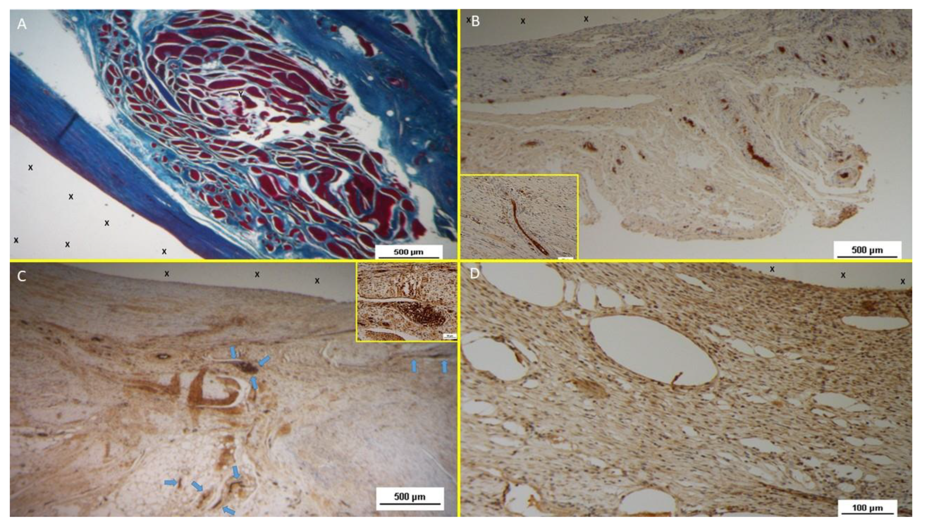
Figure 12.
A: Tissue sample removed from the 3D scaffold of the S&D device six months implantation. Numerous clusters of intense neo-angiogenesis (colored in brown) with well-developed vascular structures are clearly evident close to the device fabric (X). CD31 50X - B: Tissue sample excised from the 3D scaffold of the S&S device 8 months post-surgery. Numerous venous elements showing well-constituted muscular layer are highlighted close to the scaffold fabric (X). SMA 100X - The high magnification microphotograph in the right upper corner depicts two arterial structures with a well-represented muscular layer (colored in brown). SMA 200X - C: Biopsy sample excised from the scaffold of the S&S device 6 months post implantation. The image shows plenty of muscular elements (colored in brown) grouped in bundles close to the TPE structure of the device. NGF 25X - D: Biopsy specimen excised from the 3D scaffold of the S&S device 6 months post-implantation. The image shows a mature elongated nervous structure (colored in brown) developed within the TPE scaffold. NGFRp75 100X.
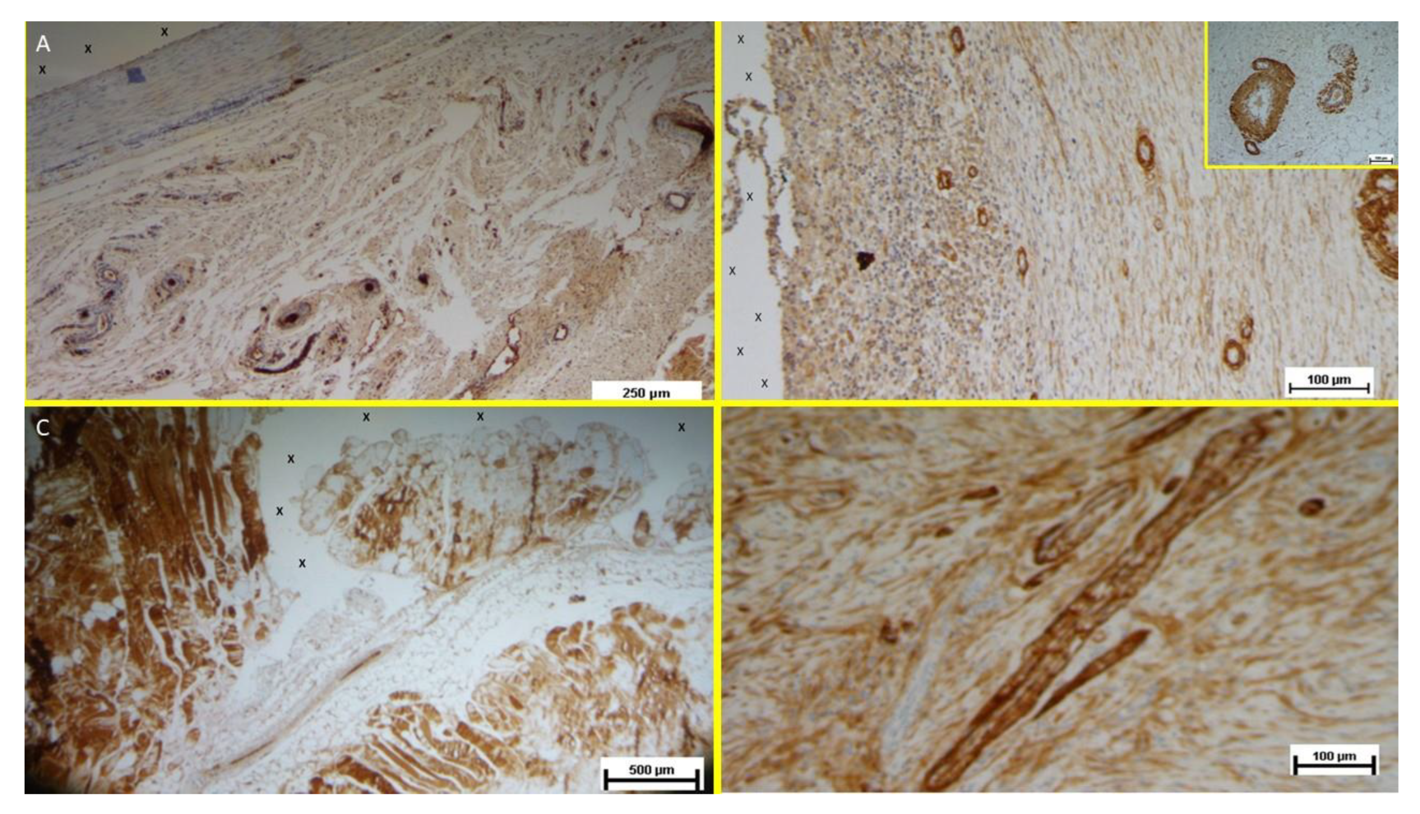
Table 1.
technical properties of the TPE material used for the injection molding of the Stenting & Shielding Hernia System.
Table 1.
technical properties of the TPE material used for the injection molding of the Stenting & Shielding Hernia System.
| TPE technical properties |
Value |
Unit |
Test Standard |
| ISO Data |
|---|
| Tensile Strength |
16 |
MPa |
ISO 37 |
| Strain at break |
650 |
% |
ISO 37 |
| Compression set at 70 °C, 24h |
54 |
% |
ISO 815 |
| Compression set at 100 °C, 24h |
69 |
% |
ISO 815 |
| Tear strength |
46 |
kN/m |
ISO 34-1 |
| Shore A hardness |
89 |
- |
ISO 7619-1 |
| Density |
890 |
kg/m³ |
ISO 1183 |
|
Disclaimer/Publisher’s Note: The statements, opinions and data contained in all publications are solely those of the individual author(s) and contributor(s) and not of MDPI and/or the editor(s). MDPI and/or the editor(s) disclaim responsibility for any injury to people or property resulting from any ideas, methods, instructions or products referred to in the content. |
© 2025 by the authors. Licensee MDPI, Basel, Switzerland. This article is an open access article distributed under the terms and conditions of the Creative Commons Attribution (CC BY) license (http://creativecommons.org/licenses/by/4.0/).