Introduction
Abdominal wall hernia repair typically relies on the use of biocompatible prostheses. These meshes, predominantly made of polypropylene, aim to strengthen the groin by promoting the development of fibrotic tissue. [
1,
2] Despite ongoing advancements in surgical management and materials, numerous adverse events have been reported, impacting both intraoperative and postoperative outcomes, reducing patient quality of life, and significantly increasing healthcare costs. Among these unsatisfying results, the uncontrolled and suboptimal biological response of conventional hernia meshes—exacerbated by the challenges of prosthetic fixation in the highly motile environment of the abdominal wall —assumes a significant character. This inadequate outcome is often linked to adverse events like discomfort and/or chronic pain. [
3,
4,
5,
6]
Moreover, the widely accepted wording "reinforcement" of the deteriorated groin may be deceptive. The development of stiff fibrotic scar induced by static hernia implants does not genuinely reinforce the herniated abdominal wall but merely constitutes a foreign body response. As per the connection amid this treatment approach and the underlying pathology of hernia protrusion, it becomes clear that conventional flat meshes fail to address the degenerative origin of hernia disease. [
7,
8,
9] Instead of "reinforcing" the groin with poorly vascularized and rigid fibrotic tissue—leaving a patent defect—the goal should be to permanently obliterate the defect and induce the development of new tissue, thereby restoring a proficient abdominal wall.
In response to the mobile nature of the abdominal wall and the degenerative source of visceral protrusion disease, recently a novel concept of treatment has emerged. This concept centers on the Stenting & Shielding (S&S) Hernia System, a newly conceived device produced through injection-molded polypropylene-based Thermo-Polymer Elastomer (TPE). Unlike conventional flat meshes, this 3D-structured device is designed to be positioned without fixation, ensuring effective obliteration of the hernial defect. Its inherent compliance with abdominal wall movements enables a physiological interaction, harmonizing with the natural dynamics of the abdominal musculature. This dynamic compliance fosters a biological response that is distinctly different from the rigid, fibrotic reaction typically induced by static hernia prostheses.
Experimental studies carried out on large animal models have highlighted the regenerative properties of the S&S hernia device, which functions as a regenerative scaffold. Alongside the ingrowth of viable connective, the S&S device supports the ingrowth of new muscular elements as well as newly developed nervous structures. Crucially, to sustain the function of these specialized tissues, the concurrent development of a competent network of mature arteries and veins is essential. This experimental investigation aims to document the development at defined stages of newly formed vascular structures within the 3D scaffold of the Stenting & Shielding Hernia System implanted in experimental pigs.
Material and Methods
The experimental study was carried out in strict accordance with the Protocol for Animal Care and Experimental Surgery, as required by the Ministry of Health of Italy. Approval for the protocol was granted under Decree No. 379/2021-PR, dated June 1st, 2021.
Between February 2022 and November 2024, ten female pigs with bilaterally created muscular defects in the lower abdomen were selected for the study. Each pig received laparoscopic placement of two Stenting & Shielding (S&S) Hernia Devices. The S&S device, designed to allow atraumatic and dissection-free management of several abdominal wall hernias types — in particular inguinal, but also incisional, femoral, Spigelian, and obturator hernias—was employed for this purpose.
Aged between 4 and 6 months, the animals had a body weight ranging from 40 to 60 kg. After premedication with tiletamine (6.3 mg/kg), xylazine (2.3 mg/kg) and zolazepam as well as induction with propofol (0.5 mg/kg), all laparoscopic interventions were performed under general anesthesia Maintenance was assured with isoflurane combined with pancuronium (0.07 mg/kg). Oxytetracycline (20 mg/kg/day) was administered as postoperative antibiotic prophylaxis for three days.
Stenting & Shielding Hernia System: Structure
The S&S Hernia System used in this study is fabricated from medical-grade, polypropylene-based Thermo-Polymer Elastomer (TPE). The technical properties of the material are presented in
Table 1.
The device comprises two main components: an eight-rayed structure contouring a central mast, and a 3D oval shield dimensioned 10x8 cm with a ring positioned at its center. The mast is equipped with a button-like structure at its distal end, along with two conic enlargements (stops) in proximity of the button. Initially, the device is configured as a cylindrical unit, with the oval shield threaded onto the mast via its central ring (
Figure 1A & B). This design allows the device to be delivered intraabdominally via a 12 mm channel. Once positioned inside the hernia defect, a metallic tube is used to advance the oval shield forward into the muscular defect. As the shield is moved beyond one or both conic stops on the mast, the cylindrical rayed structure expands inside the defect, creating an oval 3D scaffold that permanently occupies the hernia opening. This configuration locks the shield, preventing backward slippage, and blocks the scaffold within the defect, with the shield overlapping the muscular opening and making contact with the abdominal viscera (
Figure 1C). The final diameter of the 3D scaffold used in this study is approximately 4.5 cm.
Follow-up Protocol
Of the 10 pigs, two were sacrificed between 4 and 6 weeks postoperatively (short-term period), three between 3 and 4 months (mid-term) and five between 5 and 8 months (long-term). Scheduled ultrasound (
Figure 1D) and laparoscopic evaluations were conducted at planned postoperative stages to confirm the proper positioning of the 3D scaffold and to visually verify if adhesions between abdominal viscera and shield were present.
At the time of euthanasia, all S&S devices were removed through an incision in the lower midline. The S&S devices were then carefully cleared of the host’s native tissue and cut in half for macroscopic evaluation of the tissue ingrown within the 3D scaffold (
Figure 2).
The explanted devices were subsequently sent for a comprehensive histological evaluation regarding the development of the vascular elements.
Histology and immunohistochemistry methods
Tissue specimens excised from the core of the S&S scaffold were fixed for a minimum of 12 hours in 10% phosphate-buffered formalin before being embedded in paraffin. Sections of 4 μm thickness were cut and stored at room temperature until use. Routine histology (Hematoxylin–eosin staining, H&E) was performed to assess the histomorphological characteristics of the tissues developed within the 3D scaffold of the S&S device at the planned postoperative stages. Immunohistochemistry was carried out using CD31 (clone JC70A, 1:50 dilution, Dako-Agilent, Carpinteria, CA, USA),staining to assess the vascular density in the specimens.
Serial sections (4 μm thick) on glass slides were washed in xylene and hydrated in different (decreasing) concentrations of alcohol. After dewaxing, the slides were heated in a solution of sodium citrate (pH 6.0) at 96° C for 20 min for antigen retrieval. Endogenous peroxidase activity was blocked with 3% hydrogen peroxide for 30 min. Slides were treated with 1% bovine serum albumin (BSA) for 30 min and incubated for 1 hour at room temperature in the presence of 0.1% BSA with an antibody against CD31. After two rinses with phosphate-buffered saline (PBS) tissue sections were treated for 30 min with universal polymer labeled with Horseradish Peroxidase (MACH-1, Bio Optica, Milan, Italy), followed by the chromogen 3-3′ diamminobenzidine tetrahydrochloride (DAB) for 3 min and counterstained with Mayer's haematoxylin. The specific primary antibody was replaced by PBS in tissue sections used as negative controls. The DAB-reaction developed a brown precipitate, when positive.
Histologic and immunohistochemical assessment
Tissue specimens were analysed at high magnification by light microscopy to examine the tissue interface of the S&S device. A semi-quantitative histological analysis was conducted, focusing on the quality and quantity of the vascular structures identified in the histological slides. The morphological aspect of the vascular elements were assessed using digital images of the stained sections. Images were captured using a bright-light microscope, digital camera, and image capture software (Leica DMLB microscope, Nikon DS-Fi-1 digital camera, NIS Basic Research Nikon software).
Statistical Analysis
The density of the vascular network was identified with CD 31 in 20 samples of the S&S device removed at different stages post-surgery. Four specimens 3-5 weeks (short term) post-implantation, six samples 3-4 months PS (mid-term) and ten samples 6-8 months PS (long term) were analyzed. A one-way ANOVA between 20 samples was carried out to compare the density of the vascular network in the S&S scaffold at the different stages post-implantation (ST = short term, MT = mid-term and LT = long term). In addition, to assess significance of differences between stages, the Tukey–Kramer multiple comparison test was used. A p value <0.05 was considered significant. GraphPad Software (Inc., San Diego, CA, USA) was used for the analyses.
Results
Two pathologists evaluated the tissue samples and the related histological sections in blinded manner regarding the postoperative period. Tissue samples taken from the scaffold of the S&S device during the short-term period (3-5 weeks post-implantation) revealed an abundant presence of early-stage vascular clusters near the scaffold material, with minimal inflammatory response observed (
Figure 3,
Figure 4,
Figure 5 &
Figure 6).
In the mid-term period (3-4 months post-implantation), H&E staining showed a significant presence of vascular structures within the S&S device. Notably, in this postoperative period no signs of inflammatory response against the fabric of the S&S device could be evidenced. The arterial structures displayed advanced development, with well-defined endothelial and muscular layers, while the adventitia was properly enveloping the vessels. Similarly, the veins exhibited noticeable structural maturation compared to the earlier period (
Figure 7,
Figure 8 &
Figure 9).
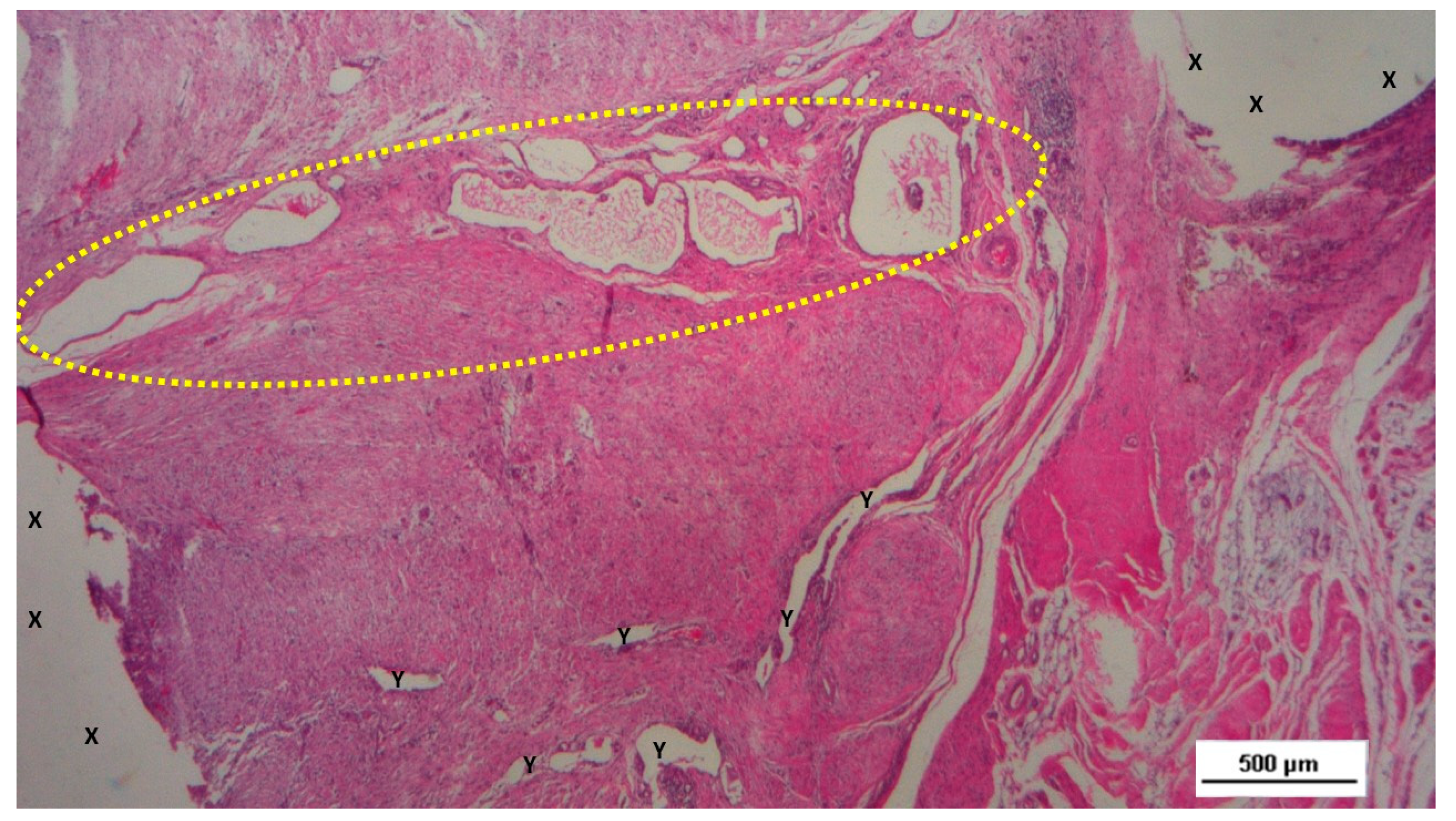
Figure 7.
Biopsy specimen excised three months post-surgery. Microphotograph reveals a large convoluted arterial structure (yellow circle) and several clusters of veins (Y) in advanced stages of development, embedded in well-perfused connective tissue near the S&S scaffold fabric (X), which is free from inflammation. The lower right corner highlights bundles of mature muscle elements (red spots). HE 25X.
Figure 8.
Biopsy taken four months post-surgery from the 3D scaffold of the S&S Hernia System. Numerous clusters of vascular structures are in advanced stages of development (yellow circle), surrounded by well-hydrated, slack connective tissue containing several muscle bundles (red-stained dotted and striped structures) near the S&S fabric (X), with no signs of inflammation. HE 25X.
Figure 9.
Biopsy taken four months post-surgery from the 3D scaffold of the S&S Hernia System. Numerous clusters of vascular structures are in advanced stages of development (yellow circle), surrounded by well-hydrated, slack connective tissue containing several muscle bundles (red-stained dotted and striped structures) near the S&S fabric (X), with no signs of inflammation. HE 25X.
Figure 10.
Biopsy taken four months post-implantation from the 3D scaffold of the S&S Hernia System. Numerous vascular elements in advanced stage of development (stained in brown), close to the S&S fabric (X). CD31 50X.
Figure 10.
Biopsy taken four months post-implantation from the 3D scaffold of the S&S Hernia System. Numerous vascular elements in advanced stage of development (stained in brown), close to the S&S fabric (X). CD31 50X.
6-8 months post-implantation (long-term stage), there was a complete absence of inflammation, and the newly formed arteries and veins demonstrated full structural maturation across all components (
Figure 11,
Figure 12,
Figure 13,
Figure 14 &
Figure 15).
Statistical analysis
The vascular density of 20 biopsies excised from the scaffold of the S&S Hernia System at various postoperative periods was compared using one-way ANOVA followed by a post hoc Tukey test. The results revealed statistically dissimilarities worth of note between the examined periods (
Table 2) revealing that the concentration of the vascular elements in the scaffold of the S&S Hernia System increases over time up to long term stage. Overall, the findings suggest that vascular density in the long term is considerably higher compared to the short term.
Discussion
This study aimed to evaluate the integration of new vascular structures developed within the scaffold of the Stenting & Shielding (S&S) Hernia System positioned into a surgically created defect in the lower abdominal wall of 10 pigs. The defects created in the muscular structure of the abdominal wall were designed to replicate the key characteristics of human hernial openings. A hernia, by definition, is essentially a breach in the muscular barrier that separates the visceral compartment from the external environment. In this study, the surgically induced defects served as a controlled model to simulate this anatomical and functional disruption, enabling an evaluation of how the S&S device interacts with the abdominal wall and restores its integrity. Although the porcine abdominal wall differs slightly from the human counterpart in terms of thickness, it shares comparable structural composition, biomechanical properties and physiological behaviour, making it a well-established model for preclinical hernia research.
The 20 S&S devices implanted in 10 pigs were followed up, removed and histologically/immunohistochemically examined over defined postoperative periods: short-, mid- and long-term. The rationale for selecting these specific time frames is rooted in established research, which indicates that by 6-8 months post-implantation, tissue integration with hernia implants generally reaches completion and stabilizes [
10,
11,
12].
The importance of angiogenesis in flat and dynamically passive meshes for hernia repair has been well-documented. These conventional, flat implants prompt the early onset of vascular proliferation soon after implantation. Initially, this new vascular network supports the integration of the prosthesis through the development of fibrotic elements [
13,
14,
15,
16,
17,
18,
19,
20]. However, as the process continues, these meshes become incorporated in a rigid, fibrotic layer, causing the shrinkage of the mesh. [
21,
22,
23,
24,
25,
26,
27,
28,
29,
30] During this phase, the vascular network is reduced and primarily functions to sustain the chronic inflammatory response—characterized by plasma cells, lymphocytes and macrophages —that is typical of these prostheses. [
31,
32,
33] The resulting tissue is often of poor quality, forming dense, stiff scar tissue that can lead to complications such as adhesion formation and nerve entrapment, especially in the inguinal region, potentially causing discomfort and chronic pain.
Understanding the biological processes involved in neo-vessel formation within newly developed tissue is crucial for appreciating the differences observed with the S&S device. Neo-angiogenesis is crucial for the metabolic support to developing tissues. [
34,
35,
36,
37,
38,
39,
40,
41] However, in conventional hernia meshes, the vascular network often fails to fully mature; instead, it primarily supports the maintenance of chronic inflammation rather than nourishing healthy tissue growth. [
42] This is not the case with the S&S Hernia System.
In contrast, the structural nature of the 3D scaffold—combined with its unique surface design—creates a biomechanically compliant environment. This compliance facilitates tissue integration by mimicking the physiological movements of the abdominal wall. Unlike flat meshes, which rely solely on passive reinforcement, the S&S device’s dynamic properties actively promote cellular migration and proliferation, contributing to the development of organized vascular, muscular, and nervous structures. Moreover, the use of a medical-grade polypropylene-based thermoplastic elastomer (TPE) ensures long-term structural stability without degradation under physiological conditions. This material’s durability minimizes the risk of adverse inflammatory reactions associated with degraded by-products, as seen in resorbable meshes. [
43,
44]
The S&S Hernia System elicits a “probiotic” biological response—an active, regenerative process that not only fills the hernia defect but also restores the integrity of the abdominal wall barrier. This process directly addresses the degenerative mechanisms underlying hernia disease.
The constant development of healthy tissue, supported by continuous and effective ingrowth of new vascular structures, is essential for the growth of complex tissue structures, such as muscle and nerve fibers. The scaffold’s dynamic interaction with abdominal wall movements further stimulates endothelial activity, facilitating nutrient exchange and cellular signalling pathways critical for angiogenesis. The findings of this study suggest that angiogenesis within the 3D scaffold of the S&S device is not only persistent but also evolves in tandem with the development of these particularly specialized tissue components.
In the short term, the histological analysis revealed the presence of immature vascular structures, indicative of early-stage angiogenesis. By the mid-term, a more extensive and organized vascular network had formed, with ongoing vascular development occurring inside the structure of the S&S device. In the long-term phase, the study observed the continued maturation of these vascular elements, which paralleled the development of other tissue components, particularly muscle fibers and nerves. By this stage, the muscular layer of the arterial and venous walls had fully matured, demonstrating the establishment of a competent vascular network capable of sustaining the newly formed, sophisticated tissues within the scaffold. In this final phase of vascular development, all vessel elements—arteries, veins, and capillaries—exhibited the structural characteristics of fully matured vessels. This well-established vascular network ensures adequate blood supply to the newly formed tissues, particularly muscle and nerve tissues, within the S&S device. All these evidences have been confirmed in detail by the statistical assessment.
Our experience with the polypropylene-based thermoplastic elastomer (TPE) device used in this study suggests that its unique dynamic properties play a pivotal role in promoting persistent angiogenesis. The transition from a reactive, transient neoangiogenesis to sustained vascular development and maturation appears to be driven by the material's intrinsic elasticity and its responsiveness to the cyclical mechanical forces of the surrounding muscular environment. Unlike static materials, the TPE scaffold's dynamic compliance to the physiological loading of the abdominal wall creates a biomechanically active interface that mimics natural tissue behavior. This continuous, adaptive interaction seems to stimulate endothelial cell activity, facilitating nutrient exchange, cellular signaling, and growth factor release, all of which are critical for vascular proliferation and maturation. Furthermore, the material's steady responsiveness prevents chronic inflammation and the consequent development of rigid fibrotic scar tissue, which in conventional static implants is often associated with impaired angiogenesis. [
45,
46] Instead, the TPE scaffold fosters an environment conducive to the ingrowth of functional, organized vascular structures, thereby underpinning its probiotic features and promoting long-term tissue regeneration.
Overall, the findings of this study align with previous research that highlights the regenerative capabilities of dynamic scaffolds in hernia repair. [
47,
48,
49,
50] The S&S Hernia System, with its ability to support ongoing angiogenesis and tissue maturation, demonstrates significant potential as a dynamic regenerative scaffold for the effective treatment of hernia defects.
Conclusion
The histological findings from this study suggest that the biological response to biocompatible prostheses used for hernia repair is strongly influenced by their structural design. Traditional static and passive flat meshes consistently trigger a foreign body response, causing the development of rigid, avascular fibrotic tissue. In contrast, when comparable biocompatible material is configured in a dynamically compliant scaffold like the Stenting & Shielding (S&S) Hernia System, the biological response is markedly different. The S&S device, designed to move in harmony with the abdominal wall, fosters a more favorable environment for tissue regeneration. This dynamic interaction appears to promote the development of newly formed myocytes and nerve structures supported by a well-developed network of blood vessels. Essentially, this device functions as a regenerative scaffold, aligning with the therapeutic goals of addressing the tissue degeneration underlying hernia formation. However, this study has a significant limitation embodied by lacking explanation for the mechanisms driving the observed neoangiogenesis. Preliminary observations indicate that tissue growth factors could have a role in enhancing the biological response and sustaining the development of new vascular structures. Further research is needed to elucidate these mechanisms. The promising results from this animal model lay a strong basis for future clinical investigations. These studies will be crucial in determining whether the positive biological responses observed here can be replicated in humans. If validated, the S&S Hernia System could represent a significant advancement in hernia repair, potentially simplifying surgical procedures and improving patient outcomes.
Supplementary Materials
The following supporting information can be downloaded at the website of this paper posted on Preprints.org.
Authors Contributions: AG Conceptualization AA Formal Analysis RV Investigation PR Methodology DBG Software CG Validation CL Resources CR Data Curation RG Formal Analysis NC Original Draft Preparation RW Review & editing RG Supervision.
Funding
This research received no external funding.
Data Availability Statement
All data supporting the reported results are available upon request from the corresponding author.
Conflicts of Interest
The corresponding author is the developer of the device described in the report. The other authors declare no conflict of interest.
References
- Kingsnorth, A.; LeBlanc, K. Hernias: inguinal and incisional. Lancet 2003, 362, 1561–71. [Google Scholar] [CrossRef] [PubMed]
- Debord, J.R. The historical development of prosthetics in hernia surgery. Surg Clin North Am 1998, 78, 973–10063. [Google Scholar] [CrossRef] [PubMed]
- Amid, P.K. Causes, prevention, and surgical treatment of postherniorrhaphy neuropathic inguinodynia: Triple neurectomy with proximal end implantation. Hernia 2004, 8, 343–349. [Google Scholar] [CrossRef] [PubMed]
- O’Dwyer, P.J.; Kingsnorth, A.N.; Mohillo, R.G.; Small, P.K.; Lammers, B.; Horeysee, G. Randomized clinical trial assessing impact of a lightweight or heavyweight on chronic pain after inguinal hernia repair. Br J Surg 2005, 92, 166–70. [Google Scholar] [CrossRef]
- Rutkow, I.M.; Robbins, A.W. Mesh plug hernia repair: a follow-up report. Surgery 1995, 117, 597–598. [Google Scholar] [CrossRef]
- Aasvang, E.; Kehlet, H. Surgical management of chronic pain after inguinal hernia repair. Br J Surg 2005, 92, 795–801. [Google Scholar] [CrossRef]
- Amato, G.; Ober, E.; Romano, G.; Salamone, G.; Agrusa, A.; Gulotta, G.; Bussani, R. Nerve degeneration in inguinal hernia specimens. Hernia 2011, 15, 53–58. [Google Scholar] [CrossRef]
- Amato, G.; Agrusa, A.; Romano, G.; Salamone, G.; Gulotta, G.; Silvestri, F.; Bussani, R. Muscle degeneration in inguinal hernia specimens. Hernia. 2012, 16(3), 327–31. [Google Scholar] [CrossRef]
- Amato, G.; Calò, P.; Rodolico, V.; Puleio, R.; Agrusa, A.; Gulotta, L.; Gordini, L.; Romano, G. The Septum Inguinalis: A Clue to Hernia Genesis? J Invest Surg. 2018, 1–9. [Google Scholar] [CrossRef]
- Kilkenny, C.; Browne, W.J.; Cuthill, I.C.; Emerson, M.; Altman, D.G. Improving Bioscience Research Reporting: The ARRIVE Guidelines for Reporting Animal Research. PLoS Biol 2010, 8, e1000412. [Google Scholar] [CrossRef]
- Weidner, N. Current pathologic methods for measuring intratumoral microvessel density within breast carcinoma and other solid tumors. Breast Cancer Res Treat. 1995, 36, 169–80. [Google Scholar] [CrossRef] [PubMed]
- Amid, P.K.; Shulman, A.G.; Lichtenstein, I.L.; Hakakha, M. Biomaterials for abdominal wall hernia surgery and principles of their applications. Langenbecks Arch Chir 1994, 379, 168–71. [Google Scholar] [CrossRef] [PubMed]
- Klinge, U.; Klosterehalfen, B.; Muller, M.; Ottinger, A.P.; Schumpelick, V. Shrinking of polypropylene mesh in vivo: An experimental study in dogs. Eur J Surg 1998, 164, 96. [Google Scholar] [CrossRef] [PubMed]
- Klosterhalfen, B.; Klinge, U.; Schumpelick, V. Functional and morphological evaluation of different polypropylene-mesh modifications for abdominal wall repair. Biomaterials 1998, 19, 2235–2246. [Google Scholar] [CrossRef]
- EU Hernia Trialist Collaboration. Mesh compared with nonmesh methods on open groin hernia repair. Systematic review of randomized controlled trial. Br J Surg 2000, 87, 854–859. [Google Scholar] [CrossRef]
- Read, R.C. Recent advances in the repair of groin herniation. Curr Probl Surg 2003, 40, 13–79. [Google Scholar] [CrossRef]
- Amid, P.K. Lichtenstein tension-free hernioplasty: Its inception, evolution, and principles Hernia. 2004, 8, 1–7. [Google Scholar] [CrossRef]
- Amid, P.K. Shrinkage: fake or fact? In Meshes: benefits and risks; Schumpelick V, Nyhus LM, Ed.; Springer: Berlin, 2004. [Google Scholar]
- Klosterhalfen, B.; Junge, K.; Klinge, U. The lightweight and large porous mesh concept for hernia repair. Expert Rev Med Devices 2005, 2, 103–117. [Google Scholar] [CrossRef]
- Amid, P.K. Causes, prevention, and surgical treatment of postherniorrhaphy neuropathic inguinodynia: Triple neurectomy with proximal end implantation. Hernia 2004, 8, 343–349. [Google Scholar] [CrossRef]
- Bay-Nielsen, M.; Perkins, F.M.; Kehlet, H. Danish Hernia Database Pain and functional impairment 1 year after inguinal herniorrhaphy: a nationwide questionnaire study. Am J Surg 2001, 233, 1–7. [Google Scholar]
- Langbach, O.; Holmedal, S.H.; Grandal, O.I.; Røkke, O. Adhesions to mesh after ventral hernia mesh repair are detected by MRI but are not a cause of long term chronic abdominal pain. Gastroenterol Res Pract 2016, 2016, 2631598. [Google Scholar] [CrossRef] [PubMed]
- Bay-Nielsen, M.; Nilsson, E.; Nordin, P.; Kehlet, H.; Swedish Hernia Data Base the Danish Hernia Data Base. Chronic pain after open mesh and sutured repair of indirect inguinal hernia in young males. Br J Surg 2004, 91, 1372–1376. [Google Scholar]
- Kehlet, H.; Bay-Nielsen, M. Nationwide quality improvement of groin hernia repair from the Danish Hernia Database of 87,840 patients from 1998 to 2005. Hernia 2008, 12, 1–7. [Google Scholar] [CrossRef]
- Nienhuijs, S.; Staal, E.; Strobbe, L.; Rosman, C.; Groenewoud, H.; Bleichrodt, R. Chronic pain after mesh repair of inguinal hernia: a systematic review. Am J Surg 2007, 194, 394–400. [Google Scholar] [CrossRef] [PubMed]
- Loos, M.J.; Roumen, R.M.; Scheltinga, M.R. Classifying postherniorrhaphy pain syndromes following elective inguinal hernia repair. World J Surg 2007, 31, 1760–1765. [Google Scholar] [CrossRef] [PubMed]
- Aasvang, E.K.; Gmaehle, E.; Hansen, J.B.; et al. Predictive risk factors for persistent postherniotomy pain. Anesthesiology. 2010, 112, 957–969. [Google Scholar] [CrossRef] [PubMed]
- Burgmans, J.P.; Voorbrood, C.E.; Simmermacher, R.K.; et al. Long-term results of a randomized double-blinded prospective trial of a lightweight (Ultrapro) versus a heavyweight mesh (Prolene) in laparoscopic total extraperitoneal inguinal hernia repair (TULP-trial). Ann Surg. 2016, 263, 862–866. [Google Scholar] [CrossRef]
- Andresen KRosenberg, J. Management of chronic pain after hernia repair. J Pain Res. 2018, 11, 675–681. [Google Scholar] [CrossRef]
- Major, M.R.; Wong, V.W.; Nelson, E.R.; Longaker, M.T.; Gurtne, G.C. The foreign body response: at the interface of surgery and bioengineering. Plast Reconstr Surg 2015, 135, 1489–98. [Google Scholar] [CrossRef]
- Klopfleisch, R.; Jung, F. The pathology of the foreign body reaction against biomaterials. J Biomed Mater Res A 2017, 105, 927–940. [Google Scholar] [CrossRef]
- Geelhoed, W.J.; Moroni, L.; Joris, I.; Rotmans, J.I. Utilizing the Foreign Body Response to Grow Tissue Engineered Blood Vessels in Vivo. J. of Cardiovasc. Trans. Res. 2017, 10, 167–179. [Google Scholar] [CrossRef] [PubMed]
- Kumar, V.; Abbas, A.K.; Fausto, N. Blood Vessel. Robbins&Cotran Pathologic Basis of Disease, Philadelphia, Saunders. 2005; 513–515. [Google Scholar]
- Tozzi, P. The physiology of blood flow and artery wall. Springer editor. Sutureless Anastomoses, Darmstadt, Steinkopff. 2007; 12–24. [Google Scholar]
- Tannock, I.F.; Hayashi, S. The proliferation of capillary endothelial cells. Can Res. 1972, 32, 77–82. [Google Scholar]
- Nakatsu, M.N.; Hughes, C.C. An optimized three-dimensional in vitro model for the analysis of angiogenesis. Methods Enzymol. 2008, 443, 65–82. [Google Scholar] [PubMed]
- Potente, M.; Gerhardt, H.; Carmeliet, P. Basic and therapeutic aspects of angiogenesis. Cell. 2011, 146, 873–887. [Google Scholar] [CrossRef] [PubMed]
- Deindl, E.; Quax, P.H.A. Arteriogenesis and Therapeutic Angiogenesis-An Update. Int J Mol Sci. 2021, 22, 13244. [Google Scholar] [CrossRef]
- Eelen, G.; Treps, L.; Li, X.; Carmeliet, P. Basic and Therapeutic Aspects of Angiogenesis Updated. Circ Res. 2020, 127, 310–329. [Google Scholar] [CrossRef]
- Li, X.; Kumar, A.; Carmeliet, P. Metabolic Pathways Fueling the Endothelial Cell Drive. Annu Rev Physiol. 2019, 81, 483–503. [Google Scholar] [CrossRef]
- Anderson, J.M.; Rodriguez, A.; Chang, D.T. Foreign body reaction to biomaterials. Semin Immunol. 2008, 20, 86–100. [Google Scholar] [CrossRef]
- Pascual, G.; Sotomayor, S.; Rodriguez, M.; Perez-Koehler, B.; Bellon, J.M. Repair of Abdominal Wall Defects with Biodegradable Laminar Prostheses: Polymeric or Biological? PLoS ONE 2012, 7, e52628. [Google Scholar] [CrossRef]
- Shiroud Heidari, B.; Dodda, J.M.; El-Khordagui, L.K.; Focarete, M.L.; Maroti, P.; Toth, L.; Pacilio, S.; El-Habashy, S.E.; Boateng, J.; Catanzano, O.; Sahai, N.; Mou, L.; Zheng, M. Emerging materials and technologies for advancing bioresorbable surgical meshes. Acta Biomater. 2024, 184, 1–21. [Google Scholar] [CrossRef]
- Elango, S.; Perumalsamy, S.; Ramachandran, K.; Vadodaria, K. Mesh materials and hernia repair. Biomedicine (Taipei). 2017, 7, 16. [Google Scholar] [CrossRef]
- Clancy, C.; Jordan, P.; Ridgway, P.F. Polypropylene mesh and systemic side effects in inguinal hernia repair: current evidence. Ir J Med Sci. 2019, 188, 1349–1356. [Google Scholar] [CrossRef] [PubMed]
- Tanprasert, P.; Tepmalai, K.; Chakrabandhu, B.; Yodkeeree, S.; Piyamongkol, W.; Yamada, S.L. Collagen Deposition and Inflammatory Response Associated with Macroporous Mesh Shrinkage in Incisional Hernia Repair: A Rat Model. J Invest Surg. 2022, 35, 1635–1647. [Google Scholar] [CrossRef] [PubMed]
- Amato, G.; Puleio, R.; Romano, G.; Calò, P.G.; Di Buono, G.; Cicero, L.; Cassata, G.; Goetze, T.; Buscemi, S.; Agrusa, A.; et al. Physiologic Cyclical Load on Inguinal Hernia Scaffold ProFlor Turns Biological Response into Tissue Regeneration. Biology 2023, 12, 434. [Google Scholar] [CrossRef] [PubMed]
- Amato, G.; Romano, G.; Puleio, R.; Agrusa, A.; Goetze, T.; Gulotta, E.; Gordini, L.; Erdas, E.; Calò, P. Neomyogenesis in 3D Dynamic Responsive Prosthesis for Inguinal Hernia Repair. Artif Organs. 2018, 42, 1216–1223. [Google Scholar] [CrossRef]
- Amato, G.; Agrusa, A.; Puleio, R.; Calò, P.G.; Goetze, T.; Romano, G. Neo-nervegenesis in 3D dynamic responsive implant for inguinal hernia repair. Qualitative study. International Journal of Surgery 2012, 76, 114–119. [Google Scholar] [CrossRef] [PubMed]
- Amato, G.; Puleio, R.; Rodolico, V.; Agrusa, A.; Calò, P.G.; Di Buono, G.; Romano, G.; Goetze, T. Enhanced angiogenesis in the 3D dynamic responsive implant for inguinal hernia repair ProFlor®. Artif Organs. 2021, 00, 1–10. [Google Scholar] [CrossRef] [PubMed]
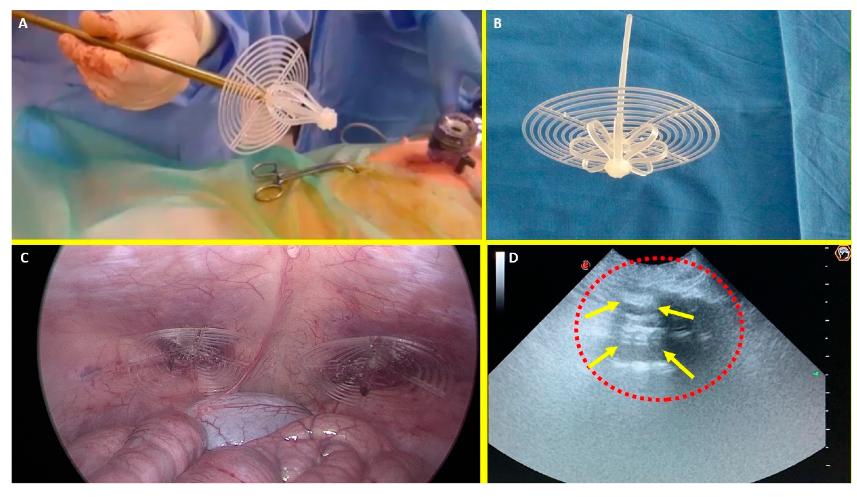
Figure 1.
A: The Stenting & Shielding (S&S) Hernia System in its pre-delivery configuration, prior to insertion into the abdominal cavity of the experimental pig. B: The S&S device fully deployed, illustrating its final structure. C: The two shields of the S&S Hernia System laparoscopically positioned in front of the intestine in the lower abdominal wall. D: Ultrasound scan six months post-implantation, showing the 3D scaffold (red circle) filled with newly ingrown tissue (yellow arrows).
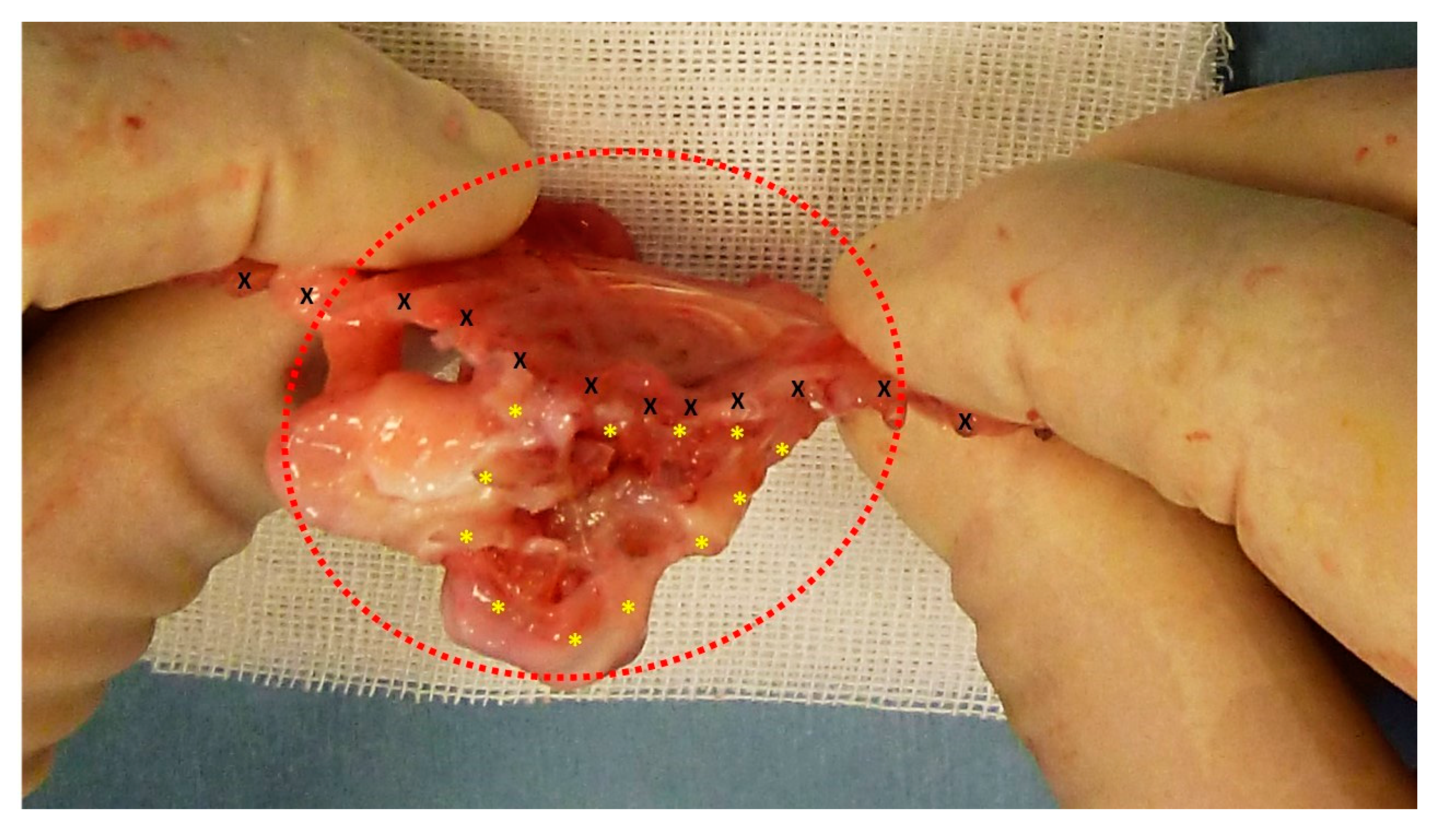
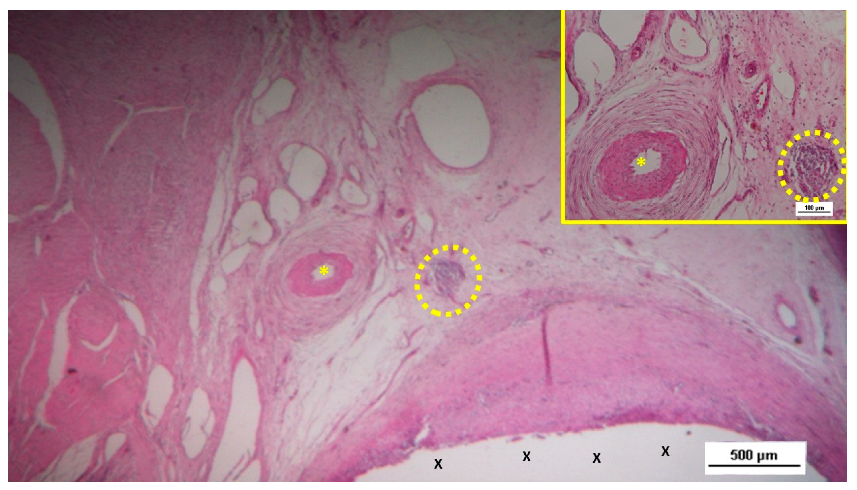
Figure 2.
The S&S Hernia System (red circle) excised three months post-implantation, bisected to reveal viable fleshy tissue (colored in red) that has grown into the 3D scaffold (*) of the device. The shield is indicated by X.
Figure 2.
The S&S Hernia System (red circle) excised three months post-implantation, bisected to reveal viable fleshy tissue (colored in red) that has grown into the 3D scaffold (*) of the device. The shield is indicated by X.
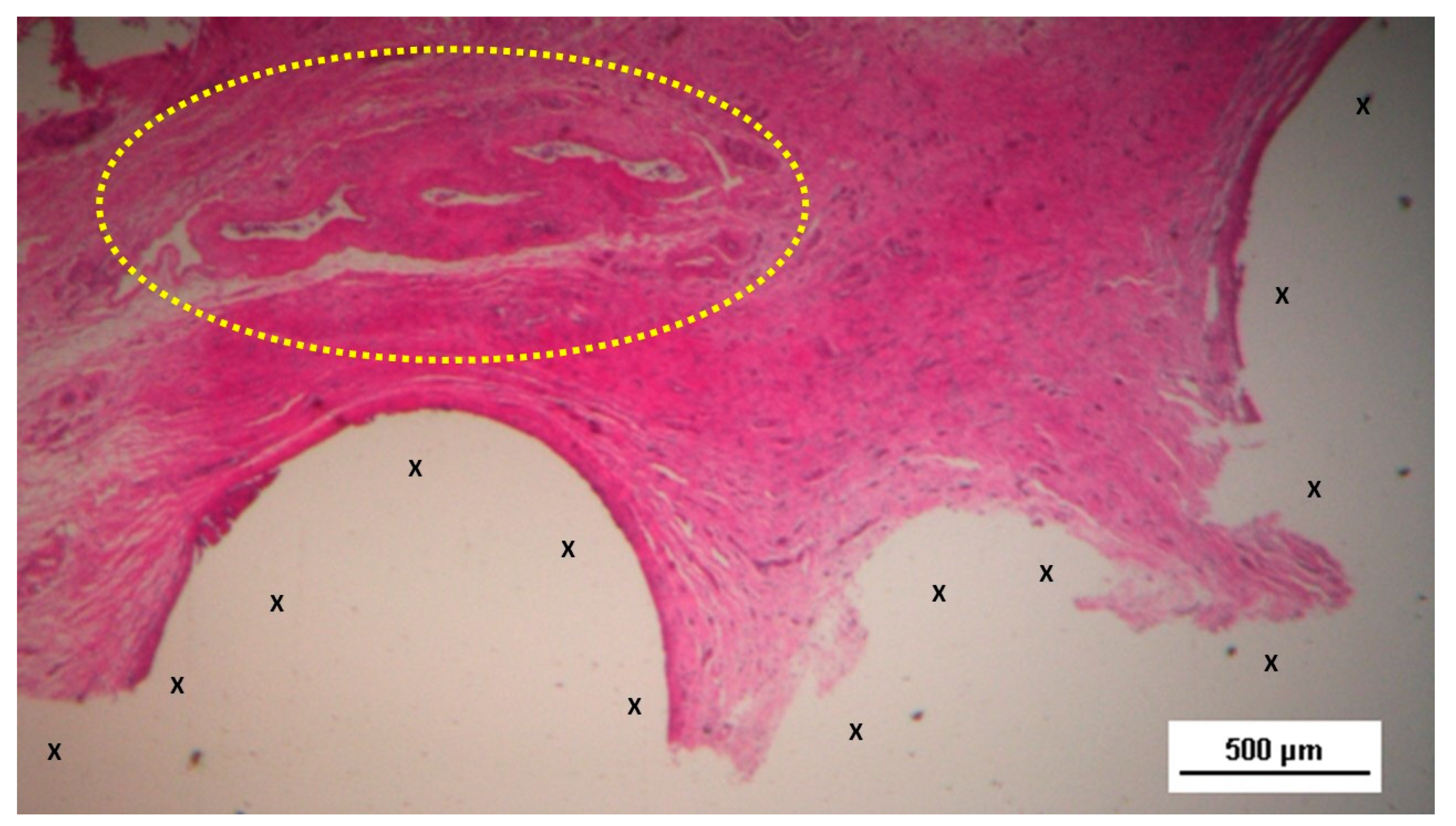
Figure 3.
Biopsy from the 3D scaffold of the S&S device, excised four weeks post-implantation (short-term). Microphotograph reveals numerous newly formed vascular structures in early development (*) adjacent to the S&S device fabric (X) with negligible inflammatory response in well-perfused connective tissue. The inset (right upper corner) provides a magnified view of these developing vascular elements. HE 50X (main image) and HE 100X (inset).
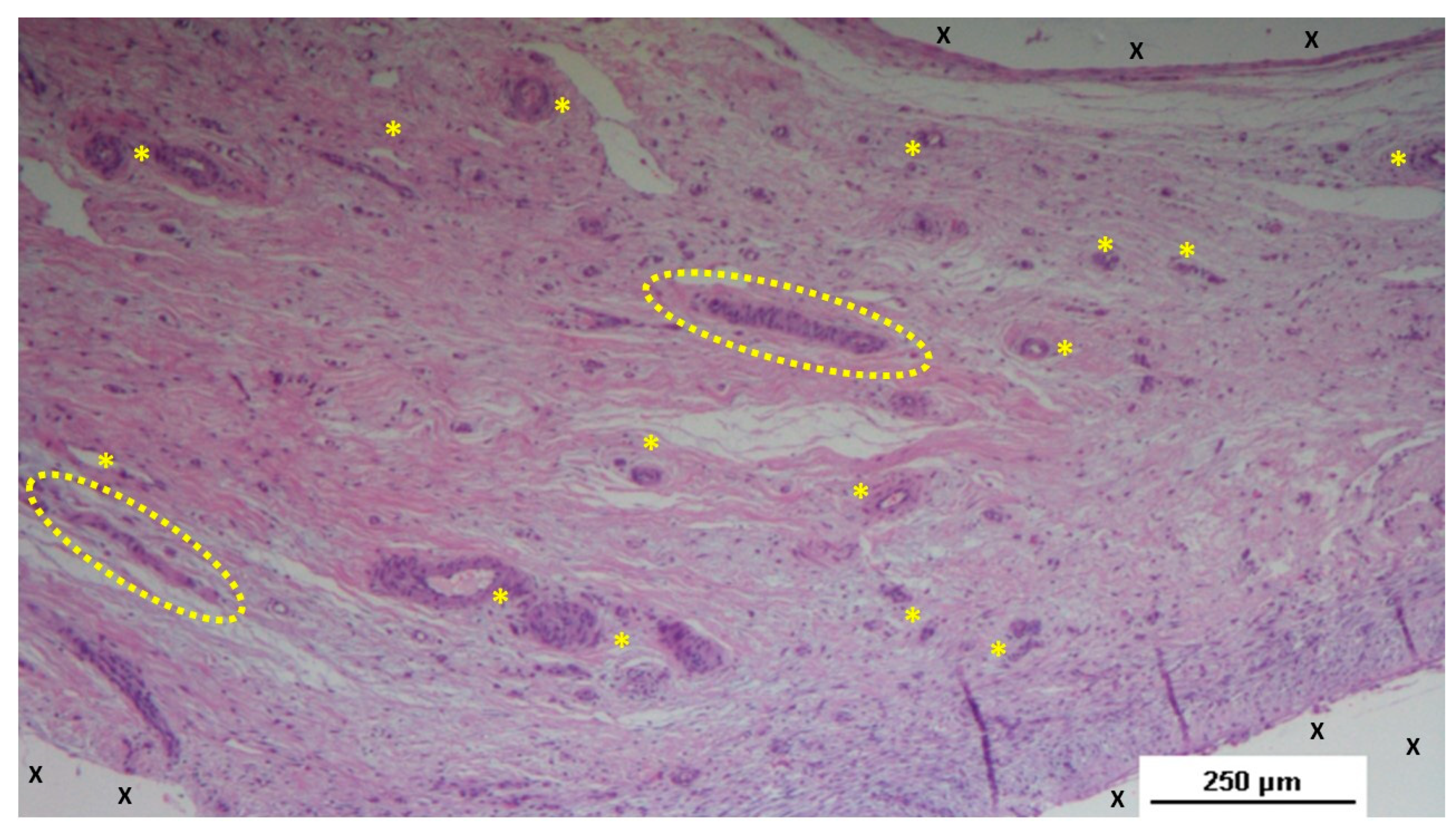
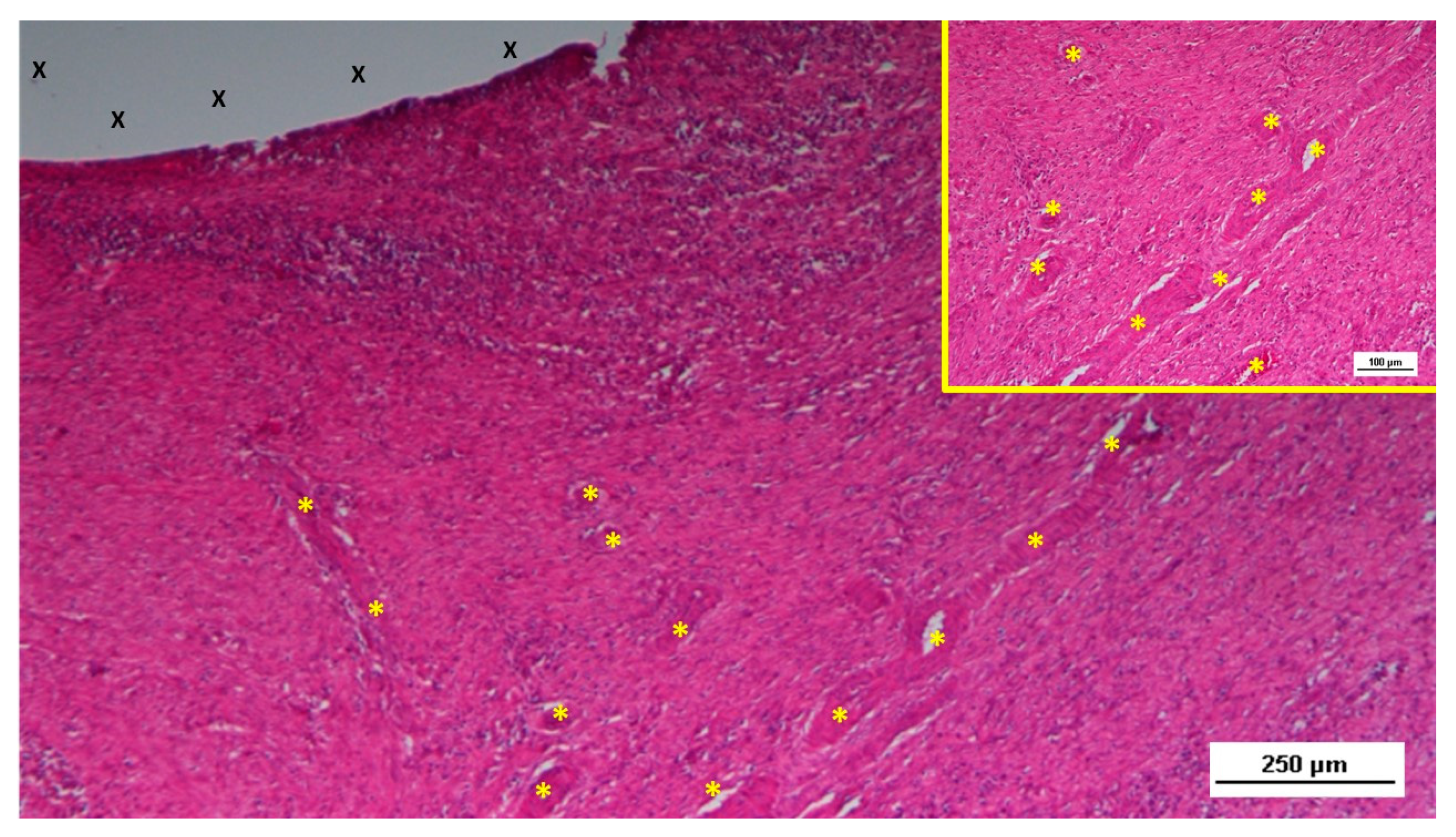
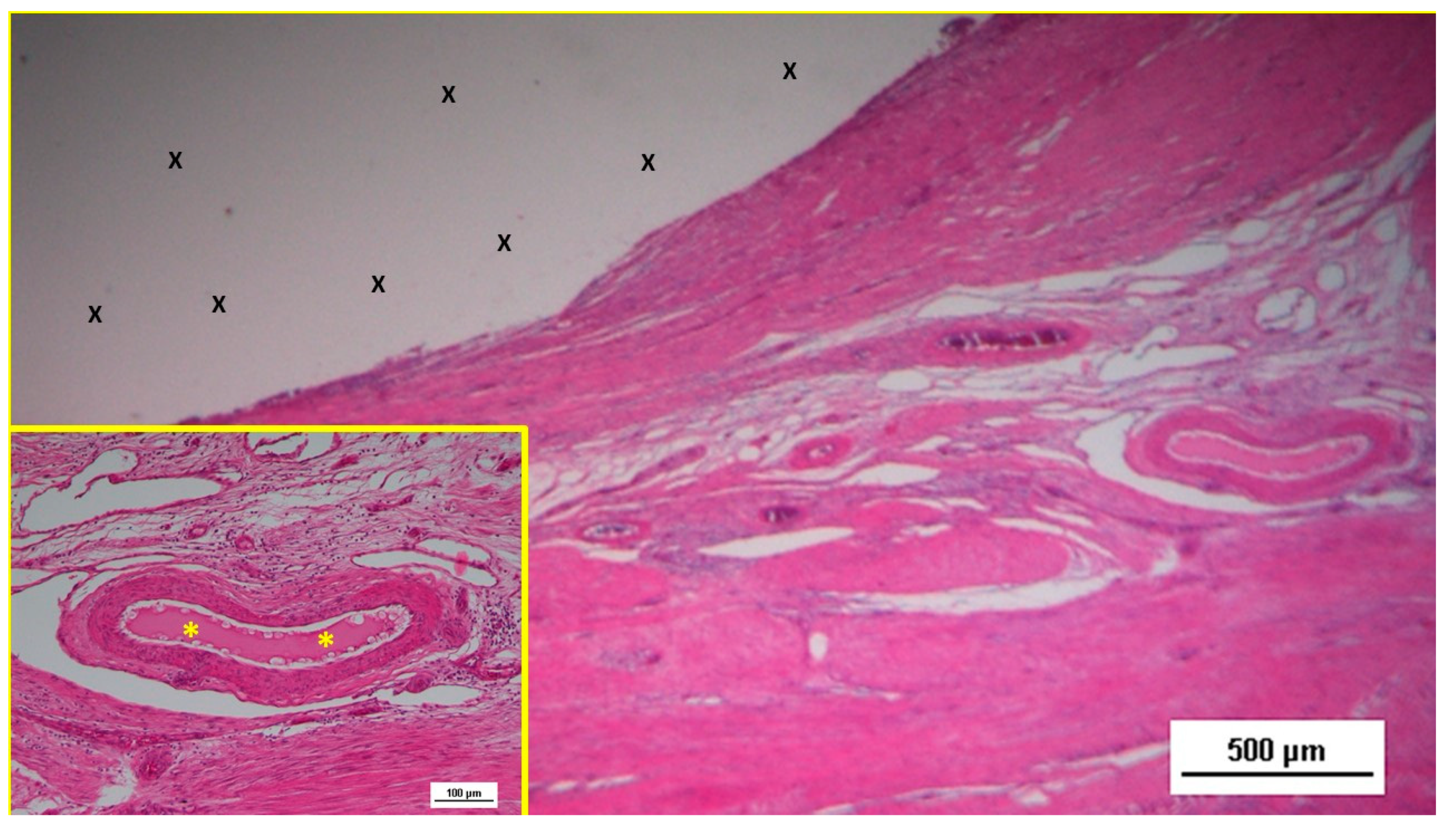
Figure 4.
Biopsy taken five weeks post-implantation from the 3D scaffold of the S&S device. Near the TPE fabric (X), no inflammatory reaction is present, but numerous vascular structures (*)—primarily immature veins—are visible. A yellow circle highlights a cluster of arterial elements in the early-stage of development. The inset (right upper corner) offers a detailed view of the arterial structures with developing muscular layers. HE 25X (main image) and HE 100X (inset).
Figure 5.
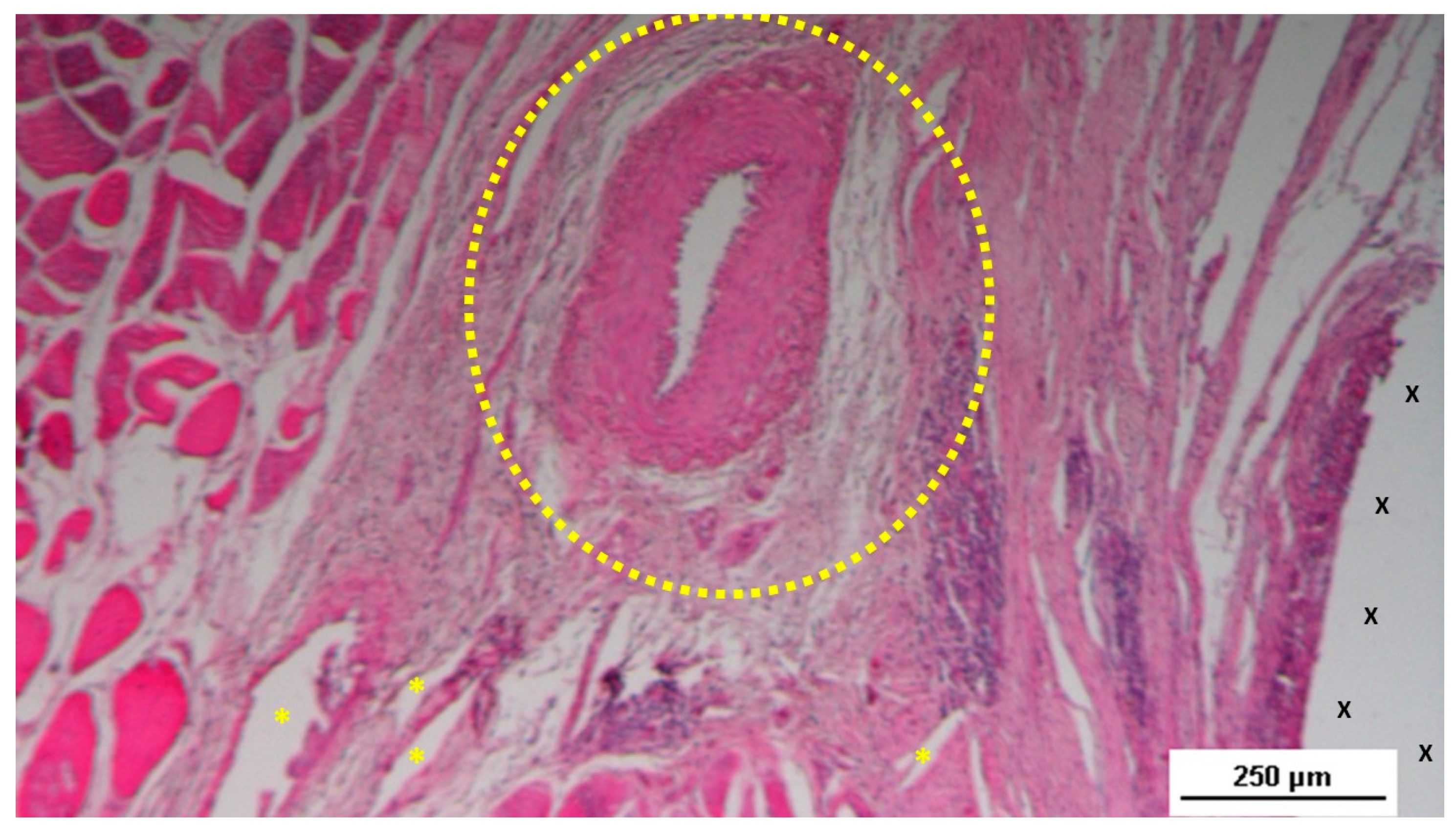
Biopsy sample from the 3D scaffold of the S&S device, excised four weeks post-implantation. Close to the device fabric (X), a large arterial structure (yellow circle) is seen in its early developmental stage. No inflammatory elements are detectable near the device. HE 25X.
Figure 5.
Biopsy sample from the 3D scaffold of the S&S device, excised four weeks post-implantation. Close to the device fabric (X), a large arterial structure (yellow circle) is seen in its early developmental stage. No inflammatory elements are detectable near the device. HE 25X.
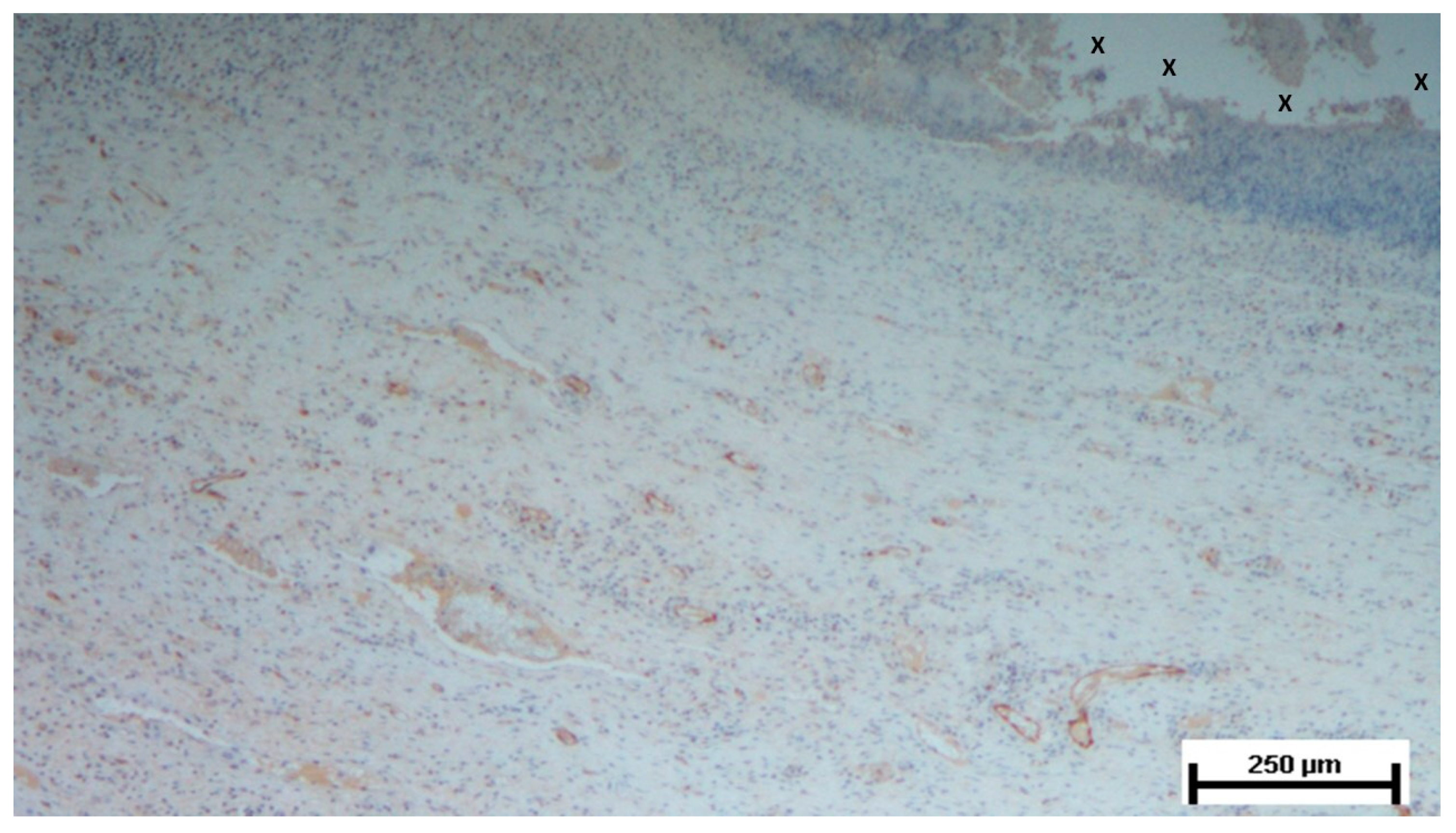
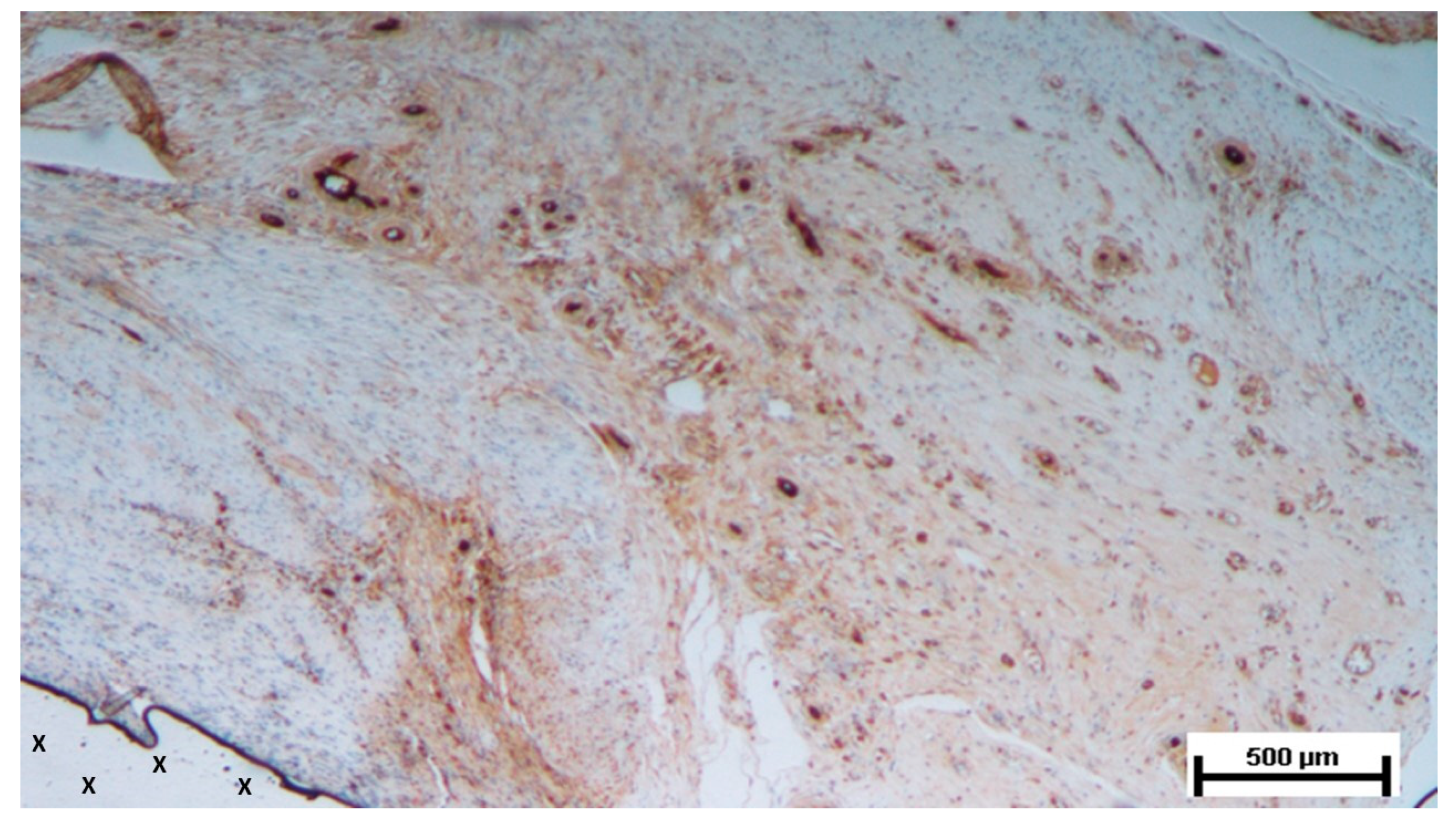
Figure 6.
Biopsy sample from the 3D scaffold of the S&S device, excised five weeks post-implantation. Close to the device fabric (X), several vascular structures (stained in brown) in the initial stage of development are visible in its early developmental stage. No inflammatory elements are detectable near the device. CD31 50X.
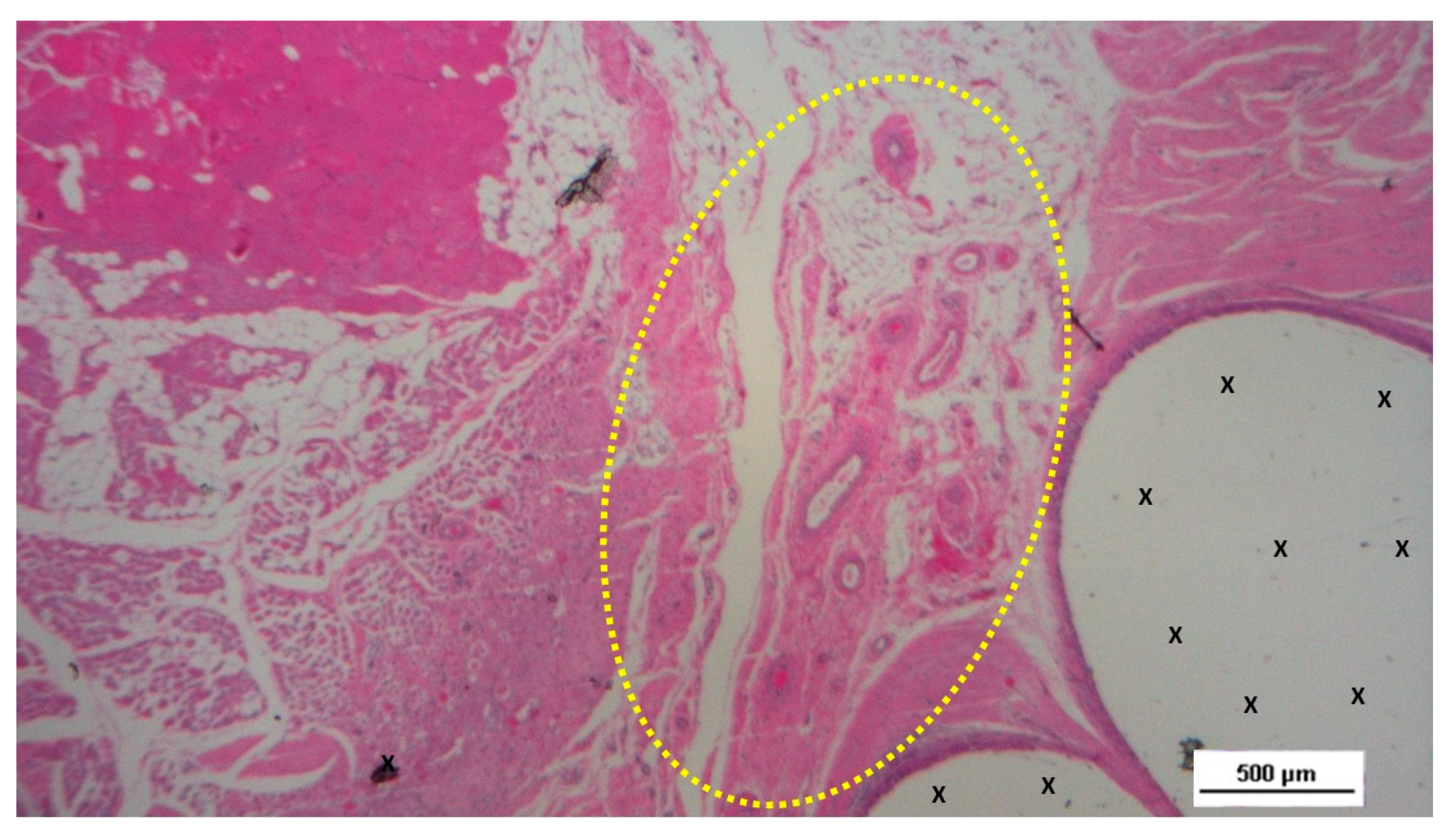
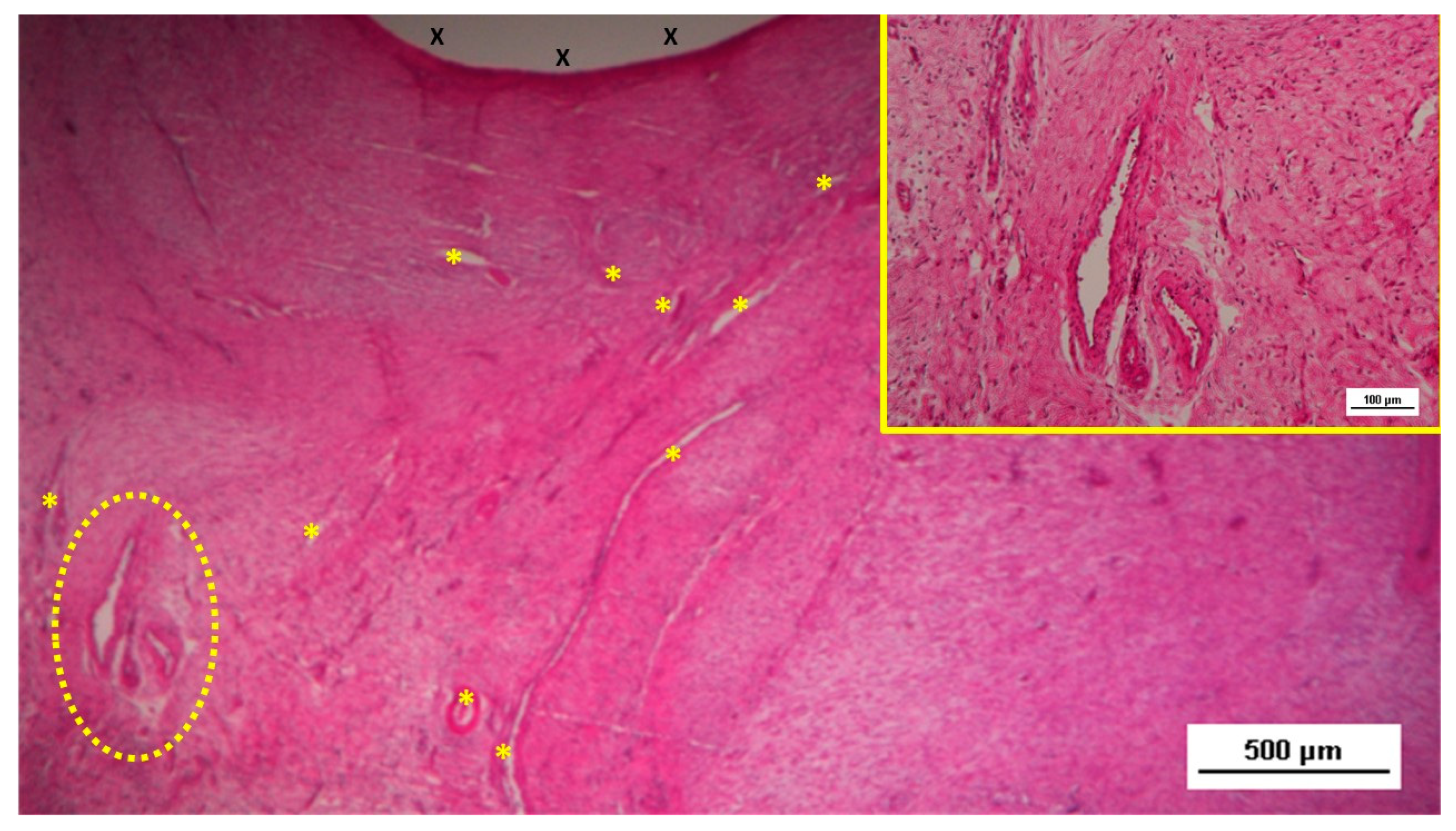
Figure 11.
Low-magnification microphotograph of tissue excised six months post-surgery, showing mature venous structures (white circular spots) and an artery (*) with thick media and adventitia layers, indicating completed structural maturation. The yellow circle encloses a mid-sized nerve. These structures are near the S&S scaffold fabric (X), which lacks inflammatory response. The inset (right upper corner) provides a highly magnified view of the thick arterial structure surrounded by veins (white spots) and the nerve (yellow circle). HE 25X (main image) and 100X (inset).
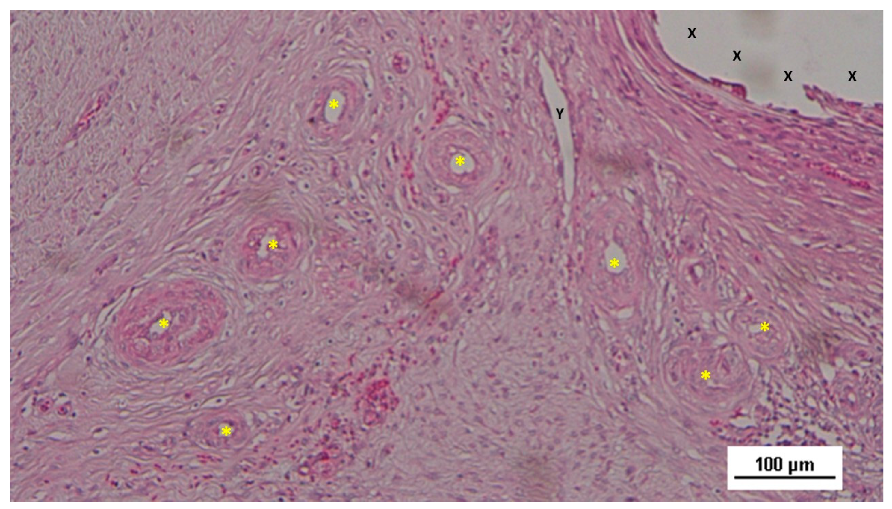
Figure 12.
Biopsy specimen from the 3D scaffold of the S&S device, six months post-surgery. In a matrix of slack, well-perfused connective tissue, several fully developed arterial structures (*) with thickened media are visible. A mature vein (Y) is located near the 3D scaffold fabric (X), which is free from inflammatory infiltration. HE 100X.
Figure 13.
Biopsy sample excised eight months post-implantation from the 3D scaffold of the S&S device. Adjacent to the S&S scaffold fabric (X), a large, well-developed artery (yellow circle) with a thick muscular layer and healthy endothelium is visible. Some veins (*) and numerous mature muscle bundles (red spots) are also evident. HE 50X.
Figure 14.
Biopsy sample excised six months post-implantation from the 3D scaffold of the S&S device. The microphotograph shows multiple arterial structures (targeted elements) and veins (white spots) within a slack connective matrix, situated between two areas of muscle tissue (red-stained). No inflammatory reaction is evident near the S&S device fabric (X). The inset (lower left corner) provides a magnified view of an artery, displaying all three mature layers with a blood-filled lumen (*). HE 25X (main image) and 100X (inset).
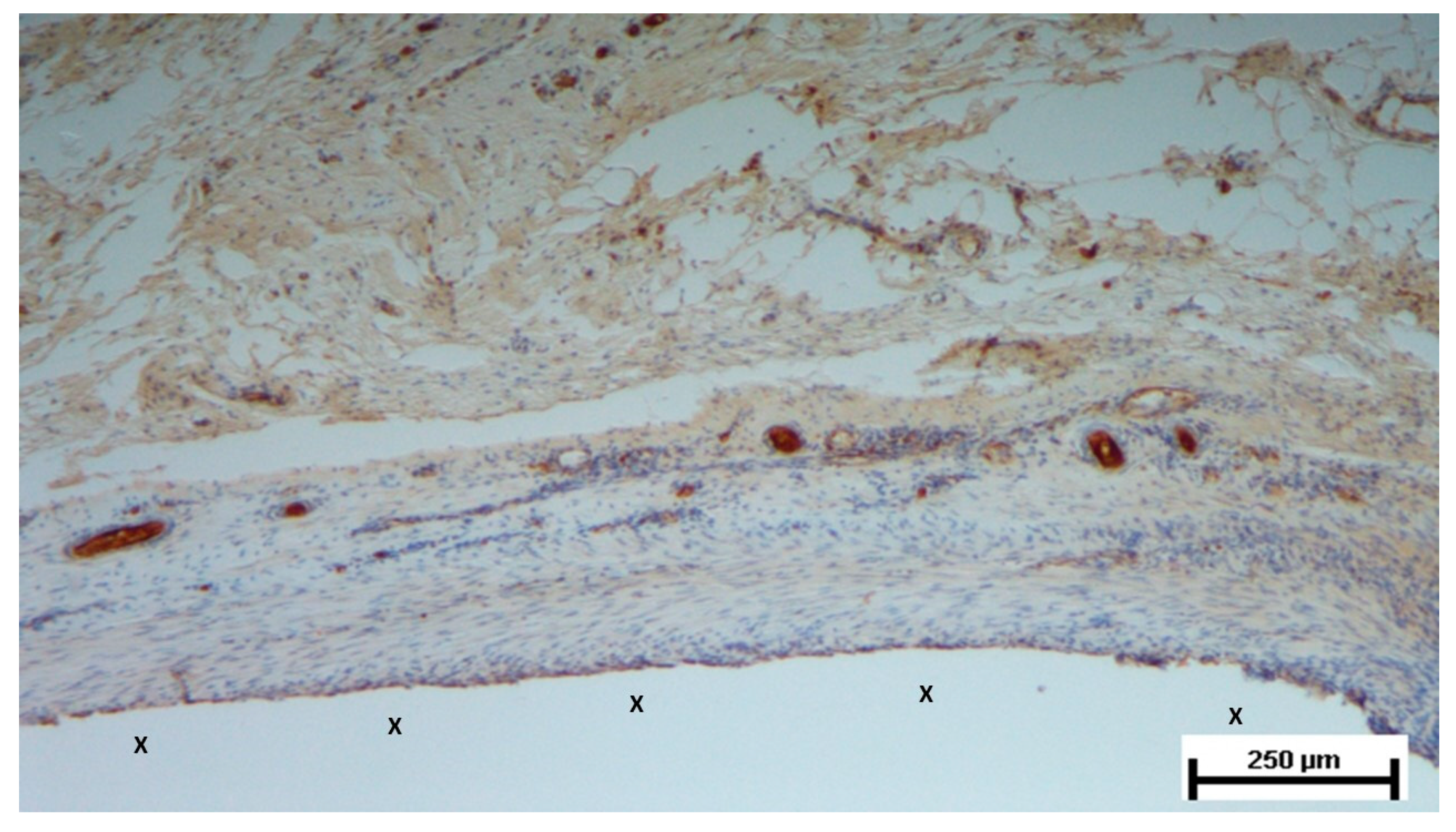
Figure 15.
Biopsy taken six months post-implantation from the 3D scaffold of the S&S Hernia System. Plenty of vascular elements showing fully mature structural arrangement (stained in brown), close to the S&S fabric (X). CD31 25X.
Figure 15.
Biopsy taken six months post-implantation from the 3D scaffold of the S&S Hernia System. Plenty of vascular elements showing fully mature structural arrangement (stained in brown), close to the S&S fabric (X). CD31 25X.
Table 1.
Technical properties of the TPE material used for the injection molding of the Stenting & Shielding Hernia System.
Table 1.
Technical properties of the TPE material used for the injection molding of the Stenting & Shielding Hernia System.
| TPE technical properties |
Value |
Unit |
Test Standard |
| ISO Data |
| Tensile Strength |
16 |
MPa |
ISO 37 |
| Strain at break |
650 |
% |
ISO 37 |
| Compression set at 70 °C, 24h |
54 |
% |
ISO 815 |
| Compression set at 100 °C, 24h |
69 |
% |
ISO 815 |
| Tear strength |
46 |
kN/m |
ISO 34-1 |
| Shore A hardness |
89 |
- |
ISO 7619-1 |
| Density |
890 |
kg/m³ |
ISO 1183 |
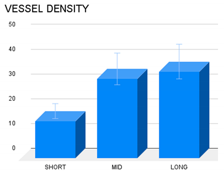
Table 2.
Vessel density in different temporal stages: short-, mid- & long-term. In long and mid term periods, the density of the vascular structures was greater compared to the short-term, being the difference among short- and long-term worth of note (p<0.05).
Table 2.
Vessel density in different temporal stages: short-, mid- & long-term. In long and mid term periods, the density of the vascular structures was greater compared to the short-term, being the difference among short- and long-term worth of note (p<0.05).
|
Disclaimer/Publisher’s Note: The statements, opinions and data contained in all publications are solely those of the individual author(s) and contributor(s) and not of MDPI and/or the editor(s). MDPI and/or the editor(s) disclaim responsibility for any injury to people or property resulting from any ideas, methods, instructions or products referred to in the content. |
© 2024 by the authors. Licensee MDPI, Basel, Switzerland. This article is an open access article distributed under the terms and conditions of the Creative Commons Attribution (CC BY) license (http://creativecommons.org/licenses/by/4.0/).