
Submitted:
29 November 2024
Posted:
02 December 2024
You are already at the latest version
Abstract
The daily well-being of modern civilization is closely linked to the use of various devices oper-ating by means of various sources related to the conversion, transfer and transmission of elec-tromagnetic (EM) energy. The exercise of these tools displays projected results, which are regu-larly concomitant with unsolicited side effects. A laudable management objective is to reinforce the desired results and reduce the unwanted effects. This contribution aims, within the frame-work of such management, to assess the importance of the approaches of Responsible Attitude (RA) and One Health (OH) in the daily practice of wireless EM energy devices involved in smart city (SC) environment. The RA approach is related to devices eco-design, while the OH concept is connected to SC biodiversity and ecosystem protection. Unsolicited side effects in these wire-less procedures could involve exposure to stray or radiated EM fields on apparatuses or living tissues. This contribution focused in particular on two instances involved in the SCs environ-ment. The first concerns, the disruptive effects of EM noise on, onboard or near-living tissues, detection and support medical tools. The second is related to the biological effects of wireless inductive power transfer, for batteries charging, aboard electric vehicles while stationary or running, in SCs. The investigations pursued in the article are assisted by examples of literature.
Keywords:
electromagnetic
; energy transfer and transmission
; Responsible Attitude
; One Health
; urban ecology
; living tissues onboard tools
; wireless battery charging
; electromagnetic noise
; adverse biological effects
1. Introduction
Throughout history, human civilization has sought to improve its well-being, including comfort, health, and safety. This has been achieved through various innovations in dedicated tools and the use of natural resources. These tools operate by using different available energy sources. For several decades, electromagnetic (EM) energy has found an important place, increasing over time. This energy has been obtained from the conversion of different resources, mainly fossil fuels. For some decades, human well-being has been considered to be associated with the ecosystem and biodiversity in an ecological context. This can be achieved through the use of clean energy for conversion into EM energy and the eco-design of EM tools, which corresponds to a sustainable use of these tools. Thus, performance is increased, energy is saved and harmful side effects for humans in their biodiversity and ecosystem environment are reduced; these elements reflect the Responsible Attitude (RA) approach. Indeed, the exercise of EM tools presents projected results, which are regularly concomitant with unsolicited side effects. These hostile effects involve exposure to stray and radiated EM fields (EMFs) that could disrupt various devices, including health devices as well as producing adverse biological effects (BEs) in all exposed living tissues involved in biodiversity; this exhibits the One Health (OH) approach [1,2].
In the urban ecological context, the above-mentioned disturbances provoked by the side effects related to exposure to EMFs, which could originate, for example, from wireless communication, e.g., [3], mobility e.g., [4], or energy transfer devices [5,6] widely used in daily life. Different categories of exposures are related to systems involving the wireless transfer or transmission of energy. These are related to the transfer distance, the amount of power transferred, the frequency of the EMF involved and the nature of the exposed object and its position. For hand-held wireless telecommunications tools such as mobile phones, they involve small high-frequency powers, radio frequency (RF), and may be close to the exposed object. The exposure in this case is focused in a small area of the exposed object. For mobile phone antenna towers, they involve higher powers but far from the exposed objects and the exposure is homogeneous [7,8] or overall on the exposed object [9]. In the case of wireless inductive power transfer (IPT), it is a wide power range, from a few watts for charging batteries of small household tools [10,11] to a few kilowatts in the case of electric vehicles (EVs), cars, trucks, buses, boats, etc. [12,13], the transfer distance is small (from a few mm to a few cm) and a low frequency (up to 200 kHz). The object possibly disturbed and exposed (to stray fields) could be at a distance of (a few cm from the small tools, about one m from those on board the EVs). As mentioned earlier, exposure to EMFs from wireless power transport in general can disrupt different objects. These disturbances could be related to living tissues in general (including biodiversity). Such disturbances could directly cause BEs in tissues or indirectly impair the functioning of tools onboard living tissues.
This contribution aims to assess the importance of RA and OH approaches in managing the improvement of expected results and the reduction of undesirable effects, in the daily practice of wireless EM energy transfer and transmission devices in the context of smart cities (SCs). The following sections of the contribution will analyze and illustrate such management. Section 2 summarizes the different disturbance effects of EMF exposure, in the non-ionizing frequency range, on different devices and living tissues. Section 3 concerns the roles of RA and OH approaches in EMF management in wireless EM devices. Section 4 concerns the physical phenomena and the governing mathematical equations related to the design of an EM device and the evaluation of the side effects of radiated EMFs. Section 5 is devoted to two applications of wireless energy transfer and propagation devices used in the urban environment of SCs. These are disturbances due to EMF radiation from wireless communication devices on near or onboard living tissue tools, and tissue BEs due to wireless IPT for batteries charging aboard EVs. Sections 6 is devoted to discussion involving additional details of matters relative to precedent sections and possible evolutions in the topic. The different analyses pursued in the article are supported by examples of literature.
2. EMF Exposure Perturbation Effects
In diverse circumstances, EMFs are expended daily in numerous cordial commitments. Moreover, they are engaged effectively in medical actions. Contrariwise, when such fields are activated unintentionally, they may yield negative effects. The exposure to such fields could disturb apparatuses functioning and provoke adverse BEs in living tissues. Such concerns are closely allied to the nature of the field and the radiated matter. The field intensity and frequency characterize EMF, while the material and structural assets depict matter. The effects of EMF radiation can be divided into two sets as regards the ranges of frequency. One covers the 103–1014 Hz range shared into radio, microwaves and infrared waves that yield non-ionizing exposure, while, the second concerns the 1015–1022 Hz range split into ultraviolet, X and gamma rays that fashion ionizing radiation. In this last range, field radiation on living tissues would likely cause serious adverse health effects by generating tissue harm. EMFs in the non-ionizing class operate safely in frequent circumstances but can also provoke adverse effects for excessive field strengths and exposure durations.
Wireless energy transfer and propagation devices involve non-ionizing EMF exposures in the ranges respectively of, low frequency less than 200 kHz and RF, 105–3. 1011 Hz. Two categories of EMF exposures related to the distance between the source and target. In the first, the source is close to the target interacting in a near field mode focused in a point of the target, while in the second, the source is distant (approximately higher than a wavelength for RF) generating a whole target homogenous far field exposure (see section 6 for more details). The interaction of the field and the target is dependent on the strength and frequency of the field, the exposure duration and properties of the target matter.
In the case of living tissues targets, the degree of EMF exposure is evaluated by the tissue specific absorption rate (SAR) in W/kg. This power density indicates the level of dissipated energy and its conversion to heat in a given exposure duration. This thermal outcome corresponds to the actual thermal BE of living tissues due to EMF exposure. The safety standards fixed limits for EMF exposures correspond to the SAR, consequent temperature rise and EMFs induced in the living tissues. Such thresholds are established function of the specifications of the source and tissue as well as the exposure circumstances and duration. Such data designate the specific part of tissue, the quality of the exposed subject (human, animal, plant, etc.), the nature and duration of the exposure for the different situations of the subject exposed related to its link with the source (fabricator, consumer, user, nearby, etc.). Excessive field strengths and exposure durations could produce high SAR and disproportionate temperature rise leading to adverse non-thermal BEs. These can trigger molecular disturbances guiding to tissue damage [14,15,16,17,18,19]. Additionally, fortuitous EMF exposures in the range of ionizing frequency can cause dangerous adverse effects allied to molecular disorders triggering tissue damage, because of the high energy of photons or particles.
In the case of target devices, which are usually protected against EMF radiation by the manufacturers’ safety regulations, the constancy of a device can be verified via an EM compatibility (EMC) analysis. In case the operation of the device uses EMF, exposure to external field radiation or the introduction of EM-sensitive materials could disturb the device own EMF and thus its constancy and reliability. Such effects would be amplified in medical devices operating in proximity to or embedded in tissues. Typical examples are static fixed-function onboard sensing tools [20,21,22,23,24,25,26,27,28,29,30], active organ stimulation tools [31,32,33,34,35], and magnetic resonance imaging (MRI) scanners used in guided therapies and interventions [36,37,38,39]. An EMC analysis is necessary to confirm the consistency of these medical tools disturbed by an external field or interfering substances [40,41].
3. RA and OH Approaches in Management of EMFs
The RA and OH approaches are directly linked to the sustainable design of a target or source device, associated with the object to be protected. Thus, a target corresponding to a living tissue onboard tool at risk, or a functional device acting as a source directly radiating threatened living tissues. In the latter case the optimization aims to improve the overall performances such as efficiency, power factor, etc. and to reduce the disturbing parasitic radiations. These two aspects of optimization, reinforcing the expected behavior and minimizing the undesirable side effects, added to the operational supervision of the device, are largely related to the RA and OH approaches and clarify their alliance [42]. The operational supervision of the device includes the planning of operations, which enables the sustainability associated with clean (carbon-free) energy use and economical pricing [43]. In fact, EM energy is deliberately considered as strictly clean if it comes from a clean energy conversion means. The above-mentioned disturbances related to parasitic EMF radiation could alter the operation of the exposed devices or produce BEs in the radiated tissues [41,42]. These adverse effects can be circumvented in two ways: via a sustainable design of the device components or through shielding technologies. Such shields are placed on the interface of (between) the radiation source and the exposed device or tissue. It should be noted that the electrical conductivity and/or permittivity (according to the involved frequency) of the materials of the device components are closely related to the disturbances of EM radiation. Such sensitivity to EMFs could be decreased by choosing materials corresponding to trivial conductive or dielectric behavior in the construction of a target device. Moreover, to ensure the constancy of the field distribution in MRI scanners, the materials inserted into their scaffold should be free of magnetic and conductive materials, thus avoiding EM noise, which can deteriorate the image due to artifacts [39,40].
It should be noted that where sustainable design and shielding would be impossible or insufficient to circumvent the harmful effects of EMF, the RA approach should be managed, in addition to device designers and manufacturers, by users involved in biodiversity and with decision-making capacity (i.e., public authorities) regarding modes of use. Precautions should therefore be taken by monitoring spaces involving EMF radiations (see for example section 5.2.4.) or by establishing restricted areas without radiation sources.
4. Physical Phenomena and Ruling Equations
The phenomena ruling the design of an EM device are related to EM and electric circuit domains. The phenomena implicated in the side effects of device-radiated EMF are likewise related to EM and heat transfer (HT) spheres. Actually, the interaction of EMFs radiated by a wireless EM device with matters crops undesirable thermal effects, which are governed by the EM and HT phenomena, coupled via the dissipated EM power (Pd) in these matters. In the instance of EMF exposure to living tissues, a bio heat (BH) phenomenon will rule the BEs and the temperature elevation created by a heat source Pd. These stated phenomena are governed by conforming mathematical equations, which are displayed in the following sections.
4.1. Governing Equations
Founded on Maxwell’s microscopic local behavior, the differential form of the general EMF four equations [44] is given by:
∇ × E = −∂t B (Maxwell—Faraday)
∇ × H = σ E + ∂t D (Maxwell—Ampère)
∇ · D = ρe (Maxwell—Gauss)
∇ · B = 0 (Maxwell—Thomson)
The HT equation in its differential form is given by:
c ρ ∂T/∂t = ∇ · (k ∇T)
In the case of EMF exposure of living tissues or devices, the EMF harmonic fields, the BH, and heat source Pd equations are given as follows:
∇ × H = J
J = Je + σ E + j ω D
E = −∇ V − j ω A
B = ∇ × A
c ρ ∂T/∂t = ∇ · (k ∇T) + Pd + Pt + cf ρf pf (Tf − T)
Pd = ω · ε″ · E2/2
In the above Equations (1)–(11), H and E are the vectors of the magnetic and electric fields in A/m and V/m, B and D are the vectors of the magnetic and electric inductions in T and C/m2, A and V are the magnetic vector and electric scalar potentials in W/m and volt. J and Je are the vectors of the total and source current densities in A/m2, σ is the electric conductivity in S/m, ρe is the volume density of electric charges in C/m3, and ω is the angular frequency = 2πf, f is the frequency in Hz of the exciting EMF. The symbol ∇ is a vector of partial derivative operators. The symbol ∂t is the operator of the partial time derivative. The magnetic and electric comportment laws, respectively, between B/H and D/E are represented by the permeability μ and the permittivity ε in H/m and F/m. The parameters: ε″ is the imaginary part of the complex permittivity of the absorbing material, and ρ is the material density in kg/m3. E is the absolute peak value of the electric field strength in V/m, c is the specific heat of the substance in J/(kg °C), k is thermal conductivity in W/(m·°C), and T is the substance temperature in °C. The power dissipation in W/m3 given by Equation (11) relates to the foremost dielectric heating of EMF energy loss. Notice that the imaginary part ε″ of the (frequency-dependent) permittivity ε is a measure of the ability of a dielectric material to convert EMF energy into heat. The volume density of power dissipations given by Equation (11) will be used in the coupling of EMF and BH equations. In the case of living tissues, we consider a self-tissue heat source Pt, convective heat transfer via irrigating fluid of tissue, and external heat source related to the EMF exposure Pd . The quantities Pt and Pd are heat sources in W/m3, Tf, and T are respectively the fluid temperature and the local temperature of tissue in °C, and cf, ρf, and pf are respectively fluid, specific heat in J/(kg °C), density in kg/m3, perfusion rate in 1/s .
It should be noted that the source term in the EMF equations is the excitation current density Je = σ Ee = j ω De = j ω ε Ee. In addition, the SAR in dielectric materials (biological tissues) is equal to Pd/ρ in W/kg.
Note that Equation (11) relays to bio-heat tissues considering the EMF exposure. This expression is analogous to Penne’s bio-heat equation [45,46] related to animal living tissues, including convective heat transfer in blood. The sap fluid in plants plays the role of animal blood. Besides, Phloems and Xylems enclosing sap act the task of veins and arteries, inclosing blood. In Penne’s bio-heat equation, the term Pt in (11) is related to animal metabolic heat and corresponds to internal heat in plant tissues. In addition, the last term in (11) acts for convection fluid heat transfer related to animal blood or plant sap.
The analysis of an EM device, including electric circuits, is related to the EM domain, Equations (6)–(9), coupled to the circuit domain via a general circuit equation under the form:
v = 1/C. ∫ i dt + r i + l. di/dt + dΨ/dt + ᴕ
In (12), v is the source voltage, i is the circuit current, r is the total circuit resistance, l a linear inductance, C a capacitance, ᴕ a non-linear voltage drop (e.g., a semiconductor component) in the electrical circuit and Ψ the flux linkage. The equations describing the EM and circuit domains to be solved are therefore (Equations (6)–(9) and (12)).
4.2. Numerical Solutions
The solution of the diverse equations relative to the EM, BH and electric circuit domains, (6-9), (10) and (12) respectively, should account for specific characteristics of involved structures. These are geometrical complexity, inhomogeneity of matter, nonlinear behaviors of variables and domains interdependence, which imply sophisticated computational strategies [47]. Satisfying such attributes inflicts material local solution suggesting the employment of discretized 3D techniques as finite elements method (FEM) or equivalent methods [48,49,50,51,52,53,54,55] concomitant to appropriate equations coupling schemes. Thus a weak coupling (iterative, due to distant time constants) of EM and BH domains would be practiced through (11). In case of electric circuit domain consideration, the coupling with EM one would be strong (simultaneous, due to close time constants) [56,57].
5. Applications of Wireless EM Energy Transfer and Propagation in SCs
In this section, we will consider two applications of systems involving wireless energy transfer or propagation. The first, which is related to healthcare, investigates the perturbations due to EMF radiations from wireless communication devices on targets of near or onboard living tissues medical tools intended for sensing or supporting duties. The analysis is related to such tools for their sustainable design permitting their protection against EMF radiation. In the second, which is connected to electric mobility [58], the analysis of a wireless IPT, for batteries charging aboard EV, considering its sustainable design allowing the reduction of its stray fields BEs in living tissues. In both cases, the involved living tissues are relative to urban SC biodiversity involving humans (adults and children), animals (domestic and wild), birds, aquatic creatures, insects, plants (ornamental and wild) and all other members of SC biodiversity. Moreover, these applications are belonging to connected remote strategies [59]. In the case of connected SCs, the two applications related to healthcare and mobility could be managed via their connections through the SC network [60].
5.1. Near and Onboard Living-Tissues Tools in SC Enviorement
Onboard tools are utilized in shapes of portable, detachable or integrated, which can execute inactive or active actions. Their deeds are placed in living tissues in general urban biodiversity. They can perform a detecting task as e.g., examination, predicting, etc. [20,21,22,23,24,25,26,27,28,29,30] or assistance job as e.g., support, invigorating, drug release, etc. [31,32,33,34,35] and scanners involved in image-assisted medical therapies and interventions [36,37,38,39]. These two burdens could be distinct or linked and distantly piloted or self-ruling. Thus, such tools generally require permanent real-time inside and outside elegant interactions. Additionally, their required operational power could be integrated or distantly transmitted [61]. Moreover, remote data communication routines are essential for the intelligent operation of onboard tools using wireless transmission or other remote sensing strategies such as satellite for observation, monitoring and management of biodiversity in general [62].
The detecting devices (sensors) are generally non-intrusive portable or detachable functioning in real-time allowing continuous observation of the involved tissue and therefore provide appropriate health information to deduce its comprehensive state and, furthermore, early health picture appraisal. Further personalized concerns related to disrupts of vital occupations as rate of respiration, pressure of fluid circulation, etc. could be identified via detachable smart tools.
The supporting tools are of two categories implanted in the tissue (for health maintenance and organs stimulation) or containing the tissue (for image-assisted therapeutics). The first are pumps, tissue stimulators, pacemakers, implanted cardioverter defibrillators etc., while the second are imaging scanners containing living tissue parts concerned by surgical or implanted drug release procedures [36,39].
In addition, the detailed above tasks of observation, prediction, support, stimulation, etc. of onboard tools, these also permit the management of post cure conditions in circumstances of previous disorders. Thus, circumventing transpositions, displacements, relocations etc. and substituting face-to-face care by an integrated connected support approach.
5.1.1. Onboard Tools Urban SC Perturbations Due to EMF Radiations
Exposures to external EMFs have diverse consequences on onboard tools, including impairment of their function and possible heating, which can increase the temperature of the living tissues involved. Thus, both categories of adverse effects can be critical contingent on the nature of the organ being monitored. For example, organ fluid circulation rate, organ vital role, the tool task in the organ, etc. Figure 1 demonstrates the interaction of EMF exposure with the tool design, duty and its exposure side effects on biodiversity (OH approach) [41].
5.1.2. Onboard Tools Sustainable Design
As mentioned in section 3, EMF perturbations of an onboard tool could be circumvented through eco-design either by managing its constituents or via shielding equipment. Thus could be achieved by avoiding EMF-sensitive matters in tool ingredients otherwise shields should be used. Simple conductor shields could be employed when their heating do not produce temperature rise of adjacent living tissues otherwise an amendment of the shielding conductive nature is needed. Thus, the use of multifunctional matched shield constituents permitting low-reflectivity shields lessening the strong field reflection triggered by the high substance conductivity [63,64,65,66,67,68]. The outcome of such eco-design involving RA and OH approaches permits a sustainable onboard tool with diminished adverse EMF effects. Figure 2 clarifies the weight of eco-design comprising RA and OH approaches through the design or shielding of onboard tool considering whole biodiversity by supervising hostile urban SC EMF effects.
5.1.3. Case of Image-Assisted Medical Therapies and Interventions Tools
Disorders in the distribution of the RF magnetic field inside an MRI tunnel, which is image-correlated, are characteristically activated by external EMFs or by the insertion of conductive or magnetic stuffs into the imager scaffold. In MRI-assisted interventions or therapies, only actuating tools fabricated from non-conductive and non-magnetic ingredients such as piezoelectric matters are tolerable. In general, piezoelectric actuators [69,70,71,72,73] employ for their excitation, thin conductive electrodes. The positioning of such electrodes regarding the field orientation performs an important character connected to the influence of the conductive surface perpendicular to the field direction; thus, the higher this surface, the higher the corresponding disturbance will be. Such occurrence that is related to currents induced, could be exploited in the actuation context to diminish disorder in the distribution of RF field [36]. The checking of such field distribution could be achieved via EMC analysis by solving equations (6-9) and comparing the field distributions without and with the introduced matter. Figure 3 displays the RF magnetic field distribution (vertically directed) in the axial section of the birdcage inside the tunnel of MRI, at 63.87 MHz (corresponding to static magnetic field B0 of 1.5 T), for the no material case. Figure 4 exhibits an example of a cubic piezoelectric material with relative values of (µ, and ε) and σ of (µr = 1, εr = [450990990], σ = 0 S/m) coated by thin electrodes on two opposite faces with (µr = 1, εr = 1, σ = 3.77 × 10⁷ S/m)—see Figure 4a. Figures 4b and 4c show the field distributions in the two situations where the electrodes are respectively perpendicular and parallel to the field direction. The effect of the conductors, in the last case (parallel to the field), is drastically reduced (Figure 3 and Figure 4c are almost identical). These results illustrate a simple qualitative example related to RA material use avoiding adverse effects due to possible EMF noise image perturbation.
5.2. IPT Batteries Charging in EVs in SCs
A typical case of decarbonized energy applications is related to the substitute of internal-combustion engine vehicles by EVs provided with batteries energy storage. This solution was thought in an ecological background for dropping air pollution and protecting global biodiversity and ecosystem, which are presently crucial. The energy storage batteries of these EVs at last will be wirelessly charged by IPTs in stationary and/or running modes. When replacing a long-established mode of transport to protect biodiversity and the ecosystem, it is necessary to ensure that the replacement solutions are consistent with such protection. Moreover, the building of these IPTs must expand a best ecology associated to clean energy economy. In such a framework, both RA and OH approaches will find their place in the design and control of IPT tools involved in SC environment.
5.2.1. Wireless IPT Structure
A wireless IPT charging tool is inserted between the power source and the battery load. The IPT central element responsible of wireless deed is an inductive coupler transformer (ICT) connected to the source and load through power electronics converters. The ICT that constituted of transmitter and receiver coils having inductances of L1 and L2, and parted by an airgap characterizing a mutual inductance M12. The airgap size reflects a weak coils coupling and hence the transfer of the required power implies a significant absorbed reactive power. So, the two coils are compensated by capacities C1 and C2. Thus, an IPT tool can perform, a galvanic split wireless power transfer, and a capacitive compensation permitting electronics connected to ICT to function at resonance. Such compensations on both sides of the ICT ensure consistent efficiency [74,75,76,77,78,79,80,81,82] and can use different topologies (series S and parallel P) contingent to the character of the load, such as for the two sides, SS, SP, PS, PP, etc. [75,82]. The SS compensation topology seems to be an economical option [81,82]. Magnetic ferrite sheets are usually employed coating the coils of the ICT, thus enhancing the transfer efficiency that is correlated to a better coupling coefficient. Figure 5 illustrates schematics of an IPT involving its ICT details. The IPT includes its ICT- ferrite sheets sandwiched between the grid, via an AC-DC-AC filtered adjusted frequency-voltage conversion, and the battery, via an AC-DC filtered conversion [42].
5.2.2. Wireless IPT Sustainable Design and Control
The RA approach in IPT sustainable design and control involves the featured and topology construction of the coils and ferrites of ICT, compensations, static convertors and filters. Thus, affecting better performance [74,75,76,77,78,79,80,81,82,83,84] through enhanced coupling and dropped stray fields [42,85,86] that controls the OH approach; this illustrate the junction of the two approaches. In addition, these two approaches are intimately connected, in addition to the IPT design, to the battery, state of charge estimation, and management [87]. Such management involves load planning (battery charging) control that enables sustainability connected to clean (carbon-free) energy use and economical pricing; see for example [43]. Actually, EM energy, as mentioned earlier, is deliberated rigorously clean if it originates of a clean energy conversion means [88,89]. 6 illustrates the two situations of unsustainable (a) and sustainable (b) designs of an IPT in urban context of SCs [42].
In the design and optimization of the ICT discussed in the last section (see Figure 5), the involved coupling coefficient k and the resonant frequency ωo (for coils SS compensation) are given by:
k = M12 · (L1 · L2)−1/2
ωo = (L1 · C1) −1/2 = (L2 · C2)−1/2
The ICT structure, outlined in Figure 5a, is presented in Figure 5c. It includes the coils, transmitter (on the ground), receiver (on the EV bottom), as well as the two magnetic ferrite plates covering the coils. Moreover, Figure 5c comprises a steel plate acting for the EV chassis. The coils of the ICT coupler with ferrites (pads) are parted by an air gap of (d) distance and (sh) coil axes shift. This structure will be considered in the design through equations (6-9) accounting for (13,14) via (12) in a strong coupled EM and electric circuit domains. The BEs in living tissues relative to induced fields and temperature rise could be determined by solving (6-9) with a source corresponding to stray field and (10) with a heat source Pd relative to (11). These EM and BH domains will be coupled in a weak manner.
5.2.3. RA and OH Approaches in SC Context
Wireless IPT charging of EVs is a SC-friendly answer, appropriate for shared and autonomous EVs, buses, trams, ships, medium-duty delivery trucks, drones, etc. IPT charging modes may be full static (in public stations or at home), full dynamic (electric roads), mixed dynamic-static mode, discontinuous electric roads or split static charging points. A full static mode corresponds to a limited range and requires high battery storage. A mixed dynamic-static mode is mostly suitable for highways and necessitates moderate battery storage. An intermittent dynamic mode matches partially fixed trajectory and entails low battery storage and is appropriate for public mobility with road portions with challenging charging infrastructures. The mode using distant static charging points relates to electric buses charging at their stops for which the battery storage depends on the number of stops, the distance and the static duration. All these charging modes entail security protections against EMF exposure.
RA and OH approaches intend, for the different charging modes, appropriate eco-design, clean energy use, reduction of harmful effects, risk evaluation and safeguard of biodiversity. Furthermore, the management of energy between the EV and grid might help RA; therefore, we can use control algorithms for grid-to-vehicle (G2V) and vehicle-to-grid (V2G) operating modes [90,91]. Additionally, it is required to guarantee interoperability of different IPTs (ground and vehicle sides) [82,92] and delivering a fitting charging profile allowing better RA [93]. Besides, connectivity and autonomous driving capability will make EVs much safer [94].
5.2.4. EMF Exposure, Charging Modes and Protection
The EMF exposure due to ICT stray fields is directly dependent of the 3D relative positions of its two coils (ground to vehicle sides) and hence strongly affected by the charging mode (static or dynamic) and the vehicle space positioning.
The consequences of such fields on living tissues are concomitant to their location in relation to the ICT position and the relative placing of its coils. The stray fields in dynamic charging mode are variable depending on the moving location of the receiver coil fixed at the EV bottom relative to the transmitter one fixed on the ground. In this case as well as the case of buses with distant static charging points, the concerned living tissues are those inside the EV in the passenger compartment. In such situations the protection of passengers could be achieved by shielding the vehicle upper part, over ICT, including the passenger compartment, this is an easy task using appropriate shape and material shields [5,63]. The passenger compartment in the case of static charging mode is normally empty, while for such a mode, the involved living tissues are those located outside the EV near the ICT under its bottom. These involve humans, animals, birds or plants, and could be affected by stray field exposure due to open space static charging. Such a mode is regularly exercised at home for personal EVs and at distant static points relate to electric buses charging at their stops. In these circumstances, the ICT shielding (in 3D geometry) is very problematic due to its configuration and position, partly on the bottom of the VE and in the ground. This problem is more difficult, for larger or more twisted air gaps corresponding respectively to the distances “d” or “sh” in Figure 5c. As such, these parameters are difficult to control, and therefore any element existence below or near the bottom of the EV must be avoided, especially for a significant duration. Thus, for the home charging case, this should be practiced only in enclosed places or encircled areas in the open space. For the bus stop charging case, the ICT should be located far from the bus entrance and the passenger waiting area.
5.2.5. Living Tissues BEs Control
The exposure circumstances painted above could be controlled and verified by solution of equations given in section 4 checking induced field values in living tissues matched to standards established thresholds [95,96,97,98]. For different charging modes, the previously mentioned routines must contain the specific geometry and matter properties of living tissue. Evaluation of living tissue EMFs exposure needs methods based on 3D computations to solve the EM domain (6-9) comprising the ICT system (Figure 5c) and the living tissue object (inside the vehicle or located nearby). Digital models (phantoms) regularly represent such living tissues. The significant features of such models are consistency of the physical-biological properties, the realistic state (shape) and the reliability with the numerical methodology used. Several models and matter characteristics related to living tissue could be found in the literature, e.g., for human tissues [99,100,101,102,103,104]. For human case, Figure 7 displays a structural body and its various organs and tissues [45].
5.2.6. Case of Exposure BEs in Human Body nearby an EV
A demonstrative example of ICT EMF exposure concerning the case of a human body placed on the ground horizontally adjacent to an EV while static charging mode is given in this section [45]. Figure 8 displays the induced field distributions (of B and E fields) in the body due to ICT EMF exposure. The utilized human body model for computations relates to the high-resolution human structural model, well matched with the numerical 3D FEM approach used, presented in Figure 7. The induced B and E fields in the body tissues have been computed from the solution of (6-9) with a source field corresponding to the stay fields of the ICT (3kW at 30 kHz). The results were matched to thresholds fixed by safety standards [95,96], (27 μT for magnetic induction B and 4.05 V/ m for the electric field E). In the preset case, results were in agreement with these safety guidelines.
6. Discussion
The analyses and examinations involved in this contribution demonstrated the significance of RA and OH approaches in the management of enriching projected outcomes and reducing adverse effects, in the daily practice of wireless EM energy transfer and transmission devices in urban smart cities context. Moreover, such management permitted also the protection against EMF exposure, of medical onboard tools as well as living tissues of humans and their urban environmental biodiversity and ecosystem. The RA and OH approaches were practiced via eco-design and monitoring involving human decision-making. The control of the different management actions (design, protection, control, risk evaluation, etc.) has been mastered and accomplished through governing physical involved phenomena and their mathematical equations treatments.
Following to the different analyses involved in the paper sections several points merit additional discussion.
- As discussed earlier, regarding EMF devices, a laudable management objective is to augment projected outcomes and reduce unplanned effects, thereby increasing device performance and protecting biodiversity and the ecosystem. These objectives could be achieved through RA and OH approaches. It should be noted that the more sophisticated the device, the greater its side effects will be. For example, a more powerful communication tool or a faster battery-charging device would produce higher radiated or stray EMFs, respectively. In such a case, the role of RA and OH approaches would be more crucial.
- Concerning the far field exposures (section 2), the definition of the far field region could approximately considered though the formula r′ > (2D2) / λ, where λ is the wavelength, D is the maximum dimension of a scattered matter in free space, and r’ is the far field distance. For example for a radiated body at frequency of 300 MHz (λ about 1 m), r′ is approximately for an adult human > 8 m, for a child > 1 m and for a cat > 0.2 m.
- The RA and OH approaches intend the managements of EMF perturbing source device as well as the targeted medical device. In the first, the goal is to reduce stray or noise fields, while in second the goal is to insure the device functioning and its shielding protection when necessary.
- In case of wireless charging batteries, theoretically the behavior of charging capacity versus running autonomy is approximately presented as follows: for a compensated IPT, neglecting losses, the transferred IPT energy = the batteries storage energy capacity = the running energy autonomy, thus Pt . Tt = nc . Cc = Pm . Tr , where Pt and Tt are the transferred power and charging time, nc and Cc are the number of battery cells and the battery cell storage energy capacity, Pm and Tr are the motor power and the running time. It is worth noting that for given, transferred power, motor power and a battery cell capacity, the charging time and autonomy time are correlated to the number of cells.
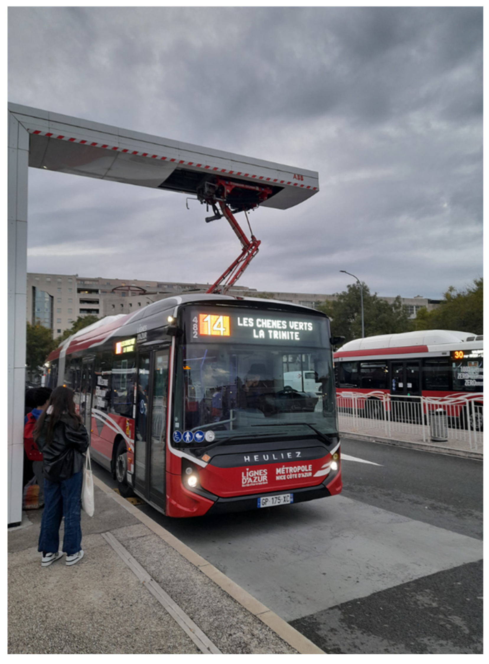
- In the case of charging a bus battery on an urban trajectory, the choice of charging routines must take into account not only the battery storage capacity, but also the infrastructure complexity and especially the exposure to harmful EMFs of living tissues involved in urban biodiversity. These routines can be at the day, circuit (round trip) or stop level. The corresponding distance autonomies will be all circuits of a day, one circuit or the distance between stops. Respectively, for these choices, the battery storage needs are significantly reduced and theoretically, when using an electric road (permanent source), the necessary storage is zero. Of course, the infrastructure complexities as well as the protection technologies are different for such routine options. The day or circuit level routines are without passengers. The case of a circuit charging routine could be a good compromise for battery storage, infrastructure complexity and exposure safety. In such a case, the ICT could be on the roof of the bus, as shown in Figure 9.
- In this contribution, the OH approach has often been mentioned. It emphasizes the interdependence of members of biodiversity “all for one and one for all” for the good of the ecosystem where they live. We have insisted on the fact that human well-being must not cause inconvenience to members of biodiversity including humans and even share this well-being. It is not a gift from humans to biodiversity and the ecosystem but just a return to them for their actions for the existence of humans. It is even enough to imitate them, like the action of pollinators (like bees) [105], hydrologists (like beavers) [106], etc. for their roles in the ecosystem. We can find even more alliances such as for example of certain viruses with their hosted organism (virus-host interaction); thus giving their hosts the ability to produce a toxin to destroy their competitors (as in the case of baker’s yeast) [107]. Other examples of interactions could be found, such as between bacteria and phytoplankton [108], or between certain microorganisms, plants and nutrient cycles [109].
- In applications related to onboard medical tools and wireless IPT mobility devices, sensors and actuators can be involved and a wireless sensor and actuator network (WSAN) can be used especially in a complex context. A WSAN is an assembly of sensors that collect data at their location and actuators interacting with them autonomously or wirelessly controlled. A WSAN realization point can encompass a mix of planned multi-actuation actions composed of sensors to perform more complex tasks. In fact, WSANs are increasingly used for health and medical care (on-site or remote), ecosystem monitoring and control, mobility, smart cities, etc. [110,111]. Such applications may contain high-level complexities that require adequate supervision. The presence of daily EM environmental disturbances in the vicinity of the concerned WSANs could threaten the operation of their components as mentioned before and the analysis of these disturbances in the context of complex scenarios always remains crucial.
- Regarding connectivity in a SC environment [112,113,114], in addition to connections with other SCs, the different SC platforms involving internal city administration, security, education, etc. could take into account healthcare and mobility boards [115,116,117]. Remote monitoring of the corresponding data of these boards could take into account the objective of the present contribution “Eco-management of wireless EM devices involved in SCs for healthcare and mobility”. This could be achieved by checking, the proper functioning of the tissues-onboard tools and the state of the EV battery, including its charging system (IPT parasitic radiation); thus protecting humans and their environmental biodiversity and ecosystem.
- To end on an encouraging tone, it should be noted that the harmful effects of EMFs discussed in this contribution are relatively different, for biodiversity and the ecosystem, from the effects of other current terrestrial pollutions (chemical, biological, etc.) that could be cumulatively irreversible or degradable in the very long term. For the harmful effects of recently emerged EMFs, it is sufficient to take the necessary precautions using the recommended approaches to promptly stop the effects of these pollutions.
Funding
This research received no external funding.
Data Availability Statement
No new data were created.
Conflicts of Interest
The authors declare no conflicts of interest.
References
- Mackenzie, J.S.; Jeggo, M. The One Health Approach—Why Is It So Important? Trop. Med. Infect. Dis. 2019, 4, 88. [CrossRef]
- Benis, A; Tamburis, O; Chronaki, C; Moen, A. One Digital Health: A Unified Framework for Future Health Ecosystems. J Med Internet Res. 2021, 23(2), e22189. [CrossRef]
- Elbasheir, M.S.; Saeed, R.A.; Ibrahim, A.A.; Edam, S.; Hashim, F.; Fadul, S.M. A review of EMF radiation for 5G mobile communication systems. In 2021 IEEE Asia-Pacific Conference on Applied Electromagnetics (APACE), 1-6. IEEE. Penang, Malaysia, December 2021. [CrossRef]
- Moro, S.; Linsalata, F.; Manzoni, M.; Magarini, M.; Tebaldini, S. Enhancing User Localization with an Integrated Sensing and Communication (ISAC) System: An Experimental UAV Search-and-Rescue Use Case. Remote Sens. 2024, 16, 3031. [CrossRef]
- Sagar, A.; Kashyap, A.; Nasab, M.A.; Padmanaban, S.; Bertoluzzo, M.; Kumar, A.; Blaabjerg, F. A Comprehensive Review of the Recent Development of Wireless Power Transfer Technologies for Electric Vehicle Charging Systems. IEEE Access 2023, 11, 83703-83751. [CrossRef]
- Shanmugam, Y.; Narayanamoorthi, R.; Vishnuram, P.; Bajaj, M.; AboRas, K.M.; Thakur, P. A systematic review of dynamic wireless charging system for electric transportation. IEEE Access 2022, 10, 133617-133642. [CrossRef]
- More, C.S; Markad, N.T. Performance Analysis of cell phone Towers Radiation. International Conference on Computing, Communication, and Intelligent Systems (ICCCIS), Greater Noida, India, 2022, 383-388. [CrossRef]
- Siddoo-Atwal, C. Electromagnetic Radiation from Cellphone Towers: A Potential Health Hazard for Birds, Bees, and Humans [Internet]. Current Understanding of Apoptosis—Programmed Cell Death. InTech; 2018. Available from:. https://doi.org/10.5772/intechopen.76084 (Accessed October 29, 2024). [CrossRef]
- Herssens, H. ; Toribio, D. ; De Borre, E. ; Thielens, A. Whole-body averaged absorbed power in insects exposed to far-field radio frequency electromagnetic fields. IEEE Transactions on Antennas and Propagation 2022, 70(11), 11070-11078. [CrossRef]
- Liu, Z; Li, T; Li, S; Mi, CC. Advancements and challenges in wireless power transfer: a comprehensive review. Nexus 2024, 1:100014. [CrossRef]
- Shah, IA; Zada, M; Shah, SAA; Basir, A; Yoo, H. Flexible metasurface-coupled efficient wireless power transfer system for implantable devices. IEEE Trans. on Microwave Theory and Techniques 2024, 72:2534−47. [CrossRef]
- brahim, M.; Bernard, L.; Pichon, L.; Razek, A.; Houivet, J.; Cayol, O. Advanced modeling of a 2-kw series–series resonating inductive charger for real electric vehicle. IEEE Trans. Veh. Technol. 2015, 64, 421–430. [CrossRef]
- Razek, A. Review of Contactless Energy Transfer Concept Applied to Inductive Power Transfer Systems in Electric Vehicles. Appl. Sci. 2021, 11, 3221. [CrossRef]
- Jazyah, YH. Thermal and Nonthermal Effects of 5 G Radio-Waves on Human’s Tissue. ScientificWorldJournal 2024, 3801604. [CrossRef]
- Wust, P.; Kortüm, B.; Strauss, U.; Nadobny, J.; Zschaeck, S.; Beck, M.; Stein, U.; Ghadjar, P. Non-thermal effects of radiofrequency electromagnetic fields. Sci. Rep. 2020, 10, 13488. [CrossRef]
- Hansson Mild, K.; Mattsson, M.-O.; Jeschke, P.; Israel, M.; Ivanova, M.; Shalamanova, T. Occupational Exposure to Electromagnetic Fields—Different from General Public Exposure and Laboratory Studies. Int. J. Environ. Res. Public Health 2023, 20, 6552. [CrossRef]
- Thoradit, T; Chabi, M; Aguida, B; Baouz, S; Stierle, V; Pooam, M; Tousaints, S; Akpovi, CD; Ahmad, M. Hypersensitivity to man-made electromagnetic fields (EHS) correlates with immune responsivity to oxidative stress: a case report. Commun Integr Biol. 2024, 17(1), 2384874. [CrossRef]
- McCredden, JE; Cook, N; Weller, S; Leach, V. Wireless technology is an environmental stressor requiring new understanding and approaches in health care. Front Public Health 2022, 10, 986315. [CrossRef]
- Abdul-Al, M.; Amar, A.S.I.; Elfergani, I.; Littlehales, R.; Ojaroudi Parchin, N.; Al-Yasir, Y.; See, C.H.; Zhou, D.; Zainal Abidin, Z.; Alibakhshikenari, M.; et al. Wireless Electromagnetic Radiation Assessment Based on the Specific Absorption Rate (SAR): A Review Case Study. Electronics 2022, 11, 511. [CrossRef]
- Guk, K.; Han, G.; Lim, J.; Jeong, K.; Kang, T.; Lim, E.-K.; Jung, J. Evolution of Wearable Devices with Real-Time Disease Monitoring for Personalized Healthcare. Nanomaterials 2019, 9, 813. [CrossRef]
- Liu, E.; Cai, Z.; Ye, Y.; Zhou, M.; Liao, H.; Yi, Y. An Overview of Flexible Sensors: Development, Application, and Challenges. Sensors 2023, 23, 817. [CrossRef]
- Mukhopadhyay, S.C.; Suryadevara, N.K.; Nag, A. Wearable Sensors for Healthcare: Fabrication to Application. Sensors 2022, 22, 5137. [CrossRef]
- Chakrabarti, S.; Biswas, N.; Jones, L.D.; Kesari, S.; Ashili, S. Smart Consumer Wearables as Digital Diagnostic Tools: A Review. Diagnostics 2022, 12, 2110. [CrossRef]
- Escobar-Linero, E.; Muñoz-Saavedra, L.; Luna-Perejón, F.; Sevillano, J.L.; Domínguez-Morales, M. Wearable Health Devices for Diagnosis Support: Evolution and Future Tendencies. Sensors 2023, 23, 1678. [CrossRef]
- Devi, D.H.; Duraisamy, K.; Armghan, A.; Alsharari, M.; Aliqab, K.; Sorathiya, V.; Das, S.; Rashid, N. 5G Technology in Healthcare and Wearable Devices: A Review. Sensors 2023, 23, 2519. [CrossRef]
- Pantelopoulos A, Bourbakis NG. A survey on wearable sensor-based systems for health monitoring and prognosis. IEEE Trans. Syst. Man Cybern. Part C 2010, 40, 1–12. [CrossRef]
- Ahmed, M.R.; Newby, S.; Potluri, P.; Mirihanage, W.; Fernando, A. Emerging Paradigms in Fetal Heart Rate Monitoring: Evaluating the Efficacy and Application of Innovative Textile-Based Wearables. Sensors 2024, 24, 6066. [CrossRef]
- Xing, Y; Yang, K; Lu, A; Mackie, K; Guo, F. Sensors and Devices Guided by Artificial Intelligence for Personalized Pain Medicine. Cyborg Bionic Syst. 2024, 13, 5, 0160. [CrossRef]
- Moon, K.S.; Lee, S.Q. A Wearable Multimodal Wireless Sensing System for Respiratory Monitoring and Analysis. Sensors 2023, 23, 6790. [CrossRef]
- Khan Mamun, M.M.R.; Sherif, A. Advancement in the Cuffless and Noninvasive Measurement of Blood Pressure: A Review of the Literature and Open Challenges. Bioengineering 2023, 10, 27. [CrossRef]
- Bhuva AN, Moralee R, Brunker T, Lascelles K, Cash L, Patel KP, Lowe M, Sekhri N, Alpendurada F, Pennell DJ, Schilling R, Lambiase PD, Chow A, Moon JC, Litt H, Baksi AJ, Manisty CH. Evidence to support magnetic resonance conditional labelling of all pacemaker and defibrillator leads in patients with cardiac implantable electronic devices. Eur Heart J. 2022, 43(26), 2469-2478. [CrossRef]
- Joo, H.; Lee, Y.; Kim, J.; Yoo, J.S.; Yoo, S.; Kim, S.; Arya, A.K.; Kim, S.; Choi S.H.; Lu, N.; et al. Soft Implantable Drug Delivery Device Integrated Wirelessly with Wearable Devices to Treat Fatal Seizures. Sci. Adv. 2021, 7, eabd4639. [CrossRef]
- Cheng, Y.; Xie, D.; Han, Y.; Guo, S.; Sun, Z.; Jing, L.; Man, W.; Liu, D.; Yang, K.; Lei, D.; et al. Precise management system for chronic intractable pain patients implanted with spinal cord stimulation based on a remote programming platform: Study protocol for a randomized controlled trial (PreMaSy study). Trials 2023, 24, 580. [CrossRef]
- Thotahewa, KMS; Redouté, J; Yuce, MR. Electromagnetic and thermal effects of IR-UWB wireless implant systems on the human head. In Proceedings of the 2013 35th Annual International Conference of the IEEE Engineering in Medicine and Biology Society (EMBC), Osaka, Japan, 3–7 July 2013, 5179–5182. [CrossRef]
- Gordon JS, Maynes EJ, O’Malley TJ, Pavri BB, Tchantchaleishvili V. Electromagnetic interference between implantable cardiac devices and continuous-flow left ventricular assist devices: a review. J Interv Card Electrophysiol. 2021, 61(1), 1-10. [CrossRef]
- Razek, A. Towards an image-guided restricted drug release in friendly implanted therapeutics. Eur. Phys. J. Appl. Phys. 2018, 82, 31401. [CrossRef]
- Velazco Garcia, JD; Navkar, NV; Gui, D; Morales, CM; Christoforou, EG; Ozcan, A; Abinahed, J; Al-Ansari, A; Webb, A; Seimenis, I; Tsekos, NV. A Platform Integrating Acquisition, Reconstruction, Visualization, and Manipulator Control Modules for MRI-Guided Interventions. J Digit Imaging. 2019, 32(3), 420-432. [CrossRef]
- Su, H.; Kwok, K.W.; Cleary, K.; Iordachita, I.; Cavusoglu, M.C.; Desai, J.P.; Fischer, G.S. State of the art and future opportunities in MRI-guided robot-assisted surgery and interventions. Proceedings of the IEEE 2022, 110(7), 968-992. [CrossRef]
- Razek, A. Image-Guided Surgical and Pharmacotherapeutic Routines as Part of Diligent Medical Treatment. Appl. Sci. 2023, 13, 13039. [CrossRef]
- Razek, A. Assessment of a Functional Electromagnetic Compatibility Analysis of Near-Body Medical Devices Subject to Electromagnetic Field Perturbation. Electronics 2023, 12, 4780. [CrossRef]
- Razek, A. Sustainable Design and Integrity Control of Onboard Health Tools for Humans and Their Environmental Urban Biodiversity. Intelligent and Sustainable Manufacturing 2024; 1: 10015. [CrossRef]
- Razek, A. One Health Ecological Approach to Sustainable Wireless Energy Transfer Aboard Electric Vehicles for Smart Cities. Energies 2024, 17, 4349. [CrossRef]
- Etxegarai, G.; Camblong, H.; Ezeiza, A.; Lie, T.T. Design of Three Electric Vehicle Charging Tariff Systems to Improve Photovoltaic Self-Consumption. Energies 2024, 17, 1806. [CrossRef]
- Maxwell, JC. VIII. A dynamical theory of the electromagnetic field. Philosophical Transactions of Royal Society 1865, 155, 459–512. [CrossRef]
- Razek, A. Biological and Medical Disturbances Due to Exposure to Fields Emitted by Electromagnetic Energy Devices—A Review. Energies 2022, 15, 4455. [CrossRef]
- Pennes, HH. Analysis of tissue and arterial blood temperatures in the resting human forearm 1948. Journal of Applied Physiology 1998, 85(1) 5–34. [CrossRef]
- Boules, N.; Douglas, K.; Feldman, S.; Fix, L.; Hager, G.; Hailpern, B.; Martial Hebert, M.; Dan Lopresti, D.; Beth Mynatt,B.; Rossbach, C.C.; et al. The future of computing research: Industry-academic collaborations. arXiv 2016, arXiv:1606.09236. [CrossRef]
- Nunes, A.S.; Chadebec, O.; Kuo‐Peng, P.; Dular, P.; Meunier, G. A Coupling between the Facet Finite Element and Reluctance Network Methods in 3-D. IEEE Transactions on Magnetics 2017, 53 (10). [CrossRef]
- Henrotte, F; Geuzaine, C. Electromagnetic forces and their finite element computation. Int J Numer Model. 2024, 37(5), e3290. [CrossRef]
- Antunes, O.J.; Bastos, J.P.A.; Sadowski, N.; Razek, A.; Santandrea, L.; Bouillault, F.; Rapetti, F. Comparison between nonconforming movement methods. IEEE Trans. Magn. 2006, 42, 599–602. [CrossRef]
- Bernard, L. Electrical characterization of biological tissues and computing of phenomena induced in the human body by electromagnetic fields below 1 GHz. PhD thesis, 2007. Universities of Ecole Centrale de Lyon, France and Universidade federal de Minas Gerais, Brazil.
- Ren, Z; Razek, A. Force calculation by Maxwell stress tensor in 3D hybrid finite element-boundary integral formulation. IEEE Transactions on Magnetics 1990, 26(5), 2774-76. [CrossRef]
- Tang, F; Giaccone, L; Hao, J; Freschi, F; Wu, T; Crozier, S; Liu, F. Exposure of Infants to Gradient Fields in a Baby MRI Scanner. Bioelectromagnetics. 2022, 43(2), 69-80. [CrossRef]
- Talleb, H; Ren, Z. A new nonlinear multiscale magnetostrictive approach for FEM modelling of magnetoelectric composites under magneto-thermo-elastic loading. Composite Struct. 2023, 303:116260. [CrossRef]
- Urdaneta-Calzadilla, A.; Chadebec, O.; Galopin, N.; Niyonzima, I.; Meunier, G.; Bannwarth, B. Modeling of Magnetoelectric Effects in Composite Structures by FEM–BEM Coupling. IEEE Transactions on Magnetics 2023, 59(5), 1-4, 7000604. [CrossRef]
- Gu, B; Li, H; Li, B. An internal ballistic model of electromagnetic railgun based on PFN coupled with multi-physical field and experimental validation, Defence Technology, Volume 32, 2024, Pages 254-261. [CrossRef]
- Razek, A. Coupled Models in Electromagnetic and Energy Conversion Systems from Smart Theories Paradigm to That of Complex Events: A Review. Appl. Sci. 2022, 12, 4675. [CrossRef]
- Boules, N. Electric Drives for Battery Electric Vehicles. Navigating an Electric Vehicle Future Virtual Workshop, October 25-28, 2021-The US National Academies of Sciences Electric Drives for Vehicles—National Academies of Sciences https://www.nationalacademies.org/documents/embed/link/LF2255DA3DD1C41C0A42D3BEF0989ACAECE3053A6A9B/file/D6B5A579A548566915FEC39CBDBB3EAF5E8933C796E8?noSaveAs=1 (Accessed July 29, 2024).
- Picozzi, P.; Nocco, U.; Puleo, G.; Labate, C.; Cimolin, V. Telemedicine and Robotic Surgery: A Narrative Review to Analyze Advantages, Limitations and Future Developments. Electronics 2024, 13, 124. [CrossRef]
- Pourroostaei Ardakani, S., Cheshmehzangi, A. Big Data Analytics and the Future of Smart Transport and Healthcare Systems. In: Big Data Analytics for Smart Transport and Healthcare Systems. Urban Sustainability 2023. Springer, Singapore. [CrossRef]
- Campi, T; Cruciani, S; Maradei, F; Montalto, A; Feliziani, M. Wireless Power Transmission for Left Ventricular Assist Devices: Advancements, Challenges, and Future Directions. 2024 IEEE Wireless Power Technology Conference and Expo (WPTCE), Kyoto, Japan, 2024, 505-508. [CrossRef]
- Pettorelli, N; Safi, K; Turner, W. Satellite remote sensing, biodiversity research and conservation of the future. Phil. Trans. R. Soc. 2014, B369, 20130190. [CrossRef]
- Quercio, M; Lozito, GM, Corti, F;. Fulginei, FR; Laudani, A. Recent Results in Shielding Technologies for Wireless Electric Vehicle Charging Systems. IEEE Access 2024, 12, 16728-16740. [CrossRef]
- Cheng, J; Li, C; Xiong, Y; Zhang, H; Raza, H; Ullah, S; Wu, J; Zheng, G; Cao, Q; Zhang, D; Zheng, Q; Che, R. Recent Advances in Design Strategies and Multifunctionality of Flexible Electromagnetic Interference Shielding Materials. Nanomicro Lett. 2022, 14(1), 80. [CrossRef]
- Ma, Z.; Deng, Z.; Zhou, X.; Li, L.; Jiao, C.; Ma, H.; Yu, Z.Z.; Zhang, H.B. Multifunctional and magnetic MXene composite aerogels for electromagnetic interference shielding with low reflectivity. Carbon 2023, 213, 118260. [CrossRef]
- Yun, J.; Zhou, C.; Guo, B.; Wang, F.; Zhou, Y.; Ma, Z.; Qin, J. Mechanically strong and multifunctional nano-nickel aerogels based epoxy composites for ultra-high electromagnetic interference shielding and thermal management. J. Mater. Res. Technol. 2023, 24, 9644–9656. [CrossRef]
- Verma, R.; Thakur, P.; Chauhan, A.; Jasrotia, R.; Thakur, A. A review on MXene and its’ composites for electromagnetic interference (EMI) shielding applications. Carbon 2023, 208, 170–190. [CrossRef]
- Zecchi, S.; Cristoforo, G.; Bartoli, M.; Tagliaferro, A.; Torsello, D.; Rosso, C.; Boccaccio, M.; Acerra, F. A Comprehensive Review of Electromagnetic Interference Shielding Composite Materials. Micromachines 2024, 15, 187. [CrossRef]
- Hariri, H; Bernard, Y; Razek, A. 2-D Traveling Wave Driven Piezoelectric Plate Robot for Planar Motion. IEEE/ASME Trans. Mechatron. 2018, 23, 242–251. [CrossRef]
- Li, Z.; Su, Z.; Zhao, L.; Han, H.; Guo, Z.; Zhao, Y.; Sun, H. Design and Locomotion Study of Stick-Slip Piezoelectric Actuator Using Two-Stage Flexible Hinge Structure. Micromachines 2021, 12, 154. [CrossRef]
- Wang, W; Deng, J; Li, J; Zhang, S; Liu, Y. A small and agile ring-shaped tripodal piezoelectric robot driven by standing and traveling mechanical waves. IEEE Transactions on Industrial Electronics 2024, 71(3), 2769-78. [CrossRef]
- Ding, Y; Lv, Z; Li, H; Lin, Y; Pei, Y. Design and evaluation of the traveling wave piezoelectric beam actuators. Acta Mechanica Sinica 2024, 40(7), 523523. [CrossRef]
- Wei, W; Ding, Z; Wu, J; Wang, L; Yang, C; Rong, X; Song, R; Li, Y. A miniature piezoelectric actuator with fast movement and nanometer resolution. International Journal of Mechanical Sciences 2024, 273, 109249. [CrossRef]
- Wu, J; Li, Y; Dai, X; Gao, R; He, M. A Dynamic Power Transfer Route Construction and Optimization Method Considering Random Node Distribution for Wireless Power Transfer Network. IEEE Transactions on Power Electronics 2024, 39(4), 4858-4869. [CrossRef]
- Zhang, W; Mi, CC. Compensation Topologies of High-Power Wireless Power Transfer Systems. IEEE Transactions on Vehicular Technology 2016, 65(6) 4768-4778. [CrossRef]
- Vishnuram, P.; Panchanathan, S.; Rajamanickam, N.; Krishnasamy, V.; Bajaj, M.; Piecha, M.; Blazek, V.; Prokop, L. Review of Wireless Charging System: Magnetic Materials, Coil Configurations, Challenges, and Future Perspectives. Energies 2023, 16, 4020. [CrossRef]
- Bi, Z; Kan, T; Mi, CC; Zhang, Y; Zhao, Z; Keoleian, GA. A review of wireless power transfer for electric vehicles: Prospects to enhance sustainable mobility. Applied Energy 2016, 179, 413-425. [CrossRef]
- Ji, N; Zhu, R; Huang, Z; You, L. An urban-scale spatiotemporal optimization of rooftop photovoltaic charging of electric vehicles. Urban Info 2024, 3(4). [CrossRef]
- Afridi, K. The future of electric vehicle charging infrastructure. Nat Electron 2022, 5, 62–64. [CrossRef]
- Lin, Z.; Hu, M.; Madawala, U.K.; Hu, A.P. A Cost-Effective Magnetic Coupler for IPT Systems. IEEE Journal of Emerging and Selected Topics in Power Electronics, 1-1. [CrossRef]
- Zhang, Z; Pang, H. The era of wireless power transfer in Wireless Power Transfer: Principles and Applications. IEEE 2023, 1–17. [CrossRef]
- Ibrahim, M. Wireless Inductive Charging for Electrical Vehicles: Electromagnetic Modelling and Interoperability Analysis. PhD thesis 2014. Université Paris Sud—Paris XI, 2014. English. NNT : 2014PA112369.tel-01127163.
- Wu, Y; Jiang, Y; Li, Y; Yuan, H; Wang, X; Tang, Y. Precise Parameterized Modeling of Coil Inductance in Wireless Power Transfer Systems. IEEE Transactions on Power Electronics 2024, 39(9), 11746-11757. [CrossRef]
- Hu, M; Madawala, UK. Magnetic Structure Design in IPT Systems based on Topology Optimization. IEEE Transactions on Transportation Electrification 2024, (Early Access ). [CrossRef]
- Shin, Y.; Rhee, J.; Woo, S. Resonance Capacitance Selection Method for Minimizing Leakage Magnetic Fields and Achieving Zero Phase Angles in Wireless Power Transfer Systems. Electronics 2024, 13, 4188. [CrossRef]
- Liorni, I.; Bottauscio, O.; Guilizzoni, R.; Ankarson, P.; Bruna, J.; Fallahi, A.; Harmon, S.; Zucca, M. Assessment of Exposure to Electric Vehicle Inductive Power Transfer Systems: Experimental Measurements and Numerical Dosimetry. Sustainability 2020, 12, 4573. [CrossRef]
- Demirci, O; Taskin, S; Schaltz, E; Demirci, BA. Review of battery state estimation methods for electric vehicles—Part I: SOC estimation, Journal of Energy Storage 2024, 87, 111435. [CrossRef]
- Joseph, PK; Elangovan, D. A review on renewable energy powered wireless power transmission techniques for light electric vehicle charging applications, Journal of Energy Storage 2018, 16, 145-155. [CrossRef]
- Xie, H; Huang, R; Sun, H; Han, Z; Jiang, M; Zhang, D; Goh, HH; Kurniawan, TA; Han, F; Liu, H; Wu, T. Wireless energy: Paving the way for smart cities and a greener future. Energy and Buildings 2023, 297, 113469. [CrossRef]
- Aktas, A; Aydin, E; Onar, OC; Su, GJ; Ozpineci, B; Tolbert, LM. Medium-Duty Delivery Truck Integrated Bidirectional Wireless Power Transfer System with Grid and Stationary Energy Storage System Connectivity. IEEE Journal of Emerging and Selected Topics in Power Electronics 2024, 12(5), 5364-5382. [CrossRef]
- Alsharif, A; Tan, CW; Ayop, R; Dobi, A; Lau, KY. A comprehensive review of energy management strategy in Vehicle-to-Grid technology integrated with renewable energy sources. Sustainable Energy Technologies and Assessments 2021, 47, 101439. [CrossRef]
- Song, K.; Lan, Y.; Zhang, X.; Jiang, J.; Sun, C.; Yang, G.; Yang, F.; Lan, H. A Review on Interoperability of Wireless Charging Systems for Electric Vehicles. Energies 2023, 16, 1653. [CrossRef]
- Wang, D; Qu, X; Yao, Y; Yang, P. Hybrid Inductive-Power-Transfer Battery Chargers for Electric Vehicle Onboard Charging With Configurable Charging Profile. IEEE Transactions on Intelligent Transportation Systems 2021, 22,(1), 592-599. [CrossRef]
- Linsalata, F.; Moro, E.; Gjeci, F.; Magarini, M.; Spagnolini, U.; Capone, A. Addressing Control Challenges in Vehicular Networks Through O-RAN: A Novel Architecture and Simulation Framework. IEEE Transactions on Vehicular Technology 2024, 73(7), 9344-9355. [CrossRef]
- International Commission on Non-Ionizing Radiation Protection, 2010. Guide-lines for limiting exposure to time-varying electric and magnetic fields for low frequencies (1 Hz–100 kHz). Health Physics, 99(6), 818–836. [CrossRef]
- International Commission on Non-Ionizing Radiation Protection, 2020. Guidelines for limiting exposure to electromagnetic fields (100 kHz to 300 GHz). Health Physics, 118(5), 483–524. [CrossRef]
- U.S. Food and Drug Administration, 2020. Scientific Evidence for Cell Phone Safety. Available online: www.fda.gov/radiation-emitting-products/cell-phones/scientific-evidence-cell-phone-safety (accessed on 4 January 2024).
- Council of the European Union, 1999. EU Recommendation 1999/519/EC on the Limitation of Exposure of the General Public to Electromagnetic Fields (0 Hz to 300 GHz). Available online: https://eur-lex.europa.eu/eli/reco/1999/519/oj (accessed on 4 January 2024).
- Gabriel, S.; Lau, R.W.; Gabriel, C. The dielectric properties of biological tissues: II. Measurements in the frequency range 10 Hz to 20 GHz. Phys. Med. Biol. 1996, 41, 2251–2269. [CrossRef]
- Barchanski, A; Steiner, T.; De Gersem, H.; Clemens, M.; Weiland, T. Local grid refinement for low-frequency current computations in 3-D human anatomy models. IEEE Trans. Magn. 2006, 42, 1371–1374. [CrossRef]
- Hasgall, PA; Di Gennaro, F; Baumgartner, C; Neufeld, E; Lloyd, B; Gosselin, MC; Payne, D; Klingenböck, A; Kuster, N. iT’S Database for thermal and electromagnetic parameters of biological tissues 2022. Version 4.1. [CrossRef]
- Makarov, SN; Noetscher, GM; Yanamadala, J; Piazza, MW; Louie, S; Prokop, A; Nazarian, A; Nummenmaa, A. Virtual Human Models for Electromagnetic Studies and Their Applications. IEEE Rev. Biomed. Eng. 2017, 10, 95–121. [CrossRef]
- Harris, L.R.; Zhadobov, M.; Chahat, N.; Sauleau, R. Electromagnetic dosimetry for adult and child models within a car: Multi-exposure scenarios. Int. J. Microw. Wireless Technol. 2011, 3, 707–715. [CrossRef]
- Gjonaj, E.; Bartsch, M.; Clemens, M.; Schupp, S.; Weiland, T. High-resolution human anatomy models for advanced electromagnetic field computations. IEEE Trans. Magn. 2002, 38, 357–360. [CrossRef]
- Patel, V; Pauli, N; Biggs, E; Barbour, L; Boruff, B. Why bees are critical for achieving sustainable development. Ambio. 2021, 50(1), 49-59. [CrossRef]
- Morizot, B; Husky, S. The River or Life: Alliance with the Beaver People to Face Climate Change. Collection: Wild Worlds: For a New Alliance, Environment. Ecology (in French), Actes Sud 2024, ISBN : 978-2-330-19418-5, EAN : 9782330194185.
- Sahaya Glingston, R; Yadav, J; Rajpoot, J; Joshi, N; Nagotu, S. Contribution of yeast models to virus research. Appl Microbiol Biotechnol. 2021, 105(12), 4855-4878. [CrossRef]
- Bunse, C; Bertos-Fortis, M; Sassenhagen, I; Sildever, S; Sjöqvist, C; Godhe, A; Gross, S; Kremp, A; Lips, I; Lundholm, N; Rengefors, K; Sefbom, J; Pinhassi, J; Legrand, C. Spatio-Temporal Interdependence of Bacteria and Phytoplankton during a Baltic Sea Spring Bloom. Front Microbiol. 2016, 21(7), 517. [CrossRef]
- Maurice, K; Bourceret, A; Robin-Soriano, A; Vincent, B; Boukcim, H; Selosse, MA; Ducousso, M. Simulated precipitation in a desert ecosystem reveals specific response of rhizosphere to water and a symbiont response in freshly emitted roots, Applied Soil Ecology 2024, 199, 105412. [CrossRef]
- Park, B.; Nah, J.; Choi, J.-Y.; Yoon, I.-J.; Park, P. Robust Wireless Sensor and Actuator Networks for Networked Control Systems. Sensors 2019, 19, 1535. [CrossRef]
- Blanco, J.; García, A.; Morenas, J.D.l. Design and Implementation of a Wireless Sensor and Actuator Network to Support the Intelligent Control of Efficient Energy Usage. Sensors 2018, 18, 1892. [CrossRef]
- Wolniak, R.; Gajdzik, B.; Grebski, M.; Danel, R.; Grebski, W.W. Business Models Used in Smart Cities—Theoretical Approach with Examples of Smart Cities. Smart Cities 2024, 7, 1626-1669. [CrossRef]
- José, R.; Rodrigues, H. A Review on Key Innovation Challenges for Smart City Initiatives. Smart Cities 2024, 7, 141-162. [CrossRef]
- Eskandari, M.; Savkin, A.V.; Deghat, M. Kinodynamic Model-Based UAV Trajectory Optimization for Wireless Communication Support of Internet of Vehicles in Smart Cities. Drones 2024, 8, 574. [CrossRef]
- Bastos, D.; Costa, N.; Rocha, N.P.; Fernández-Caballero, A.; Pereira, A. A Comprehensive Survey on the Societal Aspects of Smart Cities. Appl. Sci. 2024, 14, 7823. [CrossRef]
- Rajkumar, Y.; Santhosh Kumar, S.V.N. A comprehensive survey on communication techniques for the realization of intelligent transportation systems in IoT based smart cities. Peer-to-Peer Netw. Appl. 2024, 17, 1263–1308. [CrossRef]
- Mohammadzadeh, Z; Saeidnia, HR; Lotfata, A; Hassanzadeh, M; Ghiasi, N. Smart city healthcare delivery innovations: a systematic review of essential technologies and indicators for developing nations. BMC Health Serv. Res. 2023, 23(1), 1180. [CrossRef]
Figure 1.
Behavior of the onboard tool in relation to EM radiation, its design, its intended use and its unsolicited effects on humans and their environment [41].
Figure 1.
Behavior of the onboard tool in relation to EM radiation, its design, its intended use and its unsolicited effects on humans and their environment [41].
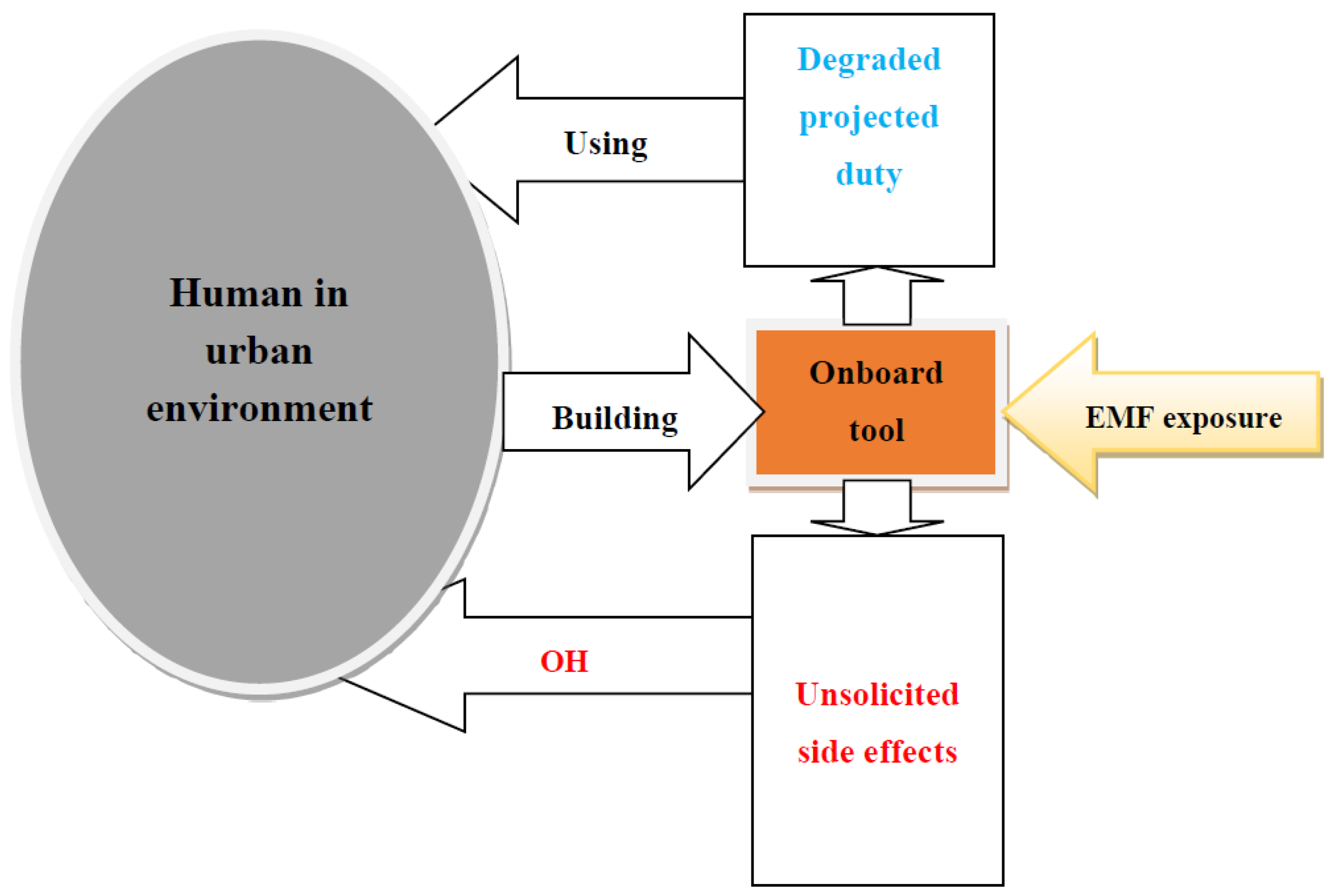
Figure 2.
RA and OH approaches involving the eco-design and use of onboard tool considering urban SC biodiversity via handling of adverse EMF effects [41].
Figure 2.
RA and OH approaches involving the eco-design and use of onboard tool considering urban SC biodiversity via handling of adverse EMF effects [41].
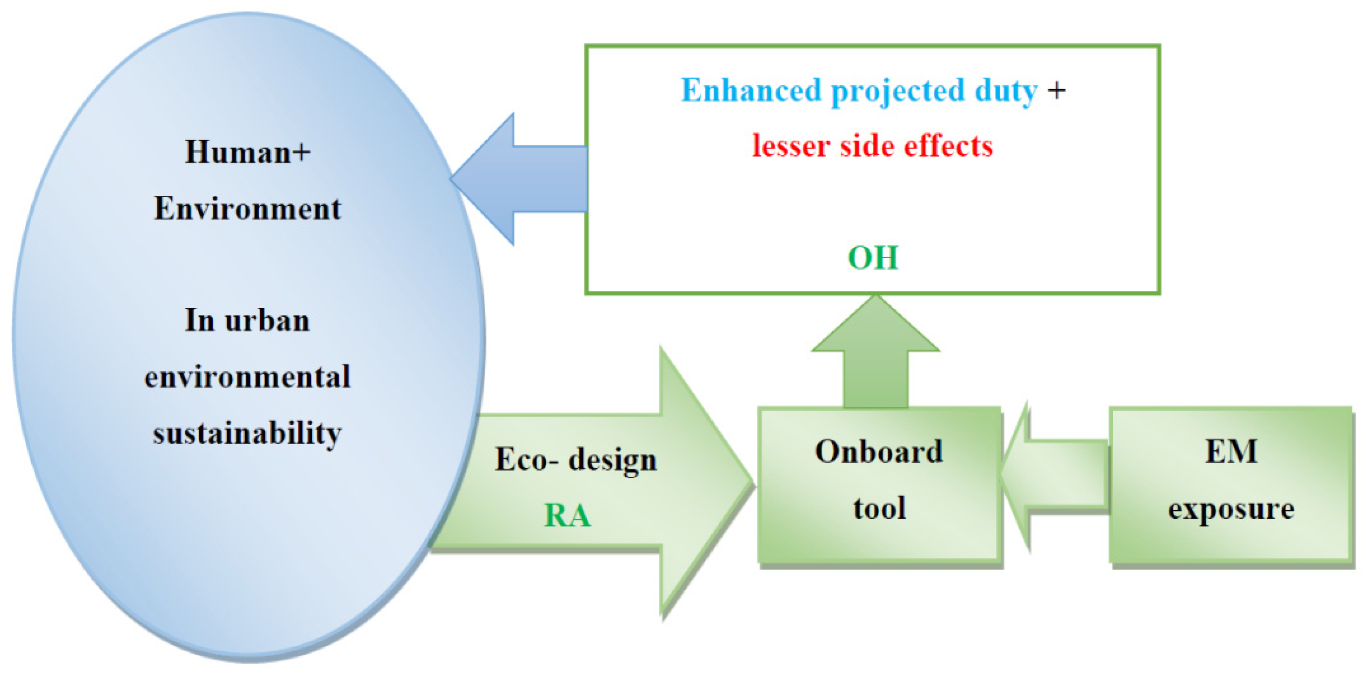
Figure 3.
MRI RF (at 63.87 MHz, B0 1.5 T) magnetic field (vertically directed) distribution in the case of no material [36].
Figure 3.
MRI RF (at 63.87 MHz, B0 1.5 T) magnetic field (vertically directed) distribution in the case of no material [36].
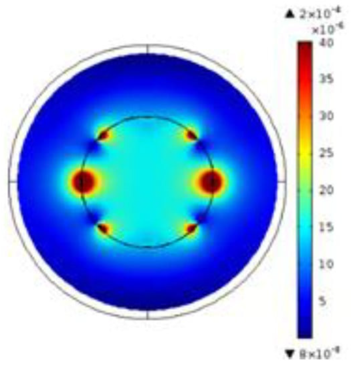
Figure 4.
MRI RF magnetic field distribution with the insertion of a piezoelectric coated by electrodes (a) material outline (b) field distribution with electrodes perpendicular to the field (c) field distribution with electrodes parallel to the field [36].
Figure 4.
MRI RF magnetic field distribution with the insertion of a piezoelectric coated by electrodes (a) material outline (b) field distribution with electrodes perpendicular to the field (c) field distribution with electrodes parallel to the field [36].
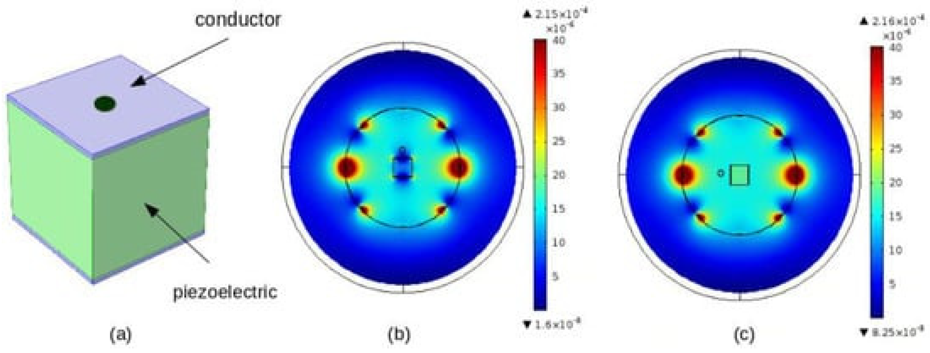
Figure 5.
Schematics of IPT involving ICT, (a) compensated ICT, (b) IPT components, (c) 3D Structure ICT including ground transmitter, EV bottom receiver coils, with their magnetic ferrites, and a steel chassis plate [42].
Figure 5.
Schematics of IPT involving ICT, (a) compensated ICT, (b) IPT components, (c) 3D Structure ICT including ground transmitter, EV bottom receiver coils, with their magnetic ferrites, and a steel chassis plate [42].
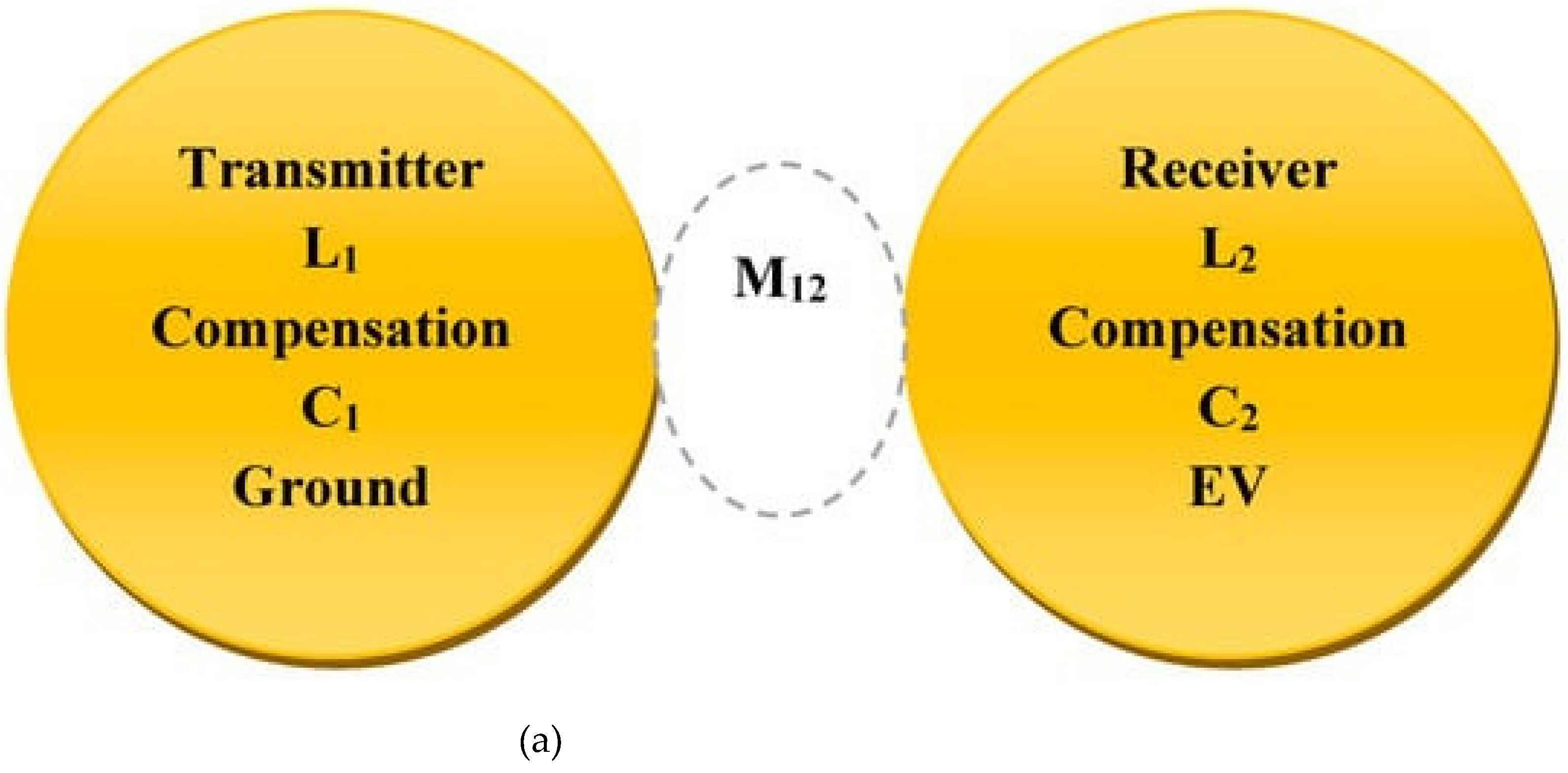
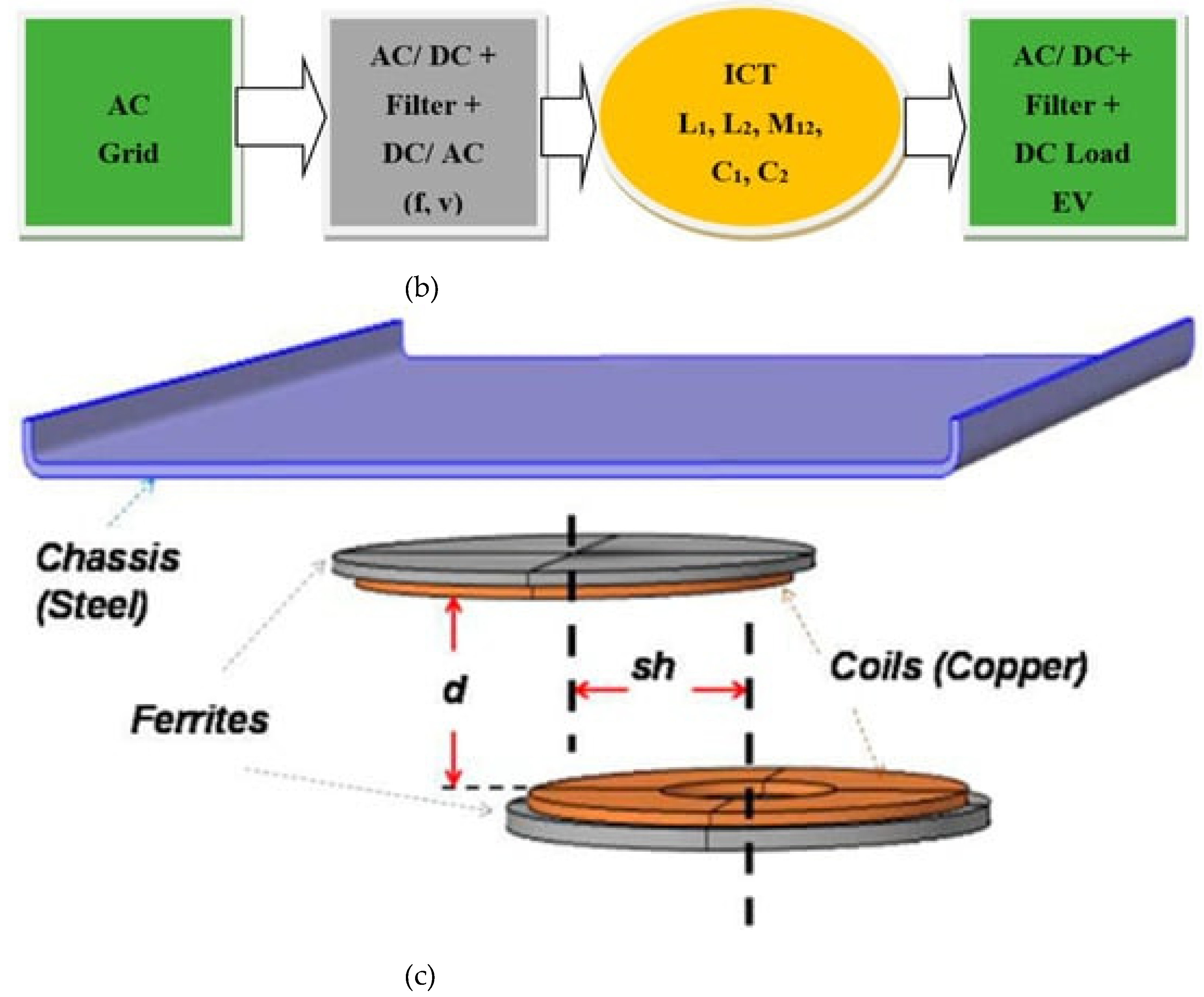
Figure 6.
Causal approach to design and energy spent in EV-IPT in relation to RA and OH approaches, (a) unsustainable design case, (b) sustainable design and use of clean energy case counting all SC biodiversity [42].
Figure 6.
Causal approach to design and energy spent in EV-IPT in relation to RA and OH approaches, (a) unsustainable design case, (b) sustainable design and use of clean energy case counting all SC biodiversity [42].
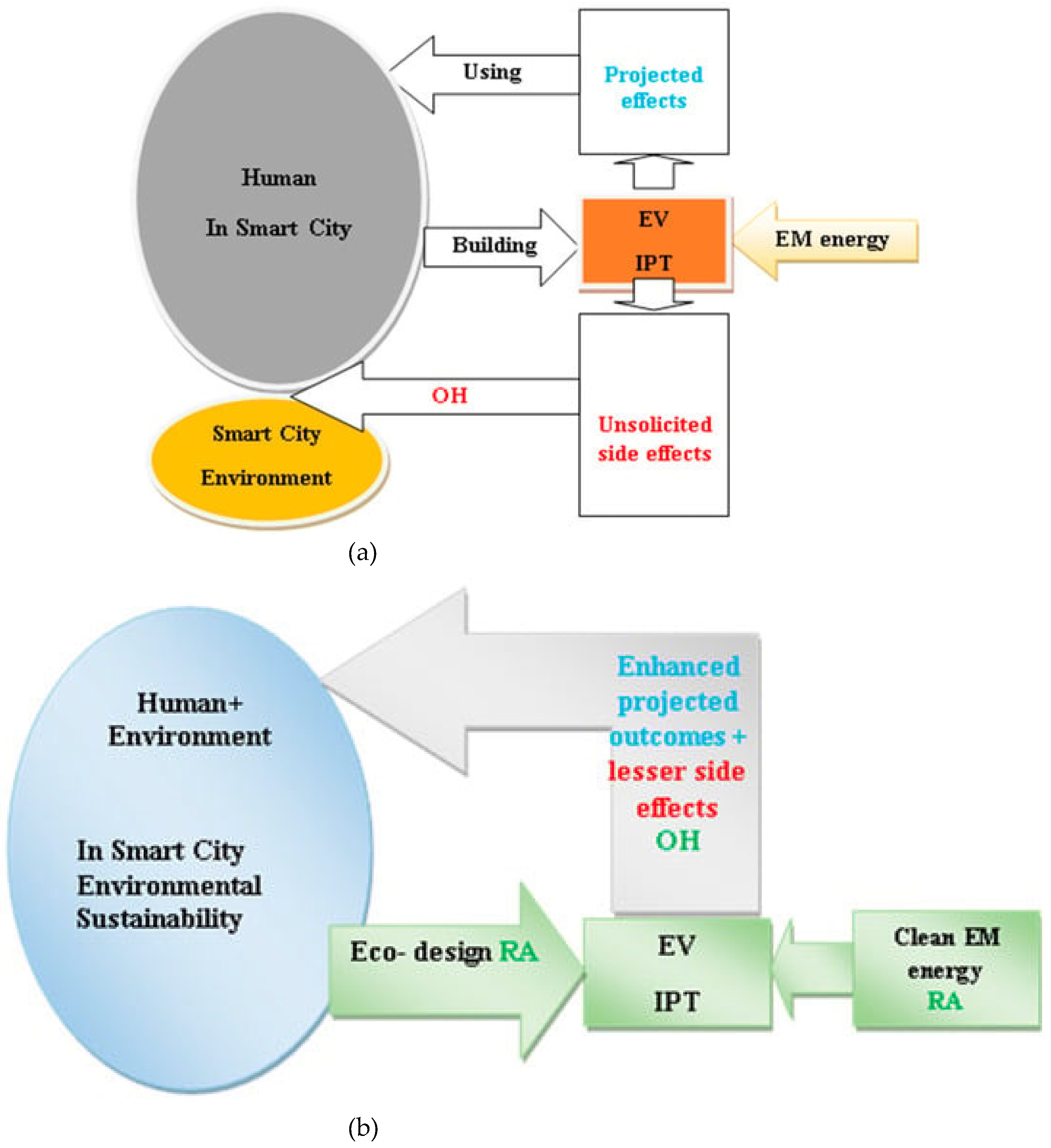
Figure 7.
High-resolution human body model with its different organs and tissues, [45].
Figure 7.
High-resolution human body model with its different organs and tissues, [45].
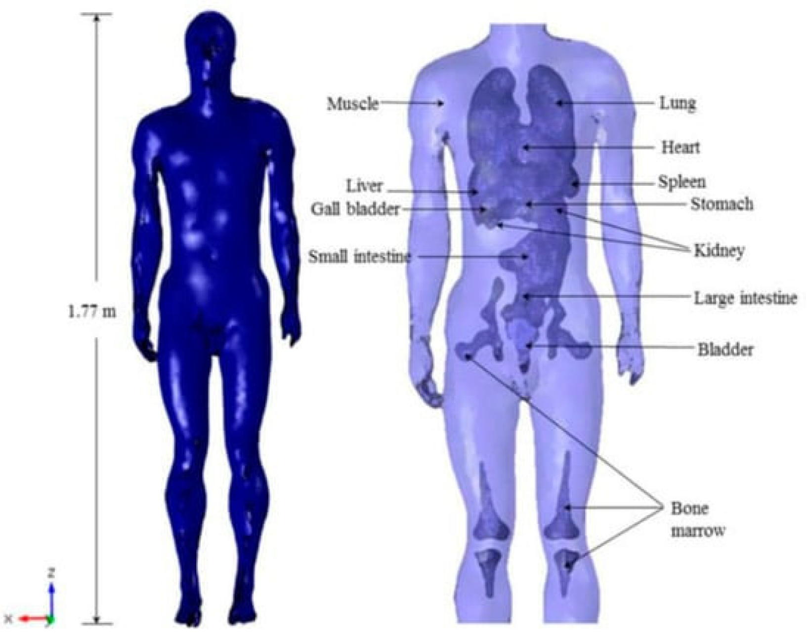
Figure 8.
Induced Figure 8. Field distribution in a body exposed to an ICT (3kW, 30 kHz) under an EV, for a horizontal ground placed body beside the EV. (a) Magnitude of B (T), (b) Magnitude of E (V/m), [45].
Figure 8.
Induced Figure 8. Field distribution in a body exposed to an ICT (3kW, 30 kHz) under an EV, for a horizontal ground placed body beside the EV. (a) Magnitude of B (T), (b) Magnitude of E (V/m), [45].
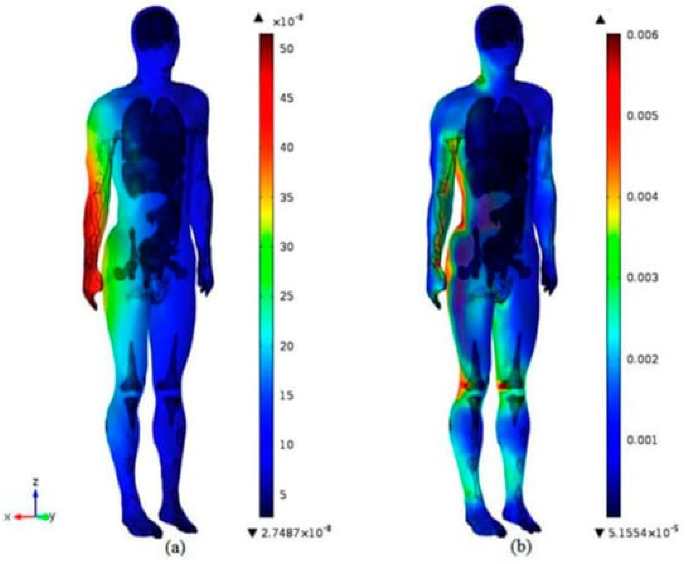
Figure 9.
Bus charging its batteries via an ICT on the roof during its end-of-tour stop without passengers.
Figure 9.
Bus charging its batteries via an ICT on the roof during its end-of-tour stop without passengers.
Disclaimer/Publisher’s Note: The statements, opinions and data contained in all publications are solely those of the individual author(s) and contributor(s) and not of MDPI and/or the editor(s). MDPI and/or the editor(s) disclaim responsibility for any injury to people or property resulting from any ideas, methods, instructions or products referred to in the content. |
© 2024 by the authors. Licensee MDPI, Basel, Switzerland. This article is an open access article distributed under the terms and conditions of the Creative Commons Attribution (CC BY) license (http://creativecommons.org/licenses/by/4.0/).
Copyright: This open access article is published under a Creative Commons CC BY 4.0 license, which permit the free download, distribution, and reuse, provided that the author and preprint are cited in any reuse.


