
Submitted:
22 November 2024
Posted:
22 November 2024
You are already at the latest version
Abstract
In order to address the challenges of high labour intensity, low efficiency and harsh working environment in Chinese duck egg collecting operations, this study proposes an optimization technique for egg-collecting robot path planning based on ROS (Robot Operating System). Firstly, the Gmapping algorithm is used to map the laboratory environment for navigation purposes, while the AMCL (Adaptive Monte Carlo Localization) method is used to obtain the pose information of the egg-collecting robot. Secondly,the sequence of egg collecting tasks is determined using the ACA (Ant Colony Algorithm) to compute the shortest path length and node order. Finally, the navigation target points for egg collecting are computed to obtain their world coordinate positions. The global path planning for egg collecting is performed using the Dijkstra algorithm, and the local path planning and obstacle avoidance for the robot is implemented using the DWA (Dynamic Window Approach) algorithm. A test platform was set up based on the actual working environment of the egg-collecting robot to conduct continuous egg collecting navigation experiments, and the final egg collecting navigation accuracy rate was 89.3%.
Keywords:
egg-collecting
; ROS
; path planning
; DWA algorithm
1. Introduction
Eggs are a nutritionally dense food ingredient that offers a palatable and cost-effective dietary option for the Chinese population. Furthermore, eggs represent a promising raw material for a multitude of industries, with a promising industrial outlook. China is the world's foremost producer and consumer of poultry eggs, accounting for 42% of the global total. In 2023, China had a total of 149 million ducks in egg production, with an egg output of 2.67 million tonnes and a total output value of 37.7 billion yuan [1,2,3]. In the egg production industry, egg collection represents a crucial aspect of daily management. However, traditional inspection and egg collection methods rely on manual operation, which is labour-intensive and inefficient. Additionally, the breeding environment within the duck house is characterised by the presence of pathogens, including Campylobacter, Aspergillus sydowii, Penicillium, and others [4,5]. Prolonged exposure to such an environment has been identified as a significant risk factor for adverse physical and mental health outcomes [6]. It is therefore of great importance to develop a robot that is capable of automatically performing the egg-collecting task in order to improve the automation level and production efficiency of poultry egg production. The path planning optimisation technology is the core technology that enables the egg collection robot to navigate, identify and locate eggs in the complex environment of the poultry house, and plan the optimal egg-collecting path to accurately and efficiently reach each egg-collecting point.
At the present time, research into the planning of routes for the collection of eggs is concentrated in developed countries. As early as 2017, researchers at the Georgia Tech Research Institute developed a mechanical system, designated the Grow-out House Robot (Gohbot), for automated egg collection. Following 83 tests, the system demonstrated a success rate of 91.6% [7,8]. In 2018, researchers at Wageningen University developed PoultryBot, an autonomous mobile robot that collect eggs through a mechanism in the form of a rolling grid. The robot was tested on 313 eggs, with 46% being successfully collected, 37% being unsuccessful, and 16% being missing. These results effectively validated the effectiveness and feasibility of the concept of the egg collection device [9,10]. Furthermore, a NURAC (Non-uniform Repeated Area Coverage) area path planning algorithm based on DP (Dynamic Programming) was introduced, with the distribution probability of the floor eggs evaluated in order to enhance the adaptability and flexibility of the mobile egg-collecting robot in diverse farming environments [11,12].
The research on egg-collecting path-planning technology in China commenced relatively recently, with the majority of studies focusing on assembly line egg collection. There has been comparatively little research conducted on the development of mobile egg-collecting robot platforms. Following recent developments, China has made notable progress in the field of egg collection robotics, with the creation of an array of specialized machines [13,14]. These studies have significantly advanced the development of mobile egg collection robots, thereby accelerating the process of agricultural automation and intelligence. Nevertheless, the financial outlay required for the current research is considerable, and it remains at the pilot research stage. This paper presents a methodology for optimising the path planning of a mobile egg-collecting robot based on ROS. The research content includes the configuration of a robot cost map, the analysis of robot pose information and the formulation of an egg-collecting sequence. A test platform was constructed to imitate the actual working environment of the egg-collecting robot, and a navigation test of continuous egg-collecting was conducted.
2. Materials and Methods
2.1. Design of Egg-Collecting Device
This paper presents a wheeled mobile robot that serves as the foundational chassis, incorporating a variety of multifaceted components, including a robotic arm, an egg basket, a LiDAR sensor, and a depth camera. The robotic arm guarantees the smooth and uninterrupted movement of each joint during complex operations, thereby preventing any hindrance or obstruction. The egg basket is situated in a strategic position within the robotic arm's reach, thereby facilitating efficient egg collecting and storage. The LiDAR sensor ensures that occlusion is avoided while enabling precise positioning, environmental mapping and dynamic obstacle detection. Moreover, the depth camera provides an extensive field of view, facilitating the identification and positioning of duck eggs with greater ease. In light of the aforementioned considerations, the structural configuration of the robot is depicted in Figure 1:
2.2. Map Modeling and Robot Positioning
2.2.1. SLAM Map Modeling
In order to plan the trajectory of the egg-collecting robot within the cost map, a static map is initially generated in accordance with the specific work site. Simultaneous Localization and Mapping (SLAM) is a technology that enables the estimation and localization of poses in unknown environments. It is a widely utilized technique in the field of mobile robotics, unmanned driving and construction [15,16,17]. In consideration of the operational context of the robot and its intrinsic hardware capabilities, the Gmapping algorithm was selected for the generation of navigation maps within the laboratory environment. The egg-collecting robot employs a multi-sensor fusion of vision, lidar, and IMU (inertial measurement unit) inertial elements to scan and construct a representation of the scene environment through the use of SLAM [18], as illustrated in Figure 2a. The map generated by the robot is stored in portable grayscale map (.pgm) format, as illustrated in Figure 2b.
Once the configuration has been completed, the robot cost map can be generated, as illustrated in Figure 3. This demonstrates the impact of incorporating different maps into the RVIZ interface. Figure 3d serves as a case in point, wherein the purple area denotes the obstacle, the light blue area represents the inscribed area, the blue area signifies the restricted area, and the gray-white area corresponds to the free area. In the navigation process, the robot chassis is regarded as a particle point, and it is inevitable that the robot will collide with obstacles when it is in the fatal area and the inscribed area. The probability of a robot colliding in the restricted area is contingent upon its attitude. While the restricted area is technically passable, under normal circumstances, robots are inclined to avoid it. The free zone, conversely, represents the primary traffic area for robots, wherein collisions are unlikely to occur.
2.2.2. AMCL Positioning Method
The AMCL algorithm is a particle filter algorithm, the principal concept of which is to simulate the pose of N random particles in relation to the robot, calculate their respective weights, and determine the credibility of the pose information contained in the particles through the particle weight value, with the objective of completing the prediction of the robot's pose [19,20]. In order to facilitate the mapping and navigation processes, it is necessary for the egg-collecting robot to obtain its own position and posture on a continuous basis. In this context, the AMCL method is employed for the purpose of locating the robot.
The AMCL node employs map data and LiDAR information as inputs to establish the transformation function (TF) of the robot's chassis coordinate system in real-time. Furthermore, the TF transformation relationship between the odometer coordinate system and the map coordinate system is acquired, along with the robot's pose information and predicted particle point cloud data. As a result of these processes, the AMCL node is able to achieve real-time positioning of the robot.
2.3. Egg Collecting Path Planning
The global planning process of the egg-collecting path is divided into four stages. Firstly, the egg-collecting sequence is formulated. Secondly, the navigation target point is calculated. Thirdly, global path planning is conducted. Finally, local path planning and obstacle avoidance are performed.
2.3.1. Establishment of Egg Collecting Sequence
The ACA is utilised to address the challenge of determining the optimal egg-collecting order. The initialisation phase of the algorithm involves the setting of various parameters, including the specified number of ants (denoted by the parameter ), the pheromone constant (denoted by ), the maximum iteration count (denoted by ), and the pheromone factor. Subsequently, each ant's starting point is randomly assigned. The roulette method is then employed to select the subsequent target point for each ant. Upon transitioning to a new node, the previously traversed node is added to a taboo table, ensuring that the ant does not revisit this point during the iteration process. The probability formula for ant moving from node to node is illustrated in Figure 1 below.
In the formula, represents the pheromone concentration of nodes to at time . is the heuristic function, which is the reciprocal of the distance between nodes and . The and the represent the pheromone importance factor and the heuristic function importance factor, respectively. In this paper, the ant cycle model is adopted, and the path length of each ant in the process of each iteration is calculated after each iteration. Subsequently, the pheromone update is carried out, and the pheromone update formula 2 is presented in the following section.
In the aforementioned equation, represents the pheromone volatile factor, denotes the pheromone content released by ant on the path between nodes and , and the formula for is illustrated in Equation 3:
In the aforementioned equation, represents the pheromone constant, which is provided upon the initialisation of the parameter. denotes the total length of the path traversed by ant within the specified iteration. In this context, and represent the path between nodes and and the set of paths taken by ant in the current iteration. Once the pheromone update is complete, the process will resume with the iterative operation until the maximum number of iterations has been reached. The shortest path and the node order will be the final outputs. The shortest path is defined as the shortest distance or optimal path found by the egg-collecting robot from the starting point to the end point in a specific environment. The robot must move to the location of the duck egg in the most efficient way and return to the starting point or continue to the next task.
2.3.2. Egg Collecting Navigation Target Point Calculation and Global Path Planning
In light of the increasingly complex and dynamic nature of modern work environments, the development of effective global path planning algorithms has become a pivotal research area. These algorithms aim to enhance the real-time obstacle avoidance, path smoothness, and overall planning efficacy of robotic systems through the optimization and refinement of underlying algorithms [21]. Figure 4a depicts the operational envelope of the robotic arm. In accordance with the robot chassis coordinate system , the optimal position of the duck egg is situated at a distance of 15cm from the head of the trolley along the central axis of the trolley. The coordinates of the duck egg relative to the robot chassis coordinate system are represented by . A pose geometric model is formulated based on the world coordinate system, as illustrated in Figure 4b.
If the robot is currently situated at coordinate within the world coordinate system, and a duck egg is identified at point , the egg-collecting navigation target is constituted by a position coordinate and an attitude angle. Let point represent the location of the egg-collecting target. In order to successfully collect the egg, the robot must navigate to point and adjust its attitude angle to . Given that point and point are separated by a distance , and point lies on the direct line connecting the robot's current position to the duck egg's location, the following constraint equations can be formulated:
In light of the fact that the duck egg-collecting robot does not necessitate an excessively high planning speed, this paper deploys the breadth-first Dijkstra algorithm with a view to ensuring the global optimality of the path.
2.3.3. Local Path Planning and Obstacle Avoidance
In this paper, the DWA is employed for the purposes of local path planning and obstacle avoidance in the context of a four-wheeled mobile robot. Firstly, the robot motion model is analysed, and the kinematic model of the four-wheeled mobile robot is presented in Figure 5.
In considering the motion of an Ackermann steering trolley over an adjacent time interval, it is only necessary to take into account the linear velocity along the -axis of the chassis coordinate system and the angular velocity of rotation around the -axis. Given the relatively short distance traversed during this interval, the motion trajectory of the trolley can be approximated as a straight line. As illustrated in Figure 6, at a specific point in time, the position coordinates of the robot in the world coordinate system are represented by , and the heading angle of the trolley is also indicated by . Additionally, the displacement of the trolley over the time interval can be approximated as . Based on these considerations, the displacement of the robot in the world coordinate system during this time period can be mathematically expressed as follows:
The configuration of the robot in the global coordinate system at the subsequent instant is as follows:
In accordance with the kinematic model and the prevailing velocity of the robot, the trajectory that it will pursue can be calculated. The DWA algorithm, as employed in this paper, determines the linear velocity and angular velocity that the robot is capable of attaining at the subsequent moment, taking into account its current velocity state and the hardware limitations that it is operating within. The algorithm performs discrete sampling with a specified resolution within the ranges of these two possible velocities. The set of sampling values for the linear velocity is given by Equation (7), and the set of sampling values for the angular velocity is similarly defined. The Cartesian product of these two sets of sampling values is computed as shown in Equation (8):
In the aforementioned context, represents the set of potential motion states that the robot is capable of achieving in the subsequent moment. Based on the aforementioned motion states, the robot's trajectory for the subsequent time period is predicted using a variety of combinations of linear and angular velocities. Each velocity combination is associated with a distinct predicted trajectory. Subsequently, the generated trajectories are evaluated according to three criteria: the heading evaluation function , the safety evaluation function , and the speed evaluation function . With regard to the heading evaluation function , represents the declination angle between the end direction of the trajectory and the target direction predicted by the velocity combination . The safety evaluation function represents the distance between the end of the trajectory and the nearest obstacle. The velocity evaluation function represents the linear velocity corresponding to the trajectory. Given the considerable disparity in the numerical values among the three evaluation functions, it is essential to normalise these functions to prevent any one of them from unduly influencing the final result. The method for calculating the normalised index value entails dividing the original index value by the sum of the index values for all prediction trajectories, as illustrated in Equation (9):
The final evaluation function is the weighted sum of the aforementioned three evaluation functions, as illustrated in Equation (10). The DWA algorithm assesses each predicted trajectory individually using the aforementioned evaluation function, identifies the optimal trajectory, and transmits the corresponding velocity data to the chassis controller.
In the formula, the variables , , and represent the weight values assigned to the heading evaluation function, the safety evaluation function, and the speed evaluation function, respectively. The aforementioned weights exert a direct influence on the robot's path selection. In this paper, the weight of the velocity evaluation function is employed as a reference point to examine the impact of the weights assigned to the heading and safety evaluation functions on the path planning process on the MATLAB platform. In order to construct an obstacle map based on the actual operational environment of the robot, the values of , , and were initially set to 0.05, 0.075, and 0.1, respectively. During the experimental phase, and were varied with five and three different contrast values, respectively, while the value of was maintained at a constant level. These adjustments were made to and , respectively, according to a specific step size. The trajectory simulation time was conducted for a duration of three seconds. The results of the DWA trajectory planning simulation experiment are presented in Figure 6.
The aforementioned experiments yield the following conclusions: Should the value of be excessively small, the robot's capacity to rapidly modify its trajectory will be significantly diminished, potentially impeding its ability to reach the intended point of arrival in a smooth and efficient manner. As the value of increases, the robot becomes more inclined to select a path with minimal angular deviation from the target direction, thereby reducing the path length to a certain extent. However, if the value of is excessive, the robot may become trapped in a local optimal path, resulting in an increase in path length. Conversely, as the value of increases, the robot is more likely to select a path that maintains a greater distance from obstacles. However, when the value of is too low, there is an increased risk of collision. Conversely, if the value of is excessively high, it may prompt the robot to exhibit excessive avoidance behaviour, ultimately increasing the path length.
In addition to the weight parameters, the trajectory prediction time also has a significant impact on path planning, and thus requires further investigation. To investigate this, a comparison experiment was conducted using the aforementioned set of parameters. Six comparison values were selected from 1.5 seconds to 4 seconds, with an increment of 0.5 seconds. The trajectory prediction time and path length were, respectively, carried out for trajectory planning simulation experiments, as illustrated in Figure 7.
The aforementioned experimental results demonstrate that setting the prediction time too short can impede the robot's capacity to timely avoid obstacles during its journey, which may ultimately result in collisions. Conversely, setting the prediction time too long may prompt the robot to exhibit excessive avoidance behaviour, which could ultimately result in it missing the optimal path.
The cutting methods employed by existing vegetable grafting machines can be broadly classified into two categories: flat cutting methods and oblique cutting methods. In accordance with the technical specifications of the full-tray grafting machine under investigation, the cutting apparatus has been designed to utilise the oblique cutting method. The optimal cutting angle was ascertained through experimentation.
3. Results
3.1. Test Method
The duck egg-collecting robot is situated at the initial point of the navigation map, with five duck eggs randomly positioned within its effective detection range. Upon completion of the duck egg positioning, a calculated navigation target list is transmitted to the navigation node. Subsequently, the robot is directed to each navigation target point in sequence. If the duck eggs are located within the operational range of the mechanical arm upon reaching the designated navigation point, the navigation is deemed successful. Otherwise, it is considered unsuccessful, as illustrated in Figure 8. To ensure the reliability of the test results, 30 repeated tests were conducted, and the accuracy of the navigation was recorded five times in each test.
3.2. Test Equipment and Materials
Duck egg collecting robot prototype (including Intel Realsense D435i depth camera, LiDAR, IMU and other sensors), duck eggs, litter, tape measure.
3.3. Test Results and Analysis
Given the considerable number of trials conducted, this paper focuses on documenting the samples of experiments that resulted in navigation failures. Table 1 presents the test results, wherein "T" denotes successful navigation and "F" signifies unsuccessful navigation.
As illustrated in Table 1, samples 8, 17, and 29 exhibited a series of consecutive navigation failures. The underlying causes of these failures in the duck egg-collecting robot can be attributed to a number of factors, including significant motion control errors within the robot itself, visual positioning errors of the duck eggs, and positioning errors of the robot. The robot determines the optimal position for egg collecting by integrating its current location with the target duck egg's position. It is noteworthy that navigation failures resulting from excessive visual positioning errors of the duck eggs do not impede subsequent navigation attempts. However, navigation failures resulting from the robot's own positioning errors impede the acquisition of accurate current position information, leading to substantial deviations in the calculation of the egg-collecting position and posture point. This, in turn, elevates the likelihood of subsequent navigation failures. In the aforementioned experiments, 30 sets of repeated trials were conducted, amounting to a total of 150 navigation attempts. Of these, 16 navigation failures were recorded, resulting in an overall navigation accuracy rate of 89.3%.
4. Conclusions
In order to address the issues of high labour intensity, low efficiency and poor working environment associated with manual egg collection in the egg breeding industry, this paper proposes the use of a fusion ACA, Dijkstra algorithm and DWA algorithm for egg collecting robot based on ROS. The efficacy of the proposed strategy and the viability of the proposed collecting method are validated through experimentation. The following specific conclusions may be drawn:
- (1)
- This paper employs the Gmapping algorithm for the purpose of creating a map of the laboratory environment and generating a cost map for the robot. The AMCL method is utilised for the purpose of locating the egg-collecting robot and obtaining its pose information. To address the issue of the optimal sequence for collecting eggs, the ACA is implemented, resulting in the determination of the shortest path length and the optimal order of egg-collecting nodes. The target point for egg-collecting navigation is calculated in order to ascertain its world coordinate position. Subsequently, the Dijkstra algorithm is employed for global path planning for egg collecting, while the DWA algorithm is used for local path planning and obstacle avoidance of the robot. Simulation experiments were conducted on the Matlab platform to identify optimal parameter combinations for the DWA algorithm. The results indicated that a heading evaluation function weight of 0.05, a safety evaluation function weight of 0.1, and a speed evaluation function weight of 0.1 were the optimal parameter combinations;
- (2)
- A test platform was constructed in the laboratory to emulate the operational context of the egg-collecting robot. The robot's continuous egg-collecting navigation performance was evaluated through a series of tests, yielding an accuracy rate of 89.3%.
Author Contributions
Conceptualization, W.L., R.C., and Y.S.; methodology, W.L. , R.C., and D.G.; formal analysis, R.C., D.G., and X.F.; investigation, Y.S. and X.F.; drawings, Y.S. and X.F.; writing—original draft preparation, W.L. and R.C.; writing—review and editing, D.G.; supervision, W.L.; project administration, W.L. and D.G.; funding acquisition, W.L.. All authors have read and agreed to the published version of the manuscript.
Funding
This research was supported by the Fundamental Research Funds for the Central Universities (Grant No.2662022GXYJ004).
Institutional Review Board Statement
Not applicable.
Informed Consent Statement
Not applicable.
Data Availability Statement
The data presented in this study are available on request from the corresponding author.
Acknowledgments
This work was supported by Weiguo Lin and Hao Yang.
Conflicts of Interest
The authors declare no conflicts of interest. The funders had no role in the design of the study; in the collection, analyses, or interpretation of data; in the writing of the manuscript; or in the decision to publish the results.
References
- Hou, S.S.; Liu, L.Z. 2023 Waterfowl Industry and Technology Development Report. Chinese Journal of Animal Husbandry 2024, 60, 318–321. [Google Scholar]
- Liang, W.; Song, J.S.; Bao, E.C.; Lin, Y.; Guo, B.B.; Ying, S.J.; Wu, Z.X. Waterfowl (duck) breeding mode and development trend based on environmental control. Journal of Animal Ecology 2024, 45, 92–96. [Google Scholar]
- Liu, L.Z. Research and judgment on the current situation and future trend of China's laying duck industry market. China Poultry Industry Guide 2024, 41, 13–22. [Google Scholar]
- Iulia, A.B.; Igori, B.; Ioan, P.; Lavinia, S.; Cosmin, A.P.; David, M.C.; Joanne, L.; Todd, C.; Alastair, D.; Nicolae, C. Mechanistic concepts involved in biofilm associated processes of Campylobacter jejuni: persistence and inhibition in poultry environments. Poult. Sci. 2024, 103, 104328. [Google Scholar]
- Wang, X.L.; Chen, L.; Yang, G.W.; Cai, Y.M.; Yu, G.L. Bacterial and fungal aerosols in poultry houses: PM2.5 metagenomics via single-molecule real-time sequencing. Poult. Sci. 2024, 103, 104348. [Google Scholar] [CrossRef] [PubMed]
- Huan, L.H. The main problems and countermeasures in the management of layer breeding. Jilin Animal Husbandry and Veterinary Medicine 2023, 44, 84–85. [Google Scholar]
- Colin, T.U.; Wayne, D.D.; Benjamin, J.; Aneri, M. Robotics for Poultry House Management. 2017 ASABE Annual International Meeting, Paper No. 1701103, 1-8, Washington, 2017. [CrossRef]
- Benjamin, J.; Colin, U. Autonomous robotic system for picking up floor eggs in poultry houses. 2017 ASABE Annual International Meeting, Paper No. 1700397, 1-5, Washington, 2017. [CrossRef]
- Bastiaan, A.V.; Sam, K.B.; Joris, M.M.I.; Eldert, J.V. Evaluation of the performance of PoultryBot, an autonomous mobile robotic platform for poultry housess. Biosyst. Eng. 2018, 174, 295–315. [Google Scholar]
- Bastiaan, A.V.; Steven, V.H.; Joris, M.M.I.; Eldert, J.V. Object discrimination in poultry housing using spectral reflectivity. Biosyst. Eng. 2018, 167, 99–113. [Google Scholar]
- Bastiaan, A.V.; Joris, M.M.I.; Eldert, J.V. Probabilistic localisation in repetitive environments: Estimating a robot's position in an aviary poultry house. Computers and Electronics in Agriculture 2016, 124, 303–317. [Google Scholar]
- Bastiaan, A.V.; Gerard, L.V.W.; Peter, W.G.G.; Eldert, J.V.H. Path planning for the autonomous collection of eggs on floors. Biosyst. Eng. 2014, 121, 186–199. [Google Scholar]
- Ge, Y.J. Research on key technologies of intelligent collection trolleys for goose eggs. Yangzhou University, Yangzhou, China, 2023. [Google Scholar]
- Zhou, H.J. The design of a duck egg picking robot in flat mode. Huazhong Agricultural University, Wuhan, China, 2023. [Google Scholar]
- Sheng, X.D.; Mao, S.J.; Yan, Y.C.; Yang, X.K. Review on SLAM algorithms for Augmented Reality. Displays 2024, 84, 102806. [Google Scholar] [CrossRef]
- Li, L.; Lothar, S.; Kunal, K. Promising SLAM Methods for Automated Guided Vehicles and Autonomous Mobile Robots. Procedia Comput. Sci. 2024, 232, 2867–2874. [Google Scholar] [CrossRef]
- Andrew, Y.; Yong, K.C. Review of simultaneous localization and mapping (SLAM) for construction robotics applications. Automation in Construction 2024, 162, 105344. [Google Scholar]
- Wang, L.L.; Li, S.H.; Du, M.M.; Ji, G.L.; Li, K.S.; Liu, D. Terrain preview detection system based on loosely coupled and tightly coupled fusion with lidar and IMU. Measurement 2025, 242, 115924. [Google Scholar] [CrossRef]
- Tian, C.J.; Liu, H.B.; Liu, Z.; Li, H.Y.; Wang, Y.Y. Research on Multi-Sensor Fusion SLAM Algorithm Based on Improved Gmapping. IEEE Access 2023, 11, 13690–13703. [Google Scholar] [CrossRef]
- Cao, F.P.; Fan, Q.Y. Research on real-time positioning based on adaptive Monte Carlo algorithm. Comput. Eng. 2018, 44, 28–32. [Google Scholar]
- Zhao, S.W.; Shi, L.; Zhang, W.Z.; Deng, Z.H. Global dynamic path-planning algorithm in gravity-aided inertial navigation system. IET Signal Process. 2021, 15, 510–520. [Google Scholar] [CrossRef]
Figure 1.
Diagram of the 3D model: 1. Drive wheels; 2. Drive motors; 3. Egg basket; 4. LiDAR sensor; 5. Depth camera; 6. Alpha robotic arm; 7. End-of-arm camera; 8. Pneumatic suction cups; 9. Steering wheels; 10. Servos .
Figure 1.
Diagram of the 3D model: 1. Drive wheels; 2. Drive motors; 3. Egg basket; 4. LiDAR sensor; 5. Depth camera; 6. Alpha robotic arm; 7. End-of-arm camera; 8. Pneumatic suction cups; 9. Steering wheels; 10. Servos .
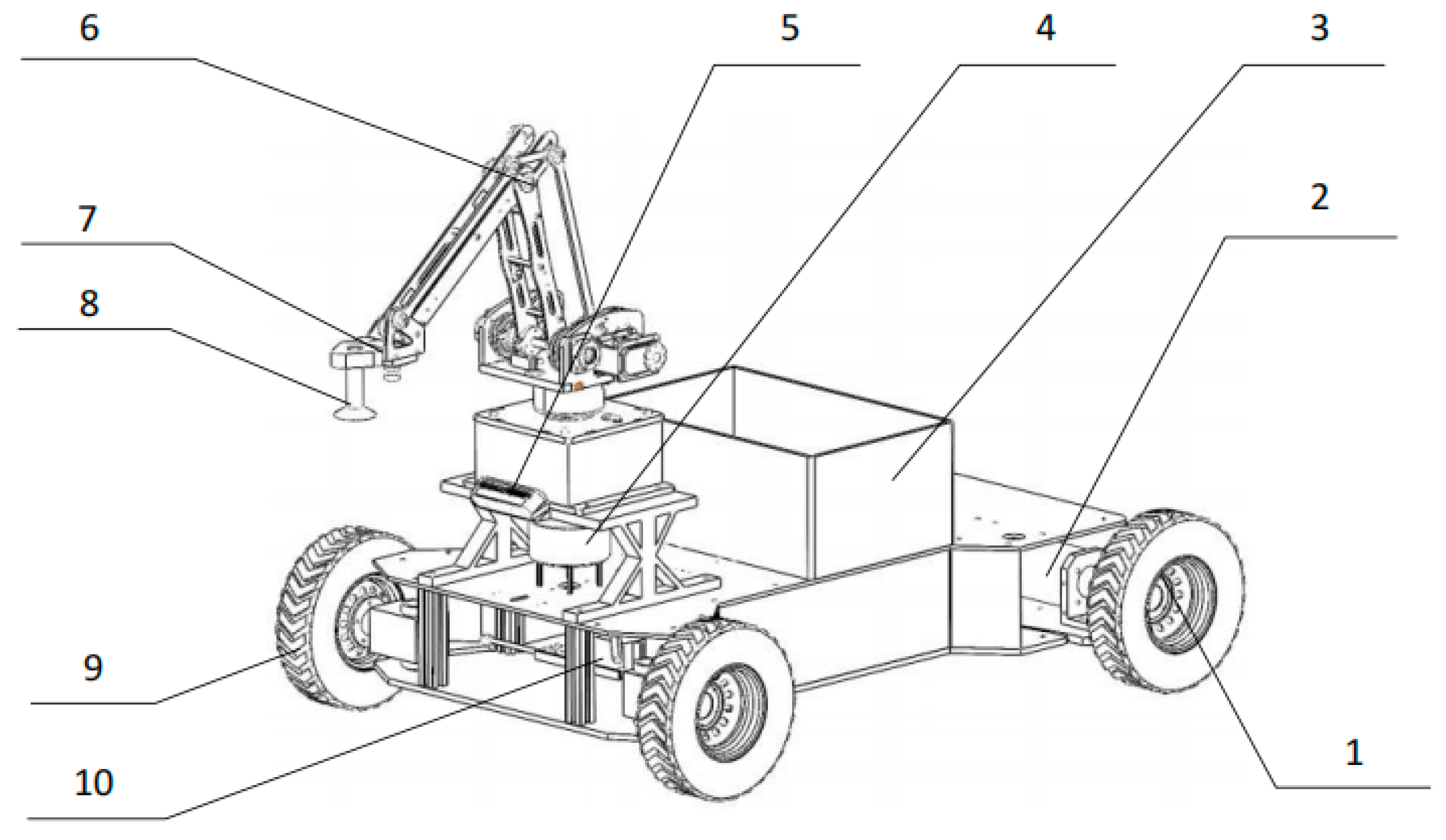
Figure 2.
Gmapping experiments.
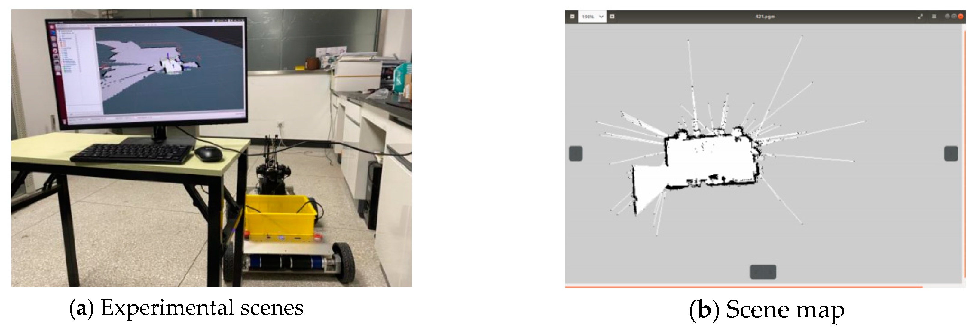
Figure 3.
Added effects to different maps.
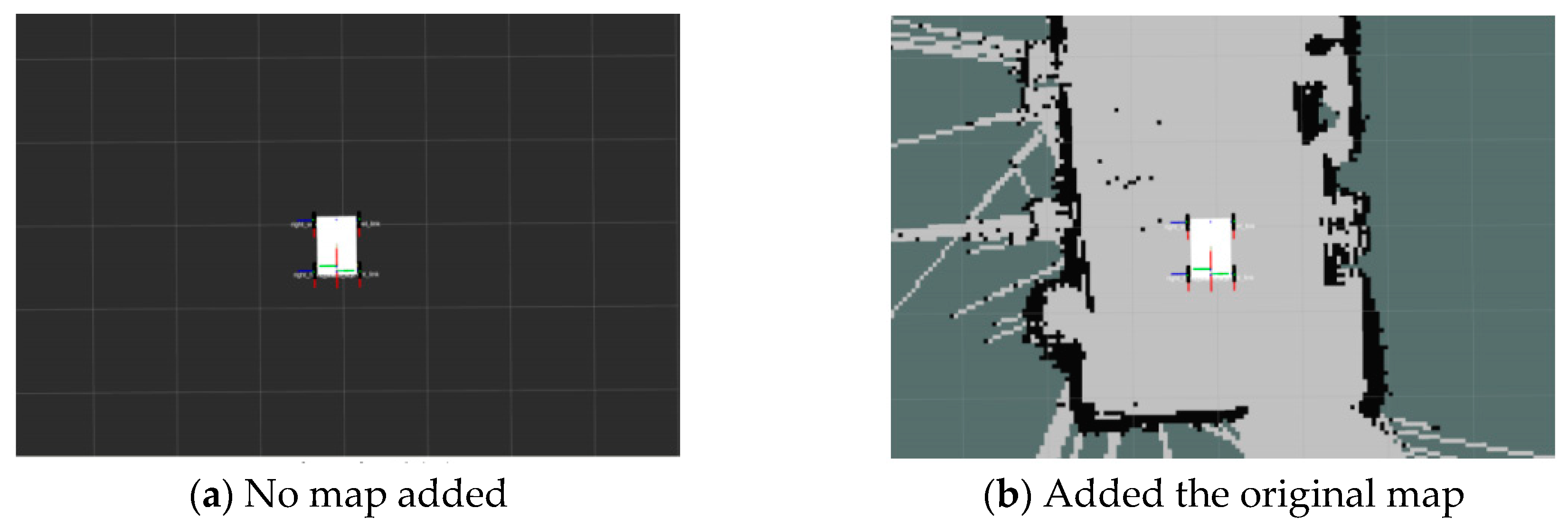
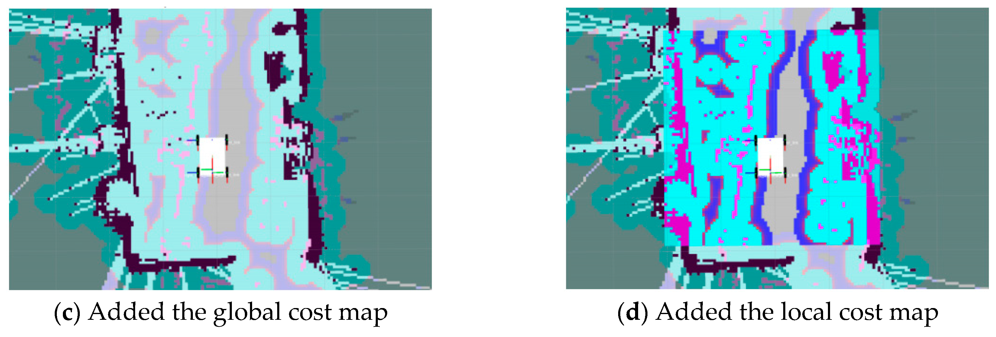
Figure 4.
Schematic diagram of the robot working.
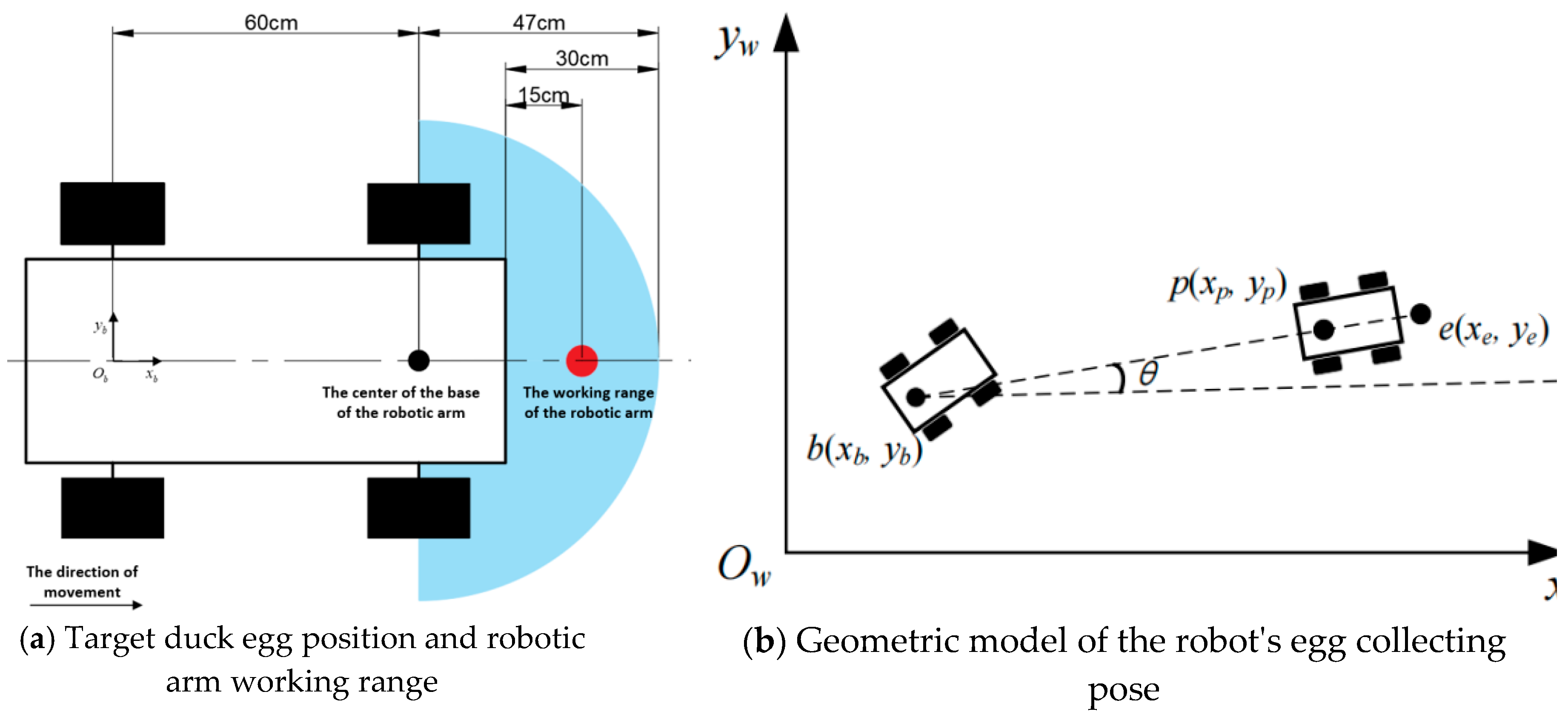
Figure 5.
Robot motion model.
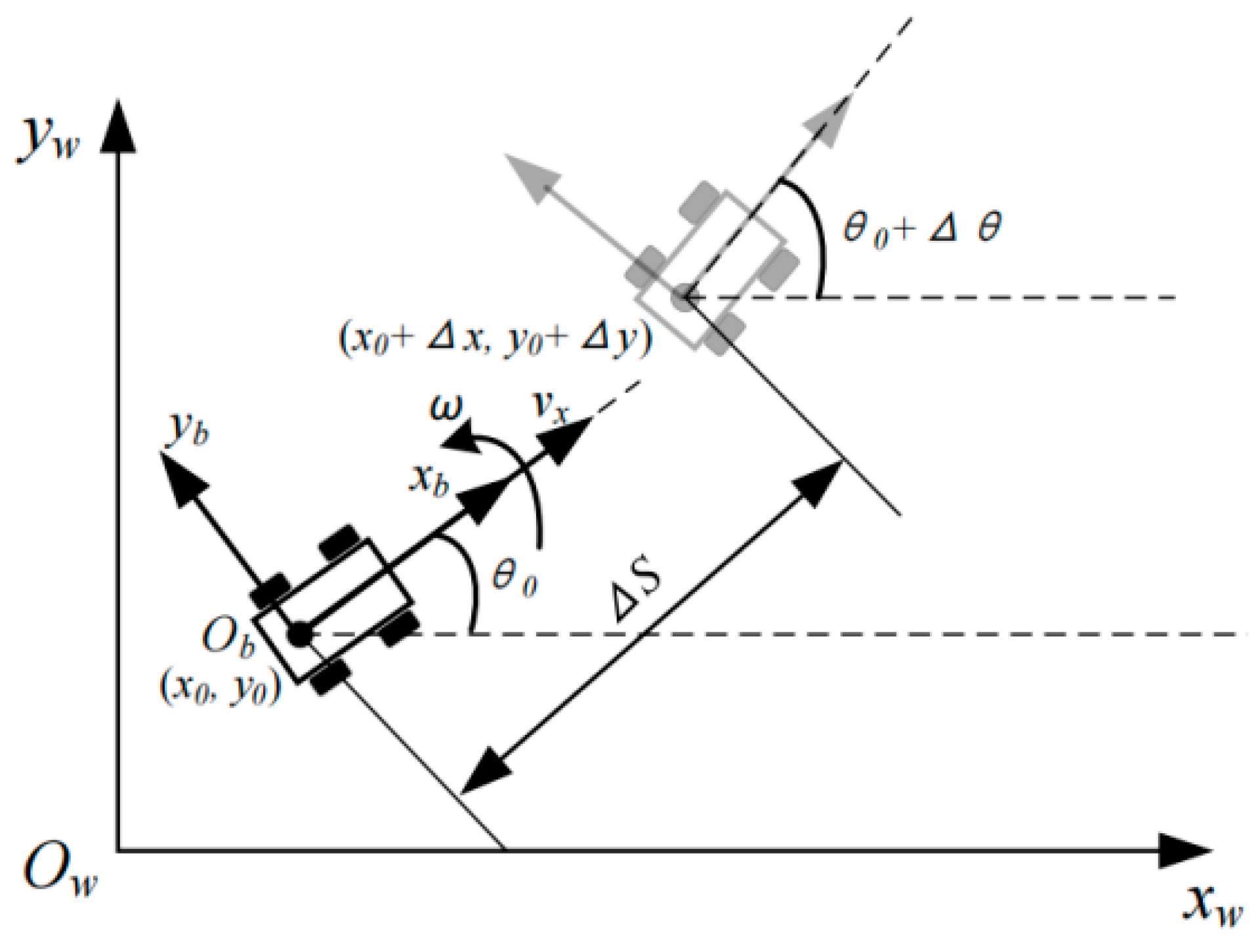
Figure 6.
DWA weight parameter simulation experiment results.
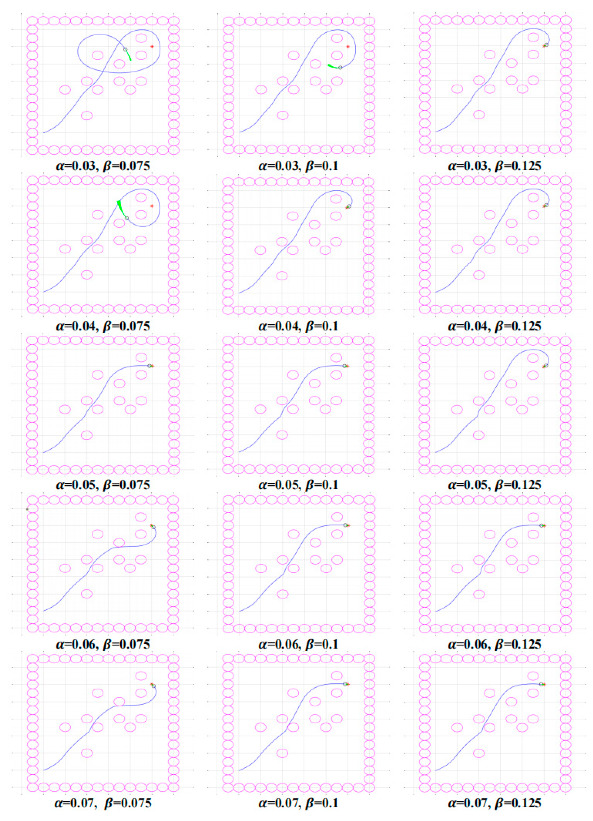
Figure 7.
DWA prediction duration simulation experiment results.
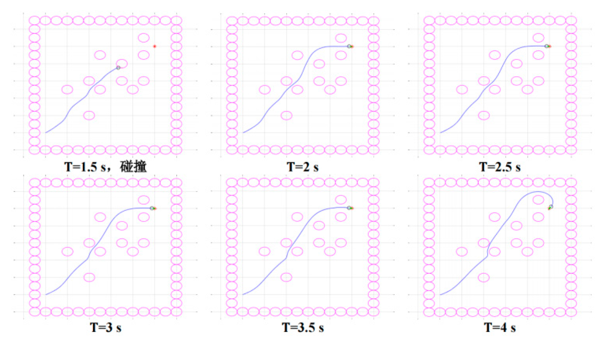
Figure 8.
Example of the results of the robot egg collecting navigation test.
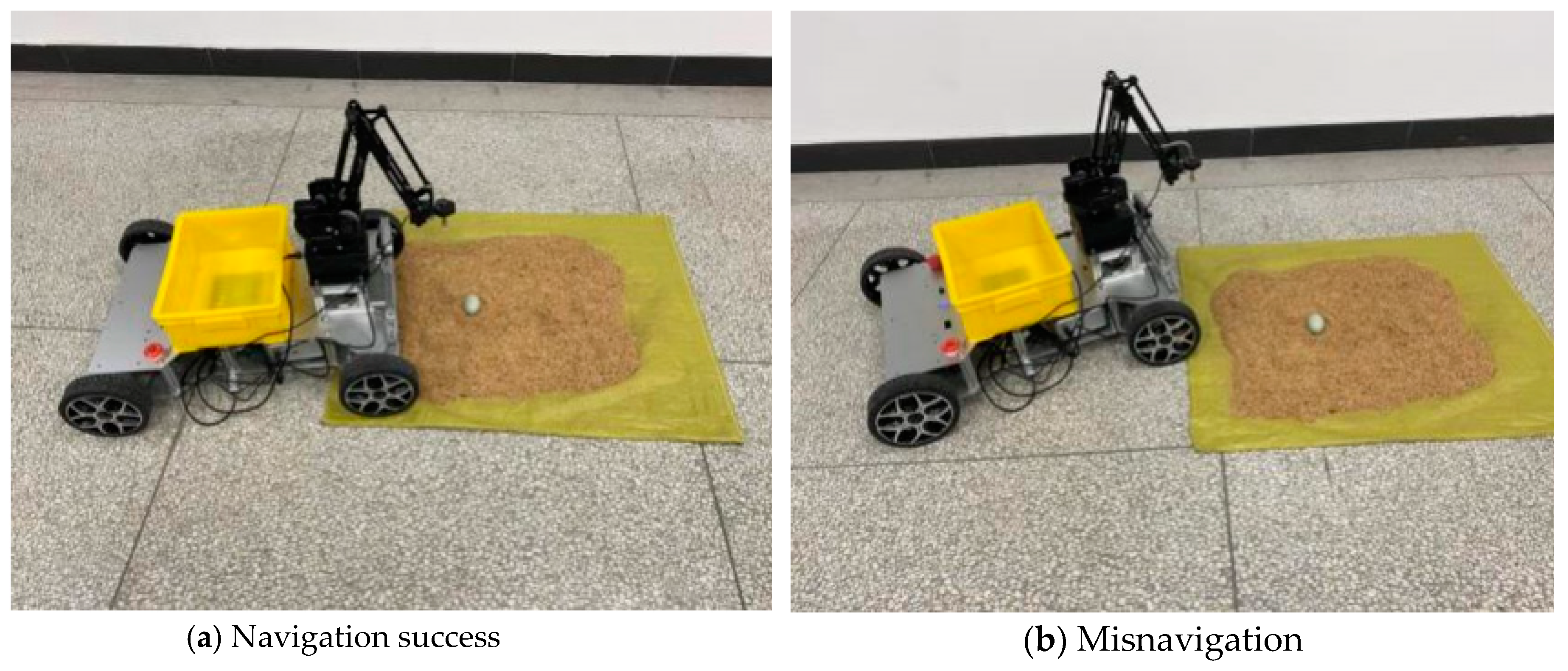

Table 1.
Navigation test results.
| Sample number | First navigation | Second navigation | Third navigation | Fourth navigation | Fifth navigation |
|---|---|---|---|---|---|
| 3 | T | F | T | T | T |
| 5 | T | T | T | T | F |
| 8 | T | T | F | F | F |
| 10 | T | F | T | T | T |
| 17 | F | F | F | F | F |
| 24 | T | F | T | T | T |
| 25 | T | T | F | T | F |
| 29 | T | T | T | F | F |
| Total number of failures | 1 | 4 | 3 | 3 | 5 |
Disclaimer/Publisher’s Note: The statements, opinions and data contained in all publications are solely those of the individual author(s) and contributor(s) and not of MDPI and/or the editor(s). MDPI and/or the editor(s) disclaim responsibility for any injury to people or property resulting from any ideas, methods, instructions or products referred to in the content. |
© 2024 by the authors. Licensee MDPI, Basel, Switzerland. This article is an open access article distributed under the terms and conditions of the Creative Commons Attribution (CC BY) license (http://creativecommons.org/licenses/by/4.0/).
Copyright: This open access article is published under a Creative Commons CC BY 4.0 license, which permit the free download, distribution, and reuse, provided that the author and preprint are cited in any reuse.


