
Submitted:
15 November 2024
Posted:
18 November 2024
You are already at the latest version
Abstract
The AlCoCrFeNi high entropy alloys are a novel structural material with wide application prospects. In order to investigate the influence of Al and Cr elements on the structure and properties of the alloys, AlxCr1-xCoFeNi (x=0.1, 0.2; 0.3, 0.4, 0.5) HEAs were prepared by mechanical alloying and spark plasma sintering. The microstructure and properties of the AlxCr1-xCoFeNi were analysed using XRD, SEM, EDS, electrochemical workstations, hardness measurement, friction and wear measurement, and room temperature compression measurement. The hardness and friction measurement results demonstrate that when x = 0.1, the crystal structure of Al0.1Cr0.9CoFeNi is composed of dual FCC phases and a trace of σ phase. With the increment of Al content, part of the FCC phase is transformed into BCC phase. When x=0.2~0.5, the alloy is composed of dual FCC phases, BCC phase and a trace σ phase. The Al0.5Cr0.5CoFeNi alloy exhibits the most favourable corrosion resistance, with a self-corrosion voltage of 0.202 V in a 3.5 wt.% NaCl solution. The hardness of alloy increases with the increasing of Al content. The Al0.5Cr0.5CoFeNi alloy exhibits the highest hardness value of 412.6 HV. At the initial stage of friction measurement, the wear mechanism of AlxCr1-xCoFeNi was adhesive wear. As the test time increased, oxide layers began to form on the surface of the alloy, resulting in a gradual increase in the coefficient of friction. At this stage, the wear mechanism was characterised by both adhesive and abrasive wear. Once the oxide layers and the wear processes reached dynamic equilibrium, the friction coefficient stabilised, and the wear mechanism transitioned to abrasive wear. Once the oxide layer and the wear process have reached dynamic equilibrium, the friction coefficient tends to stabilise gradually, and the wear mechanism is changed to abrasive wear. Al0.1Cr0.9CoFeNi has the smallest coefficient of friction of 0.513. Al0.5Cr0.5CoFeNi had the longest compression plateau and the greatest compression strain (59.7%) in the compression tests at room temperature.
Keywords:
High-entropy alloys
; mechanical alloys
; spark plasma sintering
; tafel testing
; friction wear performance
; compression performance
1. Introduction
High-entropy alloys (HEAs), a novel class of multi-principal element alloys, brought a new era in the study of alloy materials [1]. The presence of five or more elements in close proximity to the iso-atomic ratio endows alloys with high configurational entropy, which confers upon HEAs the capacity to form stable simple solid solution phases. This, in turn, endows HEAs with exceptional mechanical properties and commendable corrosion resistance [2]. Among the numerous HEAs systems, the single-phase face-centred cubic (FCC) structure of CoCrFeNi-based high-entropy alloys exhibits remarkable plasticity, machinability and corrosion resistance, as evidenced by research [3]. It is anticipated that this material will emerge as a novel structural option for use in environments prone to corrosion. Although the strength and hardness of the alloy are relatively low, these properties can be significantly enhanced by the addition of elements [4,5], particle dispersion strengthening [6], optimising the preparation process [7,8], and heat treatment, among other methods, provided that the plasticity of the alloy is maintained. This will facilitate the wider application of the FCC-phase HEAs in industrial production and life. The (CoFeNi)84Ti8V8 alloy, which was introduced with L12 nano-strengthening, demonstrated an increase in yield strength and ultimate tensile strength by 428% and 215%, respectively, in comparison to the un-strengthened condition. FCC equiatomic FeCoNi alloys with a grain size of approximately 10 nm and a thickness of approximately 0.2 mm were prepared by electrodeposition in an aqueous solution, exhibiting ultimate tensile strengths up to 1.6 GPa. The microstructure and properties of HEAs are directly related to the preparation process. Spark plasma sintering (SPS) is an advanced powder metallurgy method for solidifying high entropy alloy powders. The high-energy plasma during the sintering process enables rapid heating of the alloy powder, resulting in a fine and uniform microstructure [9]. Furthermore, the alloy remains in the high-temperature region for a brief period, which is conducive to the maintenance of the substable structure.
As-cast CoCrFeNi high-entropy alloys typically exhibit an FCC phase structure. The higher melting point and larger atomic radius of the Cr element impart a proclivity for the CoCrFeNi-based alloys to form a BCC phase. The non-equilibrium solidification process, mechanical alloying (MA), and other techniques facilitate the formation of a substable BCC phase, which tends to increase with the increase in the content of the Cr element. When the Cr content in an alloy is elevated in certain regions, a high Cr σ phase is formed at the grain boundaries. The Al element has a stronger bonding affinity with CoCrFeNi high entropy alloys with larger atomic radii, and its incorporation into the alloying system intensifies the lattice distortions. This enables the fabrication of HEAs with exceptional mechanical properties, including FCC+BCC or BCC+B2 dual phases, as evidenced by references [10,11,12]. In conclusion, the increase in the content of Al and Cr elements in the HEA system will result in an increased tendency for the FCC to BCC transformation. A significant number of studies have examined the influence of Al content on the microstructure and properties of CoCrFeNi-based HEAs. These studies have demonstrated that the introduction of Al into the alloys without altering the original alloying system may superimpose the effects of Al and Cr elements, thereby promoting the phase transition. In order to mitigate this effect, the present work employs the replacement of a portion of the Cr elements in the alloy system with Al elements, and the preparation of AlxCr1-xCoFeNi (x=0.1, 0.2, 0.3, 0.4, 0.5) high entropy alloys by MA+SPS technique.
The objective of this study is to investigate the impact of Al and Cr element on the microstructure and properties of CoCrFeNi alloys and to provide insights for the design and property regulation of CoCrFeNi HEAs. The study will provide a foundation for future research on the design and regulation of CoCrFeNi HEAs.
2. Materials and Methods
The compositions of the AlxCr1-xCoFeNi HEAs were designed according to the specified parameters and the mass of each specimen was 20 g. The elemental powders employed in the experiments were of the highest possible purity (99.9%) and the particle sizes fell below 25 µm (Zhongmai Metal Material Co., Ltd). The metal powders were subjected to mechanical alloying in a high-energy planetary ball mill (F-P4000E, Focucy, Changsha, China) for 40 hours at 350 rpm. The grinding balls were 3 mm and 10 mm in diameter and comprised hard stainless steel. The mass ratio of the grinding balls to the metal powder was 1:1. The weight ratio of the metal powder to the grinding balls was 1:5. The ball-milled powders were subsequently subjected to sintering in a discharge plasma sintering furnace (SPS, 100T-20-III, Chenhua Electric Furnace Co., Ltd., Shanghai, China). The sintering temperature was 1000 °C, the holding time was 15 minutes, and the applied pressure was 1 t. The sintered specimen was a cylinder with a diameter (Ø) of 20 mm and a height (h) of 8 mm. Figure 1 depicts the experimental schematic for the preparation of HEAs.
The alloy specimens were subjected to corrosion using a diluted aqua regia solution (HCl:HNO3=1:3) for a period of 10 to 15 seconds following a pre-grinding and polishing treatment. The physical phase of the alloys was analysed by X-ray diffraction (XRD) using a Cu target and a Bruker Advance D8 XRD analyser (Germany). The X-ray diffraction (XRD) tests were conducted at a tube current of 40 mA, a tube voltage of 40 kV, and a scanning angle of 10° to 90°. The microstructure of the specimens were characterised by scanning electron microscopy (SEM, ZEISS, EVO-18, Germany) and energy spectrometry (EDS, Oxford Instruments, X-max, UK). The electrochemical properties of the alloys were investigated utilising a three-electrode system in conjunction with an electrochemical workstation (Princeton Applied Research, PARSTAT 4000A, USA). The experiments were conducted at 25 °C in a 3.5 wt.% NaCl solution, during which the alloy specimen, saturated calomel (SCE) and Pt served as the working, reference and auxiliary electrodes, respectively. The dynamic potential polarization curves (Tafel curves) of the alloys were tested after stabilization of the open-circuit potentials at test voltages of -400 mV to 400 mV and scanning speeds of 2 mV/s. Following the completion of the tests, the microstructure of the alloys was characterised by SEM and EDS analyses.
The hardness of the alloys was quantified by means of a Vickers hardness tester (Huayin Testing Instruments Co., HVS-50, Laizhou, China) with a load of 10 kgf and a holding time of 10 s. The friction properties of the alloys were analysed at room temperature by means of a friction and wear tester (RTEC Instruments, MFT-5000, USA). The counter-wear materials utilised in the tests were GCr15 grinding balls with Ø 6 mm. The dimensions of the alloy specimen were Ø7 mm×3 mm in thickness. The test was conducted at a rotational speed of 120 r/min for a duration of 600 s, with a load of 10 N and a friction radius of 1.5 mm. Universal testing machine (WDW-200, Shanghai, China) was used to test the room temperature compression properties of the alloy, the specimen size of Ф7 mm × 8 mm cylindrical specimen, load 80 kN, loading speed 3 mm / min.
3. Results and Discussion
3.1. Phase and Microstructure of AlxCr1-xCoFeNi
The XRD patterns of the AlxCr1-xCoFeNi HEAs are shown in Figure 2(a). The diffraction peak angles and peak intensities of the FCC phase identified in the figure were similar to the standard diffraction diagram (PDF#04-0850) for Ni, corresponding to crystallographic indices (1 1 1), (2 0 0) and (2 2 0). Similarly, the BCC phase corresponded to the standard diffraction diagram for Cr (PDF#06-0694) with crystallographic indices (1 1 0), (2 0 0) and (2 1 1). As shown in Figure 2(a), the alloy consisted of FCC + σ phase when x = 0.1 and BCC peaks were observed in the XRD pattern when x ≥ 0.2. As the value of x increased, new diffraction peaks of BCC phase were observed in the XRD pattern and the peak intensity gradually increased. According to the parameters related to high entropy alloys calculated in Table 1, the addition of Al to the CoCrFeNi system caused an increase in the mixing entropy (∆Gmix) of the alloys from 1.47R to 1.56R, a decrease in the mixing enthalpy (∆Hmix) from -4.98 to -9.38 KJ/mol, and an increase in the difference in atomic radii (δ) from 2.30 % to 4.47 % [13]. Combined with the phase prediction criterion for high entropy alloys, the crystal structures of the AlxCr1-xCoFeNi HEAs were transformed from the FCC phase to the FCC+BCC phase. The XRD patterns of the alloys were found to be compatible with the phase prediction results. From the magnified spectra of the 43°~45° region in Figure 2(a), it was observed that the main peak of the FCC phase gradually shifted to the left with the increment of x from 0.1 to 0.5, and part of the FCC phase transformed into the BCC phase. The explanation for this is that the Al element increased the lattice distortion to make the crystal plane spacing wider, so the peak shift and phase transition occurred to release the distortion energy [14].
Figure 2(b) shows the results of the back-convolution operation on the diffraction peaks in the grey region of Figure 2(a) [15]. Based on the results, it could be inferred that the XRD pattern of Al0.1Cr0.9CoFeNi was formed by the superposition of diffraction peaks with different structures. Combining the microstructure SEM images and the EDS results of the Al0.1Cr0.9CoFeNi alloy in Figure 3, the structure of the alloy consisted of two FCC phases with a large variation in Cr element content and tiny σ phases. In Figure 3, region 1 represents the Cr-rich FCC phase and region 2 represents the Cr-poor FCC phase. Vaidya et al. divided the mechanical alloying process of CoCrFeNi alloys into two parts: (1) Ni and Co dissolved into Fe of FCC to form Cr-poor Fe(Ni,Co) FCC phase solid solution; and (2) Fe diffused into Cr to form Fe-Cr BCC phase solid solution [16]. After the CoCrFeNi alloy powder was sintered by SPS at 900°C, the BCC phase Fe-Cr solid solution was transformed into Cr-rich FCC phase, and the microstructure of the bulk alloy consisted of Cr-poor FCC phase + Cr-rich FCC phase + few σ phases [4], which was consistent with the XRD physical analysis results of the AlxCr1-xCoFeNi HEAs in this work. Ding et al [17] found that after replacing some of the Mn elements with Al elements in a CrMnFeCoNi high-entropy alloy with little interstitial concentration fluctuation, the atomic distribution of the alloy showed significant inhomogeneity, and obvious fluctuations in compositional concentration and frequent transverse slippage of dislocations were observed. Al and Cr elements contributed to the elemental bias phenomenon in AlxCr1-xCoFeNi HEAs, and the metal atoms could only diffuse to a small extent during SPS sintering, which largely maintained the inhomogeneity of the elemental distribution. This could be the reason why the alloy structures consist of Cr-poor and Cr-rich phases.
Figure 4 shows the SEM images of AlxCr1-xCoFeNi HEAs in the Cr-poor regions with x = 0.1, 0.2, 0.3, 0.4, 0.5 according to Figure 4(a) to Figure 4(e). Table 2 shows the EDS analysis results of the marked regions in Figure 4. As shown by the results of the SEM and EDS analyses, the Cr-poor region of the alloys consisted of isometric crystals of Cr-poor FCC and Cr-rich σ at x = 0.1. At x = 0.2, the Cr-poor region of the alloys consisted of isometric crystals of Cr-poor FCC, Cr-rich σ and Al-rich BCC. The number of BCC phases gradually increased as x increased from 0.1 to 0.5.
3.2. Electrochemical Performance
Figure 5 illustrates the Tafel test curves of AlxCr1-xCoFeNi HEAs in a 3.5 wt.% NaCl solution, along with the self-corrosion potential (Ecorr) and the self-corrosion current density (Icorr) of the alloy, which were calculated by the extrapolation method [18]. It was observed that the value of Ecorr was maximum at -0.202 V when x = 0.5, and Al0.5Cr0.5CoFeNi exhibited the least tendency to corrode in neutral solution [19]. Its corrosion resistance was slightly superior to that of Al0.5CuFeNiCoCr alloy prepared by powder metallurgy by Jiang et al [20].
The self-corrosion current density of AlxCr1-xCoFeNi alloys composed of multiphase was far higher than that of single-phase high-entropy alloys of similar composition. The reason is that the electrochemical corrosion process of the alloy is selective corrosion, not pitting corrosion, and Cl− adsorbed on the surface of the alloy when the activated dissolution of the alloy occurs, which accelerates the corrosion rate and makes it impossible to form a passivation film on the surface of the alloy. Based on Faraday's law, it was known that the density of corrosion current and the corrosion rate is proportional to the relationship. The corrosion rate of Al0.4Cr0.6CoFeNi was minimum, and its corrosion resistance was better than other alloys in this work.
Figure 6 presents the SEM images of the surface of AlxCr1-xCoFeNi HEAs and the results of the EDS analysis of the marked areas following the Tafel test. The comprehensive analysis indicates that the potential of the Cr element in neutral solution NaCl is higher than that of the Al and Fe elements. The Cr-rich FCC phase is the cathode, and the cathodic reaction is 1/2O2+H2O+2e−→2OH−. The bias of the Cr element is the reason for the selective corrosion of the alloy. As the value of x increases from 0.1 to 0.5, the number of Cr-rich FCC phases of the AlxCr1-xCoFeNi HEAs decreases, and the cathode area decreases in parallel. Consequently, as the x value of the Al elemental content increases, the self-corrosion current density decreases, the self-corrosion potential of the alloy gradually increases, the corrosion resistance is improved, and the Al0.5Cr0.5CoFeNi alloy exhibits the most favourable corrosion resistance.
3.3. Hardness and Wear Resistance
The Vickers hardness of AlxCr1-xCoFeNi is listed in Table 3. Among the alloys, Al0.5Cr0.5CoFeNi exhibits the greatest Vickers hardness, reaching 412.6 HV, which is higher than that of FeCoCrNi prepared by a similar preparation process [22]. The number of BCC phases in AlxCr1-xCoFeNi was found to be positively correlated with the aluminium content. The presence of fewer slip systems in the BCC phase than in the FCC phase results in less ease of dislocation movement. Consequently, Al0.5Cr0.5CoFeNi with a greater number of BCC phases exhibits higher hardness [14].
As illustrated in the graphical representation of the friction coefficient-time for the AlxCr1-xCoFeNi HEAs (Figure 7), the experimental procedure is divided into three distinct phases. During the initial phase of the test (t ≤ 50 s), the predominant wear mechanism is adhesive wear. The friction coefficient begins at a low value and gradually increases as the grinding balls slide relative to the alloy surface, due to plastic deformation and solid welding, which causes the alloy particles to adhere to the surface of the grinding balls. (2) As the test progresses (50 s < t ≤ 400 s), the wear mechanism transitions to a combination of adhesive and abrasive wear. As a consequence of the generation of frictional heat, hard oxide particles begin to appear on the alloy surface, and these particles are also involved in the process of friction [23]. The surface of the alloy is severely worn, and the coefficient of friction is increasing and reaches its peak value. (3) In the final stage of the test (t > 400 s), oxidative wear becomes the main mechanism. As a result of the generation of frictional heat, a sufficiently thick and continuous oxide layer is formed on the alloy friction surface. This oxide layer serves to protect the alloy surface from adhesive and abrasive wear. At this point, the formation of the oxide film and the wear rate reach an equilibrium, and the coefficient of friction tends to stabilise after a slight decrease. When the oxide film is stabilised, the coefficient of friction tends to increase gradually with the increase in x-value, and the lowest coefficient of friction of 0.513 was found for Al0.1Cr0.9CoFeNi. The wear resistance of AlxCr1-xCoFeNi is better than that of FeCoCrNi alloys produced by laser melting and cladding [24].
Figure 8 presents the topographic images and compositional analysis of the wear marks of the AlxCr1-xCoFeNi HEAs following the completion of the friction test. The values of x correspond to the following compositions: 0.1, 0.2, 0.3, 0.4, 0.5. In Figs. 8(a)~8(e), respectively, the scale bar represents depth, with 0 mm corresponding to the position of the original plane of the alloy specimen. The area with discontinuous and darker colours in the wear marks indicates the position of the oxide film flaking off. The abrasion marks of oxide wear are relatively flat in Figs. 8(a), 8(b), and 8(c), while the abrasion marks in Figs. 8(d) and 8(e) contain grooves of varying depths. Figure 8(f) depicts a longitudinal cross-section of the abrasive wear marks. The abrasive wear marks of Al0.1Cr0.9CoFeNi and Al0.2Cr0.8CoFeNi are shallow, with a relatively small abrasion amount. The curves of The Al0.3Cr0.7CoFeNi exhibited the widest and deepest abrasive wear marks, with the greatest amount of material removed. The Al0.4Cr0.6CoFeNi and Al0.5Cr0.5CoFeNi exhibited significant fluctuations in depth, indicating that the abrasive wear was clearly characterised. The EDS analysis of the midpoint of the abrasive marks revealed a high concentration of oxygen (O) elements, indicative of an oxide film resulting from oxidative wear. This finding was corroborated by the analysis of the friction coefficient-time curve.
The SEM images of the friction positions and the EDS analysis results of the marked points demonstrate that the friction positions contain a considerable number of O elements. Furthermore, the even fine abrasion marks on the oxide film can be clearly observed in Figure 8(d) and Figure 8(e), which are the typical characteristics of oxidative wear and coincide with the results of the analysis of the friction coefficient-time curves. In Figure 8(a), position 1 is the oxide film, and position 2 is the surface of the alloy matrix, and fine abrasion marks can be observed. The oxide film generated during the friction process is harder and more brittle than the alloy, and it is susceptible to rupture and the formation of cracks, or even spallation, when the temperature is repeatedly raised and lowered during the friction process [25]. Therefore, it can be seen that the friction process of AlxCr1-xCoFeNi HEAs is positively correlated with the rate of oxide film formation. The oxidation process in the oxidative wear process is the diffusion process of elements to the friction surface, and the diffusion rate determines the generation rate of the oxide film. With the increase of the Al element content, the BCC phase in AlxCr1-xCoFeNi HEAs increases, and the lattice energy of the BCC phase is higher than that of the FCC phase when the chemical composition is similar. This is not conducive to the mobility of metal elements. Consequently, the Al0.1Cr0.9CoFeNi alloy with a FCC phase structure exhibits the lowest friction coefficient, which tends to increase gradually with the increase of the x value.
3.4. Hardness and Wear Resistance
The room temperature stress-strain curves and compressive strengths of AlxCr1-xCoFeNi HEAs are shown in Figure 9. It can be seen that there was no fracture of the specimen during the compression test. The compression curves of the alloys show typical compression characteristics of plastic materials when x = 0.1, 0.2, 0.3 and their compressive strengths are 270.94 MPa, 351.58 MPa and 321.87 MPa respectively. It is worth noting that the compression curves of the alloys have a plateau period after the elastic deformation and enter the plastic deformation stage after the yielding stage when x = 0.4, 0.5. The curves are similar to the compression test curves of the porous Cu-Cr-Zr alloy materials[26], but unlike them, the compression plateau may be due to the phase transformation of the substable BCC phase generated during the SPS process[27,28]. As the content of Al element increases and the content of Cr element decreases, the number of BCC phases in the alloys increases, which makes Al0.4Cr0.6CoFeNi and Al0.5Cr0.5CoFeNi have strong impact resistance and much higher plastic deformation strain than the other three alloys. Among them, Al0.5Cr0.5CoFeNi has the longest compression plateau period and the largest compression strain of 59.7%.
4. Conclusions
The study aimed to elucidate the impact of aluminium (Al) and chromium (Cr) on the microstructure and properties of CoCrFeNi high entropy alloys (HEAs) in the AlxCr1-xCoFeNi system (where x=0.1, 0.2, 0.3, 0.4, 0.5). These alloys were prepared by a combination of mechanical alloying and plasma hot press sintering. A comprehensive analysis of phase and microstructure, electrochemical testing, evaluation of hardness, friction and compression properties leads to the following conclusions:
- (1)
- The AlxCr1-xCoFeNi HEAs are multiphase and comprise a Cr-rich FCC phase, a Cr-poor FCC phase, and a Cr-rich σ phase. The Al0.1Cr0.9CoFeNi alloy is similarly multiphase, with a Cr-rich FCC phase, a Cr-poor FCC phase, and a Cr-rich σ phase. As the aluminium content increases (x=0.2~0.5), a portion of the FCC phase transitions into the BCC phase, accompanied by an increase in the BCC phase fraction. It can be observed that an imbalance of chromium aggregation occurs in the alloy, with this decreasing with increasing aluminium content.
- (2)
- The results of electrochemical tests conducted in a 3.5 wt% NaCl solution demonstrated that the alloy exhibited selective corrosion, with the Cr-poor FCC phase acting as the cathode. The self-corrosion potential of the alloy increases with increasing aluminium content, reaching a maximum value for Al0.5Cr0.5CoFeNi, which indicates optimum corrosion resistance.
- (3)
- The hardness of the alloys increased with the increase in the elemental content of Al. The Al0.5Cr0.5CoFeNi alloy exhibited the highest hardness, with a measured value of 412.6 HV. During the friction testing, the coefficient of friction of the alloys exhibited a gradual increase over time. This was accompanied by a transition in the wear mechanism, which initially manifested as adhesive wear, subsequently evolving into a combination of adhesive and abrasive wear, and finally, oxidative wear. The friction coefficient tends to stabilise when the oxide film stabilises and reaches equilibrium with the wear process. At this point, the minimum friction coefficient observed for the Al0.1Cr0.9CoFeNi alloy is 0.513. This suggests that a lower aluminium content is beneficial in reducing the friction coefficient during the stable wear phase.
- (4)
- The results of the compression tests show that the number of substable BCC phases in the alloy increases at x = 0.4 and 0.5, a compression plateau appears in the room temperature stress-strain curve and the impact strength of the alloy is improved. Al0.5Cr0.5CoFeNi has the longest compression plateau period and the largest compression strain of 59.7%.
Author Contributions
Conceptualization, Xiangran Meng; Data curation, Chunpin Geng and Chongshuo Wang; Funding acquisition, Xiangran Meng; Investigation, Xiangran Meng; Methodology, Haifeng Ren and Xiaoying Guo; Resources, Chunpin Geng and Chongshuo Wang; Supervision, Gang Li; Validation, Haifeng Ren and Xiaoying Guo; Writing – original draft, Xiangran Meng; Writing – review & editing, Gang Li, Sinan Li and Ying Tao. All authors have read and agreed to the published version of the manuscript.
Funding
This work was financially supported by Foundation of Liaoning Educational Committee(No. [2022]LJKQZ20222305), Liaoning Provincial Engineering Research Center for High-Value Utilization of Magnesite (LMNZ2024020103) and the Key Laboratory of Mineral High Value Conversion and Energy Storage Materials of Liaoning Province (Open Fund Project No. ME23-06).
Institutional Review Board Statement
Not applicable.
Informed Consent Statement
Not applicable.
Data Availability Statement
All data are provided in the article.
Acknowledgments
The authors acknowledge the financial support from Foundation of Liaoning Educational Committee (No. [2022]LJKQZ20222305), Liaoning Provincial Engineering Research Center for High-Value Utilization of Magnesite (LMNZ2024020103) and the Key Laboratory of Mineral High Value Conversion and Energy Storage Materials of Liaoning Province (Open Fund Project No. ME23-06). This study was also supported by the Key Laboratory of Optimisation and Application of Low-grade Non-Associated Iron Ore in Benxi, Liaoning Province, China.
Conflicts of Interest
The authors declare no conflicts of interest.
References
- Kong, K.; Hyun, J.; Kim, Y.; Kim, W.; Kim, D. Nanoporous Structure Synthesized by Selective Phase Dissolution of AlCoCrFeNi High Entropy Alloy and Its Electrochemical Properties as Supercapacitor Electrode. Journal of Power Sources 2019, 437, 226927. [Google Scholar] [CrossRef]
- Liu, F.; Liaw, P.K.; Zhang, Y. Recent Progress with BCC-Structured High-Entropy Alloys. Metals 2022, 12. [Google Scholar] [CrossRef]
- Zhang, J.; Li, X.; Zhang, Y.; Zhang, F.; Wang, H. Sluggish Dendrite Growth in an Undercooled High Entropy Alloy. Intermetallics 2020, 119, 106714. [Google Scholar] [CrossRef]
- Vaidya, M.; Guruvidyathri, K.; Murty, B.S. Phase Formation and Thermal Stability of CoCrFeNi and CoCrFeMnNi Equiatomic High Entropy Alloys. Elsevier 2019. [Google Scholar] [CrossRef]
- Dasari, S.; Sharma, A.; Byers, T.A.; Glass, G.A.; Srivilliputhur, S.; Rout, B.; Banerjee, R. Proton Irradiation Induced Chemical Ordering in an Al0.3CoFeNi High Entropy Alloy. Applied Physics Letters 2021, 119, 161907. [Google Scholar] [CrossRef]
- Wang, L.; Wu, X.; Su, H.; Deng, B.; Liu, G.; Han, Z.; Su, Y.; Huang, Y.; Zhang, Y.; Shen, J. Microstructure and Mechanical Property of Novel L12 Nanoparticles-Strengthened CoFeNi-Based Medium Entropy Alloys. Materials Science and Engineering: A 2022, 840, 142917. [Google Scholar] [CrossRef]
- Zhou, X.; Chen, J.; Ding, R.; Wu, H.; Du, J.; He, J.; Wang, W.; Sun, W.; Liu, Y.; Sha, G.; et al. Carbon-Driven Coherent Nanoprecipitates Enable Ultrahigh Yield Strength in a High-Entropy Alloy. Materials Today Nano 2023, 22, 100331. [Google Scholar] [CrossRef]
- Watanabe, A.; Yamamoto, T.; Takigawa, Y. Tensile Strength of Nanocrystalline FeCoNi Medium-Entropy Alloy Fabricated Using Electrodeposition. Scientific Reports. [CrossRef]
- Yang, X.; Liang, Z.; Wang, L.W.; Zhang, H.; Wang, D.L. Interface Structure and Tensile Behavior of High Entropy Alloy Particles Reinforced Al Matrix Composites by Spark Plasma Sintering. Materials Science and Engineering: A 2022, 860, 144273. [Google Scholar] [CrossRef]
- Jin, X.; Liang, Y.; Bi, J.; Li, B. Enhanced Strength and Ductility of Al0.9CoCrNi2.1 Eutectic High Entropy Alloy by Thermomechanical Processing - ScienceDirect. Materialia 2020, 10, 100639. [Google Scholar] [CrossRef]
- Xiao, Y.; Chang, X.; Peng, X.; Fu, T. Heterogeneous Structure Induced Excellent Mechanical and Wear Properties in Co-Free FeCrAlNi Medium-Entropy Alloys. Journal of Materials Research and Technology 2022, 18, 4169–4180. [Google Scholar] [CrossRef]
- Xiong, W.; Wu, C.; Liu, Y.; Tu, H.; Su, X. Phase Stability and Microhardness of the AlxCr2-xCoFeNi High-Entropy Alloys. Journal of Phase Equilibria and Diffusion 2021. [Google Scholar] [CrossRef]
- Tsai, M.-H.; Yeh, J.-W. High-Entropy Alloys: A Critical Review. Materials Research Letters 2014, 2, 107–123. [Google Scholar] [CrossRef]
- Zuo, T.T.; Li, R.B.; Ren, X.J.; Zhang, Y. Effects of Al and Si Addition on the Structure and Properties of CoFeNi Equal Atomic Ratio Alloy. Journal of Magnetism and Magnetic Materials 2014, 371, 60–68. [Google Scholar] [CrossRef]
- Praveen, S.; Murty, B.S.; Kottada, R.S. Alloying Behavior in Multi-Component AlCoCrCuFe and NiCoCrCuFe High Entropy Alloys. Materials Science and Engineering: A 2012, 534, 83–89. [Google Scholar] [CrossRef]
- Praveen, S.; Murty, B.S.; Kottada, R.S. Phase Evolution and Densification Behavior of Nanocrystalline Multicomponent High Entropy Alloys During Spark Plasma Sintering. JOM 2013, 65, 1797–1804. [Google Scholar] [CrossRef]
- Ding, Q.; Zhang, Y.; Chen, X.; Fu, X.; Chen, D.; Chen, S.; Gu, L.; Wei, F.; Bei, H.; Gao, Y. Tuning Element Distribution, Structure and Properties by Composition in High-Entropy Alloys. Nature. [CrossRef]
- Kim, D.; Kim, K.; Park, J.; Chung, W.; Shin, B.-H. Microstructure and Corrosion Performance of High-Entropy Alloy and Austenite and Super Duplex Stainless Steels in 3.5% NaCl Solution. International Journal of Electrochemical Science 2023, 18, 100074. [Google Scholar] [CrossRef]
- Qiu, Y.; Gibson, M.A.; Fraser, H.L.; Birbilis, N. Corrosion Characteristics of High Entropy Alloys. Materials Science and Technology 2015, 31, 1235–1243. [Google Scholar] [CrossRef]
- Jiang, J.Y.; Du, J.H.; Yan, J.K.; Zhang, J.M.; Gan, G.Y. Preparation of AlxCuFeNiCoCr High-Entropy Alloy by Powder Metallurgy Method and Its Properties. Rare Metal Mat. Eng.(in Chinese) 2022, 51, 392–399. [Google Scholar] [CrossRef]
- Mahmoud, E.R.I.; Mohamed, L.Z.; Gepreel, M.A.; Ebied, S.; Abdelfatah, A. Corrosion Behavior of Cold-Rolled and Solution-Treated Fe36Mn20Ni20Cr16Al5Si3 HEA in Different Acidic Solutions. Materials 2022, 15. [Google Scholar] [CrossRef] [PubMed]
- Zhang, C.; Luo, X.; Ma, L.; Hou, L.; Huang, B.; Hu, R. Study on Microstructure and Properties of WC Particle-Reinforced FeCoCrNi-Matrix High Entropy Alloy Composites. Materials 2023, 16. [Google Scholar] [CrossRef] [PubMed]
- Vo, T.D.; Tran, B.; Tieu, A.K.; Wexler, D.; Deng, G.; Nguyen, C. Effects of Oxidation on Friction and Wear Properties of Eutectic High-Entropy Alloy AlCoCrFeNi2.1. Tribology International 2021, 160, 107017. [Google Scholar] [CrossRef]
- Wang, S.; Wang, L.; Yin, X.W. Microstructure and mechanical properties of laser cladding FeCoCrNiNb high entropy alloy coating, Rare Metal Mat. Eng. (in Chinese) 2023, 52, 1483–1489. [Google Scholar] [CrossRef]
- Gao, P.; Fu, R.; Liu, J.; Chen, B.; Zhang, B.; Zhao, D.; Yang, Z.; Guo, Y.; Liang, M.; Li, J. Influence of Plasma Arc Current on the Friction and Wear Properties of CoCrFeNiMn High Entropy Alloy Coatings Prepared on CGI through Plasma Transfer Arc Cladding. Coatings 2022, 12, 633. [Google Scholar] [CrossRef]
- Ma, Z.; Zhang, D.Z.; Liu, F.; Jiang, J.; Zhao, M.; Zhang, T. Lattice Structures of Cu-Cr-Zr Copper Alloy by Selective Laser Melting: Microstructures, Mechanical Properties and Energy Absorption. Materials & Design 2020, 187, 108406. [Google Scholar] [CrossRef]
- Yang, Y.; Li, G.P.; Cheng, G.M.; Wang, H.; Zhang, M.; Xu, F.; Yang, K. Stress-Introduced α″Martensite and Twinning in a Multifunctional Titanium Alloy. Scripta Materialia 2008, 58, 9–12. [Google Scholar] [CrossRef]
- Qian, B.; Li, X.; Wang, Y.; Hou, J.; Liu, J.; Zou, S.; An, F.; Lu, W. An Ultra-Low Modulus of Ductile TiZrHfTa Biomedical High-Entropy Alloys through Deformation Induced Martensitic Transformation/ Twinning/ Amorphization. Advanced Materials 2024, 2310926. [Google Scholar] [CrossRef]
Figure 1.
Experimental schematic for the preparation of HEAs.
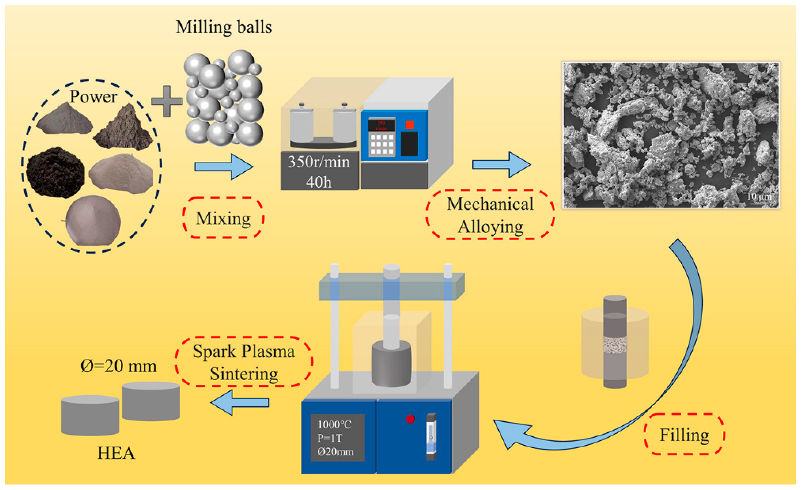
Figure 2.
This is a figure. Schemes follow another format. If there are multiple panels, they should be listed as: (a) XRD patterns of AlxCr1-xCoFeNi alloys; (b) Deconvolution of diffraction peaks in the region marked by a gray rectangular box.
Figure 2.
This is a figure. Schemes follow another format. If there are multiple panels, they should be listed as: (a) XRD patterns of AlxCr1-xCoFeNi alloys; (b) Deconvolution of diffraction peaks in the region marked by a gray rectangular box.
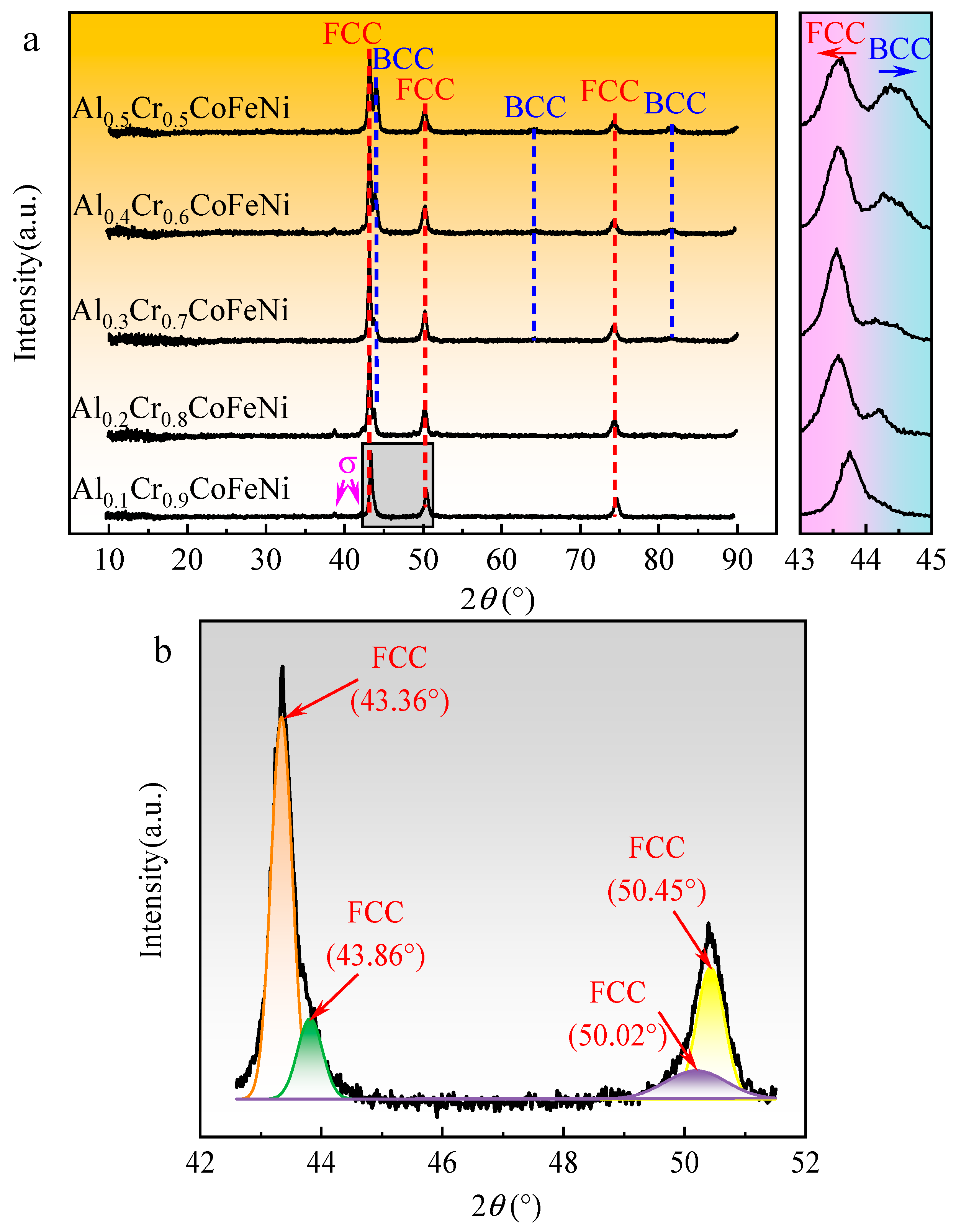
Figure 3.
Microstructure and compositional analysis of Al0.1Cr0.9CoFeNi.
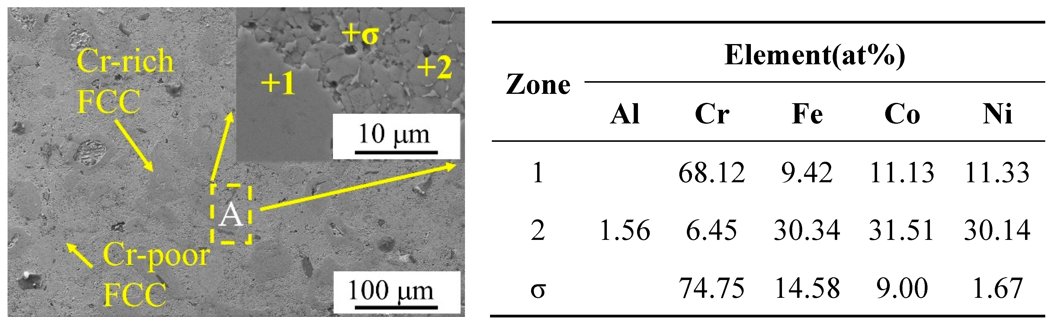
Figure 4.
Microstructure of Cr-poor regions in AlxCr1-xCoFeNi alloys: (a)x=0.1, (b)x=0.2, (c)x=0.3, (d)x=0.4, (e)x=0.5.
Figure 4.
Microstructure of Cr-poor regions in AlxCr1-xCoFeNi alloys: (a)x=0.1, (b)x=0.2, (c)x=0.3, (d)x=0.4, (e)x=0.5.
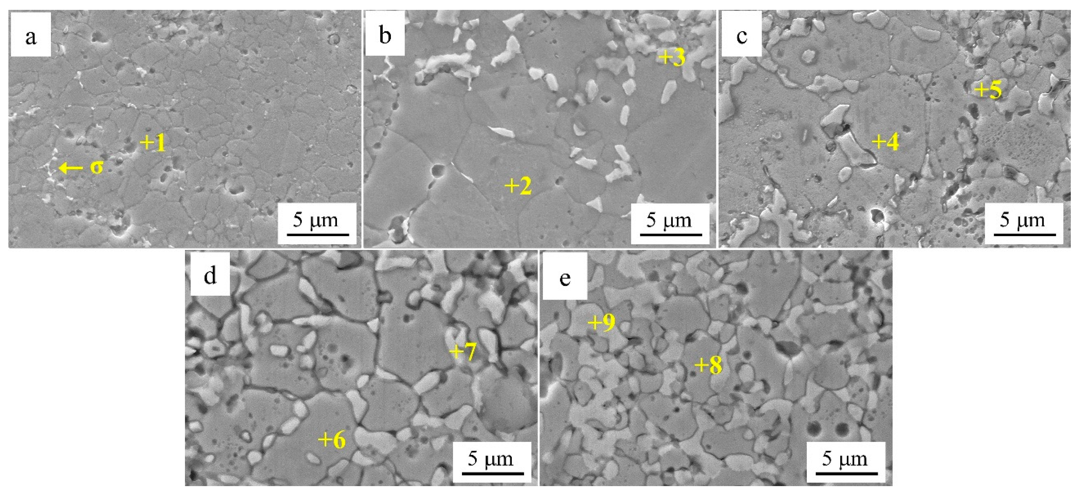
Figure 5.
Tafel test curves of AlxCr1-xCoFeNi HEAs.
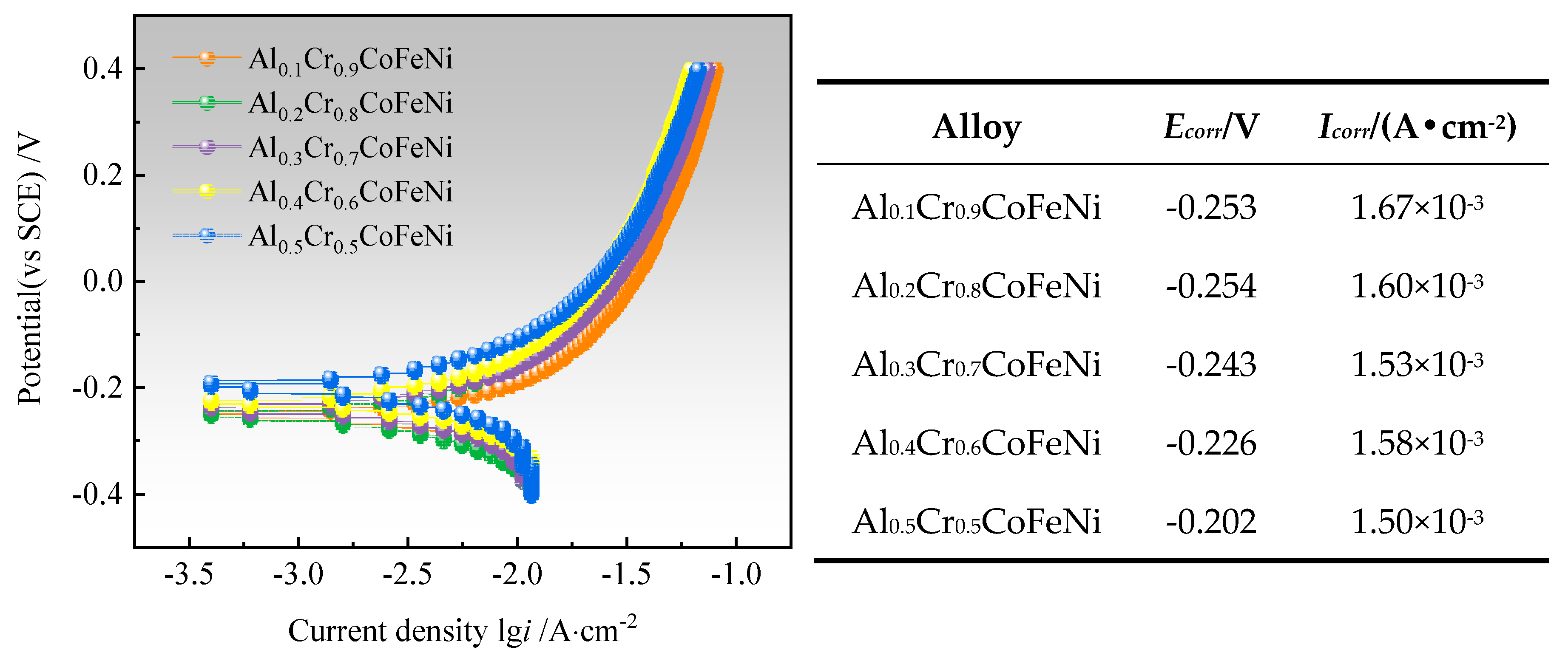
Figure 6.
Microstructure of AlxCr1-xCoFeNi alloys after Tafel testing: (a)x=0.1, (b)x=0.2, (c)x=0.3, (d)x=0.4, (e)x=0.5.
Figure 6.
Microstructure of AlxCr1-xCoFeNi alloys after Tafel testing: (a)x=0.1, (b)x=0.2, (c)x=0.3, (d)x=0.4, (e)x=0.5.
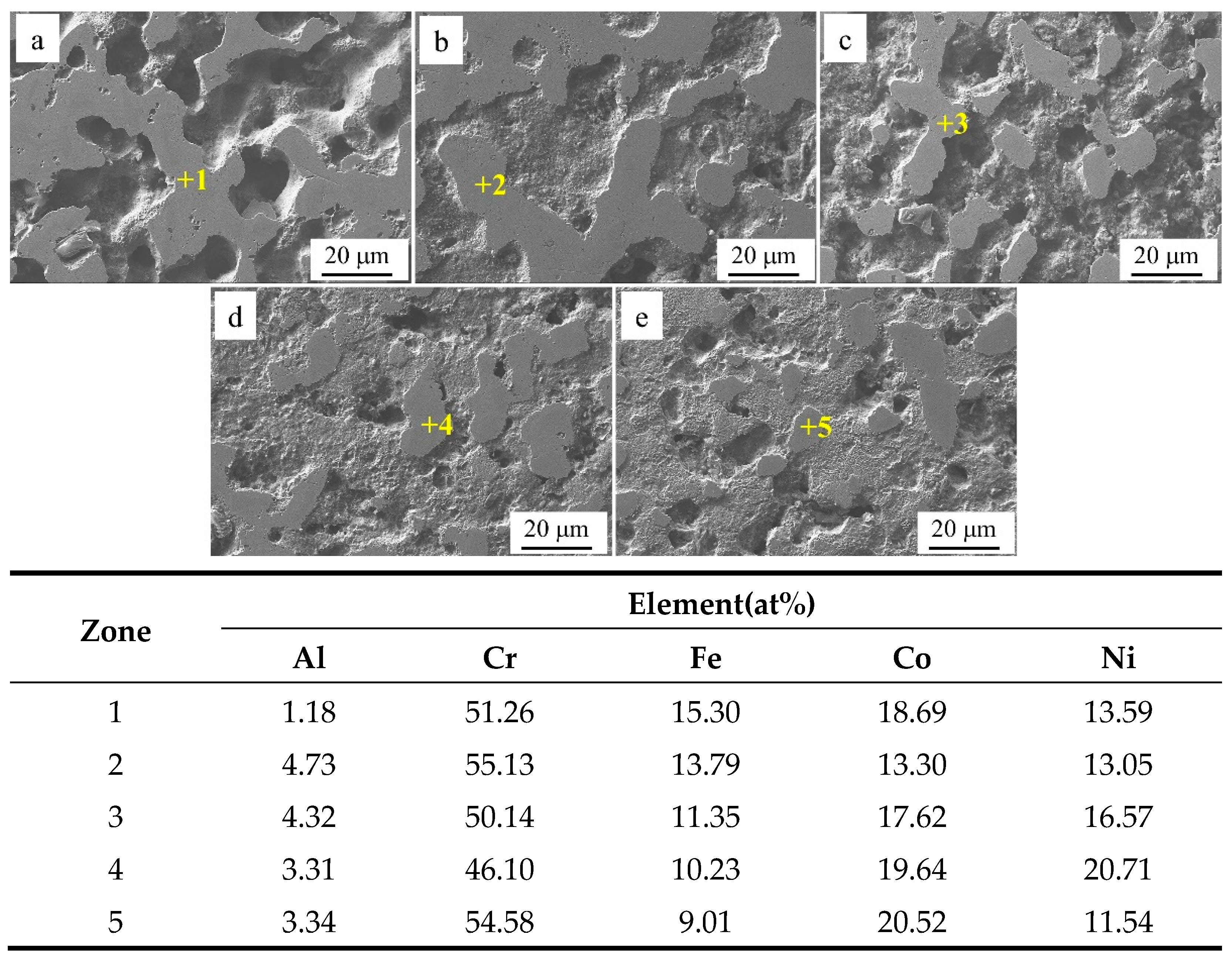
Figure 7.
Friction coefficient-time curves of AlxCr1-xCoFeNi alloys.
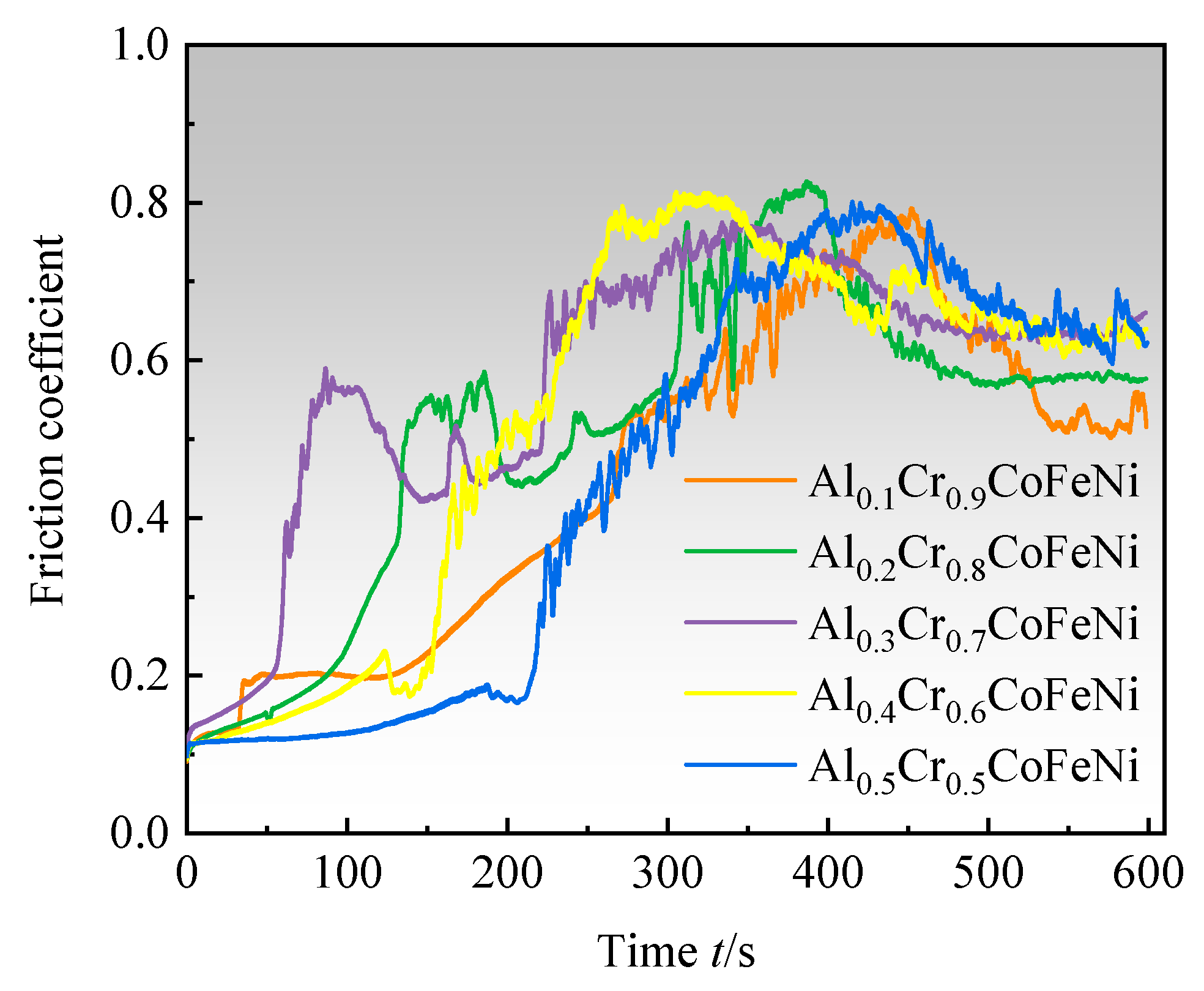
Figure 8.
Morphology and compositional analysis of AlxCr1-xCoFeNi HEAs wear marks: (a)x=0.1, (b)x=0.2, (c)x=0.3, (d)x=0.4, (e)x=0.5, (f)Longitudinal cross-section of abrasion marks.
Figure 8.
Morphology and compositional analysis of AlxCr1-xCoFeNi HEAs wear marks: (a)x=0.1, (b)x=0.2, (c)x=0.3, (d)x=0.4, (e)x=0.5, (f)Longitudinal cross-section of abrasion marks.
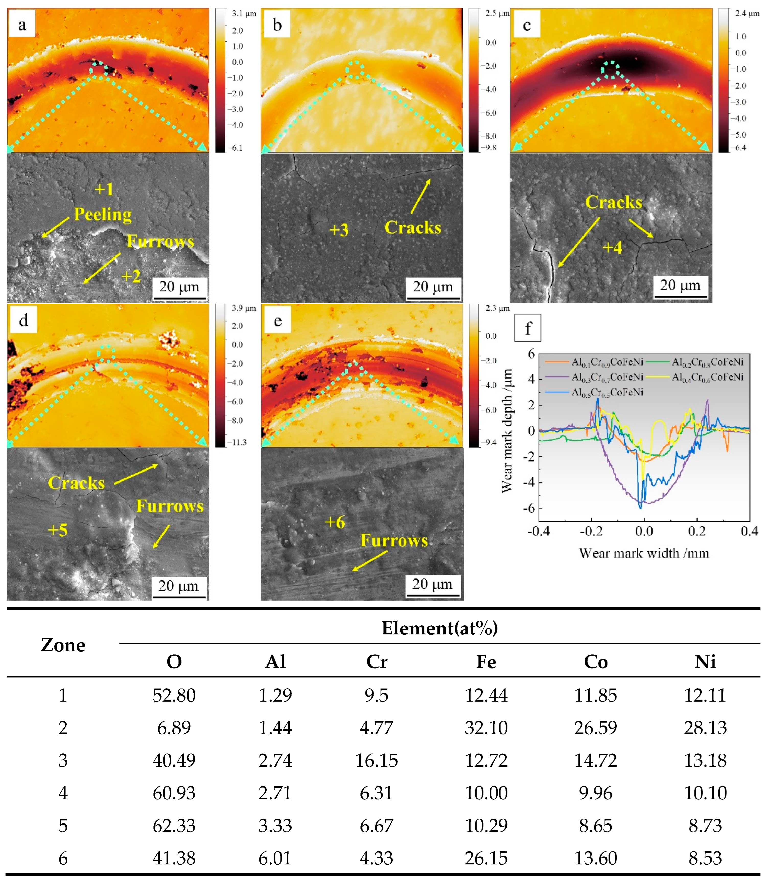
Figure 9.
Stress-strain curves at room temperature and compressive strength of AlxCr1-xCoFeNi HEAs.
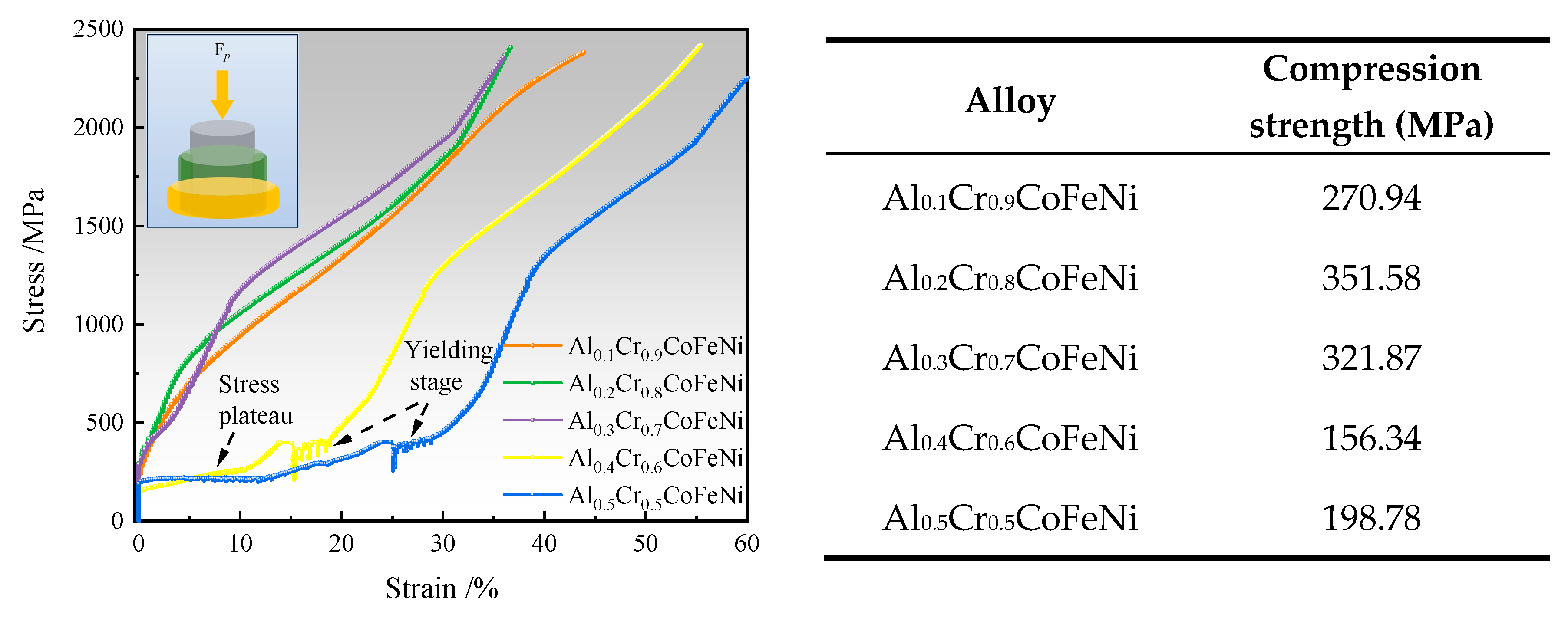

Table 1.
Calculated results of AlxCr1-xCoFeNi characteristic parameters.
| Alloy | ∆Gmix (K·mol) | ∆Hmix (KJ/mol) | δ (%) |
|---|---|---|---|
| Al0.1Cr0.9CoFeNi | 1.47R | -4.98 | 2.30 |
| Al0.2Cr0.8CoFeNi | 1.51R | -6.15 | 3.05 |
| Al0.3Cr0.7CoFeNi | 1.54R | -7.28 | 3.62 |
| Al0.4Cr0.6CoFeNi | 1.55R | -8.35 | 4.08 |
| Al0.5Cr0.5CoFeNi | 1.56R | -9.38 | 4.47 |
Table 2.
EDS analysis of marked zones in Fig.4(at%).
| Alloy | Zone | Al | Cr | Fe | Co | Ni |
|---|---|---|---|---|---|---|
| Al0.1Cr0.9CoFeNi | 1 | 3.25 | 17.86 | 23.54 | 26.78 | 28.57 |
| Al0.2Cr0.8CoFeNi | 2 | 8.82 | 22.43 | 18.01 | 25.50 | 25.23 |
| 3 | 10.59 | 8.44 | 14.59 | 22.93 | 43.45 | |
| Al0.3Cr0.7CoFeNi | 4 | 7.52 | 32.56 | 20.03 | 20.40 | 19.50 |
| 5 | 20.83 | 12.02 | 24.54 | 22.97 | 19.64 | |
| Al0.4Cr0.6CoFeNi | 6 | 11.55 | 23.27 | 12.23 | 32.09 | 20.87 |
| 7 | 27.59 | 4.78 | 17.92 | 22.31 | 27.41 | |
| Al0.5Cr0.5CoFeNi | 8 | 14.34 | 3.97 | 15.95 | 32.67 | 33.07 |
| 9 | 47.12 | 6.51 | 13.86 | 17.25 | 15.26 |
Table 3.
Vickers hardness of AlxCr1-xCoFeNi alloys.
| Alloy | Hardness (HV) |
|---|---|
| Al0.1Cr0.9CoFeNi | 311.66 |
| Al0.2Cr0.8CoFeNi | 324.60 |
| Al0.3Cr0.7CoFeNi | 360.34 |
| Al0.4Cr0.6CoFeNi | 403.42 |
| Al0.5Cr0.5CoFeNi | 412.60 |
Disclaimer/Publisher’s Note: The statements, opinions and data contained in all publications are solely those of the individual author(s) and contributor(s) and not of MDPI and/or the editor(s). MDPI and/or the editor(s) disclaim responsibility for any injury to people or property resulting from any ideas, methods, instructions or products referred to in the content. |
© 2024 by the authors. Licensee MDPI, Basel, Switzerland. This article is an open access article distributed under the terms and conditions of the Creative Commons Attribution (CC BY) license (http://creativecommons.org/licenses/by/4.0/).
Copyright: This open access article is published under a Creative Commons CC BY 4.0 license, which permit the free download, distribution, and reuse, provided that the author and preprint are cited in any reuse.


