
Submitted:
11 November 2024
Posted:
12 November 2024
You are already at the latest version
Abstract
Evaporation-induced electricity is a promising approach for sustainable energy generation, particularly suited for off-grid and Internet-of-Things (IoT) applications. Despite significant progress, the mechanism of electricity generation remains debated due to complex factors. In this study, we introduce a simplified capacitor-current circuit model to describe the behavior of evaporation-induced electricity. We validated this model using experimental data from wood-based nanogenerators with citric acid modified microchannels. The fitting results revealed a steady-state current of approximately 9.832 μA and initial peak current of 16.168 μA with a time constant of 621.395 s. These findings were explained by a hybrid model incorporating a capacitor and current source components and subsequent discharge through internal resistance. This simplified model paves the way for better understanding and optimization of evaporation-induced electricity, highlighting potential improvements in device design for enhanced performance.
Keywords:
Evaporation-induced electricity
; Capacitor-current circuit model
; energy conversion mechanism
; streaming potential
1. Introduction
In recent years, global warming has become increasingly pressing matter to the world due to fossil fuel consumption. The need for sustainable energy solution and reducing of carbon emissions has never been greater [1]. Among the various green energy technologies, a newcomer called evaporation-induced electricity has gained considerable interest [2,3]. This technology generates electric power from natural water evaporation, making it particularly suitable for remote, off-grid devices, especially Internet-of-Things (IoT) applications [4,5].
Despite significant progress in evaporation-induced electricity over the past decade, the underlying mechanism of electricity generation remains unclear. Various models have been proposed, ranging from traditional streaming potential [2] and ion concentration gradient [6,7] to more recent approaches like microbial electricity [8], ionovoltaic [9], pseudostreaming [10,11] and evaporative potential [12]. While each model provides a reasonable explanation, certain aspects remain unexplained [13].
In addition to efforts to understand the physical mechanisms of evaporation-induced electricity, progress has also been made in developing circuit models to explain the electrical characteristics of the working device. Notably, Mansouri et al. developed comprehensive mathematical formulations to describe the transient ion transport and charge storage/discharge features [14,15,16]. However, despite their accuracy and thoroughness, the mathematical complexity of these models limits their applicability in understanding, designing and optimizing real-world devices. To enhance the practicality and understanding of evaporation-induced electricity, a more accessible and adaptable model is needed.
Previously, our group reviewed the mainstream mechanisms and highlighted the advantages and limitations of each [13]. We also proposed a hybrid model that combines a capacitor and streaming current source to explain evaporation-induced electricity. In this work, we introduce this model as an innovative, simplified and robust alternative to existing models for explaining the electrical characteristics of evaporation-induced electricity. The proposed model will be validated using experimental data obtained from wood-based nanogenerators with modified aligned microchannels, chosen for their hydrophilicity and energy generation capabilities.
We will first discuss the limitations of the Mansouri’s model and explain the need for a simplified alternative. Then, we will introduce the simplified model, followed by an analysis of the wood-based nanogenerator’s device performance and data fitting to validate the model. We will also discuss the practical implications for device design, with a focus on porous structures and microchannel configurations. The primary goal is to develop a framework that balances simplicity with predicative accuracy, thereby accelerating the advancement of evaporation-induced electricity technology.
2. Development of the Simplified Capacitor-Current Circuit Model
2.1. Overview of the Mansouri Model
2.1.1. Introduction to the Electrical Analogy
Although many mechanisms have been proposed, it is widely agreed that the fundamental aspect of evaporation-induced electricity lies in ion transport within microstructures, driven by pressure differences or concentration gradients [5,17,18]. In this context, the electricity generation process inevitably involves the interaction between liquid and solid surfaces, forming an electrical double layer that contributes to charge buildup and transport [19], thereby influencing the overall device performance. As reviewed in our previously published work, several mechanisms exist beyond streaming potential theory, including ion concentration gradient, microbial electricity, ionovoltaic, pseudo-streaming and evaporation potential [13]. While each of these mechanisms provides valuable insights into the underlying physical processes, we believe it is crucial to study the electrical output characteristics using a circuit model based on the capacitor-current framework, which Mansouri et al. established as a solid foundation [14].
The benefits of capacitor-current model can be highlighted from three main perspectives. First, it directly captures the characteristics of electrokinetic processes, building on fundamental phenomena such as streaming currents and electrical double layers, which are easy to understand. Second, the capacitor-current model offers relative simplicity and physical clarity. By having an equivalent electrical circuit model, we can create a straightforward analogy to understand the essential behaviors of ion transport and charge storage. Third, this model aligns well with experimental data, as we will demonstrate later. In our wood-based nanogenerator, we observed an electricity output resembling the response of a combination of a capacitor and a current source, characterized by transient charge storage and gradual discharge over time. These results confirm the suitability of this model in explaining evaporation-induced electricity.
Based on the framework developed by Mansouri et al., the core elements of the electrical analogy consist of an internal capacitor (), a streaming current source () and the device’s internal resistance () [14], which arranged in parallel. represents charge accumulation within the electrical double layer of the microchannels. is generated by ion transport, driven by pressure difference caused by evaporation. accounts for ion transport resistance along the channels. The complete electrical analogy, including the external load resistance () and external current () is illustrated in Figure 1. This simplified electrical analogy effectively highlights the characteristics of the electricity output, capturing the practical aspects of power generation within the device.
2.1.2. Exploring Streaming Current: From Basics to Complex Models
The core of this electrical analogy is the streaming current, which arises from the pressure driven fluid flow transporting ions through a channel. In the context of evaporation-induced electricity, the fluid of interest is water. As water flows along the channel, the surface material undergoes hydrolysis, releasing charged ions. Then, the water flow carries these released charges generating an electric current that can be harvested through an external load. For a single channel, the physics governing this process can be summarized by using the following equation [14]:
where is the streaming current, the fluid permittivity reflecting its ability for charge storage, zeta potential of the channel surface material representing surface charge density, the dynamic viscosity of the fluid indicating the resistance to flow, the pressure difference applied across the channel, and the cross-section area and length of the channel. Specifically, is a correction factor based on the Debye length and the channel radius . When the channel radius is much larger than the Debye length, i.e., , this correction factor simplifies to , then we have the Smoluchowski equation [19].
The above equation demonstrates how key properties, like surface charge, fluid viscosity and pressure, affect the streaming current. Specifically, high pressure difference or high surface zeta potential leads to high current. And low fluid viscosity is favored for generating high streaming current. This single-channel formulation offers a starting point to understand the electrokinetic phenomena central to evaporation-induced electricity. In real-world applications, a working device always involves complex multi-channel or microstructure systems, where fluid-surface interactions and electrode effects further complicate the physical picture.
Therefore, Mansouri et al. developed a more comprehensive model incorporating transient dynamics and multiple channels. To maintain simplicity, we present a simplified approximation of the Mansouri model. This full model is described in the Laplace domain as:
where is the complex frequency variable used in Laplace transforms, is the external current, the convection current and the system’s admittance:
in which accounts for electrode resistance, the electrode double layer capacitance at the fluid-electrode interface.
This approximation reflects how resistive and capacitive elements interact to determine the transient and steady-state behavior of the circuit. Mathematically, this model shows that when fluid flow starts, the circuit would experience an initial current spike, followed by a gradual decay to a steady-state value, i.e., a plateau. This characteristic is determined by the interplay between resistive and capacitive components, with time constants dependent on specific material properties. Though accurate, in practice, a simplified capacitor-current circuit model can also capture the essential electrokinetic behaviors and avoid the computational complexities of the full model by Mansouri et al.
2.2. Development of the Simplified Capacitor-Current Model
As we discussed above, the full model provides valuable information about the electrokinetic phenomena while bringing extreme complexities that makes its direct application in device design challenging. Thus, to simplify this model, we start by making a few assumptions. First, we assume the system operates under steady-state conditions, which allows us to reduce the need for complex Laplace-domain transformation. Second, the multi-channel structure is approximated as a single channel, which still capturing the essential electrical behavior without introducing trivial intricacies. Third, the ion transport and charge storage are represented using a single equation that combines the effects of resistive and capacitive elements.
Hence, the resulting capacitor hybrid model can be shown as:
where is the capacitance representing charge buildup in the microchannels, resistance accounting for ion transport and evaporation loss, voltage across the capacitor at time .
The capacitive component describes how ion accumulates over time, while the resistive component models the leakage effects, such as ion diffusion and evaporation. By combining these two aspects, this model simplifies the underlying physics while remaining capturing the electrical characteristics for practical applications.
3. Materials and Methods
In this study, we utilized a wood-based nanogenerator from our previous work [20] for device fabrication, data collection from evaporation-induced electricity, data fitting, and model validation.
3.1. Materials and Characterizations
The wood-based nanogenerator was fabricated using beech wood pieces (), selected for their naturally aligned microchannels, which facilitate efficient water evaporation flow and optimize electricity output. The wood pieces were prepared following the procedure outlined in our previous work [20]. Briefly, they were washed in acetone for 15 minutes to remove contaminants. After drying in a fume hood for 3 hours, these wood pieces were ready for citric acid (CA) modification. The solution is a mixture of 200 mL CA and 10 mL triethylamine as catalyst, which promotes esterification. After soaking for 2 hours, the wood pieces were transferred to an over and heated at 120 for 4 hours. All chemicals were purchased from Sigma-Aldrich and used as received.
Scanning electron microscopy (SEM), FEI Inspect F50, was used to characterize the microstructure of wood samples. Chemical modifications from the CA treatment were confirmed by fourier-transform infrared spectroscopy (FTIR), Thermos Fisher Nicolet iS10 FTIR spectrometer. The zeta potential of CA-treated wood sample was measured by a Malvern Zetasizer Nano ZSE. Wetting properties of the wood samples were assessed by contact angle measurements using a Data Physics OCA 35 Goniometer with 4 water droplets. The initial contact angle was captured by recording the moment of droplet making contact with the wood surface after 5 seconds.
3.2. Device Fabrication, Data Collection and Fitting
The device was constructed using a CA-treated beech wood sample and two polyethylene terephthalate (PET) mesh coated with conductive carbon paste, CH-8. The PET meshes were attached on both sides of the wood piece serving as electrodes, secured with rubbber bands for stable contact.
The assembled device was placed in a water filled petri dish under monitored humidity and temperature, which, in general, 60% RH and 25 . The open-circuit voltage () and short-circuit current () of the working device were recorded by a Keithley 2400 multimeter. Capacitor-current model building and data fitting were performed in OriginPro 2021.
4. Results and Discussion
4.1. Materials Characterization and Device Fabrication
Figure 2 shows the microstructure of beech wood, highlighting its highly aligned microchannels with an average diameter of approximately 50 . This alignment facilitates efficient water flow through the wood during evaporation, which is essential for generating streaming current. The interconnected channels support continuous water flow, enabling ion transport and charge separation. Beech wood was selected for its optimal pore size, which, as demonstrated in previous work, reaches a balance between small and large pore pores to achieve the best device performance [20].
The wood was chemically modified using citric acid, and FTIR spectra were used to confirm this modification. As shown in Figure 3, characteristic peaks at 1730 and 1156 corresponding to the stretching of and bonds. The presence of these bonds indicates successful esterification of hydroxyl groups on the wood surface, which increases both hydrophilicity and surface charge density. These enhancements improved water flow and boost the evaporation-induced electricity output.
The contact angle measurement in Figure 4 further demonstrates the enhanced hydrophilicity following CA treatment. The observed contact angle is significantly below than 90, confirming strong hydrophilicity [21]. This property is essential for the device’s operation, allowing the wood to absorb and transport water efficiently through its microchannels. Continuous water flow sustains ion movement within the channels, enabling stable electricity generation in evaporation-induced nanogenerators.
Figure 5 shows the zeta potential measurement, indicating a negative surface charge of mV. These surface charges facilitate ion transport along the wood’s microchannels, enabling the generation of streaming current driven by water evaporation. As shown in Equation (1), the zeta potential plays a critical role in is generating streaming current.
The electricity output measurement setup of the wood-based nanogenerator is demonstrated in Figure 6. Figure 6a shows a single device connected to a Keithley multimeter for measurements. Figure 6b displays a setup with multiple devices, demonstrating scalability for series connected devices, while Figure 6c shows a parallel connected devices with enhanced current output. This simple setup showcases measurement of the generated current from single and scalable devices, highlighting the feasibility of this system for practical applications.
4.2. Model Fitting Results
During our study, we measured and to obtain the device performance. And the reached a plateau of 300 mV, while the stabilized around 10 , agreed with our previous results [20]. However, we also observed an intriguing phenomenon which was ignored in previous study: while the remained stable over time, the displayed a distinct decay following an initial peak before reaching a steady state. This observation prompted us to delve deeper into the underlying mechanisms governing these responses.
The stable indicates that the device can retain charge without significant discharge, suggesting that once charged, the potential difference across the capacitive component holds steady due to minimal leakage. However, the decaying current seen in measurements implies that there is a process of charge dissipation or leakage occurring within the system when current is allowed to flow.
To explain these contrasting observations, we propose a simplified hybrid model involving both a capacitor and a current source, as we discussed in subsection 2.2. This model incorporates the initial rapid charging phase facilitated by ion flow and the subsequent discharge through an inherent internal resistance. The capacitor represents the device’s ability to store charge, while the current source reflects the continuous ion-driven charging process. The internal resistance introduces a pathway for current leakage, which explains the current decay over time. The above discussion lays the foundation for the model fitting presented in this subsection, where we analyze the data using this hybrid capacitor-current circuit model to capture both the transient and steady-state behavior of the system.
Now, we need to recall Equation 4, . Notice that right side of this equation does not include current component, but voltage component. So first, we need reformulate this equation. If we assume that decays exponentially over time as a response to charging and discharging, i.e., , then we can insert this form into Equation 4. So we have
where is the time constant, which provides insight into how fast the current stabilizes, in which . Furthermore, insert into Equation 4, we have
Simplifying the above equation, we have
Hence, we can set representing the combined effect of capacitance and resistance components, i.e., , scaled by . And we can also set the steady-state current as , corresponding to the long-term current value as approaches infinity, where becomes negligible.
Therefore, now we have the reformulated model’s equation as
where the initial current peak, , captures the initial rise and peak of the current, which is indicative of the initial charge buildup in the device. The decay part of the curve can be fitting to determine the time constant , which provides insight into the capacitance and internal resistance. of the device. And the model will also identify the plateau of the current curve.
In Figure 7, we showed the evaporation-induced electric current vs. time with data fitting using Equation 8. The fitting results are listed in Table 1. In short, we obtained , , and time constant . The exponential decay fitting was performed using OriginPro 2021. While the fitting quality was strong with and value of 0.934, the reduced Chi-Square value is 0.234 suggesting that the model may slightly overfit the data.
The initial current peak represents the rapid charge accumulation due to ion flow, while the time constant characterizes the rate at which the current decays due to the internal resistance and capacitance of the system. The steady-state current reflects the balance between charging and leakage, showing the sustained current after initial decay phase. These results validate our simplified capacitor-current model by effectively capturing the transient steady state behavior of the evaporation-induced electricity. Based on our previous study, the device has an internal resistance [20], so we have the capacitance .
Therefore, based on the above model fitting, we can obtain some physical insights about how to enhance device performance. To be specific, we should increase the current output and suppress the current leakage at the same time. As a result, we should increase the capacitance, decrease internal resistance by carefully modifying material properties.
High capacitance allows the device to store great amounts of charges, enhancing the peak current and prolonging the time before significant current decay occurs. Hence, in practice, we suggest that the use of materials with high dielectric constant, high surface area to increase capacitance. At the same time, we also need to optimize the material layer thickness to achieve balance between charge storage and efficient ion transport. And to decrease internal resistance, we need to use materials with high ionic conductivity, facilitating ion transport by having low resistant channel structures. One may notice the conflict about the materials structure to enable the high capacitance and efficient ion transport. We believe this is the field where composite and hybrid layered structure could make great contribution in the future to push forward the evaporation-induced electricity.
5. Conclusions
In this work, we successfully developed and validated a simplified capacitor-current circuit model to explain the behavior of evaporation-induced electricity in wood-based nanogenerators. Our analysis showed that this simplified model effectively captures both the transient and steady-state electrical outputs, with fitting results yielding an initial peak current of 16.168 μA, a steady-state current of approximately 9.832 μA, and a time constant of 621.395 s. The time constant provides us insights about the interaction between the capacitance and internal resistance, reflecting the device’s charge retention capabilities. We simplified the prediction of device performance using this model. Moreover, we offered practical guidance for optimizing material properties and microchannel configurations. Future research could explore applying this model to other porous materials and examining the effects of environmental factors such as humidity and temperature on device performance.
Author Contributions
Conceptualization, W.Z., R.L. and Y.H.; Model building, experiment performance, model fitting—W.Z. and R.L.; writing—review and editing, W.Z., R.L. and Y.H.; funding acquisition, W.Z. All authors have read and agreed to the published version of the manuscript.
Funding
This research was funded by National Natural Science Foundation of China, grant number 22372026 and Natural Science Foundation of Sichuan Province, grant number 2022NSFSC1207.
Institutional Review Board Statement
Not applicable.
Informed Consent Statement
Not applicable.
Data Availability Statement
The raw data supporting the conclusions of this article will be made available by the authors on reasonable request.
Acknowledgments
We would like to thank the editors for their invaluable assistance throughout the review and publication process.
Conflicts of Interest
The authors declare no conflicts of interest.
References
- Global Sustainable Development Report 2023: Times of crisis, times of change: Science for accelerating transformations to sustainable development; United Nations: New York, 2023.
- Xue, G.; Xu, Y.; Ding, T.; Li, J.; Yin, J.; Fei, W.; Cao, Y.; Yu, J.; Yuan, L.; Gong, L.; et al. Water-evaporation-induced electricity with nanostructured carbon materials. Nat. Nanotechnol. 2017, 12, 317-321. [CrossRef]
- Zhang, Z.; Li, X.; Yin, J.; Xu, Y.; Fei, W.; Xue, M.; Wang, Q.; Zhou, J.; Guo, W. Emerging hydrovoltaic technology. Nat. Nanotechnol. 2018, 13, 1109-1119. [CrossRef]
- Wang, X.; Lin, F.; Wang, X.; Fang, S.; Tan, J.; Chu, W.; Rong, R.; Yin, J.; Zhang, Z.; Liu, Y.; et al. Hydrovoltaic technology: from mechanism to applications. Chem. Soc. Rev. 2022, 51, 4902-4927. [CrossRef]
- Tan, J.; Wang, X.; Chu, W.; Fang, S.; Zheng, C.; Xue, M.; Wang, X.; Hu, T.; Guo, W. Harvesting Energy from Atmospheric Water: Grand Challenges in Continuous Electricity Generation. Adv. Mater. 2024, 36, 2211165. [CrossRef]
- Zhao, F.; Cheng, H.; Zhang, Z.; Jiang, L.; Qu, L. Direct Power Generation from a Graphene Oxide Film under Moisture. Adv. Mater. 2015, 27, 4351-4357. [CrossRef]
- Huang, Y.; Cheng, H.; Yang, C.; Yao, H.; Li, C.; Qu, L. All-region-applicable, continuous power supply of graphene oxide composite. Energy Environ. Sci. 2019, 12, 1848-1856. [CrossRef]
- Liu, X.; Gao, H.; Ward, J.E.; Liu, X.; Yin, B.; Fu, T.; Chen, J.; Lovley, D.R.; Yao, J. Power generation from ambient humidity using protein nanowires. Nature 2020, 578, 550-554. [CrossRef]
- Jin, H.; Yoon, S.G.; Lee, W.H.; Cho, Y.H.; Han, J.; Park, J.; Kim, Y.S. Identification of water-infiltration-induced electrical energy generation by ionovoltaic effect in porous CuO nanowire films. Energy Environ. Sci. 2020, 13, 3432-3438. [CrossRef]
- Bae, J.; Yun, T.G.; Suh, B.L.; Kim, J.; Kim, I.-D. Self-operating transpiration-driven electrokinetic power generator with an artificial hydrological cycle. Energy Environ. Sci. 2020, 13, 527-534. [CrossRef]
- Bae, J.; Kim, M.S.; Oh, T.; Suh, B.L.; Yun, T.G.; Lee, S.; Hur, K.; Gogotsi, Y.; Koo, C.M.; Kim, I.-D. Towards Watt-scale hydroelectric energy harvesting by Ti3C2Tx-based transpiration-driven electrokinetic power generators. Energy Environ. Sci. 2022, 15, 123-135. [CrossRef]
- Fang, S.; Li, J.; Xu, Y.; Shen, C.; Guo, W. Evaporating potential. Joule 2022, 6, 690-701. [CrossRef]
- Zhang, W.; Liu, R.T.; Huang, Y. Progress of Capillary Flow-Related Hydrovoltaic Technology: Mechanisms and Device Applications. Appl. Sci. 2024, 14, 9589. [CrossRef]
- Mansouri, A.; Bhattacharjee, S.; Kostiuk, L.W. Electrokinetic Energy Conversion by Microchannel Array: Electrical Analogy, Experiments, and Electrode Polarization. J. Phys. Chem. C 2014, 118, 24310-24324. [CrossRef]
- Mansouri, A.; Kostiuk, L.W. Giant streaming currents measured in a gold sputtered glass microchannel array. Chem. Phys. Lett. 2016, 646, 81-86. [CrossRef]
- Mansouri, A.; Vali, A.; Kostiuk, L.W. Electrokinetic power generation of non-Newtonian fluids in a finite length microchannel. Microfluid. Nanofluid. 2016, 20, 71. [CrossRef]
- Lim, H.; Kim, M.S.; Cho, Y.; Ahn, J.; Ahn, S.; Nam, J.S.; Bae, J.; Yun, T.G.; Kim, I.-D. Hydrovoltaic Electricity Generator with Hygroscopic Materials: A Review and New Perspective. Adv. Mater. 2024, 36, 2301080. [CrossRef]
- Shen, D.; Duley, W.W.; Peng, P.; Xiao, M.; Feng, J.; Liu, L.; Zou, G.; Zhou, Y.N. Moisture-Enabled Electricity Generation: From Physics and Materials to Self-Powered Applications. Adv. Mater. 2020, 32, 2003722. [CrossRef]
- Hunter, R.J. Foundations of Colloid Science, 2nd ed.; Oxford University Press: New York, 2001.
- Zhou, X.; Zhang, W.; Zhang, C.; Tan, Y.; Guo, J.; Sun, Z.; Deng, X. Harvesting Electricity from Water Evaporation through Microchannels of Natural Wood. ACS Appl. Mater. Interfaces 2020, 12, 11232-11239. [CrossRef]
- Zhang, W.; Wang, D.; Sun, Z.; Song, J.; Deng, X. Robust superhydrophobicity: mechanisms and strategies. Chem. Soc. Rev. 2021, 50, 4031-4061. [CrossRef]
Figure 1.
Electrical analogy for evaporation-induced electricity. The arrows indicate the flow direction.
Figure 1.
Electrical analogy for evaporation-induced electricity. The arrows indicate the flow direction.
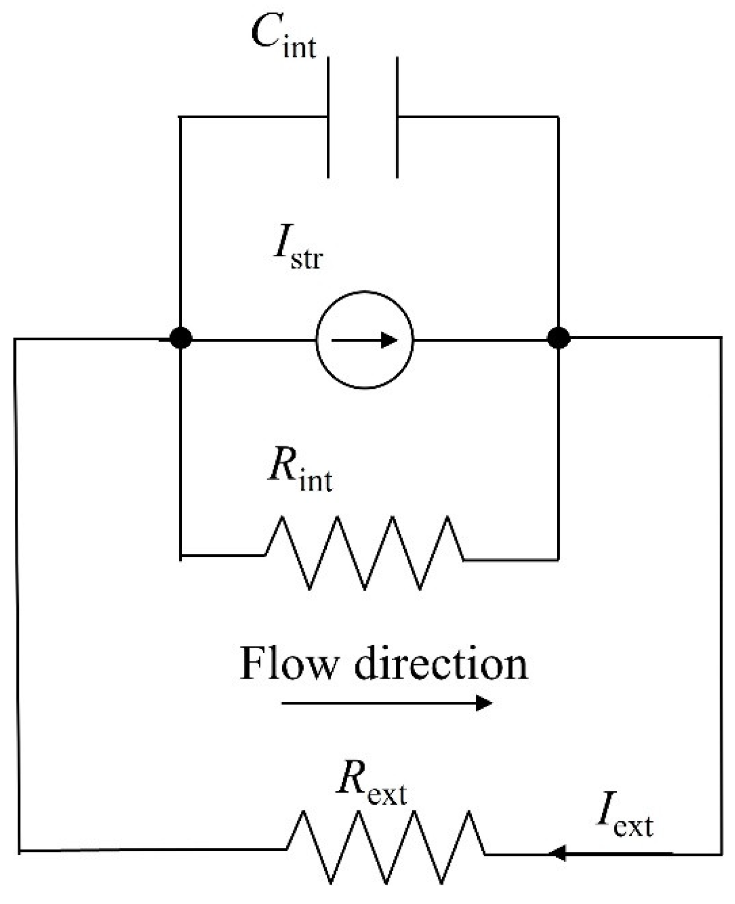
Figure 2.
SEM Image of Wood Structure. SEM image displaying the aligned microchannels in the beech wood sample with an average channel diameter of approximately 50 μm. This microstructure facilitates efficient water evaporation and ion transport, essential for the device’s performance.
Figure 2.
SEM Image of Wood Structure. SEM image displaying the aligned microchannels in the beech wood sample with an average channel diameter of approximately 50 μm. This microstructure facilitates efficient water evaporation and ion transport, essential for the device’s performance.
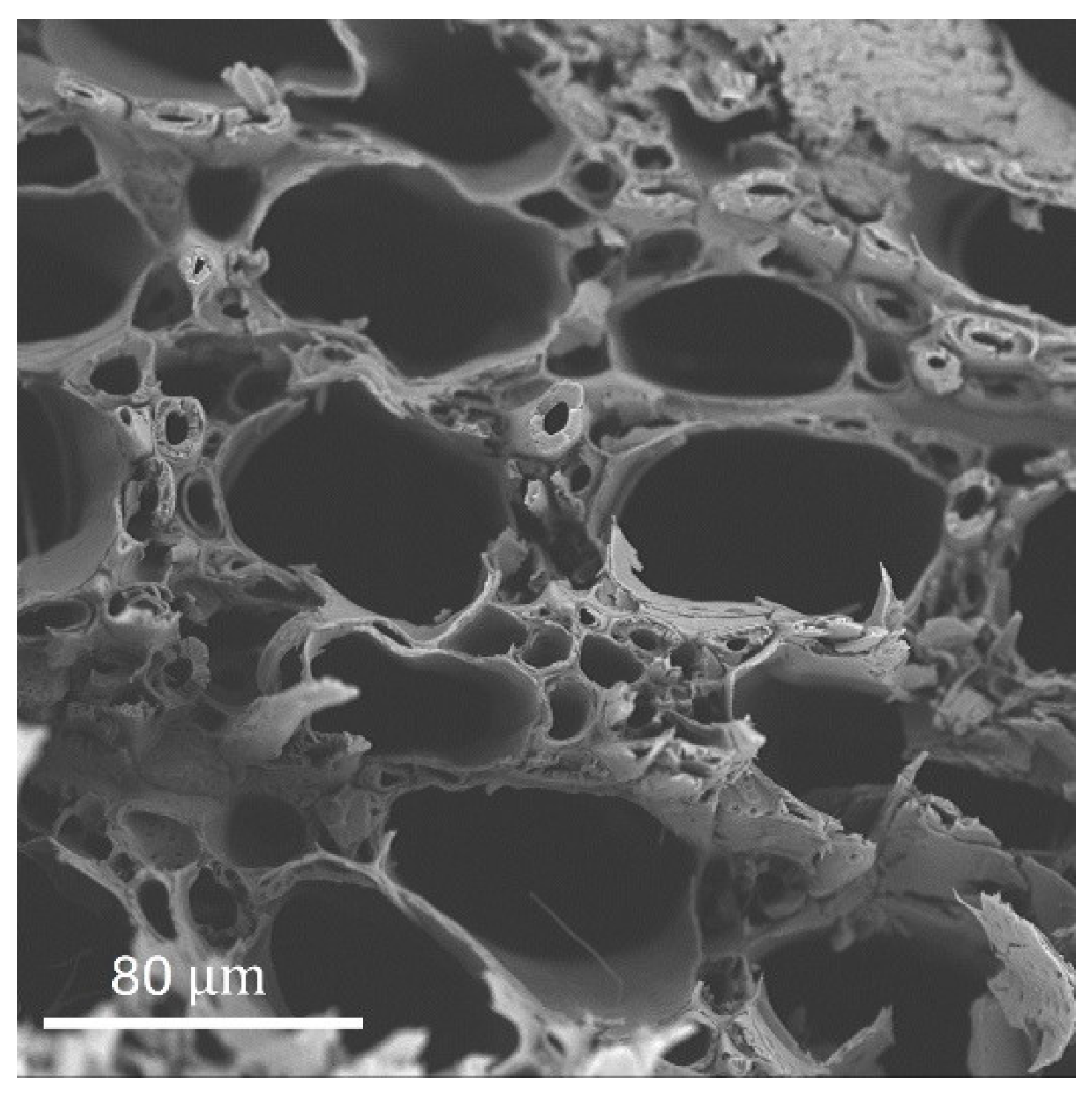
Figure 3.
FTIR spectra of wood after citric acid treatment. FTIR spectra showing characteristic peaks at 1730 () and 1156 (), indicating successful esterification of hydroxyl groups on the wood surface. These modifications enhance the surface charge and hydrophilicity, promoting better ion transport.
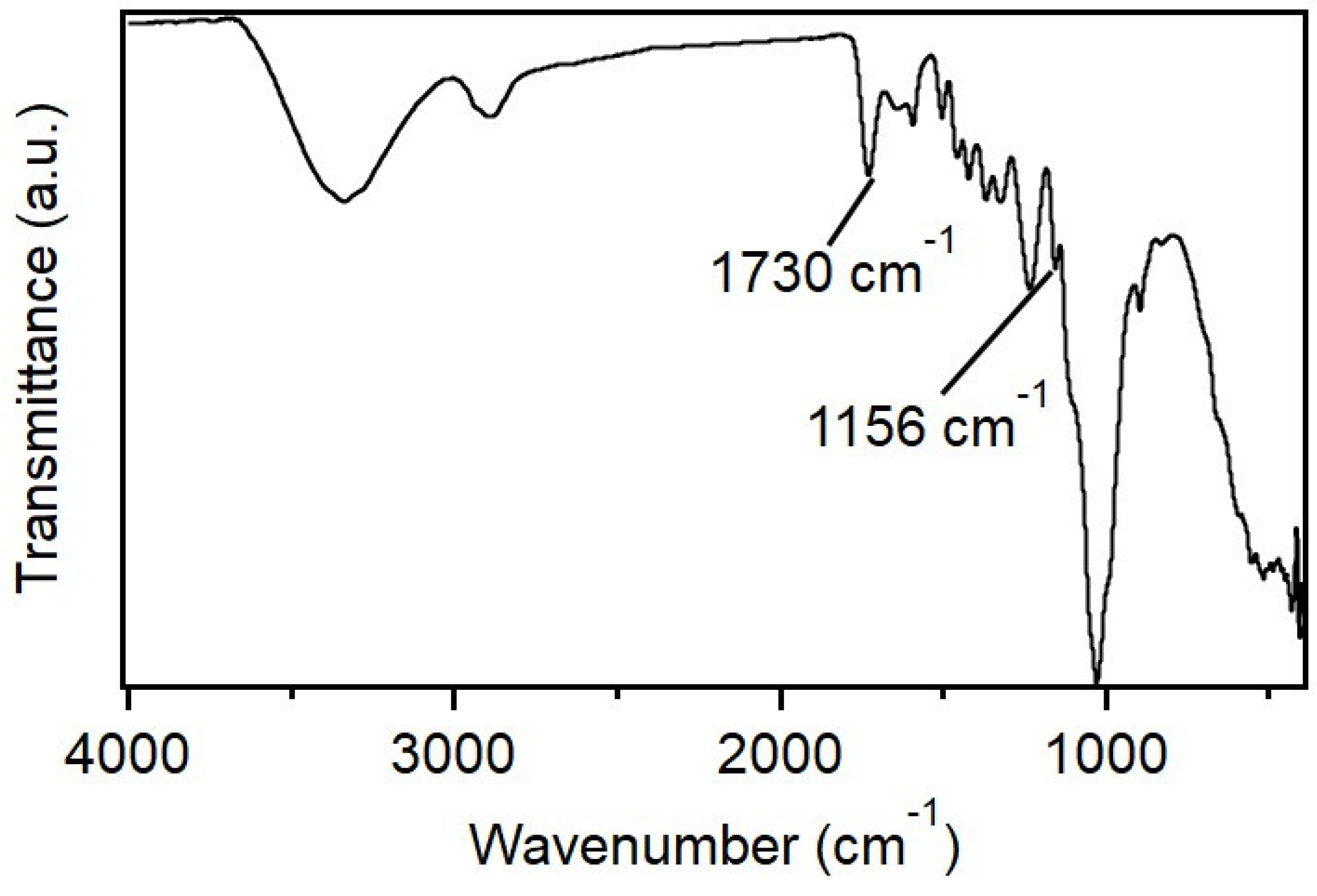
Figure 4.
Contact angle measurement. Contact angle measurement showing hydrophilicity of the CA-treated wood.
Figure 4.
Contact angle measurement. Contact angle measurement showing hydrophilicity of the CA-treated wood.
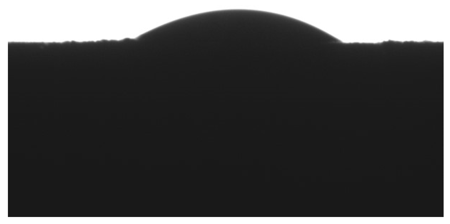
Figure 5.
Zeta potential measurement. Zeta potential measurement of the CA-treated wood, showing a negative surface charge of mV.
Figure 5.
Zeta potential measurement. Zeta potential measurement of the CA-treated wood, showing a negative surface charge of mV.
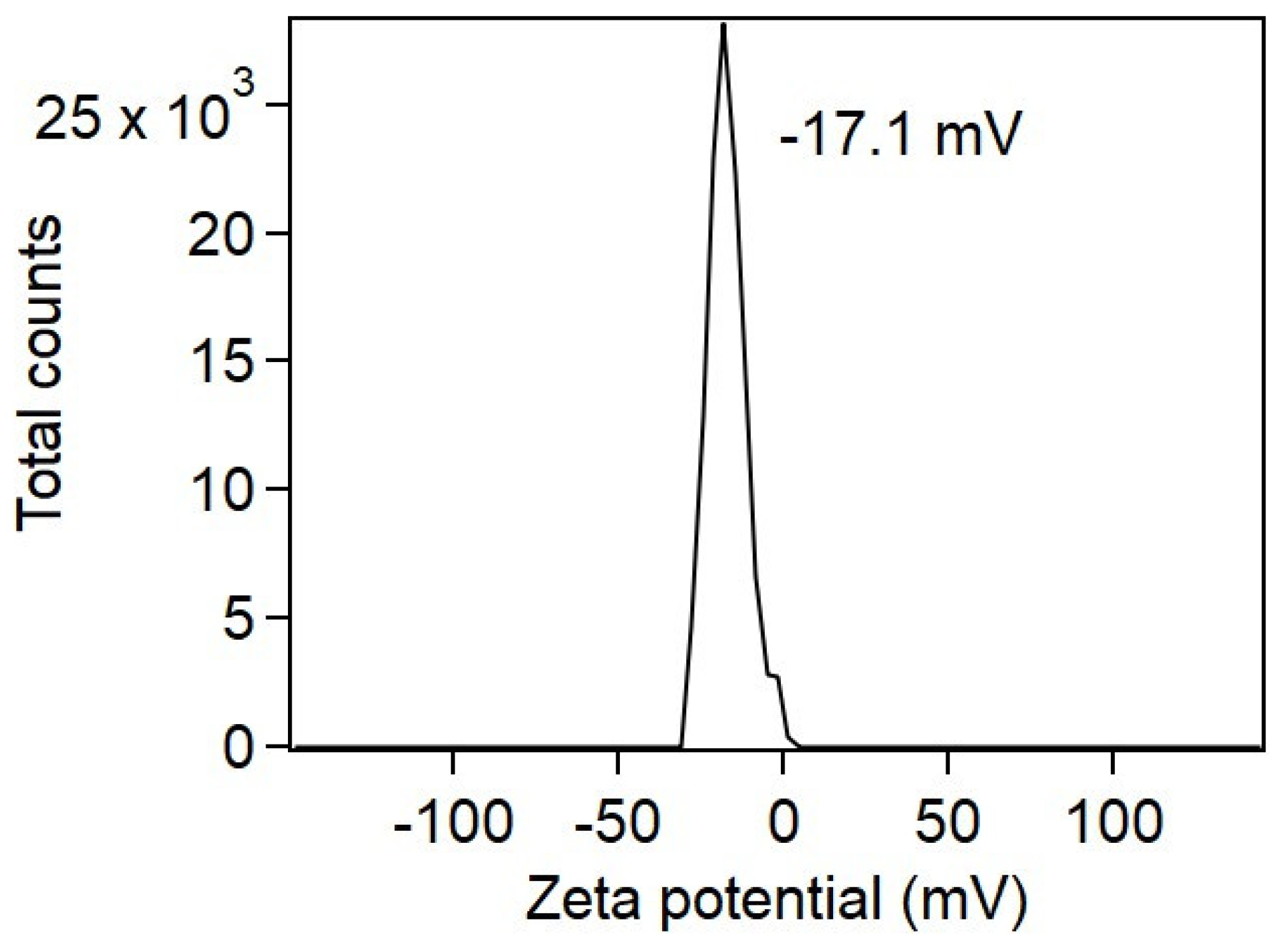
Figure 6.
Device setup of the wood-based nanogenerator. (a) Single device setup for testing current output. (b) Multiple devices series connected and (c) parallel connected to showcase the scale-up setup.
Figure 6.
Device setup of the wood-based nanogenerator. (a) Single device setup for testing current output. (b) Multiple devices series connected and (c) parallel connected to showcase the scale-up setup.
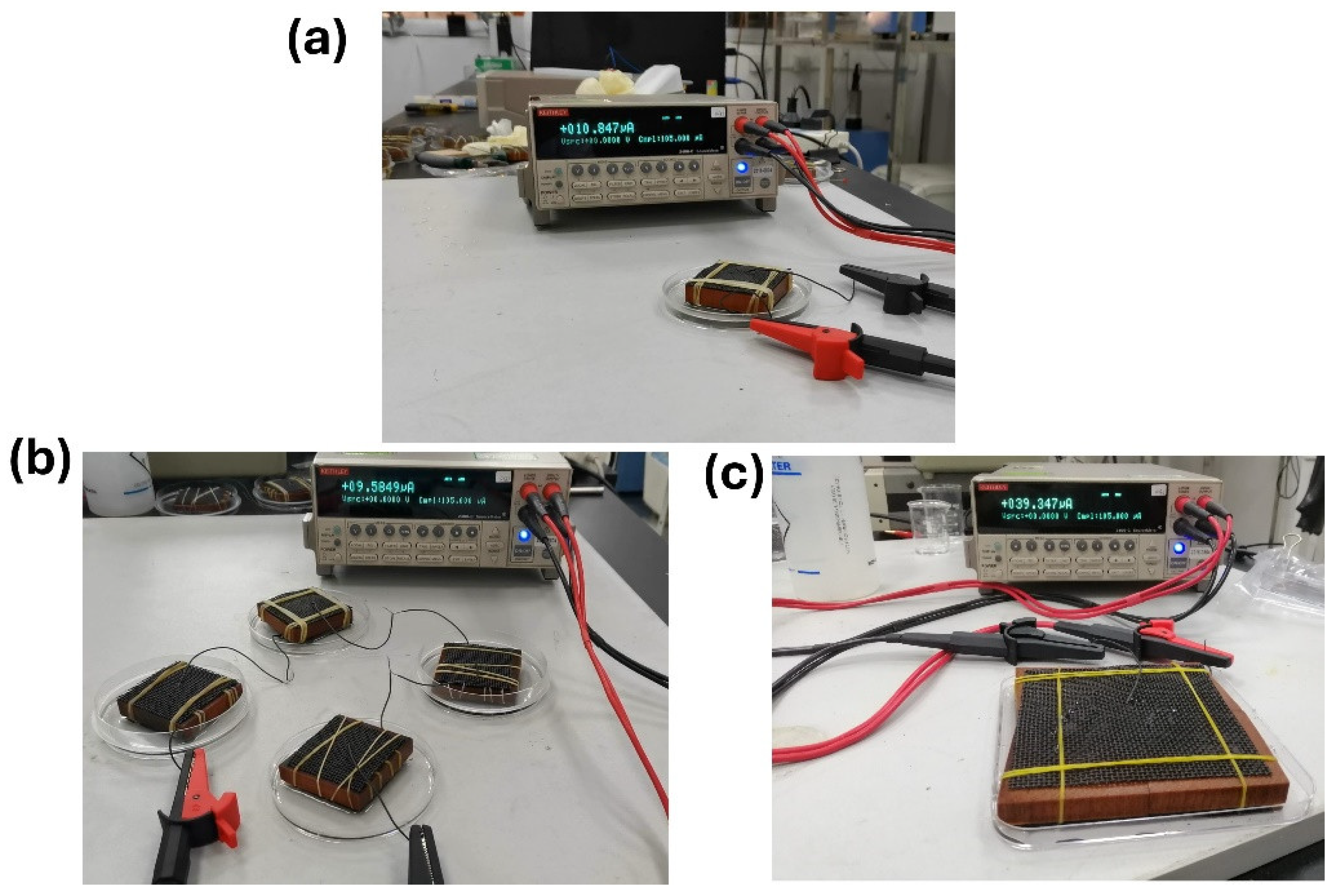
Figure 7.
Short-circuit current vs. time (black) with fitting line (red) using the simplified capacitor-current model.
Figure 7.
Short-circuit current vs. time (black) with fitting line (red) using the simplified capacitor-current model.
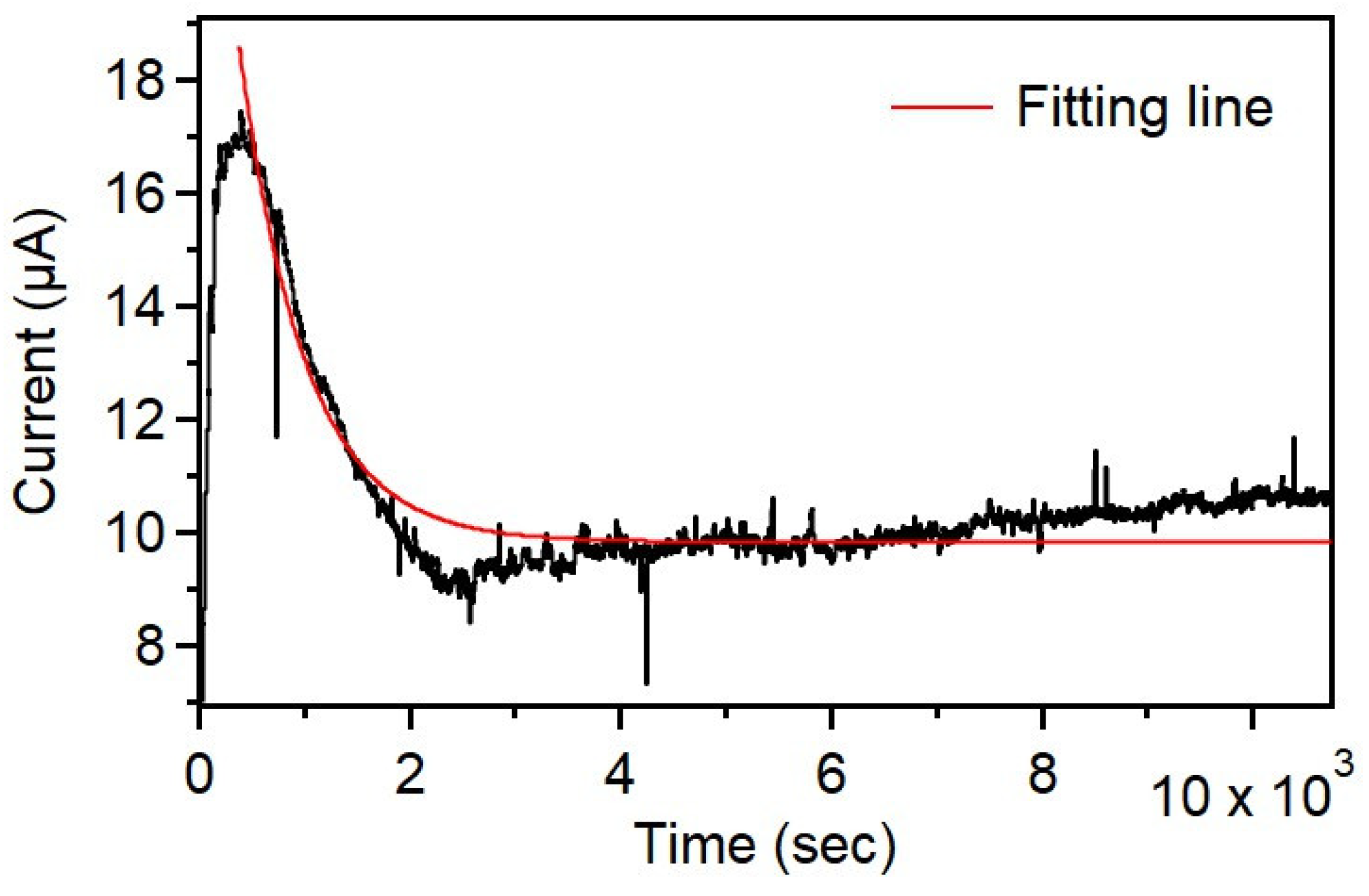

Table 1.
Summary of fitted parameters for the simplified capacitor-current model along with goodness-of-fit measures.
Table 1.
Summary of fitted parameters for the simplified capacitor-current model along with goodness-of-fit measures.
| Parameter | Value | Standard Error | Description |
|---|---|---|---|
| 9.832 μA | ± 0.003 μA | Steady-state current | |
| 16.168 μA | ± 0.044 μA | Initial current peak amplitude | |
| 621.395 s | ± 1.620 s | Time constant | |
| Reduced Chi-Square | 0.293 | — | Goodness of fit measure |
| 0.934 | — | Coefficient of determination | |
| Adjusted | 0.934 | — | Adjusted coefficient of determination |
Disclaimer/Publisher’s Note: The statements, opinions and data contained in all publications are solely those of the individual author(s) and contributor(s) and not of MDPI and/or the editor(s). MDPI and/or the editor(s) disclaim responsibility for any injury to people or property resulting from any ideas, methods, instructions or products referred to in the content. |
© 2024 by the authors. Licensee MDPI, Basel, Switzerland. This article is an open access article distributed under the terms and conditions of the Creative Commons Attribution (CC BY) license (http://creativecommons.org/licenses/by/4.0/).
Copyright: This open access article is published under a Creative Commons CC BY 4.0 license, which permit the free download, distribution, and reuse, provided that the author and preprint are cited in any reuse.


