Submitted:
07 November 2024
Posted:
11 November 2024
You are already at the latest version
Abstract
Tractors operate under varying and unpredictable conditions, making energy management strategies insufficient for maintaining system power dynamics, which often leads to reduced traction power and overall efficiency. To overcome this challenge, a fuzzy-following energy management strategy was developed. This approach utilizes fuzzy control based on energy following to optimize the tractor’s energy output, ensuring more stable power delivery. A target tractor model was constructed using CRUISE, and joint simulations were carried out via the CRUISE-Simulink interface. The results demonstrated that the fuzzy-following strategy stabilized the battery’s state of charge (SoC) and improved fuel economy. The strategy was implemented for controlling a hybrid tractor, and its effectiveness and stability were validated through drivetrain system tests and real vehicle trials under light load, plowing, and power harrowing conditions, successfully achieving power balance under these diverse operating scenarios. Comparative tests between the hybrid tractor using the fuzzy-following strategy and a powershift tractor revealed that the hybrid tractor exhibited superior plowing efficiency and fuel economy under plowing and power-harrowing conditions.
Keywords:
hybrid tractor
; fuzzy-following strategy
; experimental verification
1. Introduction
New energy and hybrid drive technologies have been utilized in the automotive industry for several years, leading to the development of a comprehensive new energy industry chain in China. These technologies are now being progressively adopted in off-road vehicles, such as construction and mining machinery. In the tractor industry, global manufacturers, such as John Deere and Fendt have introduced fully electric tractors at trade shows. In China, institutions, such as the National Intelligent Agricultural Machinery Innovation Center have launched pure electric tractors. However, the performance of pure electric tractors is limited by the capacity of high-voltage battery packs, preventing them from meeting the energy demands of high-load, continuous field operations. Hybrid tractors, which combine a diesel engine and a battery pack as dual power sources, can fulfill the energy requirements for high-load, prolonged fieldwork. By employing a well-designed energy management strategy, hybrid tractors can significantly reduce energy consumption and enhance fuel efficiency.
The energy management strategy is crucial for the performance of series hybrid tractors. Studies[1,2,3] have explored various control strategies for series hybrid tractors, with simulation analyses showing positive outcomes. Researchers in [4,5,6,7] proposed design theories for electric and hybrid tractors, constructing CRUISE models to evaluate vehicle performance and validating parameter design theories. Additionally, research in [8,9,10,11] focused on the design of control systems for a series of hybrid tractors and proposed testing and evaluation methods. Although there has been substantial progress in the development of energy control strategies for hybrid tractors. Most of the studies are limited to simulation analysis, lacking real-world to support their findings. Furthermore, some energy management strategies that rely on complex algorithms are challenging to implement in real-time during operations, which is necessary for practical operations.
In this paper, an energy management strategy based on fuzzy following was developed as part of an actual project. Its feasibility was initially validated through joint simulations using Simulink and CRUISE. The Simulink model was subsequently converted to C code and implmented in the controller of a 220-horsepower (hp) hybrid tractor powertrain. The strategy’s effectiveness was confirmed through powertrain bench tests and field trials. Continuous optimization was performed based on feedback from field operations, ultimately resulting in a reliable energy management strategy for hybrid tractors.
2. Energy Management Strategy Development
2.1. Tractor System Architecture and Drivetrain Parameter Design
In China, high-power heavy-duty tractors are mainly used for plowing, power harrowing, or combined operations involving both traction and harrowing. Traction capability is a key performance metric for tractors. Figure 1 illustrates the traction output and engine power of a 220-hp diesel tractor during plowing. For hybrid tractors to deliver equivalent traction and power output characteristics, their powertrain design and parameters must be tailored to meet these performance requirements.
After evaluating various hybrid powertrain architectures, the hybrid powertrain structure shown in Figure 2 was selected. The generator set, consisting of an engine and generator, functions as the primary energy source, supplying power to the tractor's electric drive system. The power battery system acts as a supplementary energy source, enhancing the drive system’s transient response and providing power feedback. The diesel engine directly drives the PTO.
As depicted in Figure 1, the average traction force of 220 hp during plowing is approximately 45 kN. Given an average plowing speed of 10 km/h, the tractor's tractive power is roughly 127 kW. Factoring in a 10% slip loss and a transmission efficiency of 95%, the hybrid tractor’s drive motor power requirement is calculated to be 147 kW. Therefore, selecting a motor with a rated power of around 150 kW is sufficient to meet the driving power demands of the 220-hp tractor.
The generator must be capable of supporting the motor’s rated power while considering the operating efficiency of both the generator and motor. The generator’s rated power, P_gen, is determined by the following formula:
where P_motor is set at 147 kW, and η_motor and η_gen are both set at 0.95. This results in a generator rated power of 162 kW. A diesel engine with a rated power of 162 kW can be selected to fulfill the PTO output requirements. The other parameters for the hybrid tractor’s powertrain are detailed in Table 1.
P_gen = P_motor/η_motor /η_gen
2.2. Energy Management Strategy
The tractor developed in this project employs a typical series hybrid architecture. Unlike automobiles, hybrid tractors are equipped with relatively small battery packs that cannot sustain continuous power output for extended periods under high loads. Additionally, the operational demands of tractors differ significantly from those of automobiles, which require short bursts of power for acceleration and hill climbing. In contrast, tractors must operate under full load for prolonged durations. As a result, the hybrid power strategies detailed in [16,17] are unsuitable for tractor applications. Hybrid tractors and series or range extender hybrid vehicles thus necessitate distinct energy management strategies.
The core concept of the energy management strategy for hybrid tractors is to maintain the battery pack’s state of charge (SoC) within a specified range of charging and discharging it at low currents during operation, which enhances battery longevity. A balance between the power generated by the generator and the power required by the drive motor is maintained, with the battery pack supplying power to manage transient load fluctuations and ensure a dynamic power output.
The energy management control system for the hybrid tractor employs a fuzzy-following strategy. In this approach, the generator’s power output adjusts in response to changes in the motor’s power demands. The battery pack serves as an auxiliary power source, compensating for power deficits or absorbing excess energy from the generator, while also providing feedback to the motor. The generator’s output is determined based on the operating conditions of both the drive motor and the battery pack, and fuzzy control is applied to optimize power management.
During towing operations, the maximum available power for the drive motor is expressed as:
where Pmotor is the drive motor’s available power, PGen is the generator’s current power output, and PBat represents the permissible discharge power of the battery pack. The latter serves as a power reserve to regulate the tractor’s power output when encountering sudden load changes.
P_motor= P_Gen+ P_Bat
The generator’s power output is given by:
where PGen is the power required from the generator, Pmotor is the motor’s drive power, and PBat is the battery pack’s required charging power, which is non-zero when the SoC falls below a set threshold and zero when above the threshold. P_compensation represents the compensation power, calculated on the battery pack’s SoC and current.
P_Gen=P_motor + P_Bat+P_compensation
Power compensation is managed using fuzzy control, which generates control variables through fuzzy logic and reasoning[19,20]. Fuzzy control is particularly well-suited to scenarios where an exact mathematical model is unavailable, due to its robustness and ease of construction[21,22]. To facilitate code generation and execution within a microcontroller, simple triangular or trapezoidal functions were used as the membership functions.
The power compensation range was set between –10 and 10 kW, and processed through fuzzy logic to determine the power compensation membership function. The high-voltage battery pack current range was set from –20 to 20 A, with out-of-range values capped at boundary limits. The range of the battery pack SoC was [0,100]%. Figure 3, Figure 4 and Figure 5 show the membership functions for power compensation, battery current, and SoC after fuzzy processing, respectively. Based on these membership values, fuzzy rules were established and summarized in Table 2.
The fuzzy inference was processed using the MAX-MIN method, and the final power compensation value was calculated using the centroid defuzzication method. This optimized the battery pack’s charging and discharging performance. The final value for PGen was used to control the generation’s output, powering the tractor’s electric drive system.
3. Simulation and Experimental Study
3.1. CRUISE Vehicle Modeling
CRUISE is primarily designed to simulate the forward performance of vehicles under various driving conditions [11,12,13]. It employs a flexible modular modeling approach [14,15], allowing for a rapid establishment of vehicle models with diverse drivetrain configurations. Based on the system architecture and specification of the hybrid tractor, the individual components were selected within the CRUISE software. The powertrain and high-voltage electrical systems were interconnected through mechanical and electrical connections to create a comprehensive vehicle powertrain model. Figure 6 illustrates the simulation platform for the series hybrid tractor.
3.2. Definition of Simulation Test Operating Conditions and Result Analysis
Series hybrid tractors must maintain a power balance between power generation and propulsion to prevent overcharging or excessive discharging of the power battery pack. This study primarily focused on heavy load driving conditions in the field, to assess whether the control strategy can effectively achieve power balancing during such operations.
Plowing is one of the most common and demanding tasks for tractors; thus, it was selected as the operational condition for the simulation calculations. The empirical formula for determining the traction force required for plowing is:
where z represents the number of plowshares, b1 is the width of a single plowshare (in cm), hk denotes the depth of tillage (in cm), and k is the soil-specific resistance (in N/cm2).
FT = z × b1 × hk × k (N)
For 220-hp farming tractors, a 5-share plow is commonly utilized. Using a single plowshare width of 40 cm, a typical plowing depth of 30 cm, and a soil-specific resistance of 8 N/cm2, the plowing resistance calculated using the formula yields 45,000 N. This resistance was employed as the driving resistance for the 220-hp hybrid tractor during plowing.
The vehicle traction model in CRUISE was configured to operate in a vehicle-independent function mode using the equation:
Fb = 45000 + 0.46*V2 (N)
This equation represents a velocity-dependent second-order resistance model. The simulation of the tractor’s plowing condition was executed using this resistance model.
Within CRUISE, the plowing condition was established, incorporating a cyclic running condition designated as “Farming”. Typically, tractors operate at speeds of 8–10 km/h while plowing; therefore, the maximum operating speed was set to 10 km/h with a permissible speed error of ±1 km/h. The duration of a single cycle was set at 300 seconds, with a corresponding running distance of approximately 900 meters for one plowing operation.
The initial battery level was established at 60%, and operation termination conditions were defined at a low battery level of 20% to prevent potential malfunctions in the energy management strategy due to continued operation at low SoC, as well as considering the maximum capacity of the engine’s fuel tank. The SoC at which the power battery pack begins charging was set at 40%, and charging ceases at 80%. Simulations were conducted using both the fuzzy-following strategy and the energy-following strategy. The evaluation of the fuzzy-following control strategy’s impact on the battery system and fuel economy was conducted through analysis of the SoC, fuel consumption, and current curves. Relevant operational results were obtained from simulation calculations performed in CRUISE.
By simulating and comparing the battery SoC and fuel consumption under the fuzzy-following strategy versus the energy-following strategy, the economic benefits and battery longevity of the tractor under different energy management strategies were assessed. Under the fuzzy-following strategy, the battery pack’s SoC declined at a slower rate due to compensation based on the battery pack’s current and SOC. This alignment kept the average current drawn from the battery pack closer to the target value, resulting in fewer charge and discharge cycles, thus effectively extending the battery pack’s service life. Furthermore, with identical fuel consumption of 420 L, the tractor using the fuzzy-following strategy was able to operate for approximately 1200 seconds longer than under the energy-following strategy, representing a nearly 5% improvement in the economy, which is shown in Figure 7.
The comparison of the current curves, which is shown in Figure 8, indicated that the fuzzy-following strategy effectively minimized both the char ging and discharging currents of the battery. Particularly when the load remained stable, the output current from the battery system approached 0 A, aligning with the vehicle’s energy control objectives. The reduction in current not only decreases heat generation but also enhances the longevity of the battery system.
Figure 9 illustrates the speed, power, and efficiency of the electric motor over three cycles during the simulation. At maximum plowing speed, the electric motor operated at approximately 3200 rpm, achieving a peak efficiency of 95.63%. It functioned within the high-efficiency range of the electric drive system, delivering around 135 kW of power. During acceleration from a standstill, the electric motor could produce up to 145 kW. Selecting an electric motor with a rated power of 150 kW could adequately support this acceleration phase. In steady-state conditions, the electric motor maintained a power reserve of about 10% to counter sudden increases in external resistance and sustain speed. Under plowing conditions, the electric motor operated within its most efficient range, thereby minimizing energy loss and enhancing the tractor's overall economy during plowing tasks.
Figure 10 presents the speed, power, and efficiency curves of the generator across three cycles, highlighting changes before and after the battery charging power was integrated during the simulation. When the battery's SoC fell below 40%, charging power was allocated to the generator as part of the energy management strategy, leading to an increase in the battery’s SoC. The generator maintained an operational speed of around 2000 rpm throughout the simulation, achieving an efficiency of approximately 95% during stable operations, which is indicative of a high-efficiency range. During vehicle acceleration, the generator’s maximum power output reached 151 kW, which increased to 159 kW after incorporating the battery charging power. The chosen generator met the tractor’s power demands even under extreme operating conditions. The energy management strategy effectively regulated the battery pack, the generator’s speed, and the electric motor, aligning with design expectations and maintaining relatively high power generation efficiency.
3.3. Hybrid Powertrain Bench Test
We integrated the energy management strategy model with other vehicle control modules, converting them into the vehicle controller’s software and generating code using TargetLink. This code was then integrated with the underlying software and downloaded to the vehicle controller hardware, utilizing the NXP MPC5744p as the master controller. A bench test of the hybrid tractor’s powertrain was conducted to further validate the effectiveness of the energy management strategy and the reliability of the simulation results obtained from the CRUISE software.
Figure 11 illustrates the bench test for the hybrid tractor's powertrain. The traction electric motor served as the power source, replacing the diesel engine, to evaluate the energy management strategy of the powertrain. During the test, CANoe software was used to monitor CAN bus data, allowing for the assessment of the system’s operational status. The resulting curves for drive motor speed, power battery pack current, generator current, and electric motor current are presented in Figure 12.
The curves demonstrate that rapid changes in motor power due to acceleration and deceleration lead to corresponding fluctuations in the power battery pack’s current. The generator was able to quickly respond to these power changes, supplying the necessary current to drive the motor. Any insufficient or excessive was either supplemented or absorbed by the battery pack. The sudden current changes in the battery pack closely aligned with those observed in the CRUISE simulation, with the maximum discharge current not exceeding 25 A and the maximum pulse charging current limited to 20 A. Once the motor reached a steady power output state, the battery pack’s current typically fluctuated by about ±1 A. The energy management strategy implemented during the bench test effectively managed the output states of the motor, generator, and battery pack, aligning with the design objectives and the outcomes of the CRUISE simulation.
3.4. Hybrid Tractor Operation Test
We performed field tests with a hybrid tractor to assess the effectiveness of the fuzzy-following energy management strategy and the reliability of the tractor’s energy management system during heavy-duty traction and PTO operations, specifically in plowing and power-harrowing tasks.
As illustrated in Figure 13, during the plowing operation, when the load was stable, the battery pack experienced a slight discharge, with current levels ranging from 2 to 3 A. Following a sudden drop in the motor load, a pulse charge of 86 A occurred, which the battery pack absorbed. According to the charging parameters of the battery pack, this pulse charging current was below 4C, ensuring that the battery pack’s service life was not adversely affected. The tractor maintained a plowing speed of 9 to 10 km/h, with motor drive power hovering around its maximum output of 150 kW. As the battery pack gradually discharged, the minimum voltage of an individual battery cell dropped to below 3.75 V, resulting in a reduction of approximately 5 kW in drive power. Some of the current produced by the generator was used for battery charging, keeping the charging current within acceptable limits. The speed remained within the high-efficiency range for farming. The energy management strategy effectively controlled the energy flow between the battery pack, generator, and motor during the plowing operation. The primary objectives included maximizing the efficiency of both the motor and generator, managing the SoC of the battery pack, and enhancing the energy utilization efficiency of the hybrid tractor to achieve energy savings.
Figure 14 depicts the operating status during the PTO’s power-harrowing operation. The PTO operated at 540 rpm throughout the task. When the engine load approached 100% of its rated power, the electric motor’s output power decreased, leading to a reduction in the vehicle’s driving speed. However, this did not affect the PTO’s rotational speed, which remained constant at 540 rpm, ensuring its operational effectiveness. During the entire operation, the instantaneous discharge current from the battery pack was kept below 10 A, while the instantaneous charging current did not exceed 20 A. Overall, the charging and discharging levels of the batteries were maintained at a lower threshold, promoting the longevity of the battery pack.
The field tests demonstrated that the energy management strategy successfully facilitated energy distribution and regulation for the battery pack, generator, motor, and PTO across various conditions of heavy-duty traction and PTO operations with specific traction loads. By optimizing energy management parameters, the strategy effectively improved operational efficiency in diverse environments.
3.5. Operation Comparison with Powershift Tractor
The performance of the hybrid tractor can be assessed through comparative testing with a powershift tractor of equivalent hp. By operating both tractors in a standardized field with identical farming implements, characteristics related to power, fuel economy, and work efficiency can be evaluated.
The comparative tests shown in Figure 15 revealed that the plowing efficiency of the hybrid tractor was comparable to that of the powershift tractor with the hybrid exhibiting approximately 20% lower fuel consumption per unit area. In the power harrowing operation, the hybrid tractor demonstrated nearly 14% greater efficiency than the powershift tractor, alongside a reduction of about 14% in fuel consumption per unit area. Overall, the hybrid tractor exhibited clear economic advantages over the powershift tractor.
4. Results
This paper analyzed the traction force and power requirements of high-hp tractors and the drivetrain structure and operating characteristics of hybrid tractors. A fuzzy-following energy management strategy was developed, and a hybrid tractor simulation model was constructed in CRUISE software. By interfacing CRUISE with Simulink, the fuzzy-following strategy is compared with a traditional energy-following strategy. Results showed that the fuzzy-following strategy was 5% more economical and extended the power battery’s service life. Bench tests validated the strategy’s regulation of power balance under light loads, confirming the accuracy of the simulation results. In the field operation tests, the strategy successfully managed energy distribution among the engine, generator, motor, and battery during plowing and harrowing. Performance comparison tests demonstrated that the hybrid tractor showed improvements in operating efficiency and economy over the powershift tractor.
Author Contributions
Conceptualization, X.Z. and G.Z.; methodology, X.Z., G.Z., ML; software, X.Z., Z.X. J.W. and Y.L.; data curation, X.Z., Z.X. J.W. and Y.L.; formal analysis, M.L., J.W. and X.Z.; validation Z.X., Y.L. and J.W.; writing—original draft preparation, X.Z.; writing—review and editing, G.Z. and M.L.; funding acquisition, M.L. All authors have read and agreed to the published version of the manuscript.
Funding
China National Machinery Industry Corporation (SINOMACH) Youth Science and Technology Fund Key Project (QNJJ-ZD-2022-03); State Key Research and Development Program of China (2022YFD2001204).
Data Availability Statement
No new data were created or analyzed in this study. Data sharing is not applicable to this article.
Conflicts of Interest
The authors declare no conflict of interest.
References
- Luo Guangju. Research on Energy Management Strategy of Series Diesel Electric Hybrid Tractor [D]. Master, Nanjing: Nanjing Agricultural University, 2019 (in Chinese).
- Zhou Rundong. Study On Energy Distribution Strategy Of Tandem Hybrid Tractor Under Different Working Conditions [D]. Master, Nanjing: Nanjing Agricultural University. 2020. (in Chinese).
- Fang Shuping, Zhou Zhili, Xu Liyou. Energy management strategies for series hybrid tractors [J]. Journal of Henan University of Science & Technology (Natural Science), 2015,36(3):61-66 (in Chinese). [CrossRef]
- Xu Liyou, Liu Mengnan, Zhou Zhili. Design of drive system for series hybrid electric tractor. Transactions of the Chinese Society of Agricultural Engineering [J], 2014,30(09): 11-18. [CrossRef]
- Liu Mengnan, Xu Liyou, Zhou Zhili, Liu Weiguo. Establishment of Extended Range Electric Tractor and Its Rotary Cultivator’s Simulative Platforms [J]. China Mechanical Engineering, 2016,27(03):413-419 (in Chinese). [CrossRef]
- Liu Mengnan. Study on design theory and control strategy of electric tractor [D]. PhD, Xi'an: Xi'an University of Technology. 2020 (in Chinese). [CrossRef]
- Zhao Jinghui, Xu Liyou, Liu Enze, Liu Mengnan, Meng Tao. Design for Drive System of Extended -range Electric Tractor [J]. Journal of Agricultural Mechanization Research, 2018,40(11): 236-240. (in Chinese). [CrossRef]
- LU Zhixiong, HOU Xinfen, DENG Xiaoting. Matching design and traction tests for driving system of series hybrid electric tractor [J]. Journal of Nanjing Agricultural University, 2017, 40(05): 928-935. (in Chinese). [CrossRef]
- Liu Yanan, Deng Xiaoting, Zhang Wenhan, Zhu Yixuan , He Ruiyin. Design Theory and Method Research on Tandem Hybrid Tractor Drive System [J]. Agricultural Equipment & Vehicle Engineering, 2018,56(02): 49-54. (in Chinese). [CrossRef]
- Hou Xinfen. Design and Performance Analysis on Driving System of Series Hybrid Electric Tractor. [D]. Master, Nanjing, Nanjing Agricultural University. 2017. (in Chinese). [CrossRef]
- Chen Yanni. Study on design and drive control methods of powertrain for electric tractor [D]. PhD, Beijing, China Agricultural University. 2018. (in Chinese).
- Wang Baohua, Luo Yongge. Simulation And Modeling Of Vehicle Based On Cruise Software [J]. Journal of Hubei University of Automotive Technology,2005,19(2):5-8 (in Chinese). [CrossRef]
- Wang Qingnian, Yu Yongtao, Zeng Xiaohua, Yu Yuanbin. Development of forward-looking simulation platform for hybrid electric vehicle based on software cruise [J]. Journal of Jilin University (Engineering and Technology Edition),2009,39(6):1413-1419(in Chinese).
- Zhao Shuiping, Chen Liao, Chi Jingwei, Pan Chaofeng On Energy Management Strategy for Fuel Cell Electric Vehicle(FCEV)Based on Cruise-simulink Co-simulation [J]. Journal of Chongqing Jiaotong University(Natural Sciences),,2011, 30(5):1068-1072. (in Chinese). [CrossRef]
- He Jingwei. Research on control strategy for parallel-series HEV based on cruise [D]. Master, Xi’an: Xi'an University of technology,2016. (in Chinese). [CrossRef]
- Duan Yanbo, Zhang Wugao, Huang Zhen. Technology analysis of hybrid electric vehicles [J], Diesel Engine, 2003 (1): 43-46 (in Chinese). [CrossRef]
- Simona Onori, Lorenzo Serrao, Giorgio Rizzoni, Hybrid electric vehicles energy management strategies[M]. Hu Xiaosong, Tang Xiaolin, Liu Teng, traslator. Beijing: Machinery Industry Press, 2020 (in Chinese).
- Sun Fengchun, He Hongwen. Handbook of electric vehicle. Volume 2, Hybrid electric vehicle design [M] Machinery Industry Press, 2019 (in Chinese).
- Pan Shouchen. A Research on Vehicle Control Strategy of Series-parallel Hybrid Electric Bus [D].Master, Zhengzhou, Zhengzhou University, 2015. (in Chinese).
- Xu Shijing. Optimization Research of Energy Manangement Strategy for Series Hybrid Electric Vehicles [D]. PhD, Tianjin Tianjin University. (in Chinese). [CrossRef]
- Liu Jinkun. Intelligent Control [M]. Beijing: Electronic Industry Press. 2007. (in Chinese).
- Shi Xinmin, Hao Zhengqing. Fuzzy control and its MATLAB simulation (2nd ed.) [M]. Beijing: Tsinghua University Press,2018. (in Chinese).
- Cruise Interface 2015 R2[M]. AVL LIST GmbH, 2015.
- [24 Cruise User Guide 2015 R2[M]. AVL LIST GmbH, 2015.
- Dong Xiangjun. Simulation Research on the hybrid electric bus based on Cruise software [D].Master, Xi’an, Chang’an University, 2014. (in Chinese). [CrossRef]
- Yin Jian. Co-simulation Analysis of Increased Program Pure Electric Bus Based on Cruise and Matlab Software [J]. Bus & Coach Technology and Research, 2012.10:13-15 (in Chinese). [CrossRef]
Figure 1.
Traction force and engine power during plowing operation of the 220-hp tractor.
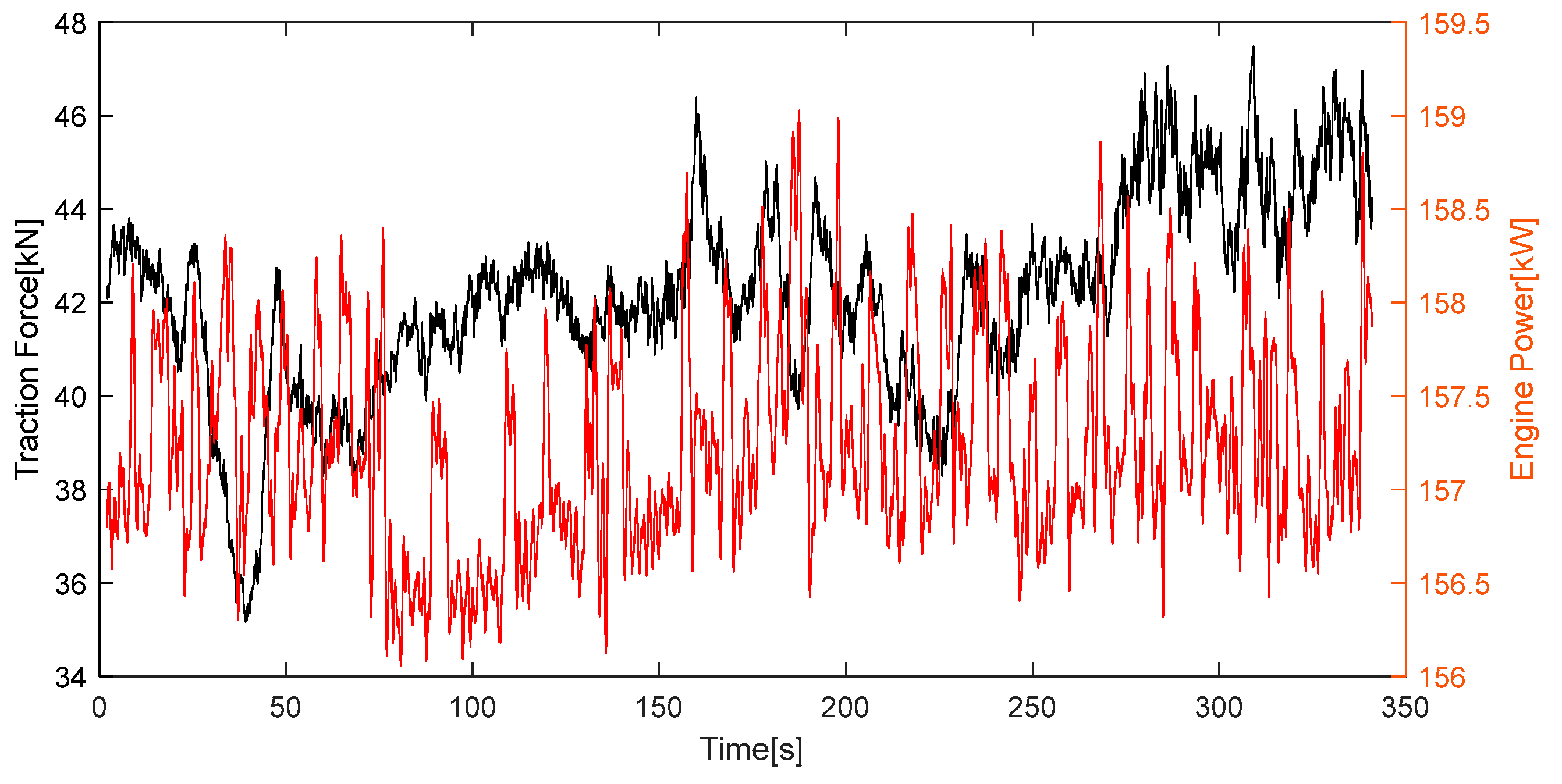
Figure 2.
Powertrain architecture of the hybrid tracto.
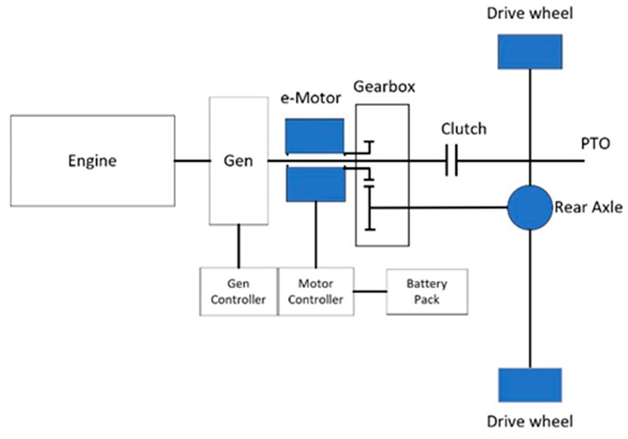
Figure 3.
Membership function of the power compensation.
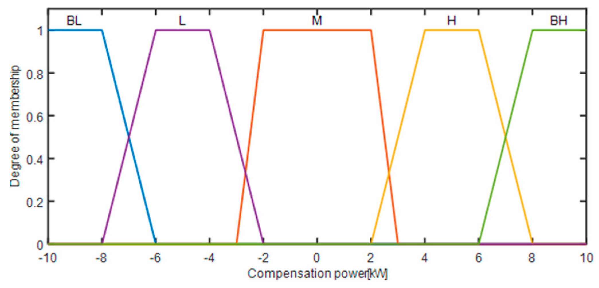
Figure 4.
Membership function of the HV battery current.
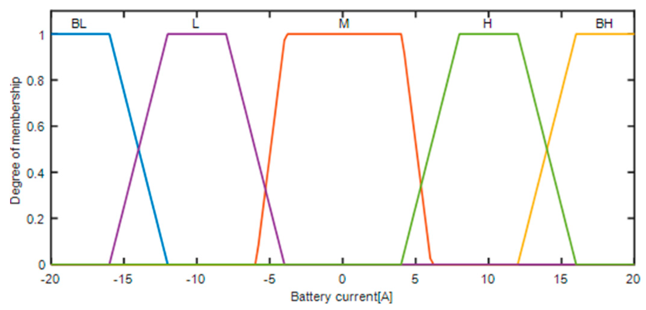
Figure 5.
Membership function of the HV battery SoC.
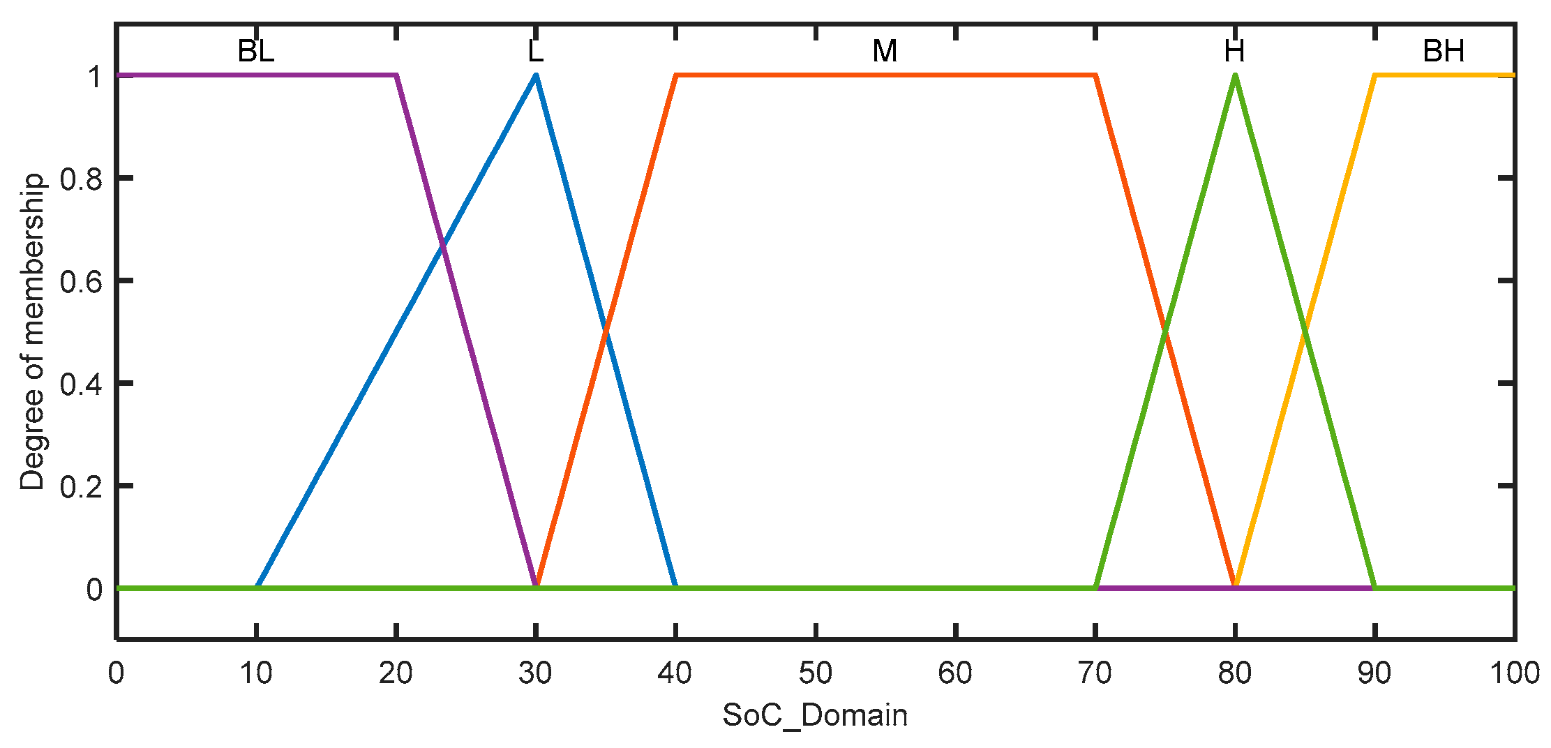
Figure 6.
Hybrid tractor simulation model in CRUISE.
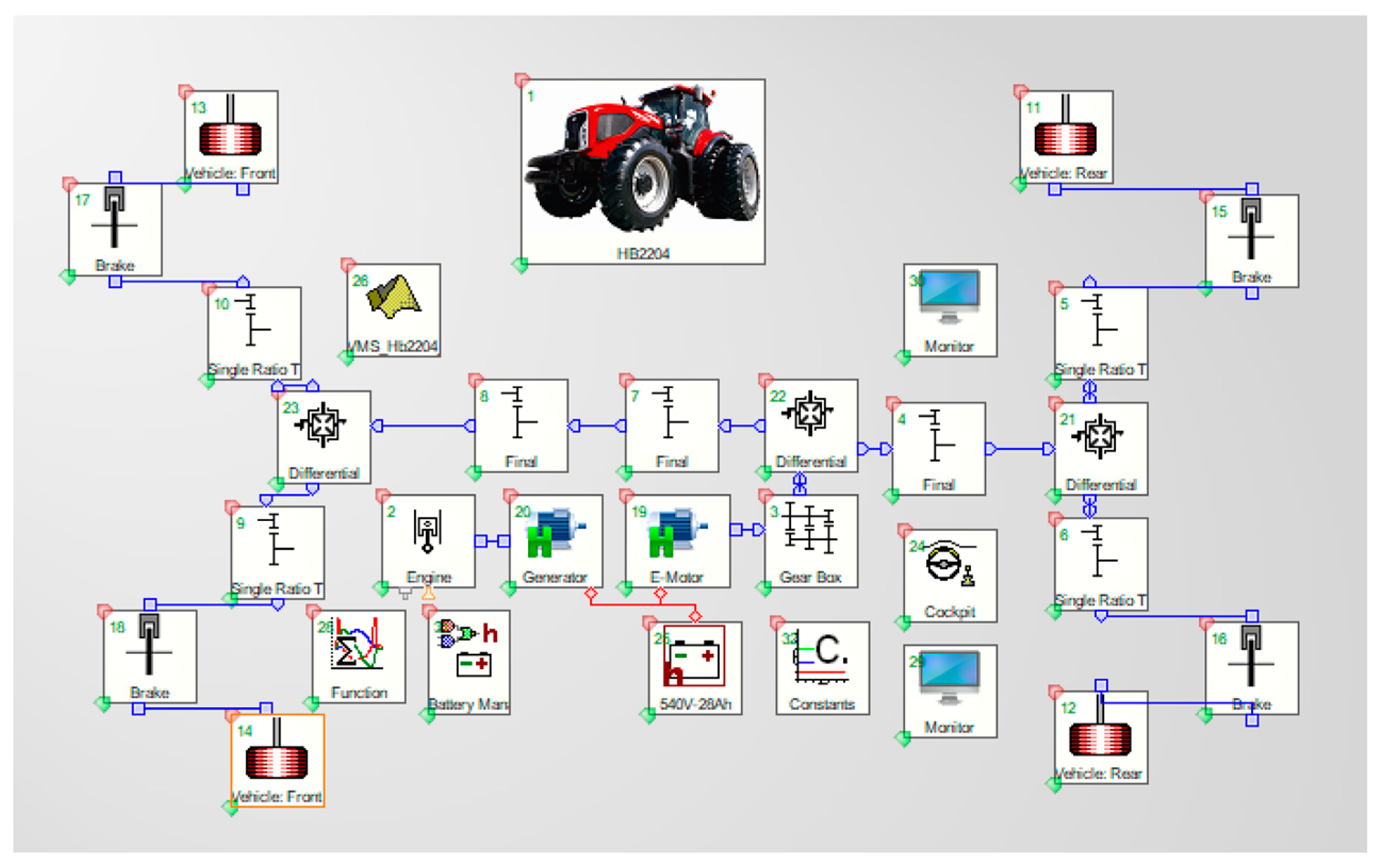
Figure 7.
Fuel consumption and SoC curves during the simulation.
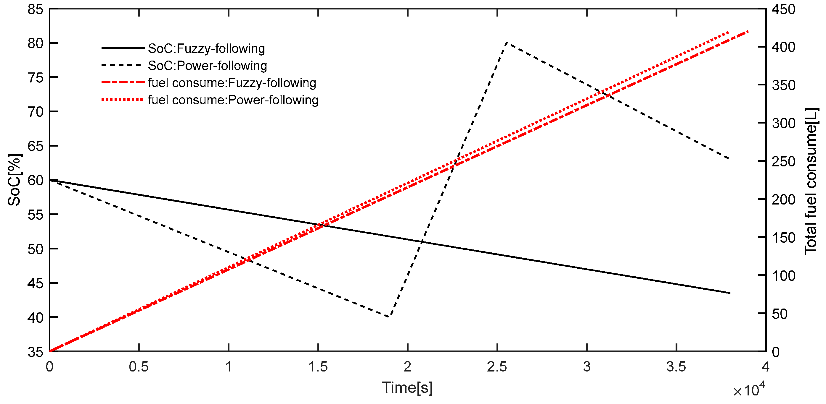
Figure 8.
Battery current curve during the simulation.
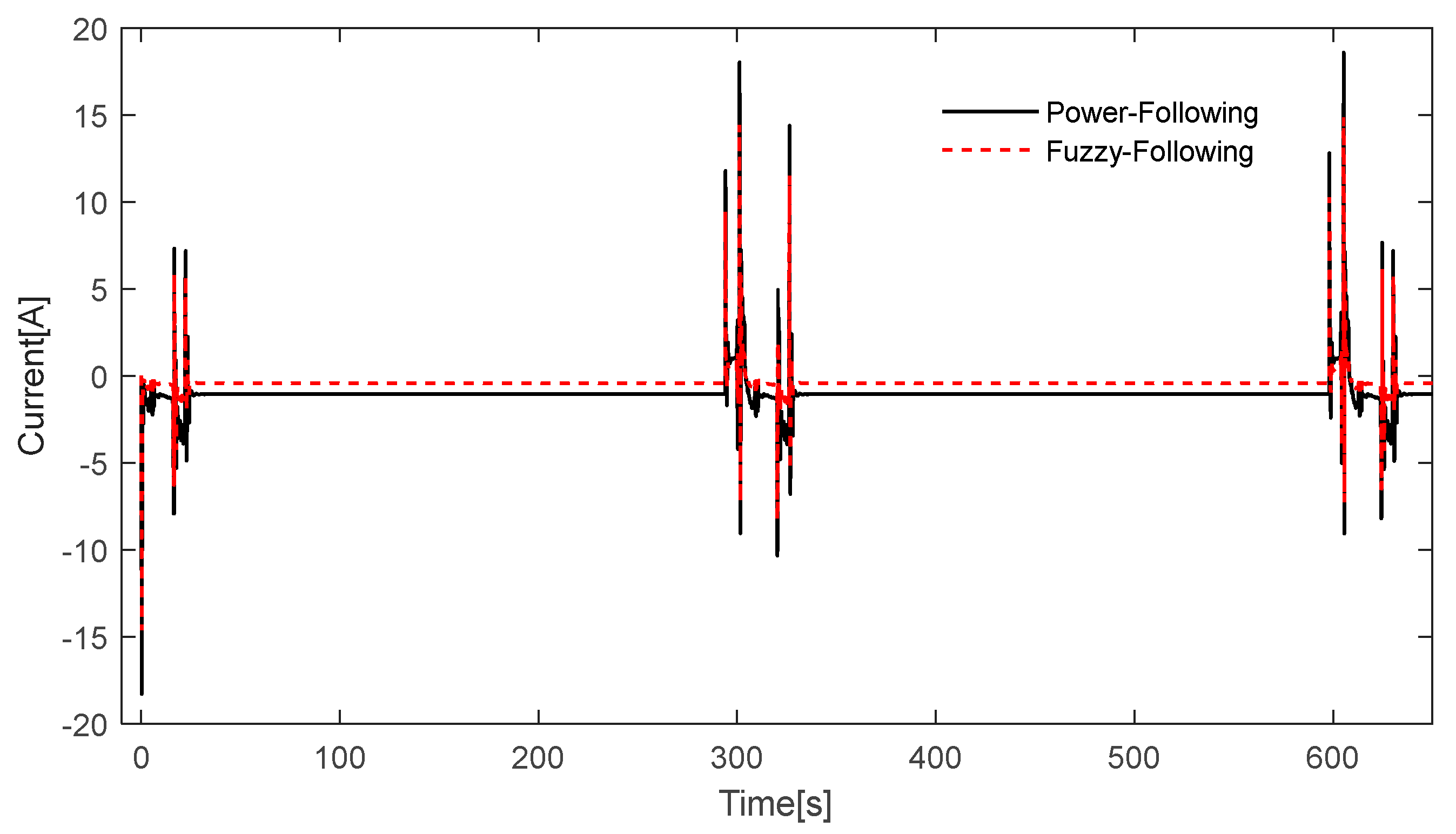
Figure 9.
Motor speed, power, and efficiency curves during the simulation.
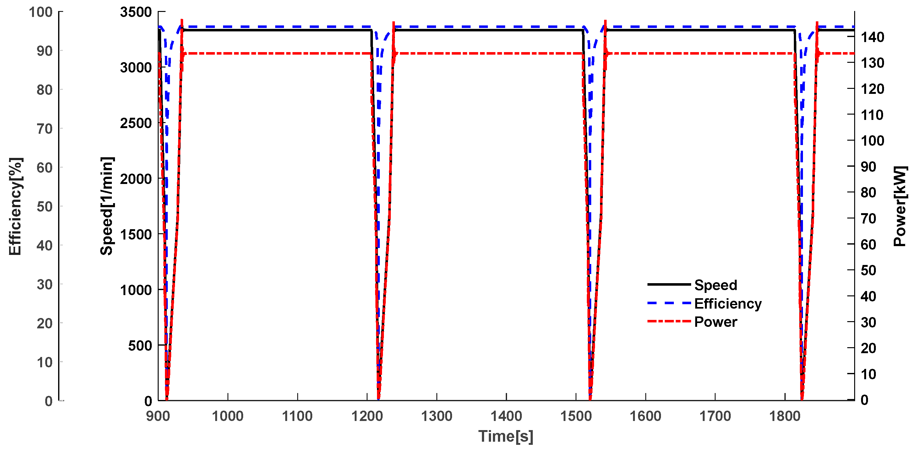
Figure 10.
Generator speed, power, efficiency, and HV battery SoC curves during the simulation.
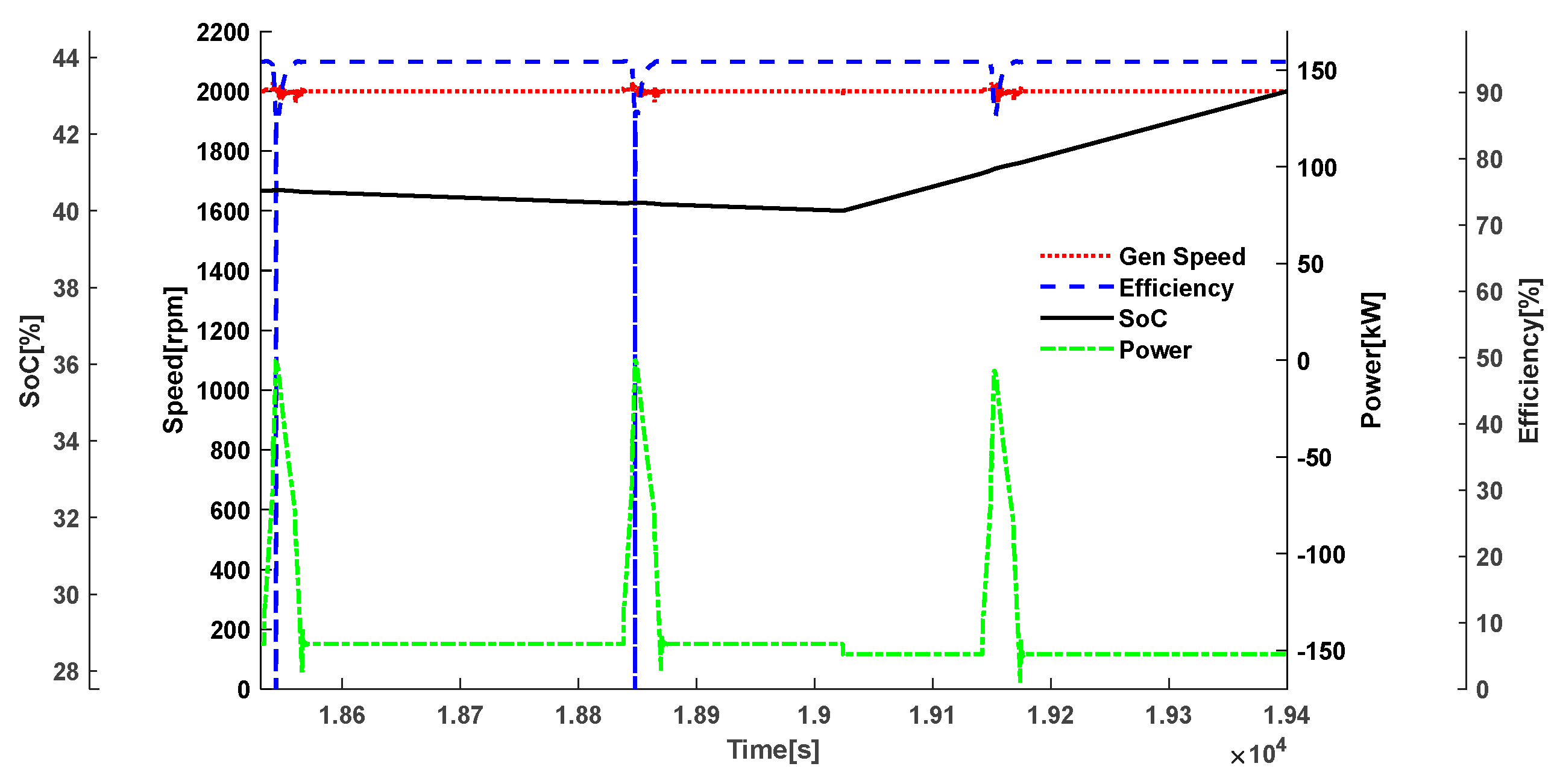
Figure 11.
Bench test of the hybrid powertrain system.
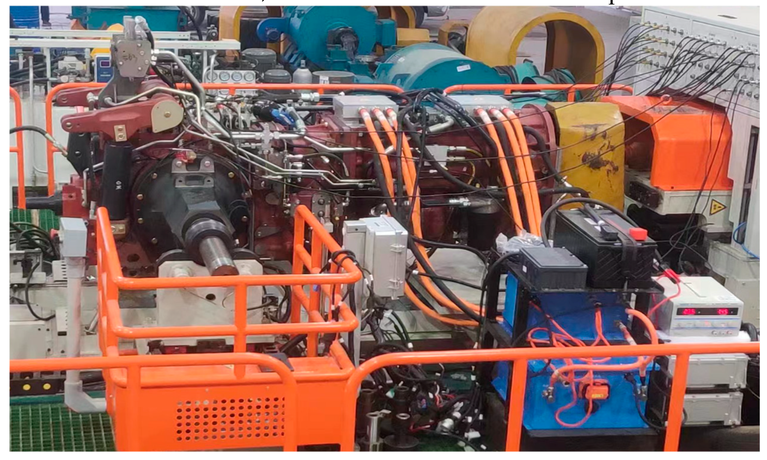
Figure 12.
Motor speed, HV battery current, generator current, and motor current during the bench test.
Figure 12.
Motor speed, HV battery current, generator current, and motor current during the bench test.
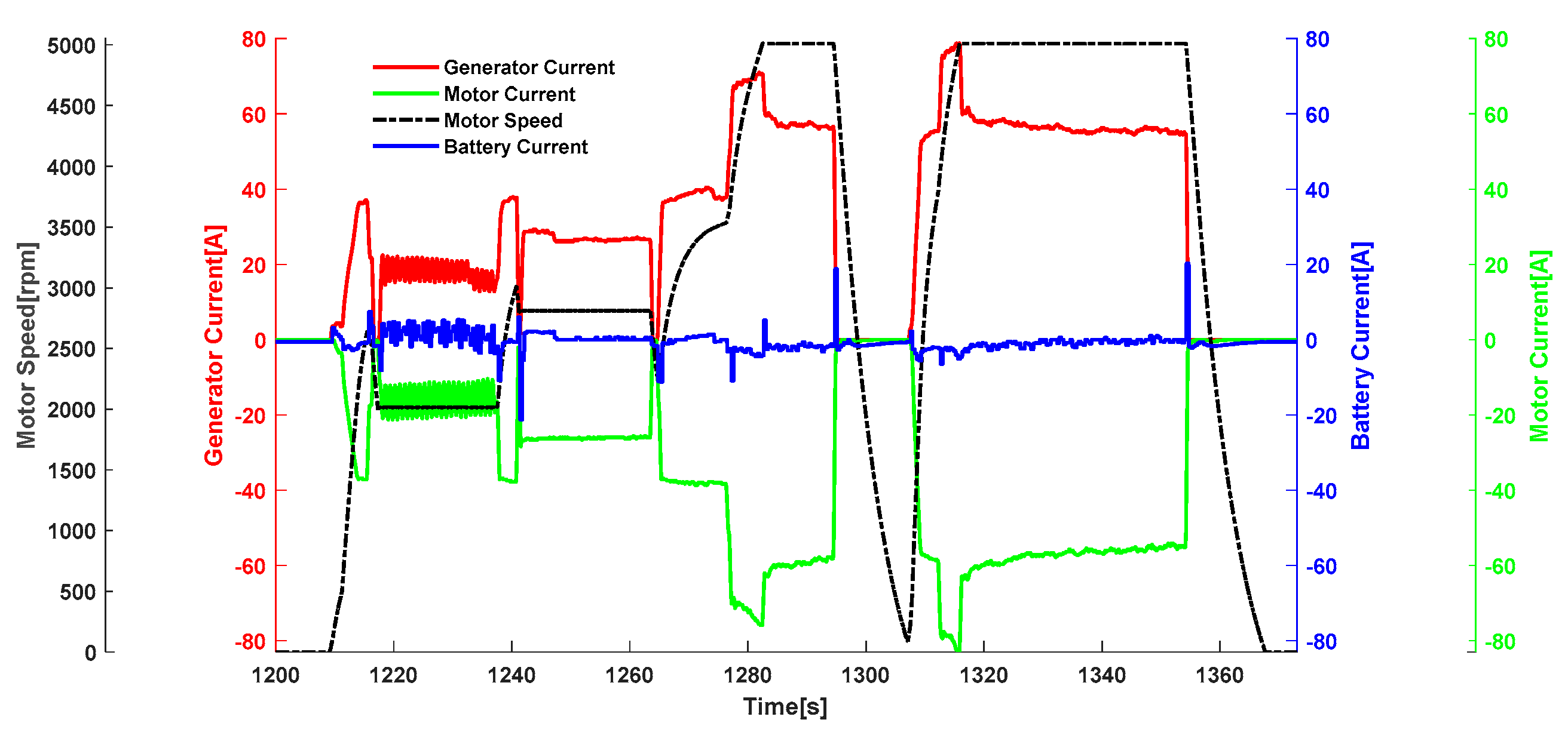
Figure 13.
Motor power, vehicle speed, minimum cell voltage, and HV battery current during the plowing test.
Figure 13.
Motor power, vehicle speed, minimum cell voltage, and HV battery current during the plowing test.
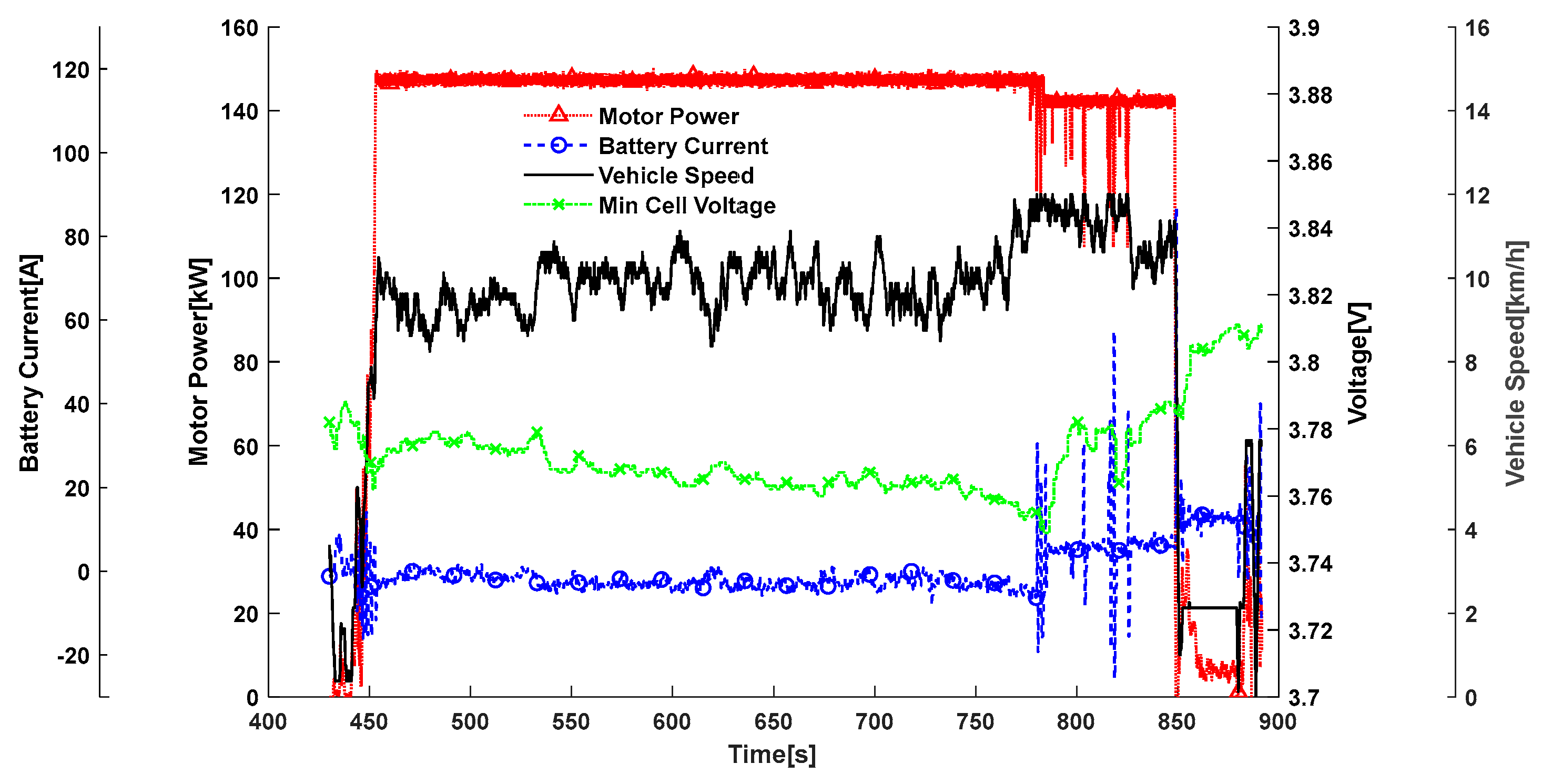
Figure 14.
PTO speed, vehicle speed, engine load, and HV battery current during the PTO test.
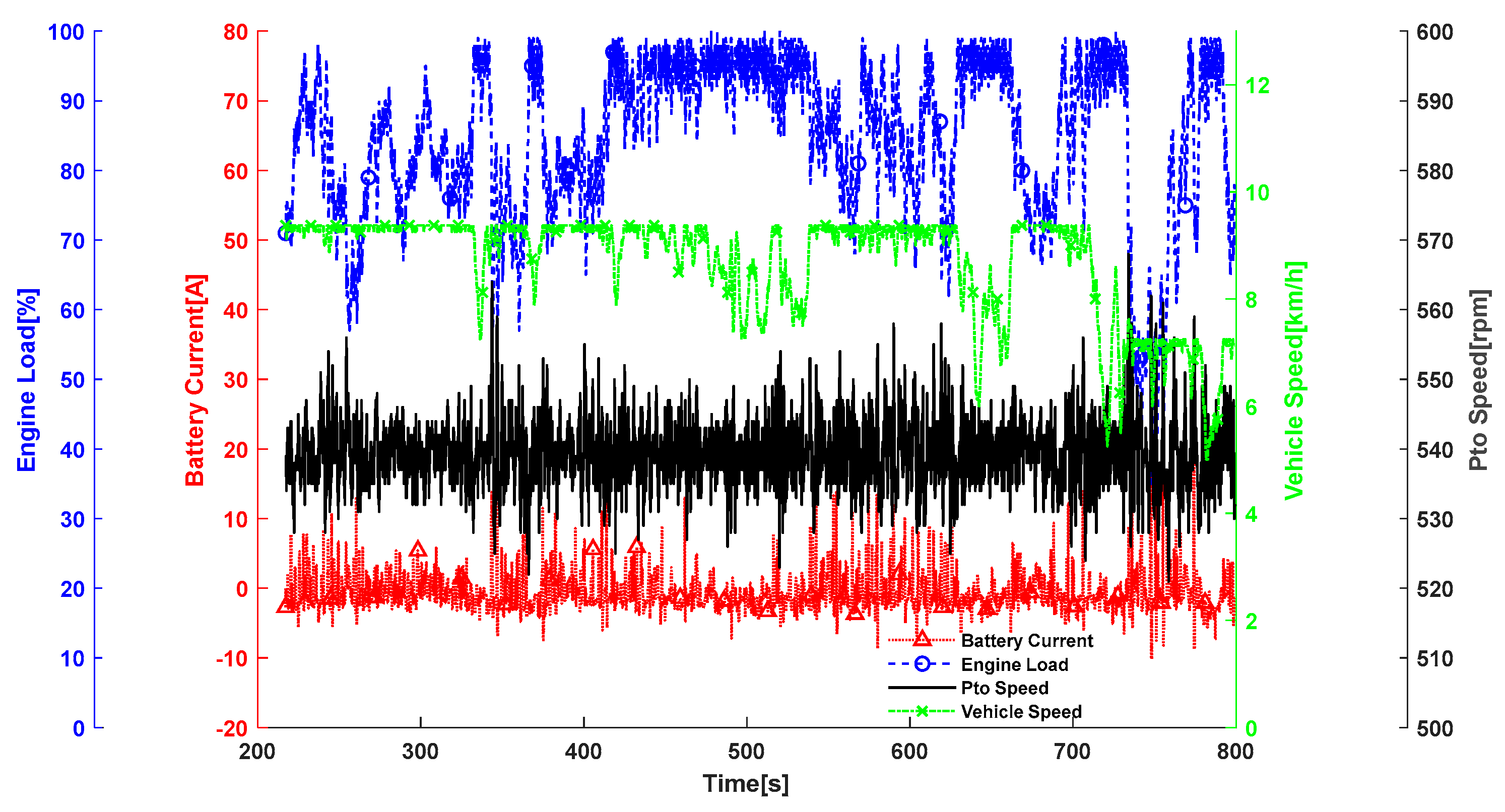
Figure 15.
Operation comparison between the hybrid tractor and the powershift tractor.


Table 1.
Powertrain parameters of the hybrid tractor.
| Item | Parameter | Value |
|---|---|---|
| Diesel Engine | Rated power (RPM) | 162 kW@2000 rpm |
| HV battery pack | Capacity | 13 kWh |
| Rated voltage | 540 V | |
| Drive motor | Power rating | 150 kW |
| Maximum speed | 6000 rpm | |
| Generator | Power rating | 162 kW |
| Maximum speed | 4000 rpm |
Table 2.
The fuzzy control rules of the power compensation.
| Compensated power | Battery pack current | |||||
| BL | L | M | H | BH | ||
| SoC | BL | BH | BH | H | M | M |
| L | BH | H | M | M | M | |
| M | H | M | M | M | M | |
| H | H | M | L | L | L | |
| BH | M | M | BL | L | BL | |
Disclaimer/Publisher’s Note: The statements, opinions and data contained in all publications are solely those of the individual author(s) and contributor(s) and not of MDPI and/or the editor(s). MDPI and/or the editor(s) disclaim responsibility for any injury to people or property resulting from any ideas, methods, instructions or products referred to in the content. |
© 2024 by the authors. Licensee MDPI, Basel, Switzerland. This article is an open access article distributed under the terms and conditions of the Creative Commons Attribution (CC BY) license (http://creativecommons.org/licenses/by/4.0/).
Copyright: This open access article is published under a Creative Commons CC BY 4.0 license, which permit the free download, distribution, and reuse, provided that the author and preprint are cited in any reuse.


