
Submitted:
02 November 2024
Posted:
05 November 2024
You are already at the latest version
Abstract
This study introduces a novel calibration method for accurate external wrench measurement using a 6-axis FT sensor, designed to mimic human-like capabilities in robots. While current approaches for FT sensor calibration often rely on fixed parameters, our method models and calibrates essential parameters: bias, crosstalk, CoM, and inclination, to ensure reliable force measurements in mobile and inclined environments. A mobile manipulator installed with an FT sensor and a gripper is used to demonstrate calibration effectiveness across varying postures and inclined conditions, with non-linear optimization applied to minimize sensor-data errors. The proposed method addresses typical calibration challenges, including the effects of the end tool and base inclined, which are not commonly covered in existing methods. Results show that, on a non-inclined base, crosstalk and CoM calibration reduce average error by approximately 14% and variance by 38%. On an inclined base, our full calibration process reduces mean error by 42% and variance by 65%. These findings highlight the importance of inclined calibration for achieving accurate external force estimations, especially for mobile manipulator applications where the environment changes often.
Keywords:
calibration
; sensors
; crosstalk
; optimization
1. Introduction
Humans possess proprioceptive sensors that enable them to estimate the weight of objects accurately, excluding the weight of their own weight. This sensory ability allows humans to use gravity as a reference to estimate the weight of an object reliably, even when the ground is inclined or their posture changes. Implementing a similar capability in robots requires using FT sensors to estimate the weight of objects based on the gravitational force acting on the sensor. However, because FT sensors utilize multiple strain gauges or capacitance measurements to calculate force and torque, changes in posture or ground inclination can disrupt consistent weight estimation.
In this study, we introduce a calibration method designed to emulate human-like capabilities in robots. Our approach allows robots to isolate and exclude the weight of an end tool, enabling accurate estimation of an object’s weight alone. By performing our calibration method, we achieve a precise separation of force and torque, which allows for consistent weight estimation across various postures and inclinations. Also, this calibration method enables robots to adapt to changing environmental conditions and orientations, similar to the way humans can maintain consistent weight perception regardless of ground inclination or body posture. This work contributes to the field of biomimetic robotics by equipping robots with the ability to adjust their force and weight estimation processes, which is crucial for interactions on manipulation.
When performing tasks that involve interaction with the surrounding environment, it is essential to accurately understand the relationship between the manipulator and the object being interacted with or to assess the interaction based on force and torque feedback. Knowing the forces acting between the environment and the robot is crucial for generating the desired motions in response. In the field of robotics, researchers often utilize joint torque sensors or measure the current flowing through joint modules to estimate and control the forces acting on the robot’s end-effector or links. Control strategies that leverage such force and torque feedback include admittance and impedance control [1,2]. However, these approaches require solving the fundamental dynamics [3], but are sensitive to parameters such as dynamic parameter estimation [4] and friction compensation [2,5]. In particular, errors in friction compensation can lead to performance deviations of up to 25%. Moreover, these methods are complex to implement and require sensors on every link.
In general, when a robot is used to perform tasks in place of humans, the key information needed is the interaction between the robot’s end-effector and the environment. Therefore, using an FT sensor to measure forces at the robot’s end-effector simplifies calculating the required movements for the end-effector. Although this approach requires adding an FT sensor to the robot, it has the advantage of providing force measurements at the end-effector, even in robots without joint torque sensors.
To obtain the forces acting on the end-effector, an FT sensor is usually installed at the robot’s end-effector, and the end-tool is attached after the FT sensor. The external force should be isolated from the FT sensor data. External force refers to the forces and torques acting on the end-effector itself, excluding any effects from the tool attached beyond the sensor. FT sensor calibration is necessary because the tool attached to the end (typically a gripper) has its own weight and inertia, which can cause the sensor to measure force and torque even when no external force and torque are applied. For accurate calibration, it is essential to estimate the wrench caused by the tool and separate the external wrench from the sensor’s characteristic crosstalk through appropriate compensation.
Calibration using FT sensors is still an emerging research area. This is because the users typically use the data provided by the sensor as-is. Generally, during the sensor manufacturing process, internal calibration is performed to obtain 6-axis force and torque data, and the resulting calibration matrix is provided to users. Some studies have proposed methods to collect the sensor’s raw data and determine a calibration matrix using artificial neural networks [6,7,8,9]. The calibration matrix obtained through this process enables users to retrieve force and torque data from the sensor. While this provides calibration at the sensor level, additional steps are required for users to obtain accurate data when an end tool is attached and the base is inclined. The research has been conducted to determine parameters such as bias, CoM, and gravity by sampling in various postures and modeling the sensor system [10,11,12,13]. Methods have been proposed to extract physical information using sensor data from specified postures and the robot’s kinematics, but these approaches have not considered base inclined. More recently, studies have aimed to calibrate for an inclined base [14]. However, this method has the drawback of requiring data collection with at least three end tools of known mass and CoM, making it unsuitable for applications like mobile manipulators, where the base’s incline changes frequently. In the case of a mobile manipulator, if calibration is time-consuming, the preparation time can increase exponentially each time a new work location is added.
Current research typically focuses on determining the parameters of a manipulator fixed in a specific environment and compensating for the effects on the FT sensor using the calculated parameters. However, these approaches have limitations: when the robot’s installation location changes, causing changes in leveling, excessive resistance, or degradation, the known joint position data may no longer be accurate, requiring the user to repeat the calibration process. As a result, these methods are not suitable for mobile manipulators or robots with small payloads that frequently encounter changing environments.
To address these challenges, we propose a method for quickly estimating the parameters necessary for accurate external force estimation using FT sensor data collected from several specific postures. Additionally, to adapt swiftly to changes in environmental incline, we provide a straightforward calibration method that updates the robot’s inclination parameters relative to the base, allowing for external force estimation without hardware modification or extended preparation time. This approach enables rapid calibration to adapt to varying environments without the need to replace the end tool or perform additional tasks during the calibration process. Accurate external force estimation following calibration offers a range of applications. One such application is determining the mass of an object grasped by the end tool. Accurately assessing the mass of a grasped object enhances the safety of environmental interactions involving the object. In some cases, it enables the clear definition of safety boundaries, such as impact forces during object-environment contact, and provides the ability to estimate the force the grasped object exerts on the environment when contact is necessary.
The remainder of the paper is as follows. Method describes the details of the proposed sensor calibration method. Result shows experiments and verifies the proposed method. Finally, Discussion concludes the paper and suggests the future work.
2. Method
In this section, we introduce the definitions used to explain our calibration method and describe the calibration process in detail. The goal of the calibration is to determine the parameters that allow for the removal of the effects caused by the end tool, enabling accurate estimation of the external forces.
2.1. Background
To accurately estimate the external wrench, we need to remove all other influences from the wrench values measured by the sensor. In our approach, we aim to perform tasks using a mobile manipulator equipped with an FT sensor and gripper at the end-effector. If we can eliminate the effect of the gripper’s mass m, which influences the FT sensor due to gravity, we can achieve an accurate estimation of the external wrench. The wrench values obtained from the sensor include sensor bias. Bias refers to the offset between the ideal value of zero and the actual force and torque values measured by the FT sensor when no external forces are applied. Additionally, the sensor readings are affected by crosstalk. In the context of this FT sensor, crosstalk refers to errors caused by mutual interference between the changes in internal capacitance, which prevent the independent separation of forces and torques.
2.2. Notation and Frame Definition
The following notations and definitions are used throughout this paper.
- The vector is the force vector composed of axis.
- The vector is the torque vector composed of axis.
- The vector is the wrench vector composed of f and .
- The vector is the gravity vector composed of axis.
- The vector is the CoM vector of the end-tool in sensor coordinate.
- The matrix is the crosstalk matrix.
- The subscript represents the coordinate of vector and matrix are defined.
- The superscript describes the type of vector and matrix .
- The operator is the pseudo-inverse matrix.
- The operator is the skew-symmetric matrix.
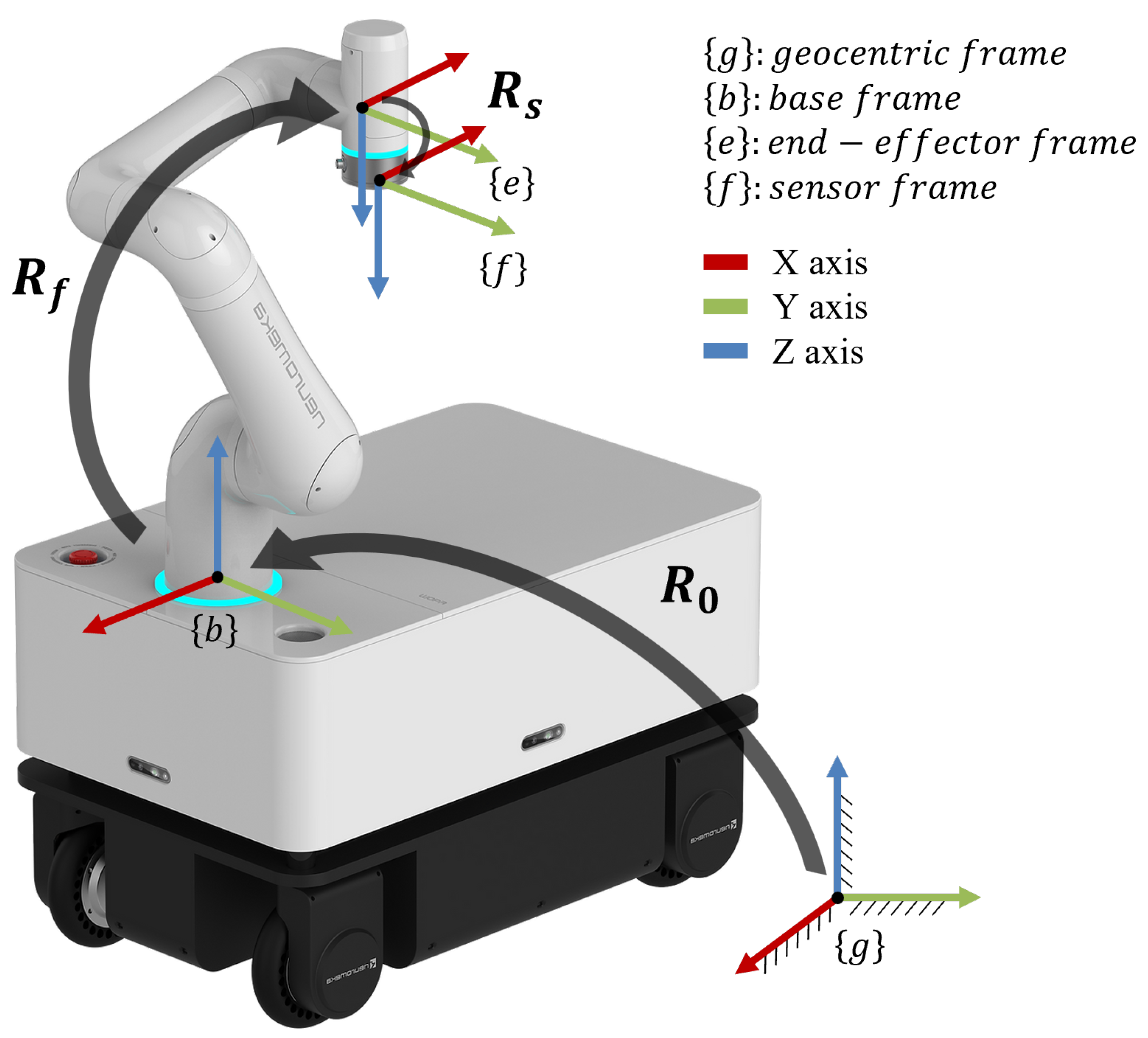
The coordinates described in fig:coordinate are used throughout this paper. Each rotation matrix between coordinates satisfies the following relationship:
Figure 1.
Coordinate definition on our mobile manipulator Moby from Neuromeka.
2.3. Calibration Model
The typical crosstalk value can be interpreted based on changes in the structure of the FT sensor due to deformation. These changes are estimated by analyzing the variation in strain gauges or capacitance and are then converted into force or torque. For strain gauges, the variation in the sensors installed on the structure is calculated through an internal matrix and converted into Force and Torque that the user can understand. On the other hand, in the case of capacitance-type sensors, raw data is generated by utilizing changes in the distance between electrodes on the installed substrate (parallel plates with normal displacement), the area changes due to shear force (parallel plates with shear displacement), and the angle and distance changes between electrodes orthogonal to the direction of the shear force (orthogonal plates with shear displacement). Similar to the strain gauge type, the data are processed through internal calculations to provide force and torque values to the user.
We model the wrench measured by the FT sensor as follows. Let the superscript denote the value measured by the FT sensor, the theoretical applied value, the bias present in the sensor, and our estimated value. Then, the wrench read by the sensor is defined as shown in Eq. (1).
represents the ideal force applied by the end-tool attached to the sensor, where force is expressed as and torque as . is the initial default value of each data point when the sensor is first activated, which varies with each boot. The C matrix is the crosstalk matrix, which maps the influence of torque on force. Our objective is to determine all terms on the right side of Eq. (1) to compensate for the wrench caused by the end tool attached to the sensor, thereby enabling the measurement of pure external force.
Since the caused by the end tool is due to gravity, it is necessary to calculate the body gravity in the coordinate. If the base frame coincides with the global coordinate system , this calculation can be simplified using the robot’s forward kinematics. However, if the base is inclined, it is essential to know the angle to accurately determine the direction of gravity which is described in frame .
Defining the orientation of the frame relative to the global frame by the roll, pitch, and yaw angles , and , respectively. The gravity acting in the frame can be formulated as in Eq. (2). It is important to note that since the normal vectors of the and frames can be aligned in opposite directions through two rotations, as in a pan-tilt configuration, it is sufficient to determine only and to obtain without fully calculating .
To estimate the force , physically exerted by the end tool on the sensor, is defined as shown in Eq. (3).
The body gravity of frame obtained from Eq. (2) is transformed to the sensor frame using forward kinematics, based on data received from the controller. The transformation matrix between the end-effector frame and the force sensor f frame represents any rotational misalignment due to sensor assembly error; however, this effect is minimal relative to other factors and can be reasonably approximated as an identity matrix.
Since the torque arises from the CoM displacement of the end tool and its weight in the frame, it can be expressed as shown in Eq. (4) using Eq. (2).
The vector represents the vector of CoM on the end tool in the coordinate system. Expanding the forward kinematics from the coordinate system to the coordinate system, if each element of is defined as , can be expressed in terms of the known variables through and the unknown variables , , , , and .
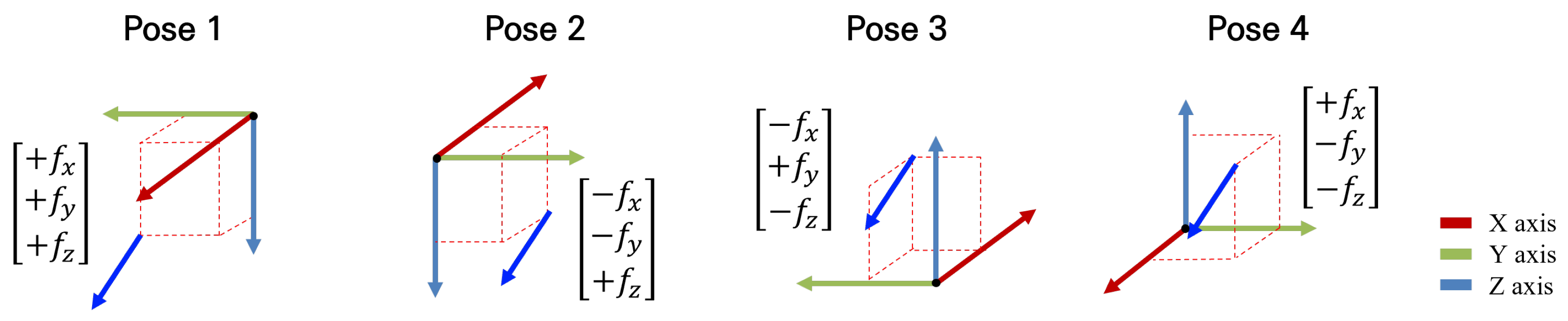
By using the sensor values obtained from the four postures shown in fig:bias, the bias values can be determined through Eq. (5).
When the same force is applied in the frame, the forces and torques from the four postures in fig:bias are composed of elements with identical magnitudes but opposite signs. Additionally, since the crosstalk effects we modeled is a linear combination of , it is dependent on the sign of . If two postures could be identified where each of the three axes has an opposite sign, it would be possible to cancel out all terms except using only those two postures. However, as such postures do not exist, we achieve the same effect through a combination of four postures. Consequently, by summing the sensor data from all four postures, we isolate the term composed solely of .
Figure 2.
The four initialization postures for bias estimation. When the same force is applied in the frame, the forces represented in the frame for each of the four postures are shown.
Figure 2.
The four initialization postures for bias estimation. When the same force is applied in the frame, the forces represented in the frame for each of the four postures are shown.
The crosstalk matrix is defined as shown in Eq. (6). This matrix represents the influence that a linear combination of torque values exerts on the force term. As mentioned above, forces and torques along the same axis do not affect each other in a capacitance-type FT sensor. Therefore, , representing the crosstalk from torque to force, is designed as a diagonal matrix with zeros to prevent mutual influence along corresponding axes. , representing the crosstalk from force to torque, is set to zero in our sensor configuration, as there is no observed impact of force on torque.
2.3.1. Linear Method
The CoM of the end tool can be obtained using Eq. (7). From the relation , we derive a linear equation in the form which can be solved by the least squares method. By constructing a matrix from the predicted values obtained across n postures, we can determine the CoM that minimizes the torque error in each posture through the pseudo-inverse.
The elements of the crosstalk matrix can be obtained using the linear Eq. (8). Since , we can vectorize and convert into matrix form by following the definition on Eq. (8) to achieve a least squares method structure, allowing the elements to be solved through the pseudo-inverse.
The tilt information of the base obtained from Eq. (2) is non-linear, making it impossible to determine parameters using a linear equation. Therefore, while compensation is possible with a linear equation on a flat surface, it is insufficient on an inclined surface. The case where CoM and crosstalk are calibrated using Eq. (7) and (8) with the LSM are labeled as LSM Calibration for the following experiments.
2.3.2. Non-Linear Method
The variables required to predict the sensor’s wrench include a total of 11 parameters: the CoM vector of the end tool, the inclined angle of the base, and the elements of the crosstalk matrix. To determine these variables, we design an objective function as shown in Eq. (10) and aim to minimize it using a nonlinear optimization technique.
By using the predicted values obtained through Eq. (3) and (4), along with the bias values from Eq. (5), we minimize the error with respect to the sensor data. Defining as Eq. (9), we set the objective function H as the summation of the values across n specified postures, allowing us to find the variables through gradient descent. The case where CoM, crosstalk, and inclination are calibrated using Eq. (10) are labeled as Full Calibration for the following experiments.
3. Experiments and Results
In this section, we apply our calibration method to a real robot and sensor, presenting the results. The mobile manipulator used is the Moby manufactured by Neuromeka shown in fig:coordinate, which consists of a 7-DOF manipulator and a mobile 4WIS-4WID platform. The FT sensor used is the AFT200 manufactured by AIDIN ROBOTICS, with detailed specifications provided in tab:ftsepc. The end tool used is the Robotiq’s 3-Finger Adaptive Gripper.

Table 1.
Specification of AFT200 FT sensor from ADIN ROBOTICS.
| Index | Value | Unit |
|---|---|---|
| Type | capacitance | - |
| Nominal force range | 200 | N |
| Nominal torque range | 15 | |
| Limit force () | 300 | N |
| Limit torque () | 25 | |
| Resolution () | 0.15 | N |
| Resolution () | 0.015 | |
| Maximum sample rate | 1,000 | Hz |
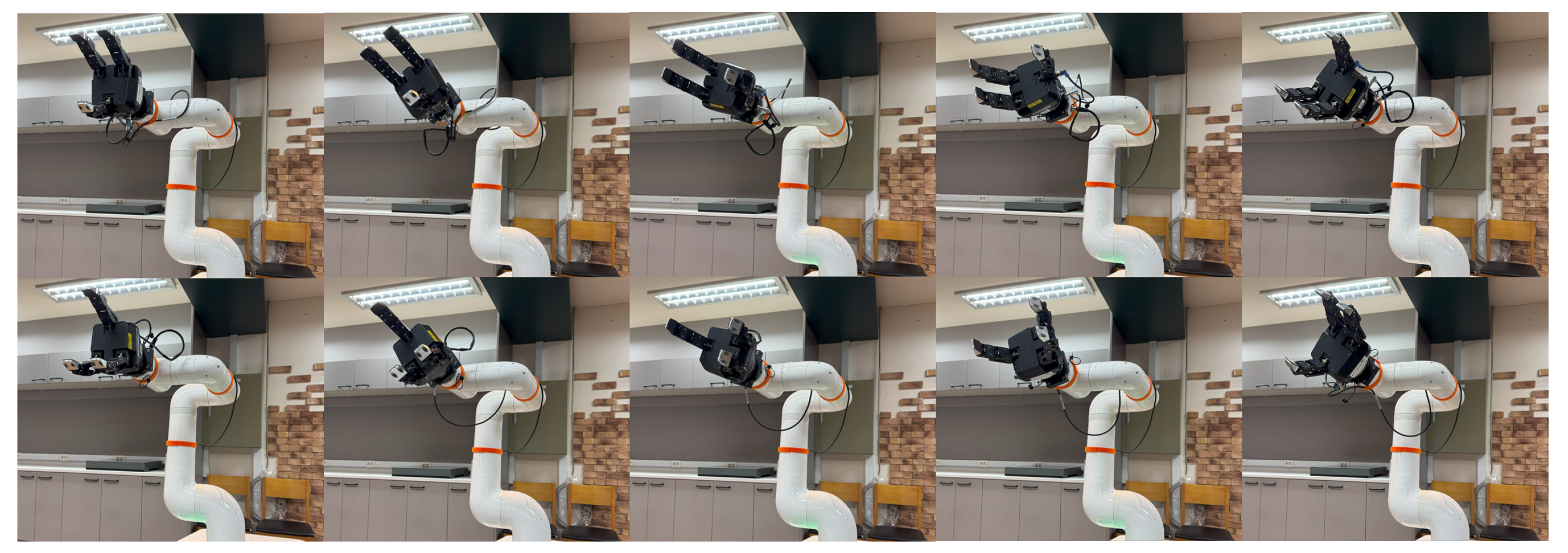
The data acquisition postures for calibration are shown in fig:samplingpose. In our case, the CoM of the end tool is the furthest along the z-axis in the coordinate system, resulting in the greatest torque generation. Therefore, data were collected from 10 postures that produce the highest torque. Depending on the shape of the end tool, users may choose different postures for calibration.
Figure 3.
10 sampling poses used for calibration throughout this paper. These postures are selected by rotating the wrist angle in the orientation that generates the highest torque, allowing for various orientations.
Figure 3.
10 sampling poses used for calibration throughout this paper. These postures are selected by rotating the wrist angle in the orientation that generates the highest torque, allowing for various orientations.
To assess the accuracy of the base inclined estimation, we first adjust the inclination of the mobile platform as shown in fig:tiltedbase and compare the results. The estimated base inclined angles are then compared with the geometric analysis, and the results are presented in tab:tiltestimationresult.
Figure 4.
The mobile base with an inclined. The inclined angle can be calculated geometrically using the wheelbase of the mobile robot and the height of the step.
Figure 4.
The mobile base with an inclined. The inclined angle can be calculated geometrically using the wheelbase of the mobile robot and the height of the step.
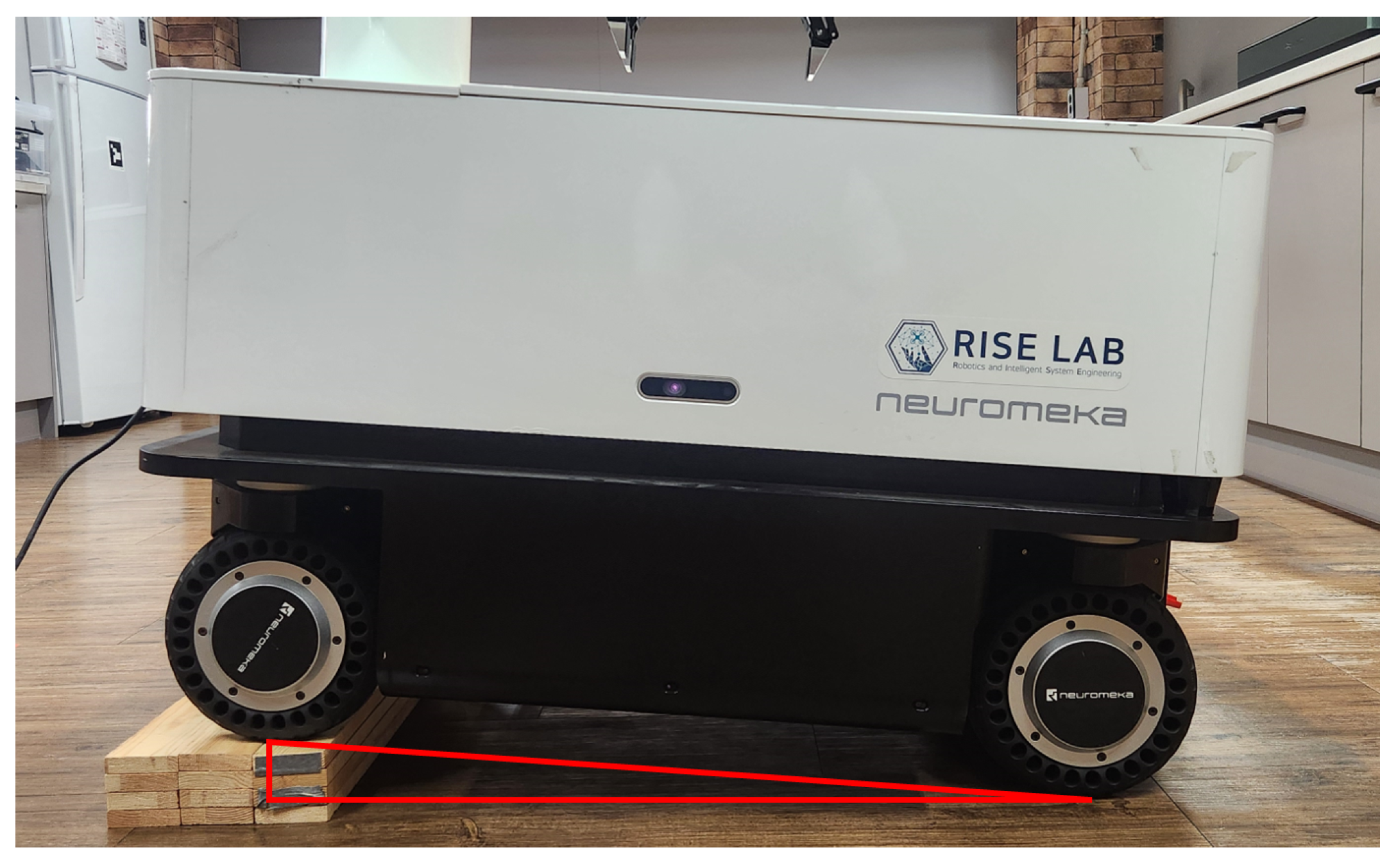
Table 2.
The result of inclined estimation. Since the geometrically calculated angle is not expressed as a rotation about our defined coordinate axes, we converted the results of our calibration into a screw angle to facilitate the comparison of magnitudes.
Table 2.
The result of inclined estimation. Since the geometrically calculated angle is not expressed as a rotation about our defined coordinate axes, we converted the results of our calibration into a screw angle to facilitate the comparison of magnitudes.
| Parameter | Kinematics [°] | Calibration Result [°] |
|---|---|---|
| - | 1.38 | |
| - | 4.88 | |
| screw angle | 4.8 | 5.07 |
To analyze the impact of each calibration parameter, we define the calibration levels for the following experiments as follows: cases where only bias calibration is performed are labeled as No Calibration; cases where CoM and crosstalk are calibrated using Eq. (7) and (8) with the LSM are labeled as LSM Calibration; and cases where floor inclined calibration using Eq. (10) is additionally performed using Eq. (3) are labeled as Full Calibration.
3.1. CoM Estimation
The CoM estimation based on the data obtained from fig:samplingpose yielded the results shown in tab:comestimationresult. Considering the data specified in the Robotiq 3-Finger Adaptive Gripper datasheet and the length of the mount we designed, the CoM along the z-axis is approximately 105 , while the estimated result is 104.4 . The difference in the CoM results for the x- and y-axes is due to the fact that our calibration aimed to estimate the wrench acting on the sensor. Therefore, the calibration was performed to predict the CoM in a way that minimizes the effect of the end tool on the sensor.
Table 3.
The result of CoM estimation.
| Parameter | Datasheet [] | Estimation [] |
|---|---|---|
| -8 | 4.7 | |
| 0.0 | -7.4 | |
| 1051 | 104.4 |
1 This data represents the values specified in the datasheet, with the addition of the height of the mount we designed.
3.2. Crosstalk Calibration
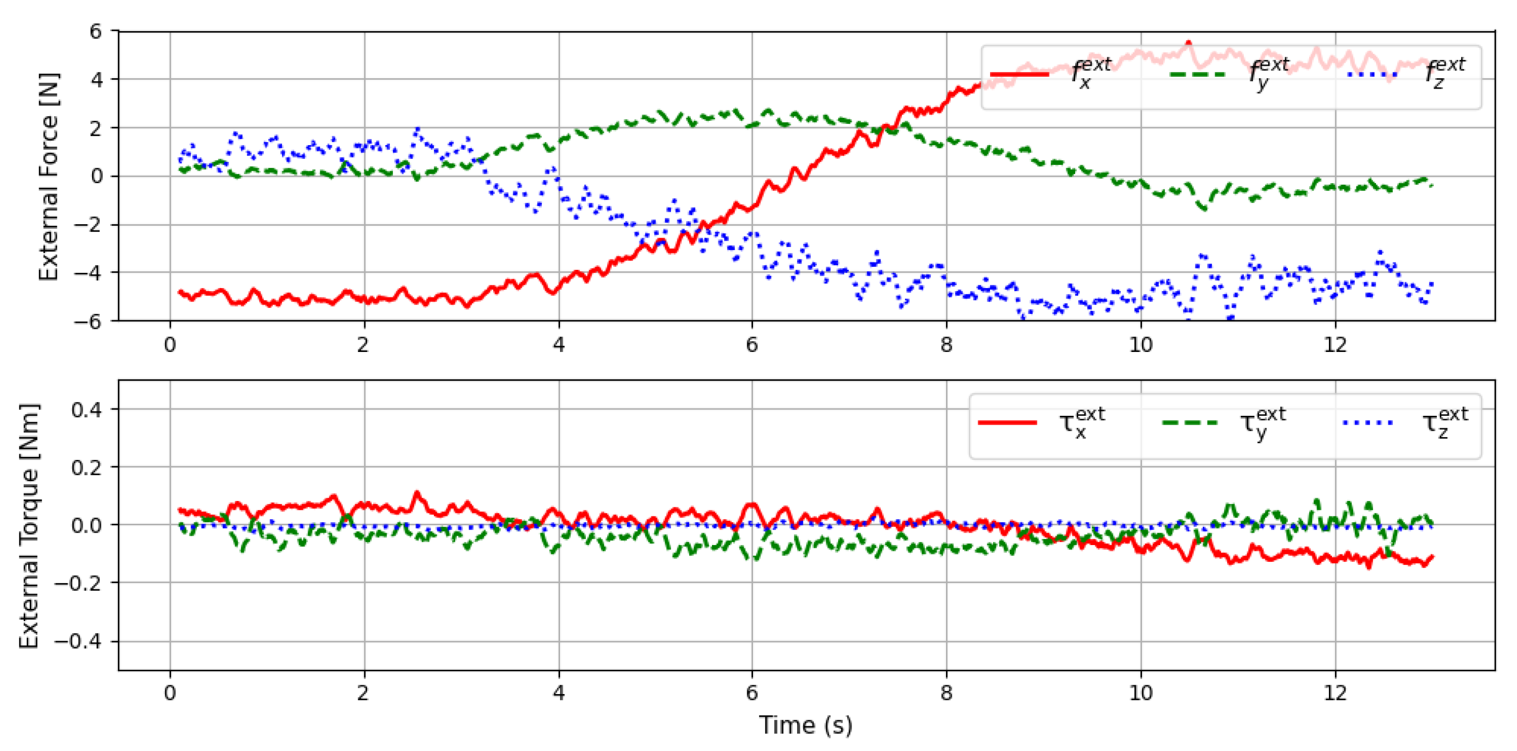
The reason for setting to zero when designing the crosstalk matrix is that torque is minimally affected by crosstalk. fig:ctvalid shows the results when the wrist angle of the end-effector is rotated 360 degrees, starting from a posture with the highest torque, as in the calibration data collection postures. In this case, the CoM estimated without any inclined was used, and no crosstalk calibration was performed. As a result, the exhibited significant errors due to the influence of crosstalk. In contrast, the showed a maximum error of 0.1 , indicating that the influence of crosstalk on torque is minimal. As shown in tab:crostalkvaliddata, the mean and variance of the external torque are very small. Therefore, our approach to modeling the crosstalk matrix is reasonable.
Table 4.
The table of the mean and variance of the external torque for each axis in data collected by rotating only the wrist in the sampling pose, without performing crosstalk calibration. To assess the relationship with the ideal value of zero, the mean and variance were calculated based on the absolute values of the data.
| Mean | Variance | Mean | Variance | Mean | Variance | |
| No Calib. | 0.059 | 0.002 | 0.062 | 0.002 | 0.015 | 0.0001 |
To evaluate whether the crosstalk calibration can compensate for the effects of the end tool’s own weight, we conducted an experiment using a Robotiq 3F gripper, trying a pick-and-place scenario on a non-inclined base. The path of the scenario is described in fig:pickandplacescenario. When the CoM is not estimated, the data from the gripper’s datasheet is used directly. During the experiment, the gripper does not grasp any object, and no external forces are applied. Ideally, the external wrench should be zero, where .
Figure 5.
The robot path in the pick-and-place scenario. The robot sequentially moves from posture 1 to posture 4, with posture 2 set at an angle of approximately 30 degrees to simulate a torque-generating situation.
Figure 5.
The robot path in the pick-and-place scenario. The robot sequentially moves from posture 1 to posture 4, with posture 2 set at an angle of approximately 30 degrees to simulate a torque-generating situation.
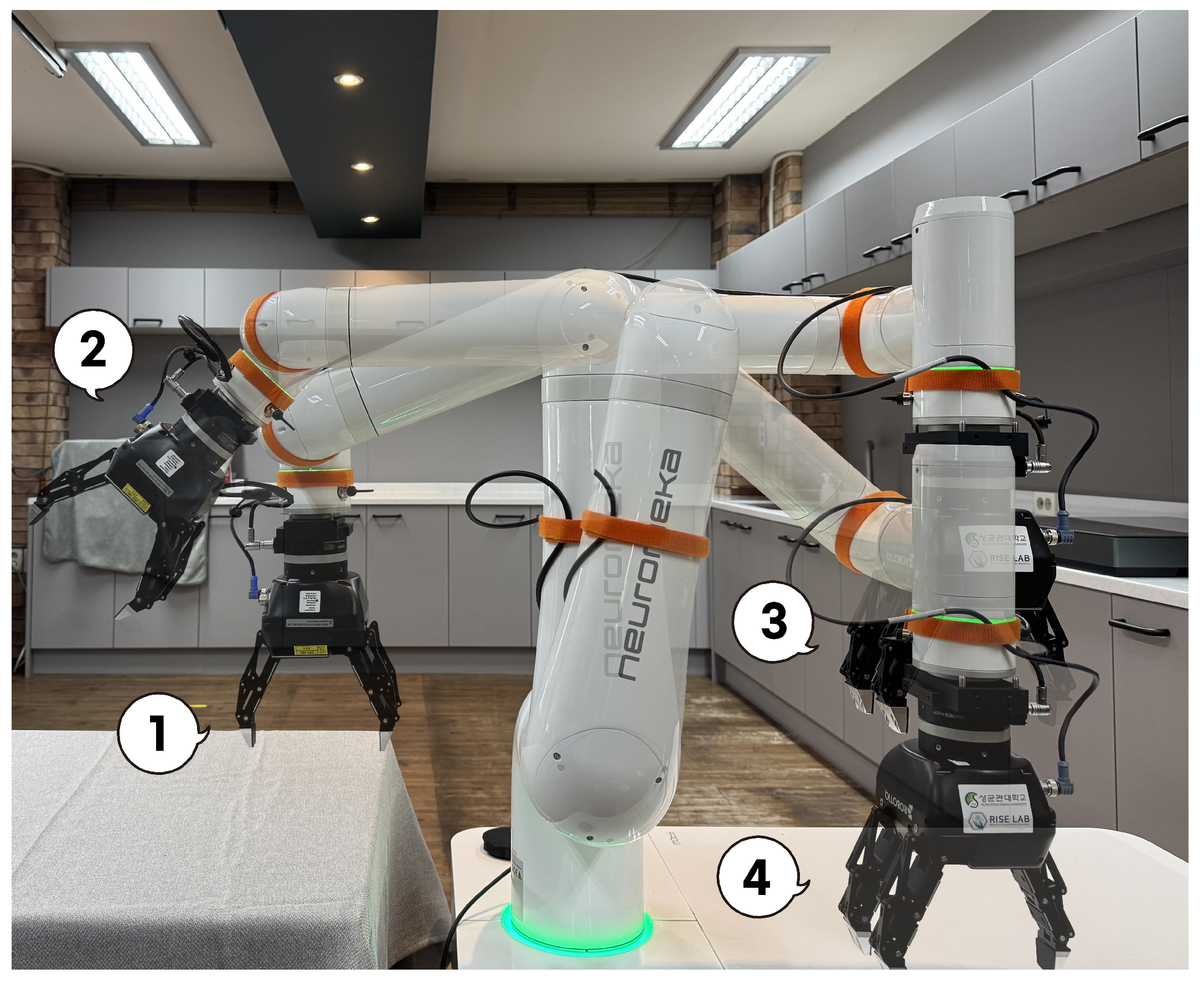
Figure 6.
The graph of external force and torque measured when the wrist is rotated in the sampling pose posture without crosstalk calibration. Since only the gripper is attached and no external forces are applied, the values should ideally converge to zero.
Figure 6.
The graph of external force and torque measured when the wrist is rotated in the sampling pose posture without crosstalk calibration. Since only the gripper is attached and no external forces are applied, the values should ideally converge to zero.
The first experiment is conducted on a non-inclined surface with an inclination of zero to investigate the impact of crosstalk. fig:flatnocalibhardshake shows the external force and torque graphs during the pick-and-place operation in the No Calibration, while fig:flatlsmcalibhardshake shows the same data for the LSM Calibration. As you can see in fig:flatresult, in postures where torque is generated due to the influence of the end tool, significant force errors are observed due to crosstalk. The analysis of the external force and torque data along each axis, as shown in fig:flatnocalibhardshake, is summarized in tab:flatcalibresultcompare. When crosstalk calibration was applied, the average external force decreased by approximately 33% along the x- and y-axes and by about 8% along the z-axis. The variance decreased by around 57% for the x-axes and y-axes and by about 15% for the z-axis. In contrast, the external torque showed almost identical results. This is because the estimated CoM closely matches the CoM specified in the datasheet, and no crosstalk compensation was applied for torque. Therefore, crosstalk compensation effectively reduces errors due to force.
Figure 7.
Two different data comparing the external force and torque when Figure 7 only No Calibration is applied and when Figure 7 LSM Calibration are applied on a non-inclined base. Since there is no inclined, Full Calibration does not affect the result.
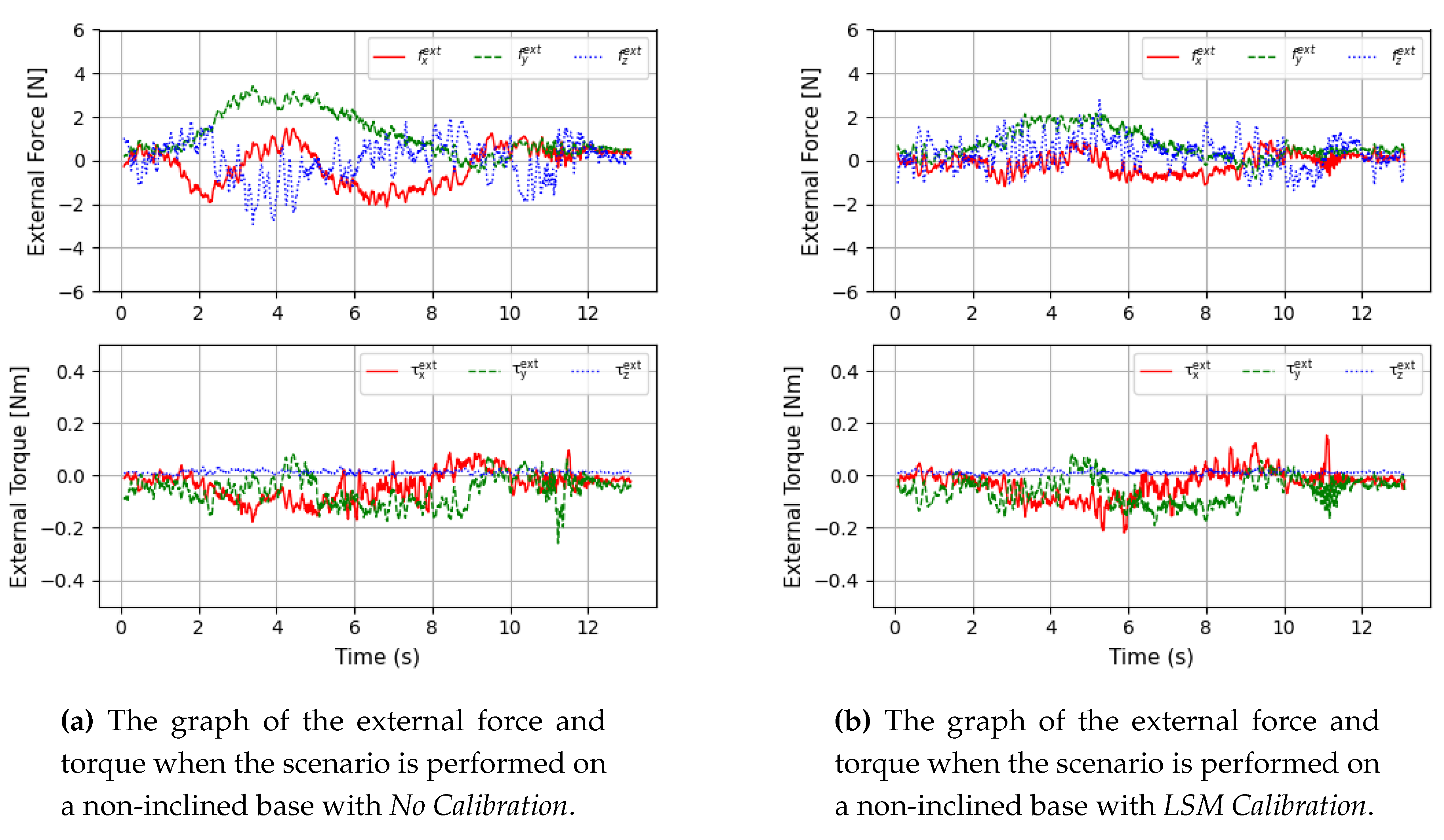
Table 5.
The table of the mean and variance of force and torque for each axis when calibration is performed using two methods on a non-inclined base.
Table 5.
The table of the mean and variance of force and torque for each axis when calibration is performed using two methods on a non-inclined base.
| Mean | Variance | Mean | Variance | Mean | Variance | Mean | Variance | Mean | Variance | Mean | Variance | |
| No Calib. | 0.858 | 0.349 | 1.262 | 1.014 | 1.185 | 0.530 | 0.075 | 0.004 | 0.085 | 0.005 | 0.019 | 0.0002 |
| LSM Calib. | 0.571 | 0.154 | 0.843 | 0.432 | 1.098 | 0.447 | 0.071 | 0.004 | 0.086 | 0.004 | 0.017 | 0.0001 |
3.3. Inclination Calibration
To investigate the impact of the inclined base, we conduct the second experiment in three calibration steps: No Calibration, LSM Calibration, and Full Calibration. The results of the experiment are shown in fig:tiltresult. The base is inclined by approximately 5 degrees as we set up in fig:tiltedbase. Comparing Figure 8 and Figure 8, we can see that while the external force error in fig:tiltlsmhardshake has decreased due to crosstalk compensation, the torque error remains due to the base’s inclined, indicating that the estimated CoM and crosstalk are insufficient to reduce the torque error. In fact, the torque error is the same as in fig:tiltnohardshake, where No Calibration is applied. Comparing Figure 8 and Figure 8, we observe that both force and torque have converged close to zero in fig:tiltfullhardshake. This result demonstrates effective compensation for the errors in force and torque caused by the base inclined, and compared to fig:tiltnohardshake, where No Calibration is applied, it shows that the influence of the end tool has been effectively compensated. Additionally, as mentioned in the CoM results, our calibration method compensates using the data provided by the sensor, enabling effective calibration from the sensor’s perspective even if there are discrepancies with the datasheet.
The analyzed experimental data is presented in the table. Figure 8 and Figure 8 showed a trend similar to that in fig:flatresult. Although crosstalk compensation reduced the force error, the presence of base inclined prevented convergence close to zero. Comparing the data in Figure 8 and Figure 8, we can see that estimating the inclined angle allowed the error to converge close to zero. For external torque, the mean values in the x, y, and z-axes decreased by 64%, 22%, and 32%, respectively, and the variance decreased by 82%, 17%, and 63%, respectively. Additionally, the final results in tab:flatcalibresultcompare, obtained from experiments on a non-inclined base, are nearly identical to the results obtained on an inclined base. Therefore, our calibration method achieves the same external force estimation accuracy on an inclined base as on an even floor.
We conduct the same pick-and-place motion with the gripper holding an object with 2 of mass. Since the gripper is grasping an object, the FT sensor measures the wrench resulting from both the gripper’s weight and the object’s weight. Given that the calibration was performed using the previously described method to compensate for the gripper’s weight, the external wrench should reflect only the effect of the object’s weight. The results of estimating the object’s mass under three conditions are shown in fig:massest. To estimate the mass of an object grasped by the gripper, we calculated the l2-norm of external force. However, the actual wrench applied is not ideally separated into force and torque components. In the No Calibration results, during the period between 2–8 seconds, where both force and torque are applied together, there is a significant fluctuation in the magnitude of the external force. This is due to the lack of ideal separation between force and torque, which requires the crosstalk calibration we propose. With LSM Calibration, force and torque separation is achieved, resulting in a more stable external force magnitude over the same period. However, due to the inclined base, there remains an offset from the true mass of 2 . Finally, in the Full Calibration results, where the base inclined is accounted for, the estimated mass converges closer to the actual 2 .
Figure 9.
The graph showing the mass estimation results for the three different calibration scenarios.
Figure 9.
The graph showing the mass estimation results for the three different calibration scenarios.
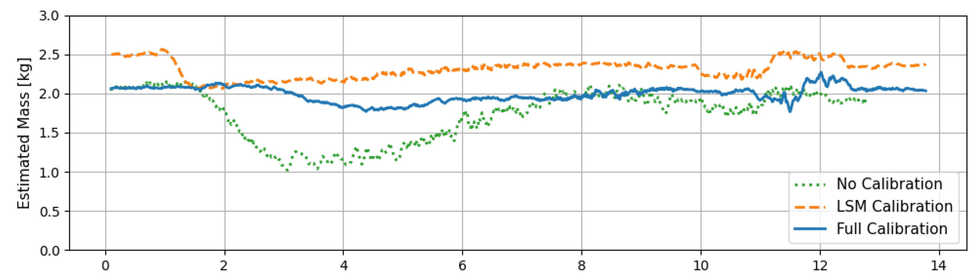
The analysis of mass estimation data from the three calibration stages in the pick-and-place scenario is shown in tab:massestimationresult. In the No Calibration results, the error is due to crosstalk from external torque, while in the LSM Calibration results, it is due to an offset from the inclined base. This is evident from the variance, which decreased by approximately 87%. The high variance in No Calibration reflects the failure to accurately separate force and torque, whereas in LSM Calibration the separation was successful, but an error remains due to the base inclined, affecting the gravity axis. With Full Calibration, compensating for the gravity axis error brought the estimated mass closer to 2 , and alignment of the gravity axis further reduced variance by an additional 36%.
Table 7.
The table of mass estimation results [] for the three different calibration scenarios.
| Mean | MAE | Variance | |
|---|---|---|---|
| No Calibration | 1.730 | 0.302 | 0.107 |
| LSM Calibration | 2.308 | 0.308 | 0.014 |
| Full Calibration | 1.993 | 0.081 | 0.009 |
The above results were obtained from dynamic data collected during the pick-and-place scenario. To ensure an accurate comparison, we also performed mass estimation under static conditions across various postures with different orientations, as shown in tab:massest5pose. The overall trends are consistent with the previous experiment: crosstalk compensation enabled force and torque separation, while inclined compensation allowed for more accurate estimations.
Table 8.
The table summarizes the mass estimation results [] across five different orientations for each of the three calibration scenarios.
Table 8.
The table summarizes the mass estimation results [] across five different orientations for each of the three calibration scenarios.
| Pose 1 roll: 28.8° pitch: 165.7° yaw: 27.7° |
Pose 2 roll: 53.5° pitch: -171.4° yaw: 99.7° |
Pose 3 roll: 140.6° pitch: 24.2° yaw: 109.2° |
Pose 4 roll: -43.9° pitch: -154.2° yaw: 46.1° |
Pose 5 roll: -66.1° pitch: -170.7° yaw: 179.74° |
Mean | MAE | Variance | |
|---|---|---|---|---|---|---|---|---|
| No Calib. | 2.58 | 2.26 | 1.14 | 1.08 | 1.25 | 1.66 | 0.674 | 0.496 |
| LSM Calib. | 2.26 | 2.28 | 1.64 | 2.10 | 2.07 | 2.07 | 0.214 | 0.067 |
| Full Calib. | 2.22 | 2.28 | 1.70 | 1.97 | 2.08 | 2.05 | 0.182 | 0.053 |
4. Conclusion
In this paper, we introduce a calibration method for accurately obtaining external forces by modeling an FT sensor to determine essential parameters, including bias, crosstalk, CoM, and inclination. Although discrepancies can exist between the FT sensor’s measured data and actual physical quantities, our goal is to model the sensor to minimize the error between the FT sensor data and the predicted values to obtain accurate external forces. Tasks requiring interaction with the environment through a robot necessitate the attachment of an end tool. To isolate contact forces with the external environment, it is essential to compensate for the wrench due to the end tool’s weight, which we achieve through calibration. Notably, adding inclined angle calibration, found to be the most critical factor, improves compensation performance. In Result, we evaluated whether calibration was appropriately applied in response to changes in the environment. Our calibration results showed that on a non-inclined base, crosstalk and CoM adjustments reduced the overall mean error by approximately 14% and variance error by 38%. On an inclined base, the overall mean error decreased by about 42%, and the variance error was reduced by around 65%. These results indicate that working on an inclined base can significantly impair accurate external force estimation using FT sensors, underscoring the necessity of our calibration method, including inclined compensation, to ensure consistent FT sensor performance. We expect that the proposed calibration method will be valuable in applications like mobile manipulators, where environments change frequently and interaction with the environment is essential.
Author Contributions
Conceptualization, J.-y.S. and J.-j.S.; methodology, J.-y.S. and J.-j.S.; software, J.-y.S. and J.-j.S.; validation, J.W.; formal analysis, J.-y.S., J.-j.S., J.W., and E.A.; investigation, J.-y.S., J.-j.S., and J.W.; data curation, J.-y.S., J.-j.S., and E.A.; writing—original draft preparation, J.-y.S., and J.-j.S.; writing—review and editing, E.A. and H.-r.J.; visualization, J.-y.S. and J.-j.S.; supervision, H.M.; project administration, H.-r.J. and H.M.; funding acquisition, H.M.; All authors have read and agreed to the published version of the manuscript.
Funding
This research was supported in part by the MSIT(Ministry of Science and ICT), Korea, under the ITRC(Information Technology Research Center) support program(IITP-2024-2020-0-01460) supervised by the IITP(Institute for Information & Communications Technology Planning & Evaluation); and in part by Institute of Information & communications Technology Planning & Evaluation (IITP) grant funded by the Korea government(MSIT) (No.2022-0-01025, Development of core technology for mobile manipulator for 5G edge-based transportation and manipulation).
Abbreviations
The following abbreviations are used in this manuscript:
| CoM | Center of Mass |
| DOF | Degrees of Freedom |
| FT Sensor | Force-Torque Sensor |
| LSM | Least Squares Method |
| 4WIS-4WID | Four-Wheel Independent Steering and Driving |
References
- Ott, C.; Mukherjee, R.; Nakamura, Y. Unified impedance and admittance control. In Proceedings of the 2010 IEEE international conference on robotics and automation. IEEE; 2010; pp. 554–561. [Google Scholar]
- Tadese, M.A.; Yumbla, F.; Pico, N.; Moon, H. Application of A Reliable Dynamic Friction Model for Accurate Dynamic Model Parameters Estimation of Robot Manipulators. In Proceedings of the 2022 22nd International Conference on Control, Automation and Systems (ICCAS); 2022; pp. 1916–1923. [Google Scholar] [CrossRef]
- Swevers, J.; Verdonck, W.; De Schutter, J. Dynamic model identification for industrial robots. IEEE control systems magazine 2007, 27, 58–71. [Google Scholar]
- Wu, J.; Wang, J.; You, Z. An overview of dynamic parameter identification of robots. Robotics and computer-integrated manufacturing 2010, 26, 414–419. [Google Scholar] [CrossRef]
- Kermani, M.R.; Patel, R.V.; Moallem, M. Friction identification and compensation in robotic manipulators. IEEE Transactions on Instrumentation and Measurement 2007, 56, 2346–2353. [Google Scholar] [CrossRef]
- Kim, Y.B.; Seok, D.Y.; Lee, S.Y.; Kim, J.; Kang, G.; Kim, U.; Choi, H.R. 6-Axis Force/Torque Sensor With a Novel Autonomous Weight Compensating Capability for Robotic Applications. IEEE Robotics and Automation Letters 2020, 5, 6686–6693. [Google Scholar] [CrossRef]
- Oh, H.S.; Kim, U.; Kang, G.; Seo, J.K.; Choi, H.R. Multi-Axial Force/Torque Sensor Calibration Method Based on Deep-Learning. IEEE Sensors Journal 2018, 18, 5485–5496. [Google Scholar] [CrossRef]
- Su, H.; Qi, W.; Hu, Y.; Sandoval, J.; Zhang, L.; Schmirander, Y.; Chen, G.; Aliverti, A.; Knoll, A.; Ferrigno, G.; et al. Towards model-free tool dynamic identification and calibration using multi-layer neural network. Sensors 2019, 19, 3636. [Google Scholar] [CrossRef] [PubMed]
- Wang, Y.J.; Hsu, C.W.; Sue, C.Y. Design and calibration of a dual-frame force and torque sensor. IEEE Sensors Journal 2020, 20, 12134–12145. [Google Scholar] [CrossRef]
- Wang, N.; Zhou, J.; Zhang, X. Research on the estimation of sensor bias and parameters of load based on force-feedback. In Proceedings of the Intelligent Robotics and Applications: 11th International Conference, ICIRA 2018, Proceedings, Part I 11. Springer, 2018. Newcastle, NSW, Australia, August 9–11 2018; pp. 404–413. [Google Scholar]
- Yang, X.; Li, F.; Gao, R.; Song, R.; Li, Y. Force perception of industrial robot based on multi-parameter coupled model. In Proceedings of the 2019 IEEE International Conference on Robotics and Biomimetics (ROBIO). IEEE; 2019; pp. 1676–1681. [Google Scholar]
- Yu, Y.; Shi, R.; Lou, Y. Bias estimation and gravity compensation for wrist-mounted force/torque sensor. IEEE Sensors Journal 2021, 22, 17625–17634. [Google Scholar] [CrossRef]
- Kim, Y.L.; Park, J.J.; Song, J.B. Crosstalk calibration for torque sensor using actual sensing frame. Journal of mechanical science and technology 2010, 24, 1729–1735. [Google Scholar] [CrossRef]
- Ding, C.; Han, Y.; Du, W.; Wu, J.; Xiong, Z. In situ calibration of six-axis force–torque sensors for industrial robots with tilting base. IEEE Transactions on Robotics 2021, 38, 2308–2321. [Google Scholar] [CrossRef]
Figure 8.
The Graph comparing the external force and torque when calibration is performed using three methods on an inclined base.
Figure 8.
The Graph comparing the external force and torque when calibration is performed using three methods on an inclined base.
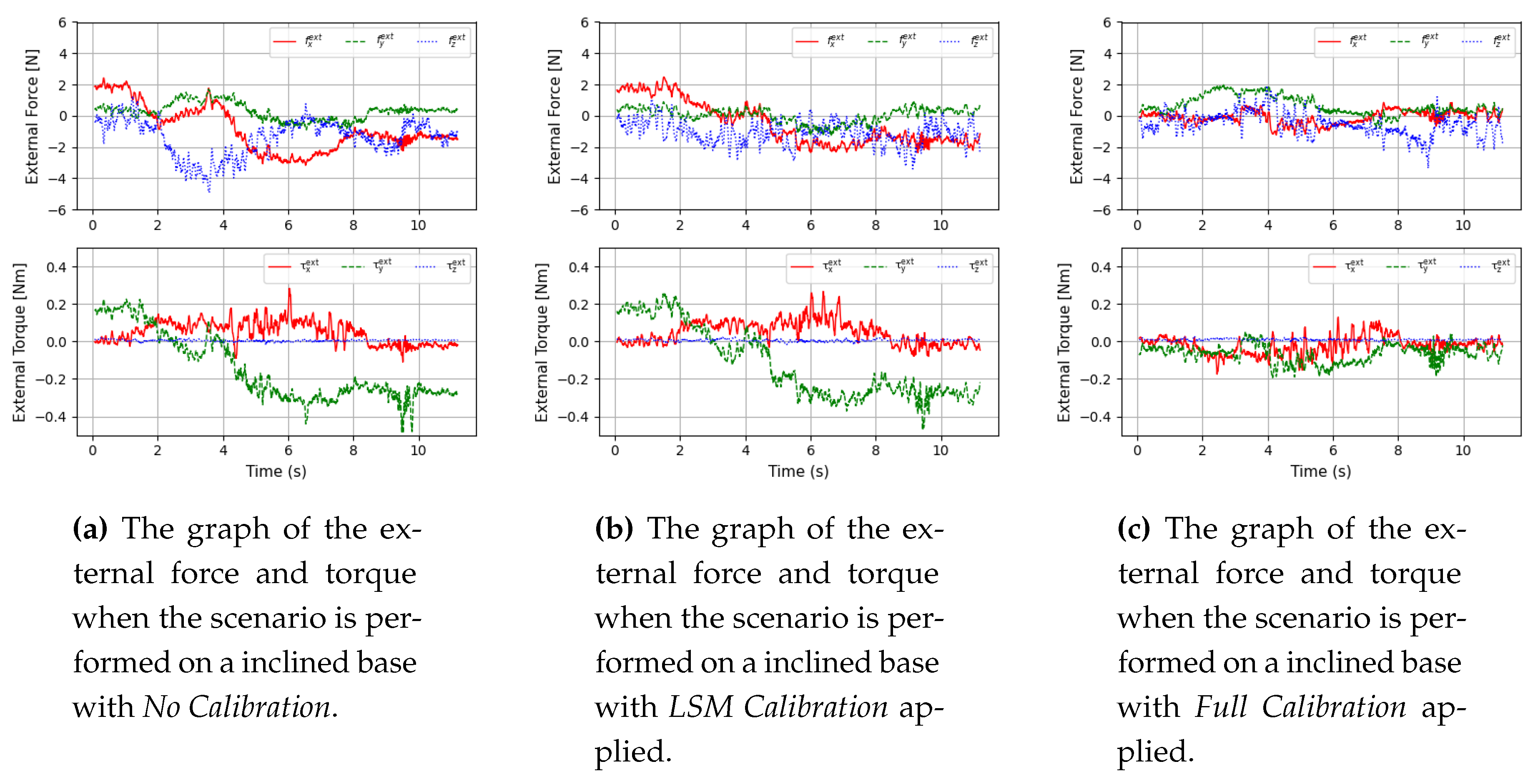
Table 6.
The table of the mean and variance of force and torque for each axis when calibration is performed using three methods on an inclined base.
Table 6.
The table of the mean and variance of force and torque for each axis when calibration is performed using three methods on an inclined base.
| Mean | Variance | Mean | Variance | Mean | Variance | Mean | Variance | Mean | Variance | Mean | Variance | |
| No Calib. | 1.509 | 0.835 | 0.648 | 0.230 | 1.679 | 1.594 | 0.088 | 0.005 | 0.211 | 0.015 | 0.014 | 0.0001 |
| LSM Calib. | 1.384 | 0.539 | 0.526 | 0.191 | 1.366 | 0.960 | 0.081 | 0.005 | 0.206 | 0.014 | 0.015 | 0.0001 |
| Full Calib. | 0.537 | 0.153 | 0.506 | 0.190 | 1.148 | 0.586 | 0.068 | 0.003 | 0.088 | 0.005 | 0.015 | 0.0001 |
Disclaimer/Publisher’s Note: The statements, opinions and data contained in all publications are solely those of the individual author(s) and contributor(s) and not of MDPI and/or the editor(s). MDPI and/or the editor(s) disclaim responsibility for any injury to people or property resulting from any ideas, methods, instructions or products referred to in the content. |
© 2024 by the authors. Licensee MDPI, Basel, Switzerland. This article is an open access article distributed under the terms and conditions of the Creative Commons Attribution (CC BY) license (http://creativecommons.org/licenses/by/4.0/).
Copyright: This open access article is published under a Creative Commons CC BY 4.0 license, which permit the free download, distribution, and reuse, provided that the author and preprint are cited in any reuse.


