
Submitted:
29 October 2024
Posted:
30 October 2024
You are already at the latest version
Abstract
Designing a ship hull is a complex procedure that involves constructing the basic hull using predetermined criteria or specified lines. Grasshopper, a visual programming environment for Rhinoceros 3D (CAD software), has a parametric modeling and analysis tool that automates the generation of ship hull and line plans using offset tables. This strategy reduces the necessity of manual design while enhancing efficiency and precision. Grasshopper is widely used for generating designs, enabling designers to visually create intricate algorithms by connecting components instead of writing code. This paper proposes a novel technique to automate the construction of ship hull and line plans with Grasshopper, leveraging its parametric capabilities to produce hull shapes and plan lines readily from offset table data. Future advancements may involve combining hydrostatic and hydrodynamic evaluations, improving hull performance, and automating the fairing process. A user-friendly interface and real-time collaboration tools can boost accessibility and design flexibility.
Keywords:
Automation
; Offset Table
; Parametric
; Grasshopper
; Lines plan
1. Introduction
Designing a ship hull is culturally understood as a design art where the primary hull is first formed either from preset parameters or from the designed lines of additional conceived by the work designer which details coordinated for drift correction and post drafting. Further along, an offset table would be presented which showed the coordinates of the structural parts of the vessel. Such coordinates depict a particular ‘arc’ depicting the hull configuration of the vessel at a sectioned length along the vessel's cross frame. Depending on the position of the cut, the coordinates assigned to whine shaped lines which composed the curved frame structure depict the shape of the framing, and the position on the surface of the vessels submerged hull shows. Offsetting the shape of a spline radial makes it possible to obtain a model of the hull which aspires to have the most optimal design, through thrust optimization. There exists a method where designers, rather than determining superelevation lines or specific data of the hull, have moved to the construction of lines where a very vexing shape results in more trouble than what it is worth to resolve.
To undertake these obstacles, researchers have delved into the usage of computer-aided design and automation technologies. Grasshopper is a visual programming environment for Rhinoceros 3D (CAD Software). It has a huge library of blocks written in GhPython language which can be used for parametric modeling and analysis. It enables the automation of forming ship hull and line plans from offset tables. This decreases the need for manual drawing, ultimately improving the efficiency and accuracy of the design process. This enables designers to create complex algorithms visually by dragging and connecting components rather than writing codes. Grasshoppers are frequently used for producing generative designs, in which the shape of an object is formed using parameters (inputs), providing designers with greater control over geometry and the ability to iterate quickly.
This paper presents a unique approach for automating the creation of ship hull and line plans using Grasshopper. The method makes the most of the parametric capabilities of Grasshopper to generate hull forms, and the corresponding lines are effortlessly planned from offset table data, reducing the time and effort required for manual design repetitions. Nonetheless, the study decided to leave out hydrostatic and hydrodynamic analyses, choosing to only examine the geometric portrayal of the hull form. Future developments could include integrating hydrostatic and hydrodynamic analyses, optimizing hull performance, and automating the fairing process. Enlarging to different hull types, integrating specialized ship design software (Ship Constructor, NAPA, Maxsurf), and automating creation of drawings would enhance serviceability. A user-friendly interface and real-time cooperation tools can improve attainability and design flexibility.
2. Literature Review
The use of parametric modeling tools has resulted in considerable breakthroughs in ship hull design, simplifying the complicated geometry involved. Bole and Forrest [1] were pioneers in incorporating integrated parametric design into the early stages of ship development, emphasizing the necessity for automation to reduce the manual work necessary to shape the hull shapes. In a similar spirit, Pavel's tutorial on using Grasshopper as a visual programming environment in Rhinoceros 3D to apply parametric design concepts proved quite effective in automating hull form synthesis. Artificial intelligence approaches were also used in the design of hull shapes. Islam et al. [3] discussed the use of artificial intelligence approaches to automatically build hull forms. Their work focused on the benefits of AI design in terms of efficiency and accuracy, as well as how AI reduces the number of man-hours required to do repetitive tasks. Pirker [4] expanded on this by focusing on the automated variation and optimization of grid structures--an idea that might be used to the construction of ship hulls to achieve maximum structural efficiency. Another significant addition has been the creation of customized Rhino/Grasshopper tools, such as those proposed by Guilcher and Laurens [5], who in their paper proposed a set of tools for ship design automation. The adaptability of Grasshopper, which was built for many maritime design contexts, was highlighted. Katsoulis et al. [7] suggests a T-splines-based parametric modeler applied to computer-aided ship design within the larger framework of implementing the idea of parametric ship design. Their work concentrated on demonstrating the viability of using parametric models to include hydrodynamic studies about hull performance in addition to complex geometries construction. Previous research emphasizing the value of incorporating these studies can be found in Lewis's [8] exposition of the fundamental ideas of naval architecture, which focused on the performance-based design of the hull. Grigoropoulos talked on optimizing hull form based on hydrodynamic performance and provided some techniques for designing hull shapes that maximize stability and fuel efficiency. The study falls under Panikolaou's holistic approach to ship design, which combined many aspects of ship performance into a single, integrated design optimization process. The parametric method has also been investigated in the field of architecture design for the purpose of creating free-form structures. Grasshopper was utilized in the work by Glymph et al. [11] to produce intricate glass structures, demonstrating its potential for ship hull design through the automation of challenging geometric tasks. Additionally, McNeel's work [12] has shed light on the construction of ship hulls using offset tables, a concept that combines Grasshopper's parametric features to generate hulls in an automated manner. The approach of automatic analysis, which includes digital hull design, model processing, and evaluation, was also highlighted by Xing et al. [13], advancing the field's objective of fully automated ship design workflows.
3. Methodology
The workflow begins by reading the offset table, generating smooth curves through parametric interpolation, and lofting these curves to create a hull surface. The entire process is automated, allowing real-time adjustments and optimization
- A.
- Assumptions:
Nonetheless, the offset table format must be transposed for this grasshopper application. As illustrated in Figure 1 , the stations represent the columns of the table, and the waterlines represent their rows. Furthermore, the table must begin with Excel Sheet's A1 cell and cannot contain any letters.
To read the Excel table Grasshopper needs an additional plugin named TT toolbox by food4rhino [6] which must be preinstalled before using this script.
- B.
- Data Input:
The input section contained four elements presented in Figure 2. The Excel file of our Offset Table should be imported in the ‘Offset Table’ block. The yellow ‘Table block’ takes the entity of the specific sheet name (OT) in the Excel file in which the offset table is saved. ON/OFF (True) indicates that the system is active and the read? The (True) block confirms that data reading is enabled, allowing interaction with the OT table.
- C.
- Generate Points:
In Figure 3 this part is designed to extract and organize a cloud of points and dimensions from an offset table. It begins by reading the Excel sheet through a ‘Read Excel Sheet’ block (tt toolbox), which takes inputs from the input section and reads the Excel sheet as a tree of lists. Next, the columns are divided into two lists so that the Z-coordinates of the points in the waterline height column can be separated. The station’s longitudinal position row, which contains the X coordinates of the points, is then separated using further split operations inside the list of other columns. These data were separated into positive and negative values by a split tree function using applied masks to organize the point Y coordinates. The ‘Concatenate’ function assembles these values into 3D coordinates (X, Y, Z) visualized in Figure 4. Finally, item blocks were used to retrieve and output specific dimensional values, such as length, height, and breadth, effectively automating the process of converting tabular data into points.
- D.
- Generation of Sections:
In this stage (shown in Figure 5), the points generated are interpolated using the ‘Interpolate’ block to generate curves through points, and section curves shown in Figure 6 are obtained according to the stations of the offset table.
- E.
- Generation of the Hull Surface
Figure 7 shows the next step, where the 3D hull surface is formed by lofting the section curves. A bottom surface was also generated using the ‘RuleSrf’ block and joined with the lofted surface to fully create the port side of the vessel hull. Mirroring forms on the opposite side of the hull.
- F.
- Body Plan:
In Figure 8, after creating the hull surface, Section curves are divided into two parts (aft & fwd. amidship) from the middle using ‘Subset,’ and the aft part is mirrored using ‘Mirror.’ The curves were then moved to the YZ-plane to create a single-plane drawing. The ‘Body Plan Grid’ block creates the grid of the body plan using the water line spacing and height from the offset table.
- G.
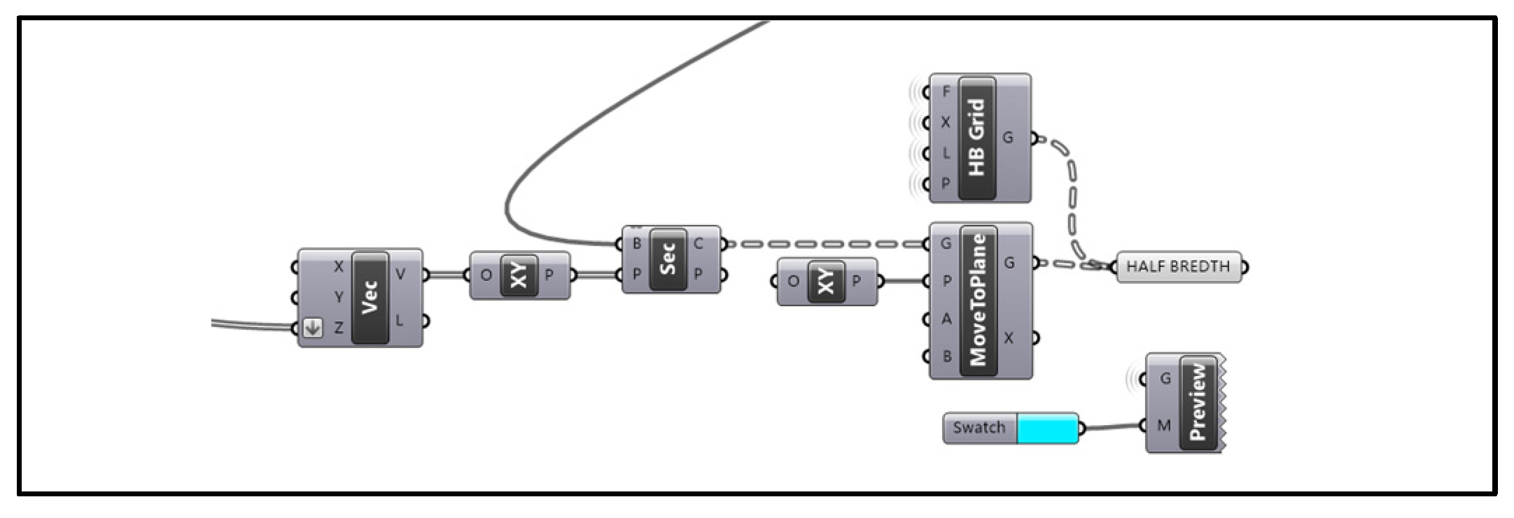
- Half Breadth Plan:
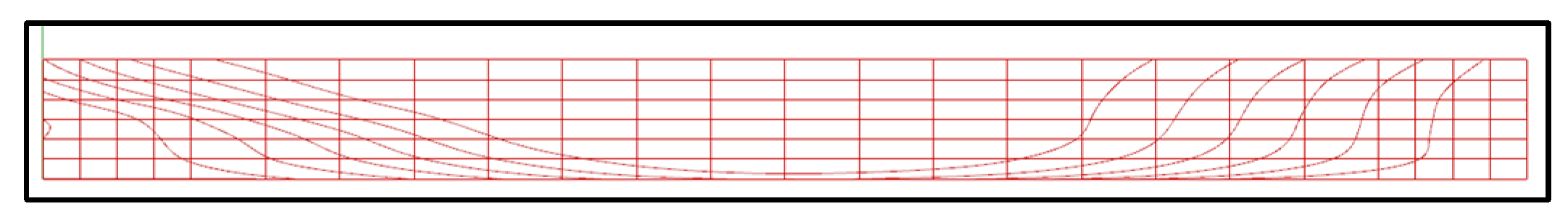
The value of the waterline height is passed to the Z input ‘Vec’ block to create coordinates (for example, (0, 0, Z)). XY section planes are created at those vector points (water planes), which form the cross-sectional curves of the hull surface at the waterline heights. Subsequently, all the curves were moved to plane XY to form a single plane drawing. The ‘HB Grid’ block creates the grid of the Half Breadth Plan using the station spacing and breadth from the offset table.
Figure 9.
Half Breadth Generation Section.
- H.
- Profile Plan:
This part, shown in Figure 10, begins by creating a boundary box around the half hull. The number of buttock lines can be changed by using a slider. ‘Perpendicular Frame’ block creates equally spaced breadth wise planes (buttock planes). Again, using the ‘Section’ block, the cross-sectional curves of the hull at those planes are generated. These curves were then moved to the X–Z plane. ‘Profile Grid’ creates a grid of profile view which contains stations and water lines.
- I.
- Arrangement:
This is the last section in Figure 12, where all outputs (Hull, Body plan, half-breadth plan, and profile) are arranged. This section rotates and moves the three plans at the XY plane and aligns with each other to create a full-line plan drawing. provides the final output for the entire program.
4. Results And Discussion
The results of this study demonstrate the effectiveness of automating ship hull and line plan generation using the Grasshopper. By inputting an offset table, the Grasshopper script successfully produced smooth Hull Surface (Figure 13), Body Plan (Figure 14), Half Breadth Plan (Figure 15), Profile Plan (Figure 16) from the given Offset table.
The parametric method of Grasshopper allowed for immediate changes of the hull shape. Any modifications in the offset table, like distance between stations or size of the hull, could be smoothly integrated into the model without re-running the whole process. The hull from the offset table was also much more accurate than the one manually created. Automation of hull and line plan generation offers major benefits in time efficiency and flexibility, at least during the initial design stage. More powerful parametric capabilities in Grasshoppers now allow designers to quickly create and refine designs, with only minor manual work needed to test different variants of a hull. This process is also still largely unusable during the final stages of design due to the lack of hydrodynamic analysis. Even more valuable information could be obtained by incorporating some performance calculations into Grasshopper. While the parametric approach saves a great deal of time and offers much more freedom, there are also some disadvantages in using this approach-for example, how interpolation error relates to the design at hand, especially in complex hull shapes. Another challenge is that such incorporation of Grasshopper with other software-that indeed will perform hydrodynamic analysis-must be made in a manner to ensure seamless data exchange. Notwithstanding such challenges, automation in ship hull design is too good an offer to let pass by modern naval architecture.
5. Conclusion
The research showed that Grasshopper works effectively in the automation of ship hull and line plan generations. In essence, the parametric approach facilitates the direct translation of offset table data into an accurate three-dimensional model complete with a line plan, where changes are made in real time. While the present methodology involves only the basic geometry of the hull, without complex features and hydrodynamic analysis, the methodology saves considerable time and offers flexibility in the early design stages of ships. Further development could give the approach a valid tool for the improvement of ship hull design in naval architecture.
6. Disclosure
The author was only responsible for the conceptualization, methodology, data collection, analysis, and writing of this research paper.
There is no conflict of interest. No external funding was received for this research. The data supporting the findings of this study are available from the author upon reasonable request. This study does not involve human participants, animal subjects or any data that require ethical approval.
All procedures performed followed relevant institutional and legal requirements.
Appendix
A sample offset table.
| Position | WL 1 | WL 2 | WL 3 | WL 4 | WL 5 | WL 6 | WL 7 | |
| 0 | 1.3 | 2.6 | 3.9 | 5.2 | 6.5 | 7.8 | ||
| St 0 | 0.00 | 0.00 | 0.00 | 0.00 | 0.00 | 0.63 | 2.20 | 3.44 |
| St .5 | 2.43 | 0.02 | 0.23 | 0.24 | 0.31 | 1.48 | 3.27 | 4.67 |
| St 1 | 4.87 | 0.08 | 0.52 | 0.61 | 0.83 | 2.36 | 4.19 | 5.58 |
| St 1.5 | 7.30 | 0.18 | 0.86 | 1.08 | 1.49 | 3.24 | 4.98 | 6.26 |
| St 2 | 9.73 | 0.36 | 1.27 | 1.61 | 2.27 | 4.09 | 5.66 | 6.77 |
| St 3 | 14.60 | 0.90 | 2.25 | 2.80 | 3.95 | 5.63 | 6.76 | 7.48 |
| St 4 | 19.46 | 1.58 | 3.31 | 4.18 | 5.49 | 6.81 | 7.54 | 7.91 |
| St 5 | 24.33 | 2.41 | 4.52 | 5.62 | 6.68 | 7.52 | 7.94 | 8.11 |
| St 6 | 29.19 | 3.34 | 5.74 | 6.87 | 7.55 | 7.92 | 8.10 | 8.20 |
| St 7 | 34.06 | 4.24 | 6.77 | 7.71 | 8.02 | 8.12 | 8.17 | 8.20 |
| St 8 | 38.92 | 5.07 | 7.49 | 8.10 | 8.20 | 8.20 | 8.20 | 8.20 |
| St 9 | 43.79 | 5.74 | 7.88 | 8.20 | 8.20 | 8.20 | 8.20 | 8.20 |
| St 10 | 48.65 | 6.09 | 8.04 | 8.20 | 8.20 | 8.20 | 8.20 | 8.20 |
| St 11 | 53.52 | 5.83 | 7.94 | 8.17 | 8.20 | 8.20 | 8.20 | 8.20 |
| St 12 | 58.38 | 5.20 | 7.69 | 8.06 | 8.10 | 8.13 | 8.12 | 8.15 |
| St 13 | 63.25 | 4.22 | 7.15 | 7.65 | 7.74 | 7.81 | 7.89 | 7.98 |
| St 14 | 68.11 | 3.08 | 6.32 | 6.98 | 7.14 | 7.25 | 7.43 | 7.64 |
| St 15 | 72.98 | 1.96 | 5.24 | 5.91 | 6.16 | 6.38 | 6.63 | 7.00 |
| St 16 | 77.84 | 1.06 | 4.00 | 4.62 | 4.88 | 5.11 | 5.46 | 6.00 |
| St 17 | 82.71 | 0.47 | 2.77 | 3.25 | 3.42 | 3.65 | 4.02 | 4.69 |
| St 18 | 87.57 | 0.18 | 1.69 | 1.96 | 2.05 | 2.18 | 2.54 | 3.23 |
| St 18.5 | 90.00 | 0.12 | 1.22 | 1.37 | 1.44 | 1.54 | 1.86 | 2.50 |
| St 19 | 92.44 | 0.08 | 0.78 | 0.84 | 0.88 | 0.97 | 1.23 | 1.77 |
| St 19.5 | 94.87 | 0.05 | 0.37 | 0.38 | 0.40 | 0.46 | 0.65 | 1.05 |
| St 20 | 97.30 | 0.00 | 0.00 | 0.00 | 0.00 | 0.00 | 0.09 | 0.35 |
References
- M. Bole and C. Forrest, “Early Stage Integrated Parametric Ship Design,” 2005. Accessed: Oct. 19, 2024. [Online]. Available: https://intellihull.com/downloads/Iccas05.pdf.
- Aksenov and, P. Pavel, “Parametric Modelling Grasshopper Basics Tutorial,” Theseus.fi, 2022. Accessed: Oct. 19, 2024. [Online]. Available: https://www.theseus.fi/bitstream/handle/10024/782121/Aksenov_Pavel.pdf?sequence=2.
- M. M. Islam, M. Reaz, H. Khondoker, and C. M. Rahman, “Application of Artificial Intelligence Techniques in Automatic Hull Form Generation,” Ocean Engineering, vol. 28, no. 12, pp. 1531–1544, Dec. 2001. [CrossRef]
- E. Pirker, “Automated and User-Controlled Variation and Optimization of Grid Structures,” Springer eBooks, no. 978–3-319–242064, pp. 247–255, Jan. 2015. [CrossRef]
- P.-M. Guilcher and J.-M. Laurens, “Mathieu VENOT Development of Rhino/Grasshopper Tools for Ship Design Graduation Project Report Nemo.” Accessed: Oct. 19, 2024. [Online]. Available: http://mathieuvenot.com/assets/venot-mathieu_stage-rapport.pdf.
- TT Toolbox, “TT Toolbox,” Food4Rhino, Feb. 04, 2013. Accessed: Oct. 19, 2024. [Online]. Available: https://www.food4rhino.com/en/app/tt-toolbox.
- T. Katsoulis, X. Wang, and P. D. Kaklis, “A T-splines-Based Parametric Modeller for Computer-Aided Ship Design,” Ocean Engineering, vol. 191, p. 106433, Nov. 2019. [CrossRef]
- E. V. Lewis and M. Engineers, Principles of Naval Architecture, Society of Naval Architects and Marine Engineers, 1989.
- G. J. Grigoropoulos, “Hull Form Optimization for Hydrodynamic Performance,” Marine Technology and SNAME News, vol. 41, no. 04, pp. 167–182, Oct. 2004. [CrossRef]
- Papanikolaou, “Holistic Ship Design Optimization,” Computer-Aided Design, vol. 42, no. 11, pp. 1028–1044, Nov. 2010. [CrossRef]
- J. Glymph, D. Shelden, C. Ceccato, J. Mussel, and H. Schober, “A Parametric Strategy for Free-Form Glass Structures Using Quadrilateral Planar Facets,” Automation in Construction, vol. 13, no. 2, pp. 187–202, Mar. 2004, doi: https://doi.org/10.1016/j.autcon.2003.09.008.
- R. McNeel, “Ships Hull from Offset Table,” McNeel Forum, Mar. 06, 2024. Accessed: Oct. 20, 2024. [Online]. Available: https://discourse.mcneel.com/t/ships-hull-from-offset-table/177315.
- X. Xing, C. Lim, J. Ang, C. Kang, P. Cheng, and J. Lou, Development of an Automatic Analysis Methodology by Integration of Digital Hull Design, Model, Processing, and Evaluation, 2019.
Figure 1.
Excel Sheet.
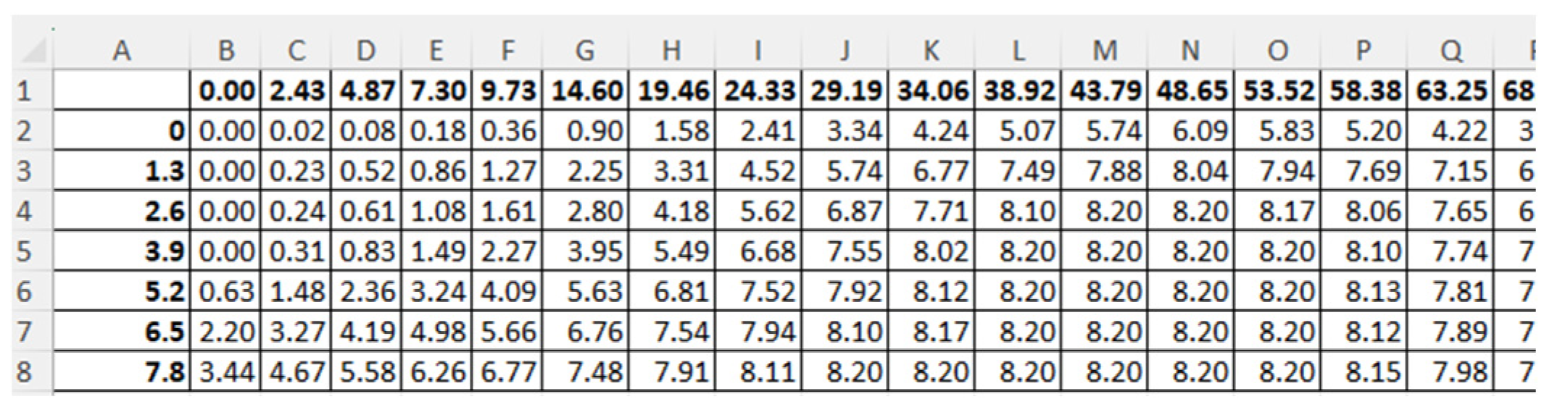
Figure 2.
Input Section.
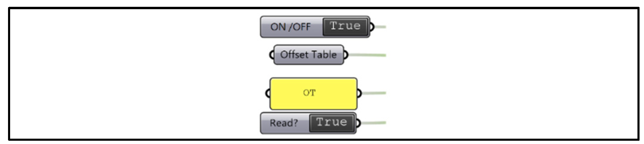
Figure 3.
Points from Offset Table.
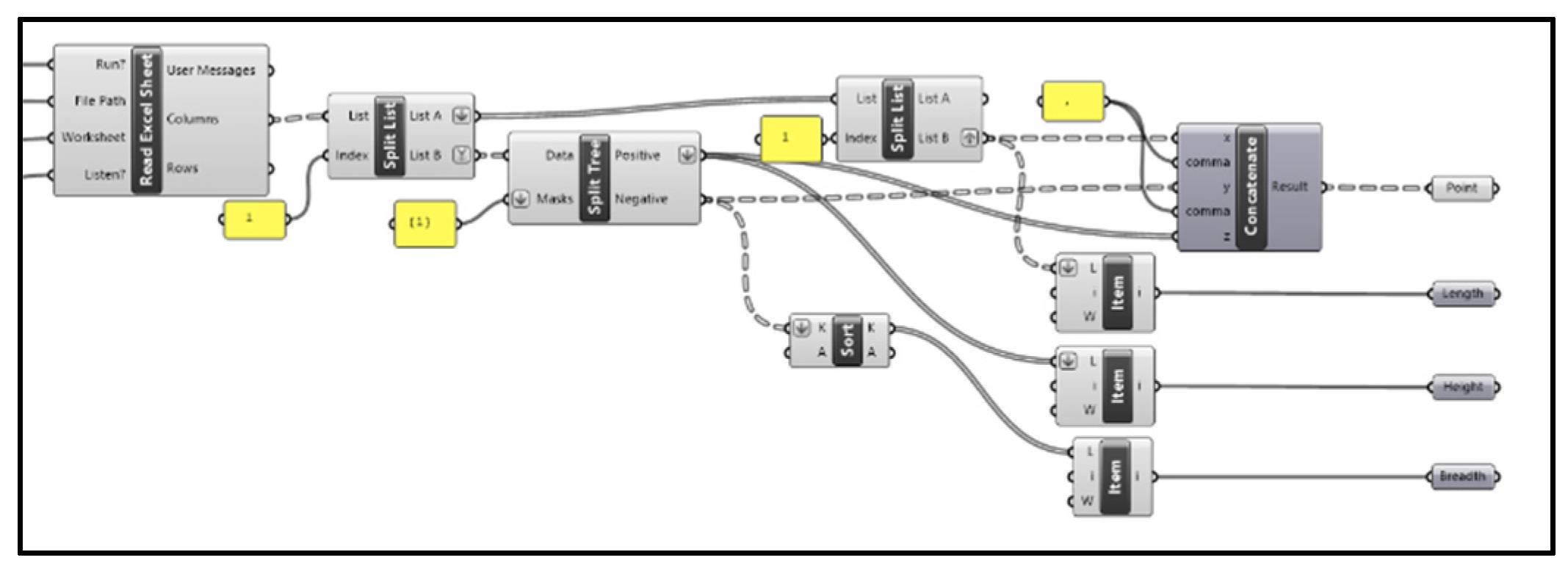
Figure 4.
Points from Offset Table.
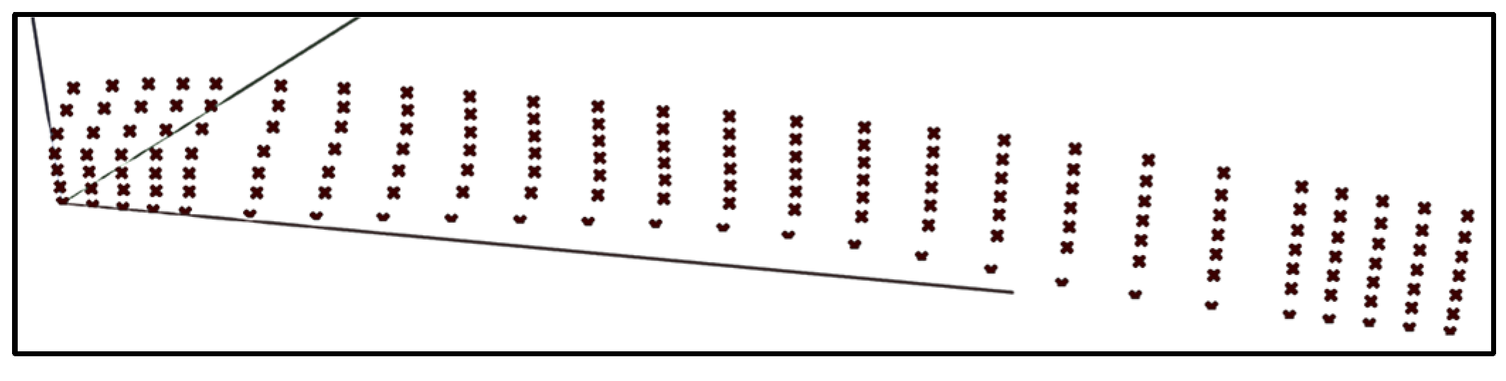
Figure 5.
Points from Offset Table.
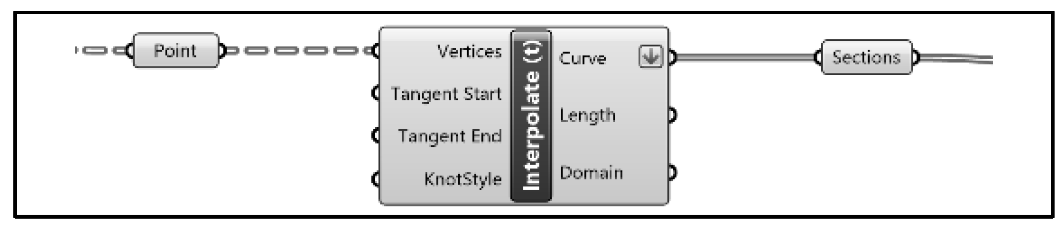
Figure 6.
Section Curves from Points.
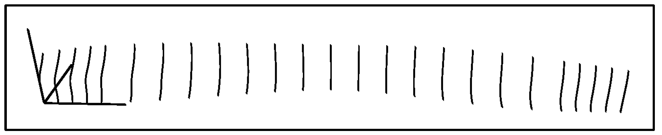
Figure 7.
Hull Generation Section.
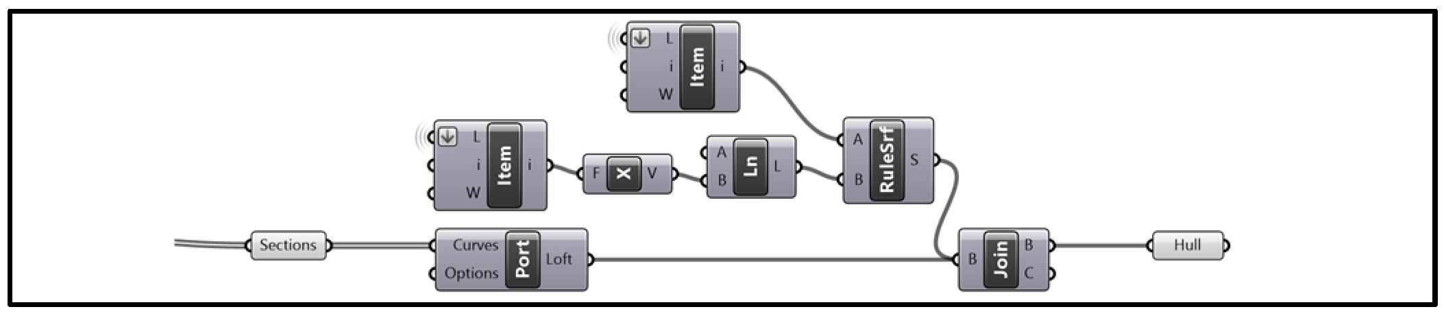
Figure 8.
Body Plan Generation Section.
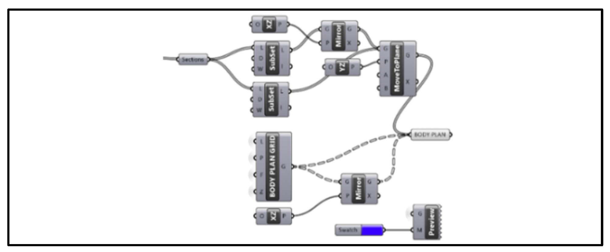
Figure 10.
Profile Generation Section.
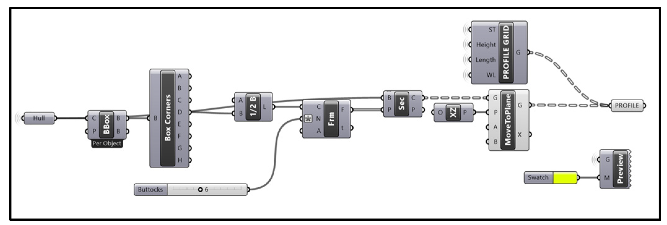
Figure 11.
Boundary Box.
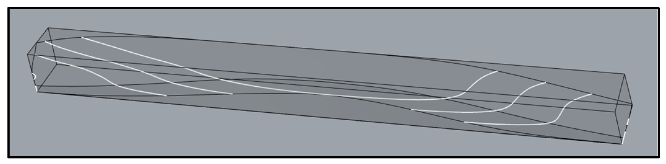
Figure 12.
Final Arranging Section.
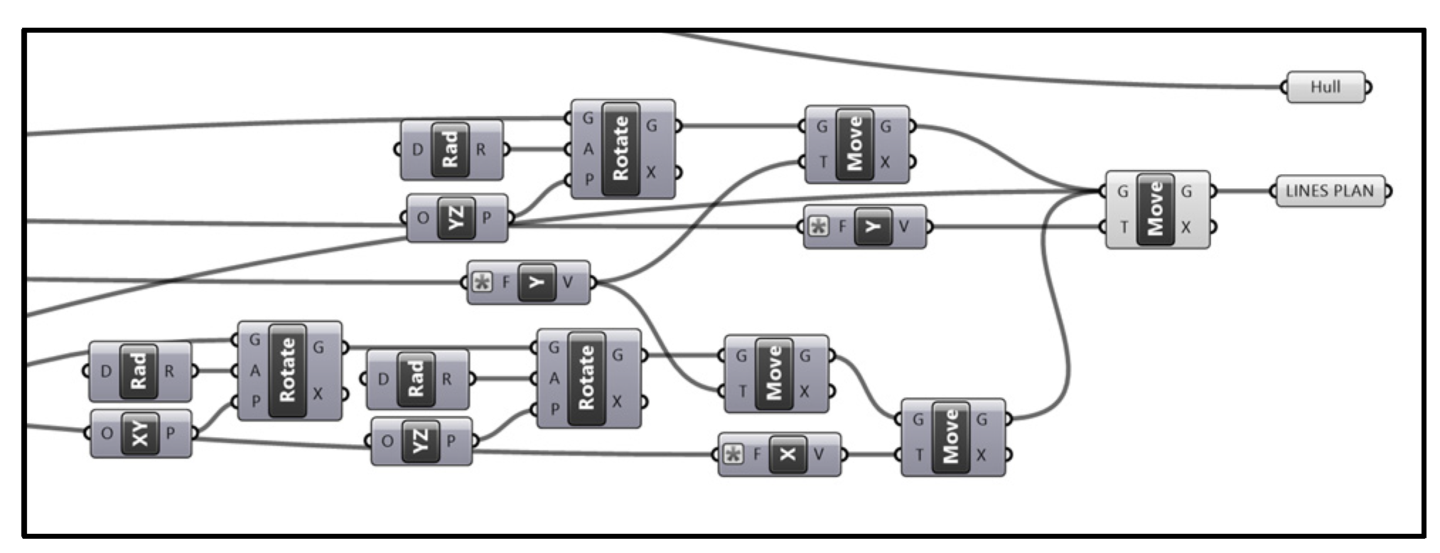
Figure 13.
Hull surface from section curves.
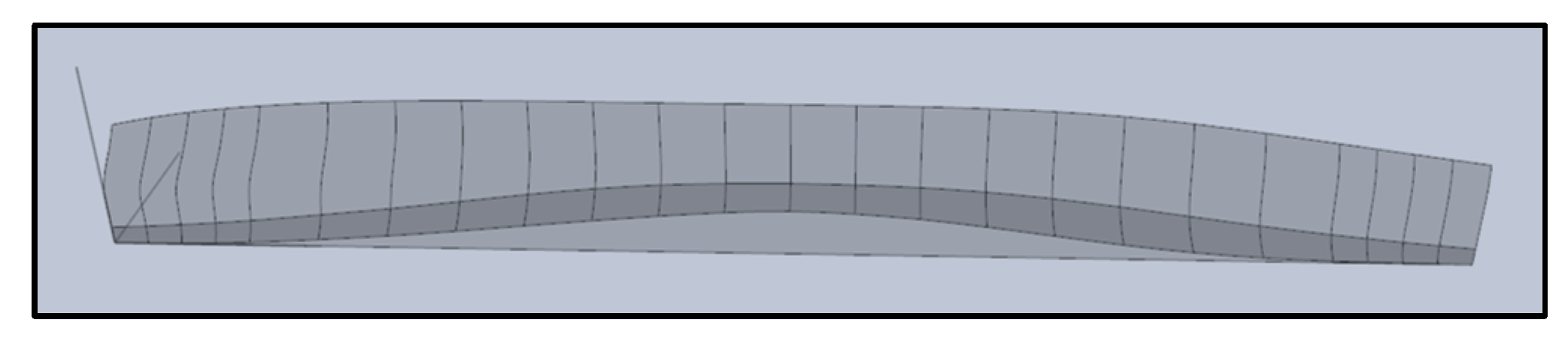
Figure 14.
Body Plan.
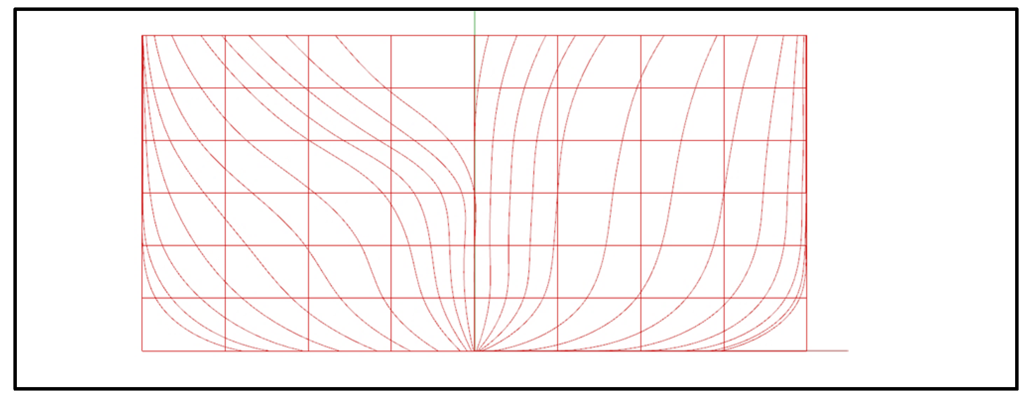
Figure 15.
Half Breadth Plan.
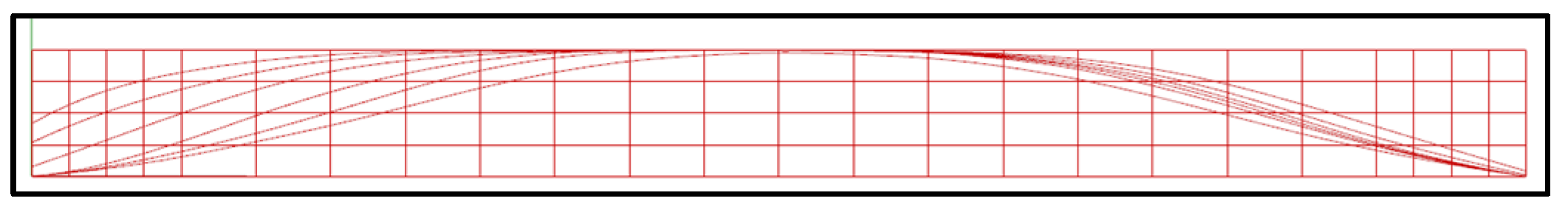
Figure 16.
Profile Plan.
Disclaimer/Publisher’s Note: The statements, opinions and data contained in all publications are solely those of the individual author(s) and contributor(s) and not of MDPI and/or the editor(s). MDPI and/or the editor(s) disclaim responsibility for any injury to people or property resulting from any ideas, methods, instructions or products referred to in the content. |
© 2024 by the authors. Licensee MDPI, Basel, Switzerland. This article is an open access article distributed under the terms and conditions of the Creative Commons Attribution (CC BY) license (http://creativecommons.org/licenses/by/4.0/).
Copyright: This open access article is published under a Creative Commons CC BY 4.0 license, which permit the free download, distribution, and reuse, provided that the author and preprint are cited in any reuse.


