
Submitted:
29 October 2024
Posted:
29 October 2024
You are already at the latest version
Abstract
This work presents an innovative tri-generation system for the simultaneous production of desalinated water, electrical energy, and cooling, aimed at addressing the growing challenges of water scarcity and climate change. The system integrates an 8-stage MSF process and a 6-effect MED process, along with an expander-generator that improves cycle efficiency by utilizing and reintroducing steam within the desalination stages. A parametric study was conducted using ASPEN PLUS to evaluate the system’s performance. The analysis showed that the system operates over a broader pressure and temperature range than conventional MED systems, from 28.3 to 0.8 kPa and from 68 to 4°C, thanks to a dual ejector-condensation process. In cogeneration mode, the system achieves a PR of 12.06 and an RR of 54%0.54, producing 67,219.2 L/day of desalinated water and reducing electrical consumption by 12.03%. In tri-generation mode, it achieves a PR of 17.81 and an RR of 0.80%, with a cooling capacity of 1225 kW (COP of 3.278), producing 99,273.6 L/day of desalinated water while reducing electrical consumption by 3.69%. This system offers an efficient solution to meet the growing water and energy needs of coastal communities, combining water desalination, energy production, and cooling in a single integrated process.
Keywords:
Barometric condensation
; Cooling
; Desalination
; Ejector
; Expander
; High vacuum
; MED
; MSF
; Power
Highlights:
The main contributions of the proposed technology are:
- Innovative trigenerative system simultaneously produces water, power and cooling.
- A new hybrid MSF/MED high vacuum thermal desalination system.
- The system operates in cogenerative or trigenerative mode based on seasonal needs.
- A novel ejector-condensation process increases brine concentration and desalination.
- The expander uses stage 1 steam, reinserting it at stage 8 to increase desalination.
Nomenclature:
| Symbols and abbreviations: | |||
| T | Temperature (°C) | EVA | Evaporator |
| P | Pressure (kPa) | EJ | Ejector condenser |
| Q | Heat transfer (kW) | PH | Preheater |
| m | Mass flow (kg/s) | MSF | Multi-stage distillation |
| h | Specific enthalpy (kJ/kg) | MED | Multiple effect distillation |
| v | Specific volume (m3) | RO | Reverse osmosis |
| s | Specific entropy (kJ/kg*K) | TBT | Top brine temperature (°C) |
| Ex | Exergy flow (kW) | BBT | Bottom brine temperature (°C) |
| W | Power (kW) | NaCl | Sodium chloride |
| Eff | Efficiency (%) | H2O | Water |
| RR | Recovery Ratio (-) | Temperature difference (°C) | |
| PR | Performance Ratio (-) | Pressure difference (°C) | |
| PRglobal | Performance Ratio global (-) | Subindex: | |
| COP | Coefficient Of Performance (-) | SW | Seawater |
| COPglobal | Coefficient Of Performance global (-) | SWT | Seawater tank |
| EC | Cobertura eléctrica (%) | PW | Producto water |
| SEEC | Specific Electrical Energy Consumption (kWh/m3) | i | Initial |
| STEC | Specific Thermal Energy Consumption (kWh/m3) | f | Final |
| SEC | Specific Energy Consumption (kWh/m3) | Br | Brine |
| GEN | Generator | mf | Motive fluid |
| HX | Heat Exchanger | sc | Suction chamber |
| Cond | Condenser | m | Mixer |
| SEP | Separator liquid-vapor | Number of streams | 1, 2, 3… |
| EV | Expansion valve | ||
| ST | Split flow | ||
| Mix | Mixer | ||
| EXP | Expander | ||
| P | Hydraulic pump | ||
| BC | Barometric column | ||
1. Introduction
Access to clean water, electricity and air conditioning is crucial for an adequate quality of life and sustainable development in marginalized communities. However, the enjoyment of these resources is threatened by current global challenges; the projected population increase to 9.3 billion by 2050 (Gude et al., 2010; Lee, 2011), drinking water scarcity and climate change. These issues cause the growing demand for electrical energy to satisfy the activation of air conditioning systems and the activation of water purification and/or desalination systems.
The outlook for water resource availability appears unfavorable. Despite the fact that 97% of the Earth's surface is covered by water (Chandrashekara & Yadav, 2017), inadequate management and uncontrolled exploitation are projected to result in a 40% global water deficit by 2030 (Ríos-Arriola et al., 2022). Concurrently, global energy demand and CO2 emissions have risen significantly (Ahmad & Zhang, 2020), largely due to the burning of fossil fuels for electricity generation, which powers conventional desalination and air conditioning systems. This contributes to climate change, with projections suggesting a global temperature rise of up to 1.5°C by 2100 (Betts et al., 2018). Additionally, the demand for air conditioning and refrigeration systems is expected to surge, from 4.4% in 2010 to 35% by 2050, potentially reaching 61% by 2100 (Davis & Gertler, 2015).
The development of systems that simultaneously provide multiple services—such as desalinated water, electricity, and air conditioning—offers a comprehensive solution to address these challenges. Energy-efficient operation of these systems leads to reductions in energy consumption, lower operating costs, and a more environmentally sustainable approach (Jana et al., 2017; Manesh & Onishi, 2021).
Desalination is now considered a key solution to global water scarcity. The two dominant technologies in the market are Reverse Osmosis (RO) and thermal desalination. RO systems account for approximately 70% of desalination plants worldwide, while Multiple Stage Flash (MSF) and Multiple Effect Distillation (MED) systems represent 21% and 7%, respectively (Abdelkareem et al., 2018). RO systems report an electrical energy consumption of 3.5 to 5.5 kWh per cubic meter (m³) of desalinated water produced. In contrast, MSF and MED technologies consume 1.5 to 3.5 kWh per m³ of electrical energy, in addition to 80 kWh of thermal energy (Hu & Chen, 2024). MSF and MED systems are more prevalent in regions where water contains high concentrations of dissolved solids, as they require less pretreatment of the feedwater and lower maintenance. Although RO systems consume up to 25% less energy than MSF and MED systems, the higher cost of pretreatment increases operational expenses, making RO less viable in these regions (La Torre et al., 2024).
Continuous development and innovation in MSF and MED technologies have demonstrated that reducing the top brine temperature (TBT) can mitigate corrosion issues and improve energy efficiency (Xue et al., 2018). These systems are referred to as LT-MED. Aly (1995) proposed a hybrid system that extends the temperature range from a TBT of 63°C to a bottom brine temperature (BBT) of 6°C, achieving a record-low BBT, cost reduction, and high performance with a Performance Ratio (PR) of 14.2 and a Gain Output Ratio (GOR) of 14.8. Further research by Thu et al. (2013), Shahzad et al. (2014), and Saren et al. (2022) explores hybridization of MED with adsorption desalination (AD) technologies, reducing BBT to 5°C, which increases production capacity and decreases specific energy consumption (SEC).
Research on the hybridization of MED desalination systems also explores integration with conventional or organic Rankine cycles (ORC), gas turbines, combined cycles, and the utilization of industrial waste heat. This approach aims to simultaneously produce potable water and electricity, thereby enhancing the efficiency and overall performance of these systems (Kronenberg, 1997; El-Nashar, 2001). ORCs are particularly noted for their ability to operate with low-capacity, low-temperature thermal energy sources by using low-boiling organic fluids (Garcia et al., 2018). Baccioli et al. (2018) proposed the use of waste heat recovery from industrial processes in ORC systems to power MED systems. Two configurations were analyzed, showing improved performance based on the second law of thermodynamics, with the first configuration proving more efficient by utilizing waste heat from the ORC to activate the MED system. Additionally, Aguilar-Jiménez et al. (2020) proposed the simultaneous operation of a MED and ORC system, demonstrating the technical feasibility of integrating the ORC evaporator with the first effect of the MED system. This integration increased both the water production capacity and the performance ratio (PR) of the MED/ORC system, with PR improvements of 8.8%, 13%, 17.65%, and 22% for electrical generation capacities of 20, 30, 40, and 50 kWelec, respectively.
The simultaneous production of desalinated water and cooling has been extensively studied. Hybridization proposals combining absorption heat pump cycles or cooling systems with MED desalination technologies are among the most commonly discussed in the literature (Aly, 1995; Gude & Nirmalakhandan, 2008; Abdulrahim & Darwish, 2014; Alelyani et al., 2017). Open absorption cycles integrated with desalination systems have been investigated by López-Zavala et al. (2019), who presented a LiBr-H2O absorption cooling system coupled with a single-effect flash desalination system, powered by solar thermal energy. Under design conditions, this system produces 838 L/day of desalinated water and has a cooling capacity of 23 kW. Additionally, they proposed a system integrating two subprocesses: a 14-effect FLASH/MED desalination unit and a LiBr-H2O absorption cooling system. This integrated energy and mass configuration results in a cooling capacity of 2,012 kW and a daily fresh water production of 73,569 liters, with a coefficient of performance (COP) of 6.15 and a PR of 6.63 (López-Zavala et al., 2019a). Similarly, in other work, López-Zavala et al. (2023) presented a 14-effect MED desalination system that uses an expansion valve in combination with a barometric ejector-condensation process for the simultaneous production of desalinated water and cooling. The system produces 74,736 L/day of fresh water, with a PR of 11.96 and a recovery ratio (RR) of 53%. Additionally, the cooling capacity reaches 2,043 kW, with a COP of 4.7. A global performance indicator, COPglobal, was proposed to evaluate the simultaneous production of fresh water and cooling, yielding a value of 9.325.
In a separate study, La Torre et al. (2024) integrated a 14-effect MED system with a barometric ejector-condensation process powered by solar thermal energy. This MED system operates under high vacuum, enhancing the pressure cascade compared to conventional MED systems, with temperature ranges from 68°C to 4°C and pressure ranges from 28.3 to 0.8 kPa. The high vacuum is achieved through the implementation of an ejector condenser that entrains and condenses steam at 4°C from the final effect. This configuration increases the desalination capacity, with a gain output ratio (GOR) improvement of 34.1% while reducing activation energy requirements by 25.4%. Additionally, the system achieves a recovery rate of 83%, representing a 120% increase compared to conventional MED systems.
The development and conceptualization of trigeneration systems for the simultaneous production of water, cooling/heating, and electric power have been widely reported in the literature, integrating various technologies to achieve this. For example, Maraver et al. (2012) presented a trigeneration system combining an organic Rankine cycle (ORC) powered by biomass combustion, a MED desalination system, and an absorption chiller cycle (ACC) for the production of electricity, potable water, and cooling. The analysis focused on the optimal distribution of heat generated by the ORC, with 40% allocated to the MED and ACC systems. The economic evaluation indicated a payback period of 4 to 20 years, depending on biomass resource costs. The study provides an optimistic outlook for the development of trigeneration systems based on renewable energy sources.
In the research by Ghaebi and Abbaspour (2017), a novel trigeneration system is proposed, integrating a MED desalination system with thermal vapor compression (TVC), an open-cycle gas turbine as the thermal source, a heat recovery steam generator (HRSG) operating at three pressure levels, and an absorption chiller cooling system (ACC) to produce desalinated water, cooling, and electric power. Heat from the combustion chamber is distributed through the HRSG, adjusting to the three pressure levels. The results show a thermal efficiency of 84.6% and an exergy efficiency of 57.57%.
Similarly, Abdelhay et al. (2020) presented a trigeneration system combining MED desalination, absorption cooling, and a power cycle activated by solar thermal energy. Their case study reported energy, exergy, and economic analysis results. The system’s production capacity is 4.1 MWelec, with 2,200 tons of cooling and a daily desalinated water production of 550 m³. The maximum total energy efficiency reaches 23.95%. Additionally, the specific cost of producing water is $1.245/m³, and the cooling cost is $0.003/kWhr.
Finally, this work presents a novel trigeneration system for the simultaneous production of water, cooling, and electric power, integrating a hybrid MSF/MED desalination and cooling subsystem. This system proposes the energetic and mass integration of two thermal desalination technologies: Multi-Stage Flash (MSF) with 8 stages and Multi-Effect Distillation (MED) with 6 effects. The technological contribution of this hybrid MSF/MED system lies in the extension of the operating range, with a top brine temperature (TBT) of 68°C and a bottom brine temperature (BBT) of 4°C in the sixth effect. The elimination of preheaters in the MED section allows all generated steam to be used for brine evaporation in the subsequent effects. Additionally, an electrical expansion-generation subsystem is integrated, which extracts a fraction of the mass flow from the first flash stage to generate electricity and meet the system’s electrical demand. The expanded steam is reinserted into the first effect of the MED section, increasing capacity and efficiency in both desalination and cooling. Furthermore, a condensation process using two barometric ejector condensers is employed instead of a conventional condenser, facilitating the extraction and adaptation of cold steam to produce desalinated water. The 4°C product water stream from the final MED effect is then used to generate a cooling effect, further enhancing system efficiency.
The proposed trigeneration system introduces an innovative technology that simultaneously produces desalinated water, cooling, and electrical power. Key innovations include the elimination of seawater preheaters in the MED section, improving overall system efficiency, and the integration of components that optimize energy use. This configuration provides a sustainable approach to meeting water, cooling, and electricity demands simultaneously.
2. System Description
Figure 1 shows the proposed trigeneration system, which consists of: 1) the hybrid MSF/MED thermal desalination and cooling subsystem, 2) the expansion and power generation subsystem, 3) the product water extraction and adaptation subsystem, and 4) the motive fluid cooling and brine dilution subsystem.
The operation of the hybrid MSF/MED thermal desalination and cooling subsystem begins when the seawater stream (18b) is drawn from the Seawater Tank and pressurized to the transport pressure (3 to 5 bar) by the hydraulic pump (PSW2), exiting as stream (22). This is introduced to the condenser (Cond8), where it absorbs the latent heat of condensation of the water vapor stream (51), preheating in the process. Then, the seawater stream (23) passes through the condensers of the subsequent stages, gradually increasing its temperature by acquiring the latent heat of condensation. This process continues until it reaches the maximum preheating temperature (65.5 °C) in the condenser (Cond1), exiting as the seawater stream (30). Subsequently, it is introduced to the expansion valve (EVgen), where a sudden pressure drop is performed until it reaches the saturation pressure of the TBT of the MSF/MED hybrid desalination subsystem. The stream (31) then enters the generator, where it receives both sensible and latent heat from the heat transfer fluid, which can come either from the solar collector field (stream 91) or from another thermal source. At the generator (GEN) outlet, the seawater stream (32) is in a two-phase (liquid-vapor) state and is introduced into a liquid-vapor separation chamber (SBr1), where it is divided into two streams: the concentrated brine (33) and the vapor (34).The concentrated brine stream (33) is directed to the second flash distillation stage, where it is introduced into the expansion valve (EVbr2). This valve suddenly reduces the pressure to the operating condition of stage 2, causing the flashing effect and steam generation, which leads to the concentrated brine stream (40) being in two phases. In turn, the mass flow of the water vapor stream (34) is divided by the splitter (ST2) which directs a fraction of the mass flow to the expander (stream 35) and another to the condenser (Cond1) (stream 37). The water vapor stream (37) is completely condensed in the condenser (Cond1) and then directed to the second flash distillation stage, where it is introduced into an expansion valve (EVPW2) to suddenly reduce its pressure to the operating condition of stage 2, which causes the flashing effect and vapor generation, resulting in a two-phase product water stream (39). The flashing vapors generated by the sudden pressure drop in the brine and product water of stage 2, are directed to their respective liquid-vapor separators (SPW2) and (SBr2), and then mixed in the mixer (Mix2) and subsequently condensed in the condenser (Cond2). The liquid streams of brine and product water are directed to the expansion valves of the next stage (EVBr3) and (EVPW3) to repeat this process successively until the eighth flash distillation stage.
At the end of the eighth flash distillation stage, multiple distillation effects (MED) are initiated. MED effects involve the use of heat exchangers for the evaporation or release of water from brine streams, using the water vapor generated in a previous effect. In addition, two liquid-vapor separators are used in each effect; one for the product water and one for the concentrated brine, as well as two expansion valves. It is important to note that, in the multiple distillation effects, due to their respective operating temperatures, seawater preheating equipment cannot be used, which is characteristic of high vacuum systems. The water vapor that activates the MED section is obtained from the sudden expansion of the brine and product water from stage eight of the MSF section, where the two-phase product water stream (49) enters the liquid-vapor separator (SPW8) and splits into two: a vapor stream (53) and a product water stream (54).
The two-phase concentrated brine stream (50) enters the liquid-vapor separator (SBr8), where it is divided into a vapor stream (57) and a brine stream (56). The streams (53) and (57) are mixed in the mixer (Mix8) and exit as stream (58), which will activate the first MED effect by releasing its latent heat and condensing in the heat exchanger (HX1), leaving as stream (60).
The concentrated brine stream (56) enters the expansion valve (EVBr9), where this valve suddenly reduces the pressure to the operating conditions of effect 1, in addition to causing a flashing effect and the generation of steam, this pressure reduction also leads to a decrease in the temperature of the stream (59). The two-phase stream (59) is directed to the heat exchanger (HX1) where it receives the latent heat of condensation from the steam streams (58). This heat exchange is possible since the aforementioned vapor stream (stream 58) are at a higher temperature than the two-phase brine stream (59), maintaining a minimum approach temperature of (∆Tmin =2.5°C) to carry out the heat transfer.
After exiting the condenser (Cond8), the product water stream (52) is directed to the mixer (Mix9) together with the product water streams (54) and (60), exiting as the product water stream (64). The product water stream (64) enters the expansion valve (EVPW9), where the pressure is suddenly reduced to effect 1 operating conditions. Simultaneously, the two-phase concentrated brine stream (61) is directed into the liquid-vapor separator (SBr9) and splits into two: a vapor stream (62) and a concentrated brine stream (63), where the latter enters the expansion valve (EVBr10), where the pressure is suddenly reduced to the operating conditions of effect 2. This process is repeated sequentially until the sixth multiple distillation effect is reached. The expansion and power generation subsystem begins by receiving a fraction of the vapor mass flow (stream 35) from the brine vapor-liquid separator (SBr1). The vapor stream (35) is then introduced into the volumetric expander, where it is drawn in and admitted into an expansion chamber. During this expansion process, the specific volume of the vapor increases (v36>v35), resulting in a simultaneous decrease of its pressure and temperature. The study of the expansion subsystem details two different modes of operation, characterized by working with different discharge pressures. In mode 1, the specific volume of the stream (35) is expanded to reach the operating pressure of MED effect 1, while in mode 2 it is expanded to reach the operating pressure of MED effect 6. Finally, the subsystem concludes with the insertion of the two-phase stream (36) in the liquid-product water vapor separator corresponding to the effect in which the outlet pressure of the volumetric expander coincides. By reinserting the two-phase stream (36), the vapor mass flow of that stream is combined with the vapor mass flow fraction of the two-phase stream (65) within the vapor-liquid separator (SPW9). This results in an increase in the mass flow in the vapor stream (67) and, consequently, in a higher heat transfer within the exchanger (HX2), which causes a higher generation of water as vapor from the two-phase sea brine stream (66). The described phenomenon is repeated successively in the subsequent MED effects, which increases the product water generation and cooling capacity of the proposed trigeneration system.
It is worth mentioning that the kinetic energy of the fluid (stream 35) is extracted by the expansion process and converted into mechanical work. This mechanical work is transferred to the rotary motion by the rotor to the shaft, then the shaft work is channeled to an electric generator for final conversion into usable electrical energy. The electrical energy produced by the expander is used for the self-consumption of the proposed system.
After leaving the sixth effect, the product water stream (84) is mixed in the mixer (Mix13) with the accumulated product water stream (82) from previous distillation stages and effects, resulting in the final product water stream (85). The latter passes to a 3-way valve (3WV), whose main function is to control the direction and/or division of the product water stream (85). It is important to note that the product water stream (88a) is used as the cooling fluid because it is in a saturated state, with a temperature of 4°C and a pressure of 0.81 kPa. The supply of the cooling fluid to the evaporator (stream 88a) is conditioned by the 3-way valve (3WV), allowing its partial or total use, depending on the cooling needs required by the user. On the other hand, the product water stream (88b) is directed to a barometric column (BC2) where its pressure is increased and discharged into the product water tank. The vapor streams (1) and (2) at low temperature and vacuum pressure are conducted to the ejector condenser (EJ1) for condensation by pressure increase.
Figure 1.
- Subsystem Diagram: MSF/MED Thermal Desalination and Cooling, Expansion and Power Generation.
Figure 1.
- Subsystem Diagram: MSF/MED Thermal Desalination and Cooling, Expansion and Power Generation.
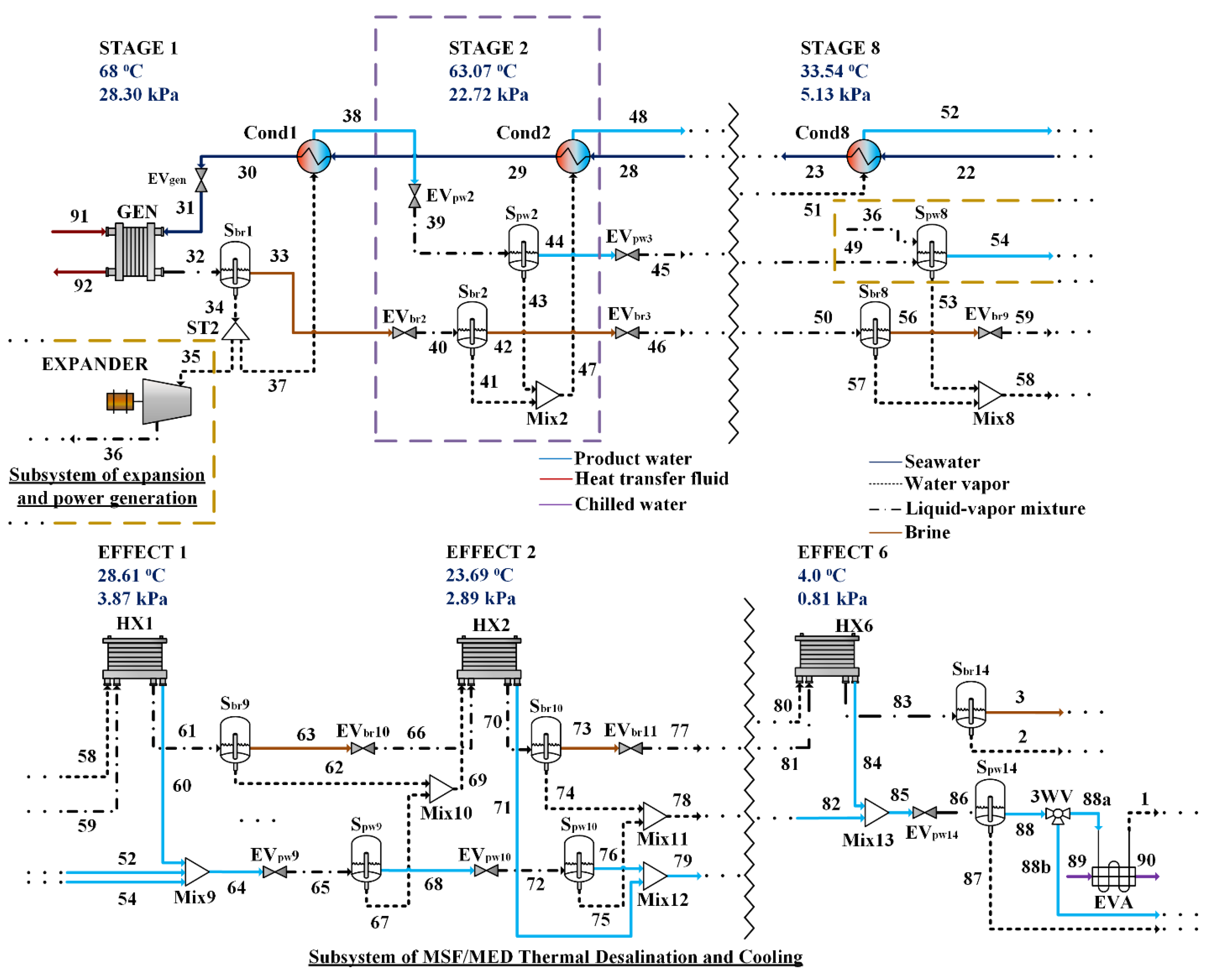
Figure 2 and Figure 3 show the product water extraction and adaptation subsystem, which includes two ejector condensers; one that cools the motive fluid with brine and the other with seawater. The principle of operation of the ejector condenser, like a conventional ejector, begins with the motive fluid entering the ejector (streams 9 and 14), where it passes through the convergent-divergent motive nozzle, increasing its velocity and reducing its pressure (streams 9sc and 14sc). This process draws and entrains the secondary fluid (6 and 93) into the ejector suction chamber. Subsequently, both streams enter the mixing chamber, where they combine, resulting in the transfer of momentum, heat, and mass, exiting as streams (9m and 14m).
Inside the mixing chamber of the ejector, a shock wave is produced due to the deceleration of the mixed stream, resulting in an increase in pressure and temperature of the mixture, all as a result of the transport phenomena mentioned above. Subsequently, the mixture of motive and suctioned fluid (also called primary and secondary) enters the diffuser, where, by increasing the cross-sectional area of the ejector, its velocity decreases, causing a pressure increase and thus achieving total condensation of the water vapor. Finally, the condensed mixture (10 and 15) is directed towards the barometric columns (BC1 and BC3) because it is under vacuum pressure, before being deposited in the product water storage tank at atmospheric pressure.
The ejectocondensation process causes a temperature increase in the mixed streams at the outlet of the ejector due to the transfer of condensation heat from the secondary fluid to the primary fluid. This increase in temperature causes energy accumulation in the product water storage tank, from which the motive fluid is extracted. To counteract the temperature increase, the heat exchangers (HXBrine) and (HXSW) are used in their respective condensation circuits. The heat exchanger (HXBrine) uses the concentrated brine stream (3) as a cold stream (4°C), which makes it possible to reduce the temperature of the motive fluid stream (9) to 9°C. On the other hand, the heat exchanger (HXSW) uses the seawater stream (19) as the cold stream (25°C), allowing a temperature of the motive fluid stream (14) of 28.5°C. The two-phase brine stream (4) is split into two in the vapor-liquid separator (SBr15). The concentrated brine stream (17) is directed to the barometric column (BC4), to increase its pressure and be subsequently deposited in the brine dissolution tank, where it joins with the seawater stream (20). The steam stream (5) enters the flow splitter (ST1) to control the steam mass flow to be condensed in both ejector condensers. The ejector condenser (EJ1) condenses the vapor stream (6), which consists of the sum of the vapors coming from the evaporator (1), the sixth effect (2) and the vapor stream (5b). On the other hand, the ejector condenser (EJ2) is in charge of condensing the remaining vapor (88) that was not introduced in the first ejector condenser.
2.1. Main Characteristics of the System:
- The proposed trigeneration system implements a hybrid thermal desalination technology, consisting of an 8-stage MSF process (with pressure ranges from 28.3 to 5.1 kPa) and a 6-effect MED process (with pressure ranges from 3.8 to 0.8 kPa), operating under high vacuum conditions.
- In the product water extraction and adaptation subsystem, it increases the production of product water by using the concentrated brine stream as a heat dissipating fluid in the first ejector-condensation circuit.
- Two two-phase ejectors at different operating temperatures are used in the motive fluid for the ejection-condensation process.
- The expansion-electrical generation subsystem increases the production of product water and cooling water by expanding the steam from stage 1 flash distillation and reintroducing it into effect 1 or 6 of multiple effect distillation.
- Since there is no temperature gradient, no preheaters are used in the MED section and all the steam generated in one effect is used in the next effect, which increases the production of product water.
- In the product water extraction and adequacy subsystem, the additional steam generated when brine is used to cool the motive fluid is condensed and controlled. This control is carried out in order to establish a limit in the steam generation to guarantee the correct operation of the ejector condensers and not to exceed the concentration limits of calcium sulfate (CaSO4).
3. Methodology
For the parametric study of the trigeneration system proposed in this work, the analysis focused on the technology integrating components such as heat exchangers, vapor-liquid separators, expansion valves, and an expander. An exhaustive literature review was conducted to identify the most appropriate simulation program for studying the operating behavior and design conditions of the system, thus establishing the production limits for water, cooling, and power.
3.1. Software Simulation Process
The evaluation of the technical feasibility of the proposal was carried out using Aspen Plus simulation software, which allows the development, operational analysis and economic evaluation of chemical and petrochemical processes. In addition, it has databases of thermochemical properties of substances and compounds that help in the calculations of the different thermodynamic states of the study streams. Its modular architecture allows the integral interaction between specialized blocks, such as heat exchangers, separators, etc., which facilitates the representation and simulation of thermodynamic processes and phenomena of interest for the operational study of the subsystems in this work. Figure 4 shows the general methodology diagram of the simulation process in Aspen Plus.
The simulation process of the proposed system starts with the execution of the thermodynamic properties calculations using the previously selected methods, being IAPWS-95 for water and Electrolyte for streams and modules working with seawater. These calculations are applied to the process streams and specific modules (HEAT X, PUMP, FLASH2, HEATER, FSPLIT, MIXER, VALVE, COMPR) to obtain detailed results. Then, we proceed to the configuration and execution of the simulation, where the interactions and behaviors of the trigeneration system are simulated under specific conditions. During the simulation process, convergence blocks including iterative variables are used. The results obtained from these variables are recorded and analyzed to evaluate the performance of the proposed system and validate its operation according to the established criteria.
Table 1 shows the names of the components represented, the Aspen Plus blocks used, the symbology and the general equations used in the construction of the system.
Table 2 presents the interconnection configuration between the blocks used for the representation of the subsystems of the proposed trigeneration system and their structure in the main flow page in Aspen Plus. The subsystems: hybrid MSF/MED thermal desalination and cooling, as well as the Expander-generator, are represented in the processes STAGE 1 and ACTIVATION SOURCE, STAGES 2 to 8, EFFECTS 1 to 5, and EFFECTS 6. On the other hand, the subsystems extraction and product water adaptation, and cooling of the motive fluid and brine dilution, are represented in the SUBSYSTEM C-ECB (Cooling-Ejector condenser Barometric) process.
3.2. System Parameters
In the operational study of the proposed trigeneration system, the parameters detailed in Table 3 were established and the seawater feed flow to the system was varied, as well as the activation heat supplied to the generator. The seawater feed flow is at 25°C and a concentration of 35,000 ppm of the compound NaCl is considered, which limits a seawater TBT of 68°C to avoid corrosion problems, as reported by Palenzuela et al. (2014).
3.3. Basic Assumptions
Simulation in Aspen Plus, particularly with recirculation streams, requires the initialization and definition of iterative variables, as outlined in the methodology diagram. These variables are used to iteratively solve the simulation process. When simulating the system’s operating behavior, the following basic assumptions are considered.
The following considerations were taken into account for the operational simulation study of the proposed system, both for the trigeneration and cogeneration modes:
- The technical feasibility and the behavior of the proposed MSF/MED system to the high vacuum in steady state is analyzed.
- The hybrid MSF/MED to high vacuum thermal desalination subsystem uses a TBT of 68°C and a BBT of 4°C.
- The heat exchange between streams considers a minimum approach temperature (∆Tmin) of 2.5°C. for stages and effects.
- A maximum seawater preheating temperature of T30=65.5 °C is established.
- An isentropic efficiency of 85 % of the hydraulic pumping equipment (PSW1, PSW2, PWP1, PWP2) is considered.
- An isentropic efficiency of 85% is considered in the expander (Expander).
- Expander discharge pressure is 5.129 kPa.
- All the condensed product water is used as refrigerant fluid, in trigeneration operation.
- The pressure drop in the equipment and piping is negligible.
- An exergy efficiency of 85% is considered in the ejector condenser (EJ1).
- An exergy efficiency of 28% is considered for the ejector condenser (EJ2).
- The properties of the equilibrium state: temperature of 25°C and absolute pressure of 1 atm.
3.4. System Energy Performance Indicators
The selected performance indicators evaluate in single, cogenerative and trigeneration production the system's products. The equations are defined based on the energy balance by the first law of thermodynamics.
The following indicators were used in the desalination performance evaluation: Recovery Ratio (RR), Performance Ratio (PR) and global Performance Ratio (PRglobal). The RR indicator (Eq. (1)) represents the fraction of seawater that is converted to desalinated water. To evaluate the thermal supply of the system, the PR indicator (Eq. (2)) was used, which describes the ratio between the latent heat of the product water and the thermal energy supplied. In addition, another indicator, the PRglobal (Eq. (3)), is proposed, which considers the thermal and electrical energy requirement supplied to the system (La Torre et al., 2024).
The cooling production performance of the system was analyzed using the Coefficient of performance (COP) indicator (Eq. (4)), which relates the cooling capacity of the system to the energy supply (thermal and/or electrical) required. The COPglobal equation (Eq. (5)) proposed by López-Zavala et al. (2023) was used to evaluate the performance of simultaneous desalination and cooling production.
The following indicators were used to study energy consumption: Electrical Coverage (EC), Specific Electrical Energy Consumption (SEEC), Specific Thermal Energy Consumption (STEC) and Specific Energy Consumption (SEC). Electrical Coverage describes the fraction of the system's electrical demand that is satisfied by the electrical generation of the expander (Eq. (6)).
SEEC and STEC are defined as the ratio between the amount of energy consumed (electrical or thermal) and the water capacity produced (Eq. (7)). The total specific energy consumption (SEC) is defined as the sum of the specific consumption of electrical and thermal energy (Eq. (8)).
The operating performance of the ejector condenser was evaluated with respect to the second law of thermodynamics. The exergy content of the currents entering the ejector was quantified using (Eq. (9)). On the other hand, for the thermodynamic feasibility study, (Eq. (10)) was used, which determines the exergetic destruction, likewise, for the calculation of the exergetic efficiency of the ejector condenser, (Eq. (11)) was used.
4. Validation of Simulation
The validation of the proposed trigenerative system was performed in two parts: 1) the double barometric ejectocondensation subprocess of the product water extraction and adaptation subsystem, and 2) thermal desalination subprocess concerning the MSF/MED subsystem to high vacuum. For the first part, the experimental work reported by Sağ et al., (2017) which corresponds to the study of exergy destruction of the components of an ejecto compression cooling system was used.
The proposed trigenerative system, like the work reported by Sağ et al. (2017), uses a liquid-vapor two-phase ejector in an ejector-compression cooling system. However, unlike the system proposed in this work, the author considers partial condensation at the ejector outlet as a design condition. Therefore, a comparison was made between the operating results of the experimental system and those obtained by simulation in Aspen Plus, with the objective of analyzing the operating performance and studying the partial condensation process in the two-phase ejector simulated in Aspen Plus.
As shown in Table 3, the average error of the results is less than 1.5%. When evaluating the operating performance of the system using the first law of thermodynamics, it is observed that the cooling capacity, compressor work and COP do not present errors greater than 0.5%. In addition, the operating performance of the two-phase ejector shows a maximum error of 1.829%, which demonstrates the feasibility of performing the ejector study in Aspen Plus.
The experimental study conducted by Sağ et al. (2017) on the exergy destruction of each component of the ejecto compression cooling system was used to compare the experimental results with those generated by Aspen Plus.
Table 4 shows the exergy destruction of each component of the ejection compression cooling system. The results show a total average error of 4.44%, highlighting the condenser as the component with the highest percentage of error, reaching 9.4%. In contrast, the ejector, which is the component of greatest interest, presents an error of 0.27%.
In the second part of the validation, the work presented by López-Zavala et al. (2023) was used. The desalination and cooling system with barometric ejector condenser that they describe shares similarities in the operating principles with the proposed MSF/MED to AV trigenerational system. Detailed information on the key parameters and considerations for the simulation of this system is presented in Table 5.
Table 6 shows the comparison of both simulations with respect to the desalination and cooling performance indicators, as well as the internal energy integration and heat transfer in the barometric condensation ejection subsystem. A maximum error of 0.638% is observed in the desalination and cooling performance indicators, a maximum error of 0.156% in the internal energy integration (preheating) and a maximum error of 2.8% in the barometric ejectocondensation subsystem section.
5. Analysis and Discussion Of Results
The parametric study presented in this work on the proposed trigeneration system is divided into two parts: the analysis of the system's behavior in cogeneration mode and its behavior in trigeneration mode.
5.1. Operational Study of the System in Cogeneration Mode
To operate in cogeneration mode, cooling production is eliminated in the MSF/MED hybrid thermal desalination subsystem under high vacuum conditions. This is achieved through the control of the 3-way valve (3WV), which diverts the condensed product water stream (88), preventing its entry into the evaporator (EVA) and thereby stopping the generation of the cooling effect in the system. The bypassed condensed product water stream (88b) is directed to the barometric column (BC2). The function of this column is to maintain the hydraulic vacuum seal of the system and increase the pressure to atmospheric levels, preparing the water for storage in the product water tank.
5.2. Operational Performance Results of the MSF/MED Thermal Desalination Subsystem under High Vacuum in Cogeneration/Trigeneration Modes
The amount of heat transferred in the stages of the MSF section and the effects of the MED section, along with the heat gained by the seawater to reach the maximum preheating temperature of 65.5°C, is presented in Figure 5, in relation to the variation in activation heat.
In the MSF section, heat transfer occurs only in the first stage due to the presence of the generator, which produces the steam necessary to reach the preheating temperature. The excess steam generated when operating above is used for the expander to produce electrical energy. As activation heat increases, the heat transferred for seawater preheating decreases, since the required heat is supplied by the mixture of flashed vapors from the product water and brine within the MSF. More steam generated in the generator reduces the brine flow to the second stage, decreasing the amount of flashed steam and, consequently, the heat transfer for preheating. This results in an increased steam flow to the condenser (Cond1) to achieve the maximum preheat temperature.
After the MSF section, the flashed vapors are no longer used to preheat the seawater due to the lack of a minimum temperature (ΔTmin=2.5°C) difference Instead, they are used to boil off the brine in the first effect of the MED section, gradually increasing heat transfer. Additionally, the reinsertion of steam expanded by the expander into the eighth stage of the MSF increases the mass of available steam, enhancing heat transfer in the MED section and creating a cascading effect throughout the other effects in the system.
The vapors generated by boiling and flashing in each stage or effect of the thermal desalination subsystem are shown in Figure 6. In the first stage of the MSF section, vapor is primarily produced through boiling to supply the condenser (Cond1) and reach the maximum preheating temperature (65.5°C). Subsequently, the desalination capacity decreases due to the flashing of water vapor caused by the pressure differential between stages.
By increasing the activation heat, more steam is generated in the generator. The excess steam produced, which is not required to feed the Condenser (Cond1) in stage 1, is used as a working fluid for the expander and is reintroduced in the eighth stage. The MED section is activated by utilizing the expanded steam from the expander, along with the vapors generated by the flashing of product water and the brine flow from the eighth stage. This creates a cascading effect, where the vapors generated by flashing are no longer used for preheating, but instead for boiling, allowing more water to be extracted from the brine stream as it passes through the effects. The increase in heat added to the generator leads to an increase in product water production capacity and, consequently, to a higher cooling capacity of the system in trigeneration operation.Principio del formulario
Figure 7 shows the production capacity of condensed water, water vapor directed to the expander and to Cond1, brine flow, and water vapor produced by flashing and boiling in effect 6. The internal variables in Figure 7 refer to the vapors generated in the first stage of the desalination subsystem, specifically the vapors from the condenser (Cond1) and the expander, as well as the brine flow at the outlet of the thermal desalination subsystem. The vapors (Cond1 and expander) tend to increase as more heat is added to the generator. This occurs because the water vapor directed to Cond1 supplies the remaining heat required to reach the maximum preheating temperature of the seawater, which had previously been preheated by the vapors generated through flashing in stages 2 to 8, which released their condensation heat for this purpose. As a result, a higher release of vapor from the brine leads to a reduced brine flow directed to the MSF section, causing an increase in Cond1 vapor. On the other hand, the steam flow to the expander increases because the water vapor originating from the generator, which is not used by condenser (Cond1), is directed to the expander.
The water vapor and condensed product water from effect 6 tend to increase, as shown in Figure 7. This occurs because the expanded steam at the expander outlet mixes with the steam from the eighth stage, and this mixture is used to boil the brine flow in the first heat exchanger of the MED section. This process gradually increases the desalination capacity as the steam flow from the expander rises, leading to enhanced heat exchange. Finally, the water vapor extracted from the brine in cogeneration or trigeneration operation modes tends to decrease as heat is added to the generator. This is due to the reduction in heat dissipated in the brine exchanger (HXBrine), as the heat transfer depends on the brine flow (stream 3) and the amount of steam to be condensed in the ejector condenser (EJ1).
5.3. Operational Performance Results of Subsystems: Product Water Extraction, Adequacy, and Cooling of the Motive Fluid in Cogeneration Mode.
Figure 8 shows the brine concentrations at the outlet of the thermal desalination subsystem and the heat exchanger (HXBrine). The brine concentration (Xppm@effect6) in the brine stream (3) at the MED section outlet increases due to the intensified boiling of water vapor in the generator and the higher steam flow to the expander, used in effect 1 (HX1). Similarly, the brine concentration (Xppm@HXBrine) also rises. This is attributed to the increased brine concentration at the MED section outlet and the dissipation of condensation heat from the motive fluid by the saturated brine stream (3). This process causes water boiling and a subsequent rise in concentration within the heat exchanger (HXBrine), with an average increase of 32.1% compared to the concentration at the outlet of effect 6, reaching a maximum of 225,087 ppm when operating at Q̇gen=350 kW. Furthermore, heat transfer in the heat exchanger (HXBrine) and secondary flow (FsEJ1) decrease due to the reduced brine flow, diminishing the capacity to remove condensation heat. This lowers the condensing capacity of the ejector condenser (EJ1) from 0.1758 to 0.0869 kg/s, redirecting the remaining cold vapor to the second ejector condenser (EJ2).
Cold vapors from the brine separator (SBr15) and effect 6 are used as secondary flows, while product water from a reservoir tank serves as the motive flow in the ejector condenser. Figure 9 shows a decrease in the motive flow (MfPW1) from 155 to 56.56 kg/s in ejector condenser (EJ1), and an increase in the motive flow (MfPW2) from 75 to 125 kg/s in (EJ2), along with an increase in the seawater flow (FSea) from 50 to 91.58 kg/s. This is due to the reduction in secondary flow (SfEJ1), driven by a decrease in brine flow, which reduces the demand for motive flow in (EJ1) and directs more steam to be condensed in (EJ2). The increase in secondary flow (SfEJ2) requires a higher motive flow, increasing the electrical demand of the hydraulic equipment (PPW2) by 10.77%, while the reduction in (SfEJ1) decreases the demand on (PPW1) by 15.33%. Heat exchange follows the trends of the motive flow: the heat exchanger (HXBrine) shows a reduction from 526.61 to 248.12 kW, while the heat exchanger (HXSea) increases from 277.57 to 509.47 kW
5.4. Overall Operating Performance Results in Cogenerative Mode.
As shown in Figure 10, increasing the activation heat boosts the amount of steam produced in the generator, which is used as the working fluid by the expander-generator. This leads to a rise in the expander's mechanical work, increasing power generation from 4.19 to 25.24 kWelec, thereby improving the system's electrical self-consumption coverage from 5.94% to 35.16%. The reinsertion of expanded steam into the eighth stage of the MSF section in the MSF/MED hybrid thermal desalination subsystem, operating under high vacuum, enhances steam boiling, which improves both desalination capacity and steam condensation in the product water extraction and treatment subsystem, significantly raising the system's electrical power demand.
Additionally, as depicted in Figure 10, the SEC indicator increases with the heat supplied to the generator, starting at 60.71 kWh/m³ and reaching 90.86 kWh/m³. This positions the proposed system above conventional MED and MSF desalination technologies in terms of SEC, as noted by Al-Karaghouli and Kazmerski (2013)."
As shown in Figure 11, the behavior of the PR and PRglobal indicators reveals a decrease in the system's desalination performance. This effect is observed because the system maintains constant product water production through the operation of the high-vacuum hybrid MSF/MED desalination subsystem and the motive fluid cooling and brine dilution subsystem, allowing the concentration process to reach a product water output of 1.212 kg/s. However, the increase in activation heat and the power allocated to the expander-generator's self-consumption do not enhance desalination performance, leading to a decline in efficiency as more heat is added to the system.
According to Section 5.1.1, an increase in activation heat correlates with a rise in water production capacity, escalating from 0.548 to 1.212 kg/s due to heightened seawater boiling (31). This phenomenon results in an increase in product water generation and RR from 38.2% to 84.4%.
As discussed in Section 5.1.3, this increase also contributes to higher electrical demand. However, the power input from the expander has a notable impact on desalination performance. The PR indicator diminishes from 25.51 to 8.05, representing a reduction of 68.4%, while the thermal power output (Q̇gen) increases to 350 kW. The PRglobal decreases from 10.64 to 6.68, indicating a reduction of 37.21%. This decrease is less pronounced than that of the PR, attributed to the electrical self-consumption of the expander.
The proposed system attains a PR of 25.51, which is 1.83 times higher than the value reported by Aguilar-Jiménez et al. (2020) for a MED/ORC cogenerative system. Additionally, the recovery rate of 38.2% to 84.4% is comparable to that observed in cooling desalination systems, which exhibit the highest recovery rates among phase-change desalination technologies (Salajeghe & Ameri, 2023; Rashad et al., 2023).
5.5. Operational Study of the System in Trigenerative Mode.
To operate the proposed system in trigeneration mode, the following modification is made within the hybrid MSF/MED thermal desalination and cooling subsystem. The condensed product water stream (88a), in a saturated state at 4°C, is used as a cooling fluid by being redirected through the 3-way valve (3VW) and introduced into the evaporator (EVA) to generate a cooling effect.
This trigeneration operation, involving the simultaneous production of product water, cooling, and electrical energy, has a direct impact on all subsystems, particularly in the cooling of the motive fluid and brine dilution. Power generation requires the production of additional steam in the generator, which is used as the working fluid to feed the expander. Subsequently, the expanded steam at the expander outlet is reinserted into the vapor-liquid separator (SPW9), increasing product water production and cooling capacity, as a greater mass flow of steam is available for boiling the concentrated brine stream (66) entering the heat exchanger (HX2). This leads to a higher concentration of brine at the outlet of the sixth effect. These factors result in a reduction of the maximum limit of the reinjected steam mass flow percentage and a decrease in the final concentration of the brine entering the brine dilution tank.
5.6. Operational Performance Results of Subsystems: Product Water Extraction, Adequacy, and Cooling of the Motive Fluid in Trigeneration Mode.
The brine concentrations, measured in parts per million (ppm), at the outlet of the thermal desalination subsystem and the concentrated brine stream at the outlet of the heat exchanger (HXBrine) are presented in Figure 12. The brine concentration (Xppm@effect6) represents the concentration in stream (3). The increase in this brine concentration is caused by two factors: the increased boiling of water vapor in the generator and the increased steam flow directed to the expander, which is then used for brine vapor boiling in the heat exchanger of effect 1 (HX1). Similarly, the brine concentration (Xppm@HXBrine) also rises, primarily due to the increase in brine concentration at the outlet of the MED section.
Additionally, the dissipation of condensation heat from the motive fluid by the saturated brine stream (stream 3) causes this stream to enter the saturation region, releasing water vapor and resulting in a higher concentration. The brine concentration at the outlet of the heat exchanger (HXBrine) shows an average increase of 203.01% compared to the concentration at the outlet of effect 6, exceeding the limiting concentration of 350.00 ppm when operating at Q̇gen=350 kW, with a reported concentration of 386.959 ppm.
Furthermore, heat transfer in the heat exchanger (HXBrine) and the secondary flow (FsEJ1) tend to decrease due to the reduction in brine flow, resulting in a diminished capacity to remove condensation heat. This reduces the condensing capacity of the ejector condenser (EJ1) from 0.1758 to 0.0869 kg/s, directing the remaining cold vapor to the second ejector condenser (EJ2).
The cold vapors from the brine separator (SBr15), evaporator, and effect 6 are used as secondary flows, while the product water, coming from a reservoir tank, is used as the motive flow in the corresponding ejector condenser. In Figure 9, a decrease in the motive flow (MfPW1) of the ejector condenser (EJ1) from 145.9 to 52.794 kg/s is observed, alongside an increase in the motive flow (MfPW2) of Ejector condenser (EJ1) from 272.8 to 817.05 kg/s, and an increase in the seawater flow (FSea) from 176.8 to 529.4 kg/s. This occurs because the motive flow is closely linked to the secondary flow; a decrease in the secondary flow indicates a lower amount of motive flow needed to ensure condensation.
The reduction in secondary flow (SfEJ1), as shown in Figure 13, is caused by the decrease in brine flow, which limits the amount of heat transferred in the heat exchanger (HXBrine). With an increase in activation heat, the steam flow to be condensed in the ejector condenser (EJ1) is reduced, transferring the remaining steam to the ejector condenser (EJ2) for condensation.
The increase in secondary flow (SfEJ2) requires a higher motive flow to achieve condensation, leading to an average increase of 17.86% in the electrical demand of the hydraulic equipment (PPW2). Conversely, the reduction in secondary flow (SfEJ1) results in an average decrease of 24.9% in the electrical demand of the hydraulic equipment (PPW1). Additionally, heat exchange follows the trends of both secondary and motive flows. As mentioned, condensing a larger amount of steam requires a higher motive flow, resulting in increased heat transfer in the heat exchanger to remove the condensation heat generated in the ejection-condensation process. The heat transfer in the heat exchanger (HXBrine) decreases from 1974.25 kW to 459.35 kW, while the heat transfer in the heat exchanger (HXSea) increases from 979.02 kW to 2954 kW.
5.7. Overall Operating Performance Results in Trigenerational Mode.
The power demand of the proposed system is primarily driven by the hydraulic pumping equipment in the product water extraction and adaptation subsystem. In trigeneration mode, the electrical demand increases due to the higher flow of motive fluid required for the condensation of the product water stream (88a) evaporated in the ejector condensers (EJ1 and EJ2).
The expander increases its electrical generation capacity as more heat is supplied, utilizing the additional steam as the working fluid. The reintroduction of the expanded vapor into the vapor-liquid separator (SPW9) enhances both water production and cooling, which subsequently raises the system's electrical demand. This behavior is shown in Figure 14, where both electrical demand and electrical coverage tend to increase.
This is because the electrical generation provided by the expander is less than the increase in the electrical demand of the system's hydraulic equipment, which is caused by the impact of the expanded steam on the MSF/MED thermal desalination subsystem operating at high vacuum, as well as the increase in cold steam mass flow from effect 6 and the evaporator. The system’s electrical demand increases to a maximum of 351.14 kW, but the power generated by the expander reduces the system’s overall electrical consumption by an average of 5.32%. Additionally, the self-consumption electrical coverage varies between 2.11% and 7.18%.
Although the product water capacity increases from 1,128 to 1,304 m³/day, this increase is not significant. The additional steam production in the generator leads to a rise in both water production and cooling capacity, increasing the power demand, which the expander fails to fully compensate. As a result, the specific energy consumption (SEC) indicator increases from 53.16 to 143.95 kWh/m³, reflecting higher energy consumption relative to the activation heat.
The system’s cooling capacity also increases with the additional heat supplied to the generator, rising from 665.07 to 2,320.3 kW, as shown in Figure 15. This is due to the reinsertion of expanded steam into the thermal desalination subsystem, which enhances product water capacity. The liquid product water at 4°C is used as the cooling fluid. After producing the cooling effect, the product water transitions to the vapor phase and is divided into two streams (ST2), fractionating the vapor mass flow for the proper operation of the ejector condensers (EJ1 and EJ2).
The maximum COP achieved is 3.43, which is 4.70 times higher than the COP of 0.73 reported by Gomri (2010) for single-effect absorption systems. Additionally, the COPglobal indicator proposed by López-Zavala et al. (2023) was 9.325, which is 1.643 times lower than the COP achieved by the proposed system, which reached 15.231.
The PR decreases from 52.51 to 8.66 as the heat input to the generator increases, while water production rises from 1.128 to 1.304 kg/s. The maximum PR of 52.51 is 3.76 times higher than that reported by Aguilar-Jiménez et al. (2020). The PRglobal, which accounts for both the thermal and electrical energy of the system, drops from 12.15 to 4.32, as the reduction in electrical demand from expander generation does not offset the increased heat input to the generator. The RR reaches a maximum of 86.7%, which is 2.22 times higher than the MED-HDH system reported by Tahir and Al-Ghamdi (2022). This suggests that future studies should investigate the technical feasibility of incorporating a crystallizer in the motive fluid cooling subsystem and brine dilution process.
5.8. Operational Performance Results of the Ejectocondensation Process
A study based on the second law of thermodynamics was conducted on the barometric ejectocondensation process, with the objective of determining the operating parameters of the motive pressure for the hydraulic pumping equipment (PPW1 and PPW2). The study assumed constant thermodynamic properties for the secondary fluid, with a pressure of 0.804 kPa, temperature of 4°C, and mass flow of 0.2167 kg/s. For the motive fluid, an initial mass flow rate of 130 kg/s was considered. However, as mentioned, the hydraulic pumping equipment features a flow variator that adjusts to ensure condensation.
Figure 17.
- Variation of exergy destroyed in the ejector condenser under different conditions of temperature and driving pressure.
Figure 17.
- Variation of exergy destroyed in the ejector condenser under different conditions of temperature and driving pressure.
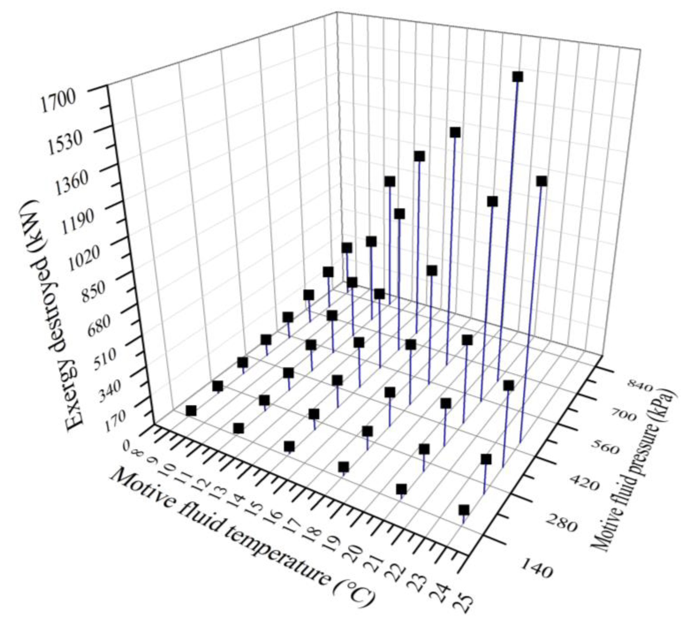
The exergy destruction results, shown in Figure 16, indicate that regardless of the temperature condition of the motive fluid, an increase in motive pressure at each temperature condition leads to an increase in exergy destruction. Additionally, it is observed that higher driving temperatures result in greater exergy destruction, suggesting a decrease in exergy efficiency. This occurs because increasing the driving pressure requires a higher motive flow to ensure complete condensation of the steam inside the ejector condenser. A higher motive flow in the ejector condenser leads to greater energy losses due to friction.
5.9. Operating Mode Comparison
The technological system developed in this work exhibits a distinctive operating behavior in terms of water production and electrical demand, depending on the operation mode.
In trigeneration mode, the water production capacity ranges from 1.128 to 1.304 kg/s, while in cogeneration mode it ranges from 0.548 to 1.212 kg/s, reflecting an average increase of 38.18% in trigeneration mode (Figure 18).
In trigeneration mode, the condensed water in the MED section is sent to the evaporator (EVA), where it changes phase to steam. This additional steam is directed to the ejector condenser (EJ1) for condensation, increasing the motive flow (FmPW1) and heat dissipation in the heat exchanger (HXBrine). The saturated brine (stream 3) is further heated and separated in the liquid-vapor separator (SBr15). Water vapor extraction in trigeneration mode varies from 0.791 to 0.1915 kg/s, while in cogeneration mode it ranges from 0.211 to 0.099 kg/s. This process reduces the final brine flow (stream 17), enhancing the potential for valuable mineral extraction and achieving zero liquid discharge.
After the parametric study, the following system design conditions were determined for both cogeneration and trigeneration modes. Table 7, Table 8, Table 9 and Table 10 provide the thermodynamic properties, operating characteristics, and energy evaluation of the system under the selected design conditions.

Table 8.
- Thermodynamic and operational characteristics of the MSF/MED at high vacuum trigenerative system.
Table 8.
- Thermodynamic and operational characteristics of the MSF/MED at high vacuum trigenerative system.
| No. Stage/Effects |
Pressure (kPa) |
Temperature (°C) |
Accumulated product water (kg/s) |
Brine concentration (ppm) |
Qcond (kW) |
Qeffects (kW) |
Seawater temperature (°C) |
| 1 | 28.3 | 68.00 | - | 36,467 | 38.65 | 150 | 65.5 |
| 2 | 22.73 | 63.08 | 0.0164 | 36,785.2 | 28.3 | - | 56.55 |
| 3 | 18.1 | 58.15 | 0.0281 | 37,104.2 | 28.34 | - | 52.05 |
| 4 | 14.32 | 53.23 | 0.0398 | 37,423.4 | 28.27 | - | 47.53 |
| 5 | 11.23 | 48.31 | 0.0512 | 37,743.6 | 28.24 | - | 43.03 |
| 6 | 8.72 | 43.38 | 0.0625 | 38,065.5 | 28.32 | - | 38.52 |
| 7 | 6.72 | 38.46 | 0.0737 | 38,387.9 | 28.24 | - | 34.01 |
| 8 | 5.13 | 33.54 | 0.0847 | 38,711.4 | 28.23 | - | 29.5 |
| 1 | 3.87 | 28.61 | 0.1364 | 40,245 | - | 94.13 | 25.0 |
| 2 | 2.89 | 23.69 | 0.1854 | 42,298.2 | - | 123.15 | 25.0 |
| 3 | 2.14 | 18.77 | 0.2455 | 45,014.5 | - | 152.01 | 25.0 |
| 4 | 1.56 | 13.85 | 0.3166 | 48,617 | - | 181.17 | 25.0 |
| 5 | 1.12 | 8.92 | 0.3986 | 53,451.1 | - | 210.72 | 25.0 |
| 6 | 0.79 | 4.00 | 0.4913 | 60,092 | - | 240.09 | 25.0 |
| HXBrine,cog | 0.79 | 4.00 | 0.1788 | 76,443 | - | 445.61 | - |
| HXBrine,trig | 0.79 | 4.00 | 0.5498 | 175,605 | - | 1371.1 | - |
| Totalcog | 236.63 | 1596.8 | |||||
| Totaltrig | 236.63 | 2422.5 |
Table 9.
- Energy evaluation of the proposed MSF/MED at high vacuum system under design conditions in cogenerative operation.
Table 9.
- Energy evaluation of the proposed MSF/MED at high vacuum system under design conditions in cogenerative operation.
| Components: | Energy balance |
Gains (kW) |
Losses (kW) |
Internal energy integration (kW) |
| Generator | 150 | |||
| HXBrine | 445.618 | |||
| HXSea | 361.69 | |||
| Condensers | 236.63 | |||
| Effects | 1051.39 | |||
| Expander | 8.568 | |||
| PPW1 | 32.43 | |||
| PPW2 | 33.26 | |||
| PSW1 | 7.505 | |||
| PSW2 | 0.176 | |||
| Streams: | ||||
| Seawater intake | -22,298.3 | |||
| Brine outlet | -10,002.7 | |||
| Product water outlet | -12,401.4 | |||
| Expander inlet steam | -550.98 | |||
| Expander outlet steam | -559.55 | |||
| Total: | -22,074.92 | -22,698.75 | 1,287.99 | |
| Product Water | 0.778 kg/s | |||
| PR | 12.062 | |||
| PRglobal | 8.179 | |||
| Recovery Ratio | 54.2% | |||
| Total power demand | 71.20 kW | |||
| E.C.Cog | 0.1203 | |||
| BC1 | 10.179 m | |||
| BC2 | 10.247 m | |||
| BC3 | 9.952 m | |||
| BC4 | 11.475 m | |||
Table 10.
- Energy evaluation of the proposed MSF/MED at high vacuum system under design conditions in trigenerative operation.
Table 10.
- Energy evaluation of the proposed MSF/MED at high vacuum system under design conditions in trigenerative operation.
| Components: | Energy balance |
Gains (kW) |
Losses (kW) |
Internal energy integration (kW) |
| Generator | 150 | |||
| Evaporator | 1224.32 | |||
| HXBrine | 1371.12 | |||
| HXSea | 1640.41 | |||
| Condensers | 236.63 | |||
| Effects | 1051.39 | |||
| Expander | 8.568 | |||
| PPW1 | 45.29 | |||
| PPW2 | 152.32 | |||
| PSW1 | 34.24 | |||
| PSW2 | 0.176 | |||
| Streams: | ||||
| Seawater intake | -22,298.3 | |||
| Brine outlet | -4,079.88 | |||
| Product water outlet | -18,258 | |||
| Expander inlet steam | -550.98 | |||
| Expander outlet steam | -559.55 | |||
| Evaporator coolant inlet | -7,843.97 | |||
| Evaporator refrigerant fluid outlet | -6,619.65 | |||
| Total: | -27,311.604 | -28,272.28 | 1288.02 | |
| Product water | 1.149 kg/s | |||
| PR | 17.81 | |||
| PRglobal | 6.995 | |||
| Recovery ratio | 80.06% | |||
| COP | 3.278 | |||
| COPglobal | 10.435 | |||
| Total power demand | 231.983 kW | |||
| E.C.Trig | 0.0369 | |||
| BC1 | 10.185 m | |||
| BC2 | - | |||
| BC3 | 9.952 m | |||
| BC4 | 13.069 m | |||
Table 11.
- Ejector condenser design conditions.
| Eyectocondenser | Parameters | Units | Motive fluid | Secondary fluid | Ejector condenser output |
| EJ1 | Temperature | °C | 9 | 4 | 12.19 |
| Pressure | kPa | 350 | 0.79 | 1.5 | |
| Mass flow | kg/s | 102.236 | 0.525 | 102.761 | |
| EJ2 | Temperature | °C | 28.5 | 4 | 29.38 |
| Pressure | kPa | 400 | 0.79 | 4.10 | |
| Mass flow | kg/s | 457.192 | 0.623 | 457.815 |
6. Conclusion
This work presents an innovative trigeneration desalination system that achieves higher efficiency by expanding the operating ranges of a desalination system and incorporating a dual barometric ejector-condensation process. This approach allows the generation of both cooling and electrical power from desalinated water, significantly increasing the system’s capacity and efficiency. The thermal desalination hybrid subsystem, composed of an 8-stage MSF process and a 6-effect MED process, together with the ejector condenser system, operates over a wider pressure and temperature range than conventional MED systems (from 28.3 to 0.8 kPa and from 68 to 4°C, respectively). Additionally, the system’s energy integration eliminates the need for additional preheaters in the MED section, maximizing the use of the condensers in the MSF section.
The parametric study results show that, with an activation thermal power of 150 kW, the system in cogeneration mode achieves a PR of 12.06 and an RR of 54%, producing 67,219.2 L/day of desalinated water, while electrical generation reduces the system’s electrical consumption by 12.03%. In trigeneration mode, the system achieves a PR of 17.81 and an RR of 80%, reaching a cooling capacity of 1225 kW with a COP of 3.278, producing 99,273.6 L/day of desalinated water, and reducing electrical consumption by 3.69%.
The sensitivity study on the ejector condensers, based on the second law of thermodynamics, demonstrated that the system can operate over a wide range of operating conditions. This allows for the condensation of cold steam at 4°C and a pressure of 0.8 kPa, coming from the MSF/MED thermal desalination subsystem and the motive fluid cooling and brine dilution subsystem. The operational parameters of the hydraulic pumping equipment (PPW1 and PPW2) were found to be key to the exergy efficiency of the ejector-condensation processes.
This study establishes a new paradigm for the development of high-vacuum MSF/MED tri-generation desalination systems that operate over a wider cascading pressure and temperature range. Not only does it increase desalination capacity and efficiency, but it also generates electrical energy and improves cooling production, providing an efficient solution to the growing water and energy demands in coastal communities. Future studies could focus on optimizing the integration of crystallizers for the extraction of valuable minerals and on studying a post-treatment process for the concentrated brine that exits the system as a final product, leveraging the system’s improved conditions.
7. Credit Authorship Contribution Statement
F.J. Caballero-Talamantes: Writing – review & editing, Writing – original draft, Visualization, Validation, Supervision, Software, Resources, Project administration, Methodology, Investigation, Funding acquisition, Formal analysis, Data curation, Conceptualization.
N. Velázquez-Limón: Writing – review & editing, Conceptualization.
J.A. Aguilar-Jiménez: Writing – review & editing, Formal analysis, Conceptualization, Project administration.
C.A. Casares-De la Torre: Writing – review & editing, Data curation, Formal analysis
R. López-Zavala: Validation, Formal analysis.
J. Ríos-Arriola: Writing – review & editing.
S. Islas-Pereda: Writing – review & editing.
8. Declaration of Competing Interest
The authors declare that they have no known competing financial interests or personal relationships that could have appeared to influence the work reported in this paper.
9. Acknowledgement
The authors would like to acknowledge “23a Convocatoria Interna UABC” grant number (111/6/C/19/23) and “Consejo Nacional de Humanidades Ciencias y Tecnologías (CONAHCYT)” for the scholarship granted to Francisco Javier Caballero Talamantes (CVU 1198440) to carry out his Master’s studies in Engineering.
References
- Abdelhay, A.; Fath, H.; Nada, S. (2020). Solar driven polygeneration system for power, desalination and cooling. Energy, 1173. [Google Scholar] [CrossRef]
- Abdelkareem, M.A.; Assad, M.E.H.; Sayed, E.T.; Soudan, B. (2017). Recent progress in the use of renewable energy sources to power water desalination plants. Desalination. [CrossRef]
- Abdulrahim, H.K.; Darwish, M.A. (2014). Thermal desalination and air conditioning using absorption cycle. Desalination And Water Treatment, 3310. [Google Scholar] [CrossRef]
- Aguilar-Jiménez, J.; Velázquez, N.; López-Zavala, R.; Beltrán, R.; Hernández-Callejo, L.; González-Uribe, L.; Alonso-Gómez, V. (2019). Low-temperature multiple-effect desalination/organic Rankine cycle system with a novel integration for fresh water and electrical energy production. Desalination, 1142. [Google Scholar] [CrossRef]
- Ahmad, T.; Zhang, D. (2020). A critical review of comparative global historical energy consumption and future demand: The story told so far. Energy Reports, 1991. [Google Scholar] [CrossRef]
- Alelyani, S.M.; Fette, N.W.; Stechel, E.B.; Doron, P.; Phelan, P.E. (2017). Techno-economic analysis of combined ammonia-water absorption refrigeration and desalination. Energy Conversion And Management. [CrossRef]
- Al-Karaghouli, A.; Kazmerski, L.L. (2013). Energy consumption and water production cost of conventional and renewable-energy-powered desalination processes. Renewable And Sustainable Energy Reviews. [CrossRef]
- Aly, S. (1995). A study of a new thermal vapor compression/multi-effect stack (TVC/MES) low temperature distillation system. Desalination. [CrossRef]
- Baccioli, A.; Antonelli, M.; Desideri, U.; Grossi, A. (2018). Thermodynamic and economic analysis of the integration of Organic Rankine Cycle and Multi-Effect Distillation in waste-heat recovery applications. Energy. [CrossRef]
- Betts, R.A.; Alfieri, L.; Bradshaw, C.; Caesar, J.; Feyen, L.; Friedlingstein, P.; Gohar, L.; Koutroulis, A.; Lewis, K.; Morfopoulos, C.; Papadimitriou, L.; Richardson, K.J.; Tsanis, I.; Wyser, K. (2018). Changes in climate extremes, fresh water availability and vulnerability to food insecurity projected at 1.5°C and 2°C global warming with a higher-resolution global climate model. Philosophical Transactions Of The Royal Society A Mathematical Physical And Engineering Sciences, 2016. [Google Scholar] [CrossRef]
- Davis, L.W.; Gertler, P.J. (2015). Contribution of air conditioning adoption to future energy use under global warming. Proceedings Of The National Academy Of Sciences, 5962. [Google Scholar] [CrossRef]
- El-Nashar, A.M. (2001). Cogeneration for power and desalination — state of the art review. Desalination. [CrossRef]
- Ghaebi, H.; Abbaspour, G. (2017). Thermoeconomic analysis of an integrated multi-effect desalination thermal vapor compression (MED-TVC) system with a trigeneration system using triple-pressure HRSG. Heat And Mass Transfer, 1337. [Google Scholar] [CrossRef]
- Gomri, R. (2010). Investigation of the potential of application of single effect and multiple effect absorption cooling systems. Energy Conversion And Management, 1629. [Google Scholar] [CrossRef]
- Gude, V.G.; Nirmalakhandan, N. (2008). Combined desalination and solar-assisted air-conditioning system. Energy Conversion And Management, 3326. [Google Scholar] [CrossRef]
- Gude, V.G.; Nirmalakhandan, N.; Deng, S. (2010). Renewable and sustainable approaches for desalination. Renewable And Sustainable Energy Reviews, 2641. [Google Scholar] [CrossRef]
- Hu, Z.; Chen, Y. (2024). Advancements in sustainable desalination with ocean thermal energy: A review. Desalination, 1177. [Google Scholar] [CrossRef]
- Jana, K.; Ray, A.; Majoumerd, M.M.; Assadi, M.; De, S. (2017). Polygeneration as a future sustainable energy solution – A comprehensive review. Applied Energy. [CrossRef]
- Kronenberg, G. (1997). Cogeneration with the LT-MED desalination process. Desalination. [CrossRef]
- La Torre, C.C.; Velázquez-Limón, N.; López-Zavala, R.; Ríos-Arriola, J.; Islas-Pereda, S.; Dévora-Isiordia, G.; Aguilar-Jiménez, J. (2024). High vacuum multiple effect desalination system with barometric ejector condensation. Desalination, 1178. [Google Scholar] [CrossRef]
- Lee, R. (2011). The Outlook for Population Growth. Science. [CrossRef]
- López-Zavala, R.; Velázquez, N.; González-Uribe, L.; Quezada-Espinoza, K.; Aguilar-Jiménez, J.; Islas, S.; Nakasima-López, M.; González, E. (2019). Absorption cooling and desalination system with a novel internal energetic and mass integration that increases capacity and efficiency. Desalination, 1141. [Google Scholar] [CrossRef]
- López-Zavala, R.; Velázquez-Limón, N.; González-Uribe, L.; Aguilar-Jiménez, J.; Alvarez-Mancilla, J.; Acuña, A.; Islas, S. (2019). A novel LiBr/H2O absorption cooling and desalination system with three pressure levels. International Journal Of Refrigeration. [CrossRef]
- López-Zavala, R.; Velázquez-Limón, N.; Ojeda-Benítez, S.; Nakasima-López, M.; Lara, F.; Aguilar-Jiménez, J.; Santillán-Soto, N.; Islas, S. (2023). Novel desalination system that uses product water to generate cooling through a barometric ejector-condenser. Energy, 1275. [Google Scholar] [CrossRef]
- M, C.; Yadav, A. (2016). Water desalination system using solar heat: A review. Renewable And Sustainable Energy Reviews, 1330. [Google Scholar] [CrossRef]
- Manesh, M.H. K.; Onishi, V.C. (2021). Energy, Exergy, and Thermo-Economic Analysis of Renewable Energy-Driven Polygeneration Systems for Sustainable Desalination. Processes. [CrossRef]
- Maraver, D.; Uche, J.; Royo, J. (2011). Assessment of high temperature organic Rankine cycle engine for polygeneration with MED desalination: A preliminary approach. Energy Conversion And Management. [CrossRef]
- Ng, K.C.; Thu, K.; Kim, Y.; Chakraborty, A.; Amy, G. (2012). Adsorption desalination: An emerging low-cost thermal desalination method. Desalination. [CrossRef]
- Palenzuela, P.; Hassan, A.S.; Zaragoza, G.; Alarcón-Padilla, D. (2014). Steady state model for multi-effect distillation case study: Plataforma Solar de Almería MED pilot plant. Desalination. [CrossRef]
- Pouyfaucon, A.B.; García-Rodríguez, L. (2018). Solar thermal-powered desalination: A viable solution for a potential market. Desalination. [CrossRef]
- Rashad, M.I.; Faiad, H.A.; Ghonim, A.T.; Ahmed, S.; Farahat, M.A. (2023). Single-stage freezing desalination study with slurry pressing piston and enhanced vacuum for brine extraction. Desalination, 1169. [Google Scholar] [CrossRef]
- Ríos-Arriola, J.; Velázquez, N.; Aguilar-Jiménez, J.A.; Dévora-Isiordia, G.E.; La Torre, C.A. C.; Corona-Sánchez, J.A.; Islas, S. (2022). State of the Art of Desalination in Mexico. Energies, 8434. [Google Scholar] [CrossRef]
- Sağ, N.B.; Ersoy, H.K.; Hepbasli, A. (2017). An experimental investigation on exergy analysis of an ejector expansion refrigeration system. International Journal Of Exergy. [CrossRef]
- Salajeghe, M.; Ameri, M. (2023). Evaluation of the energy consumption of hybrid desalination RO-MED-FD to reduce rejected brine. Environmental Progress & Sustainable Energy. [CrossRef]
- Saren, S.; Mitra, S.; Miyazaki, T.; Ng, K.C.; Thu, K. (2021). A novel hybrid adsorption heat transformer – multi-effect distillation (AHT-MED) system for improved performance and waste heat upgrade. Applied Energy, 1177. [Google Scholar] [CrossRef]
- Shahzad, M.W.; Ng, K.C.; Thu, K.; Saha, B.B.; Chun, W.G. (2014). Multi effect desalination and adsorption desalination (MEDAD): A hybrid desalination method. Applied Thermal Engineering. [CrossRef]
- Tahir, F.; Al-Ghamdi, S.G. (2022). Integrated MED and HDH desalination systems for an energy-efficient zero liquid discharge (ZLD) system. Energy Reports. [CrossRef]
- Xue, Y.; Du, X.; Ge, Z.; Yang, L. (2018). Study on multi-effect distillation of seawater with low-grade heat utilization of thermal power generating unit. Applied Thermal Engineering. [CrossRef]
Figure 2.
- Subsystem diagrams: the product water extraction and adaptation, and the motive fluid cooling and brine dilution.
Figure 2.
- Subsystem diagrams: the product water extraction and adaptation, and the motive fluid cooling and brine dilution.
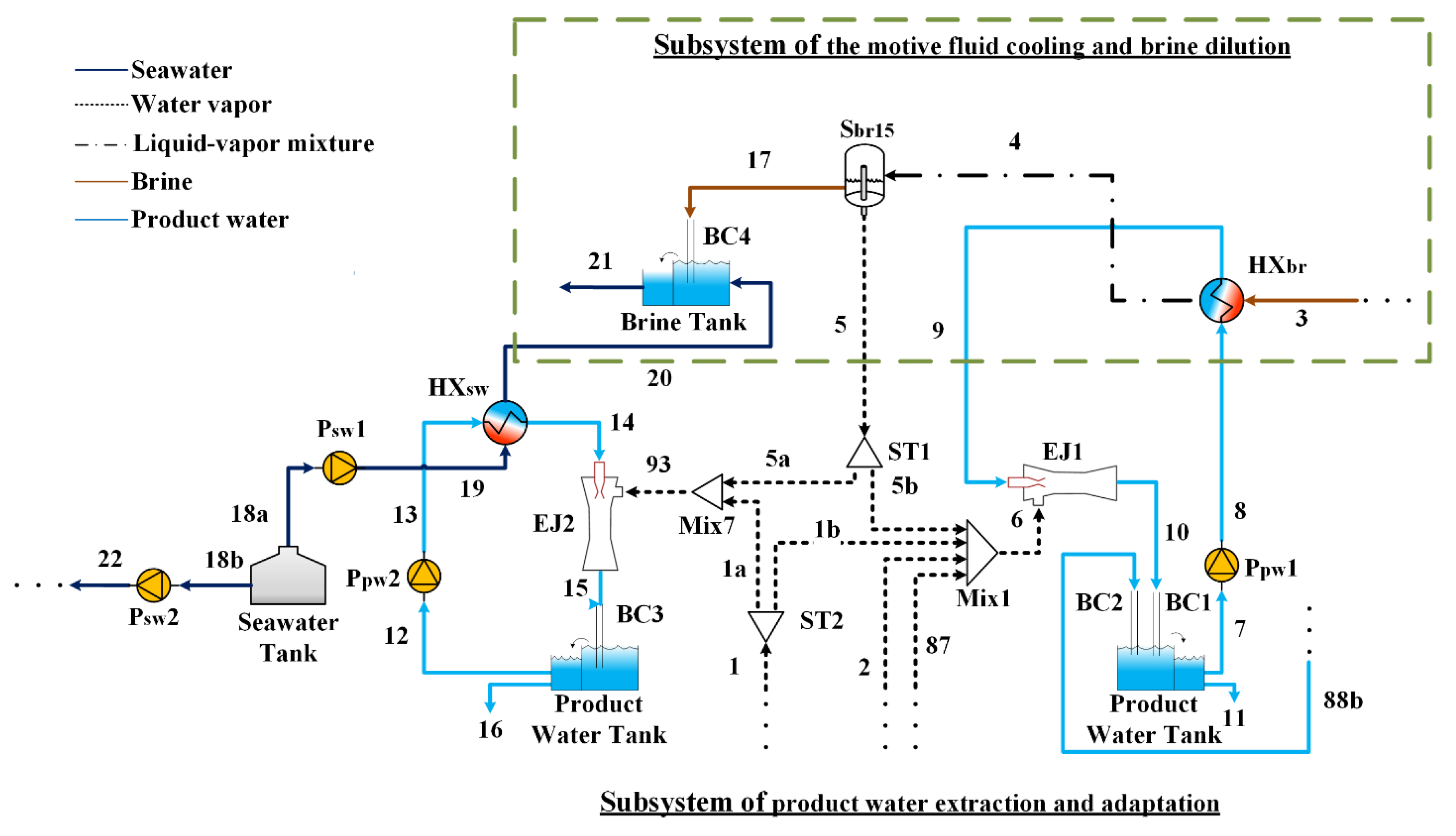
Figure 3.
- P-h diagram of the Product Water Extraction and Adaptation Subsystem.
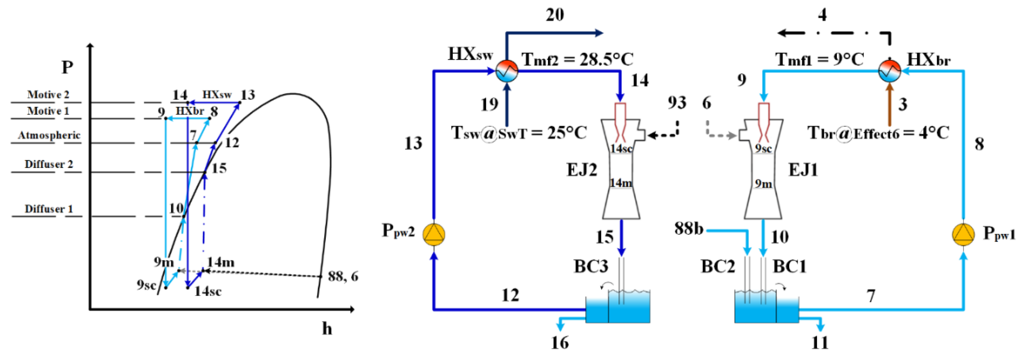
Figure 4.
- General methodology diagram and the simulation process in Aspen Plus.
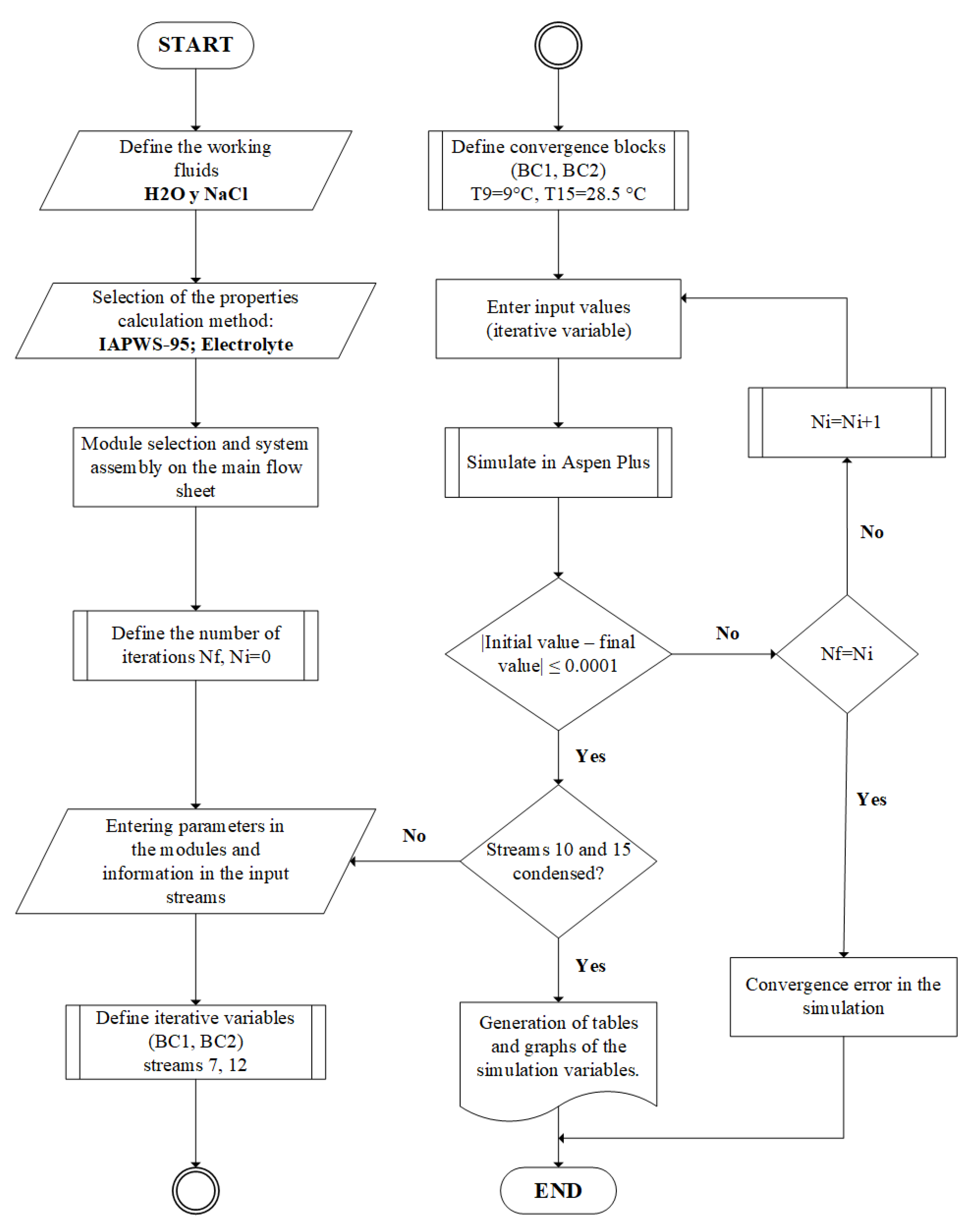
Figure 5.
- Preheat/heat transferred in stages/effects within the MSF/MED HV thermal desalination system.
Figure 5.
- Preheat/heat transferred in stages/effects within the MSF/MED HV thermal desalination system.
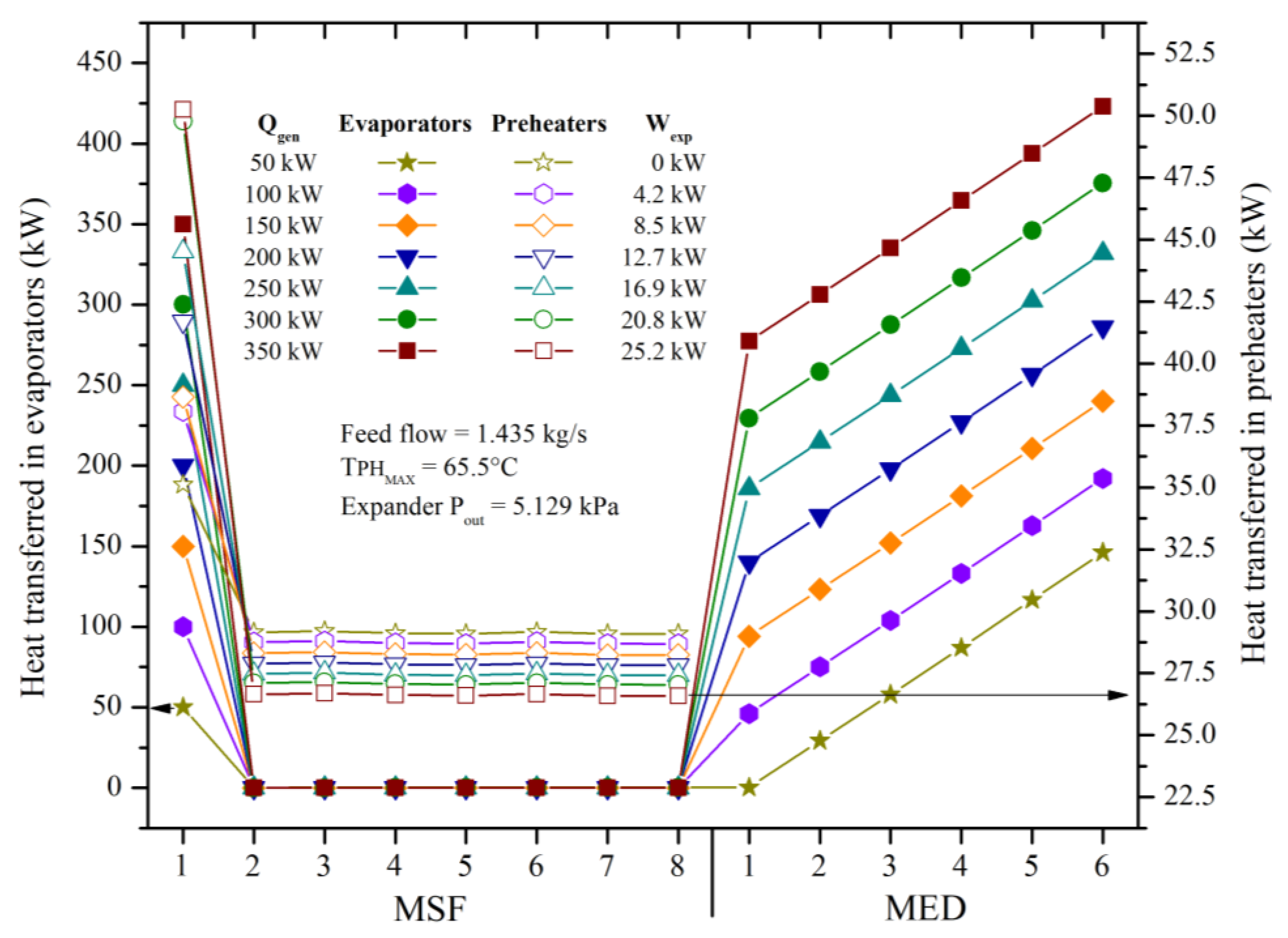
Figure 6.
- Boiling/flash steam generated in the stages/effects within the MSF/MED at high vacuum thermal desalination system.
Figure 6.
- Boiling/flash steam generated in the stages/effects within the MSF/MED at high vacuum thermal desalination system.
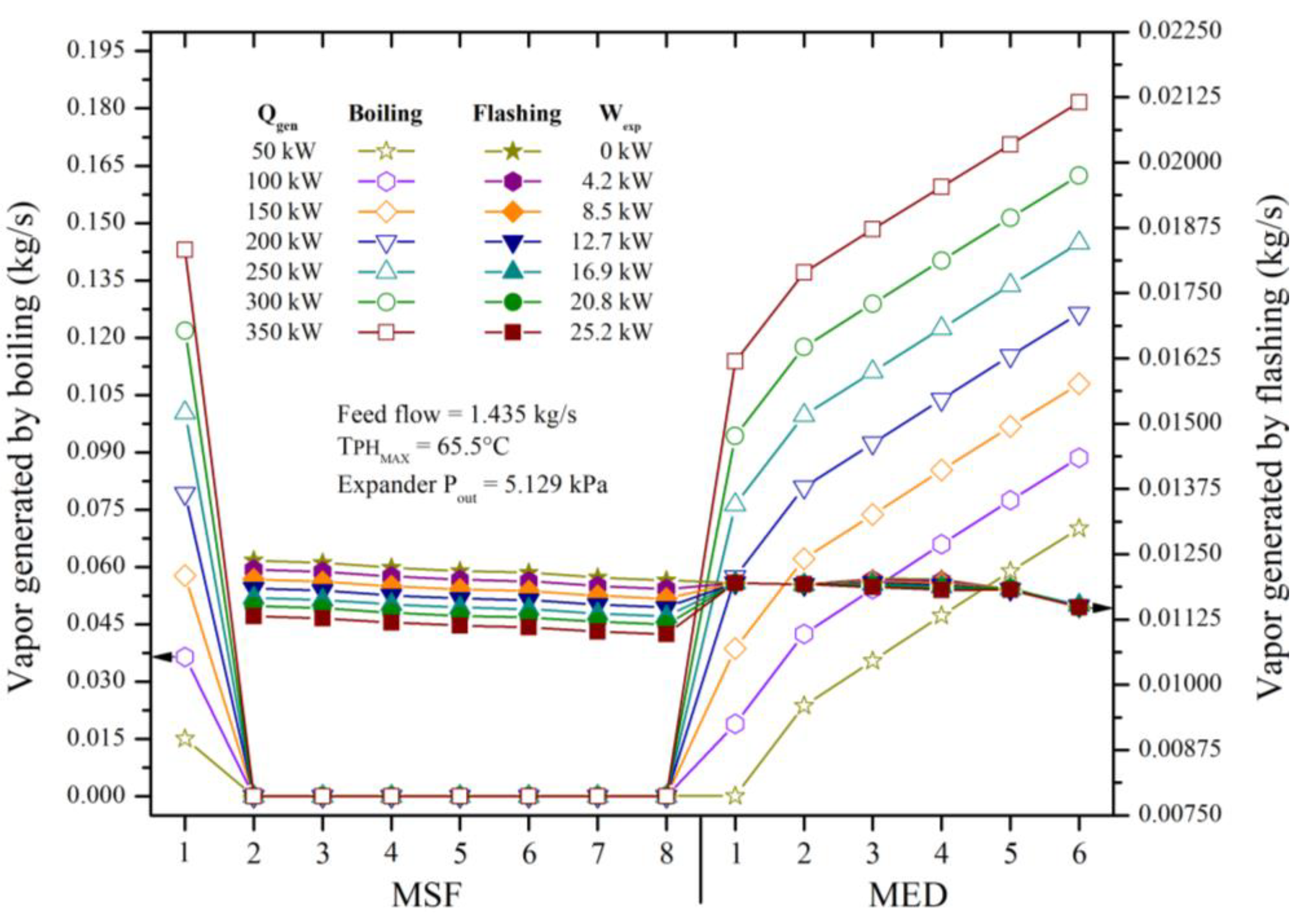
Figure 7.
- Effect of activation heat variation on internal variables of the thermal desalination subsystem.
Figure 7.
- Effect of activation heat variation on internal variables of the thermal desalination subsystem.
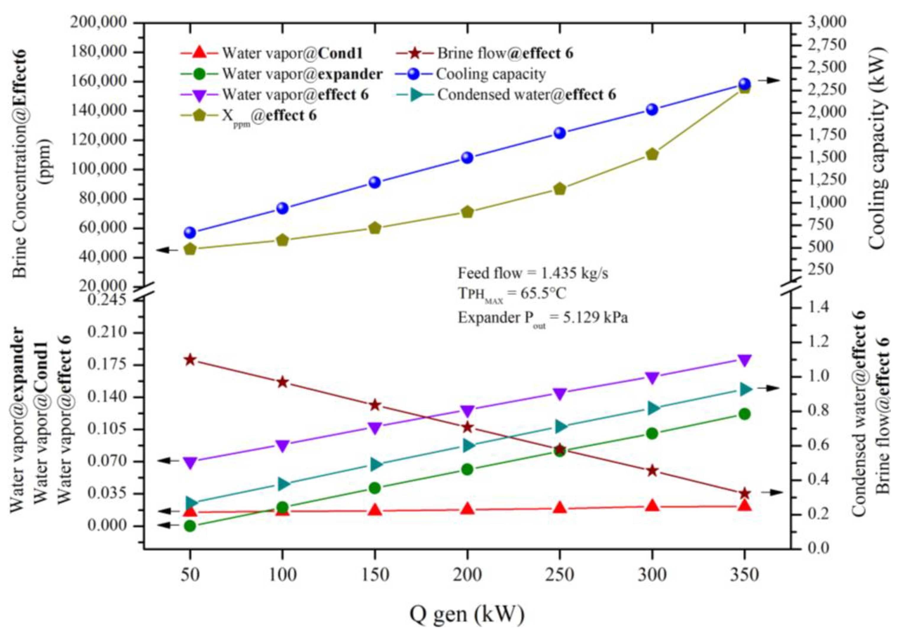
Figure 8.
- Effect of activation heat variation on brine concentration, heat exchanger, brine flow and secondary flow (SfEJ1), in cogeneration mode.
Figure 8.
- Effect of activation heat variation on brine concentration, heat exchanger, brine flow and secondary flow (SfEJ1), in cogeneration mode.
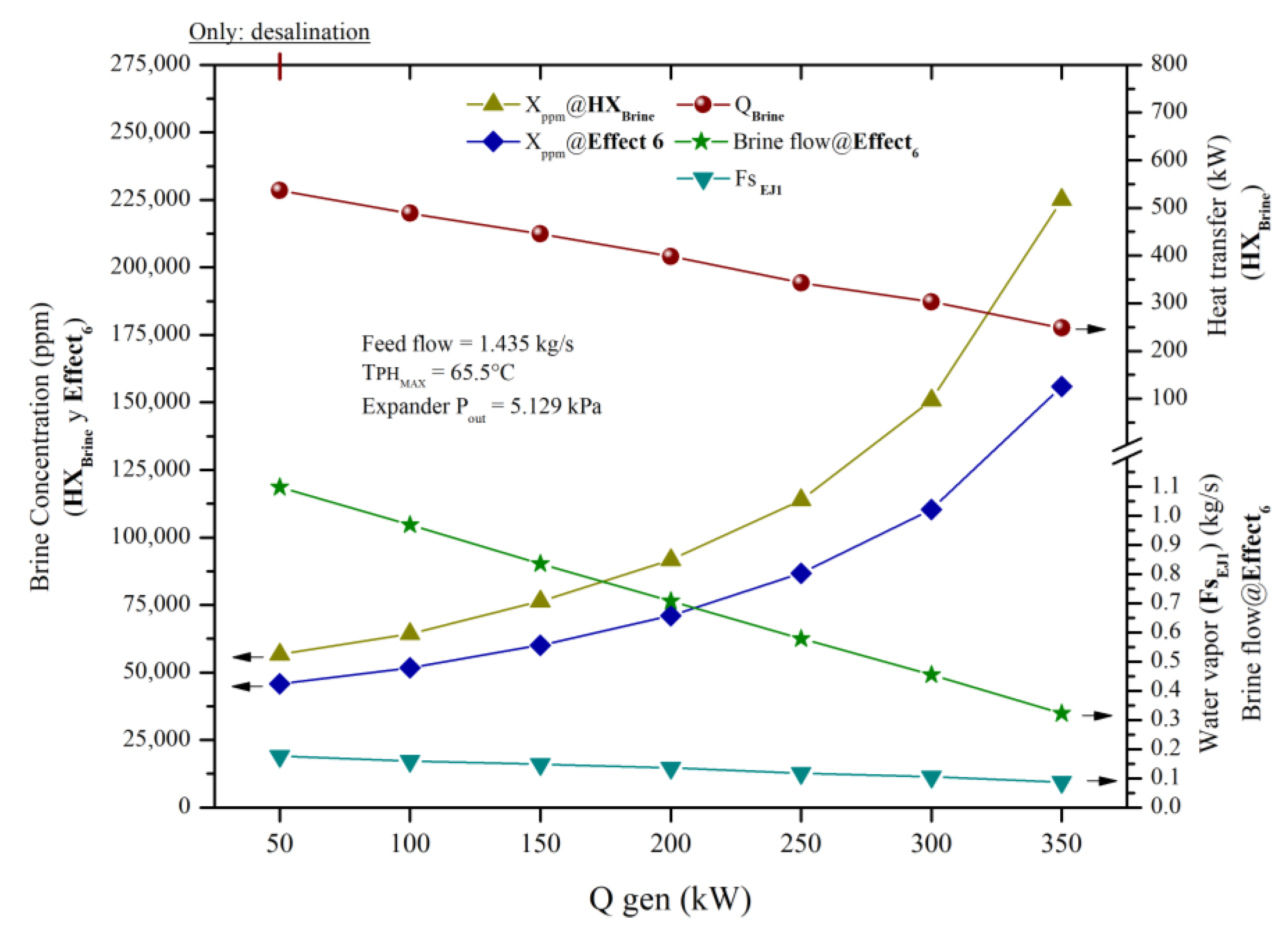
Figure 9.
- Influence on the variation of the activation heat in the motive flows, heat exchanger, secondary flows and electrical demand of the pumping system, in cogeneration mode.
Figure 9.
- Influence on the variation of the activation heat in the motive flows, heat exchanger, secondary flows and electrical demand of the pumping system, in cogeneration mode.
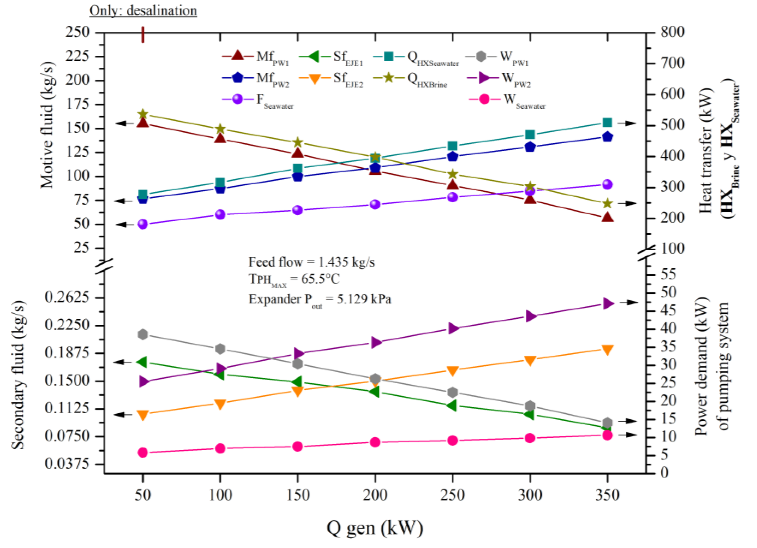
Figure 10.
- Effect of activation heat variation on electrical power, electrical demand, SECs and electrical coverage in cogeneration mode.
Figure 10.
- Effect of activation heat variation on electrical power, electrical demand, SECs and electrical coverage in cogeneration mode.
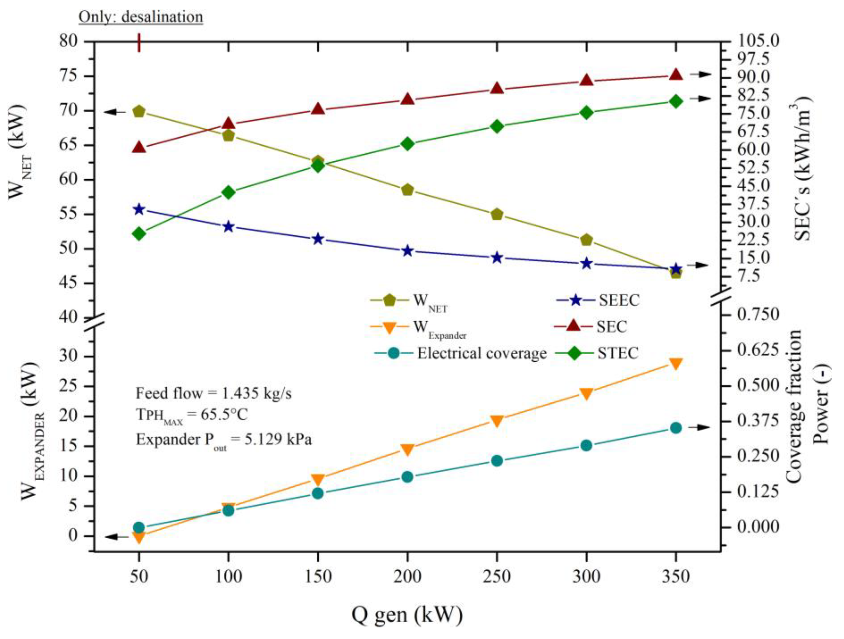
Figure 11.
- Effect of activation heat variation on desalination indicators: PR, PRglobal and recovery rate, in cogeneration mode. Principio del formulario.
Figure 11.
- Effect of activation heat variation on desalination indicators: PR, PRglobal and recovery rate, in cogeneration mode. Principio del formulario.
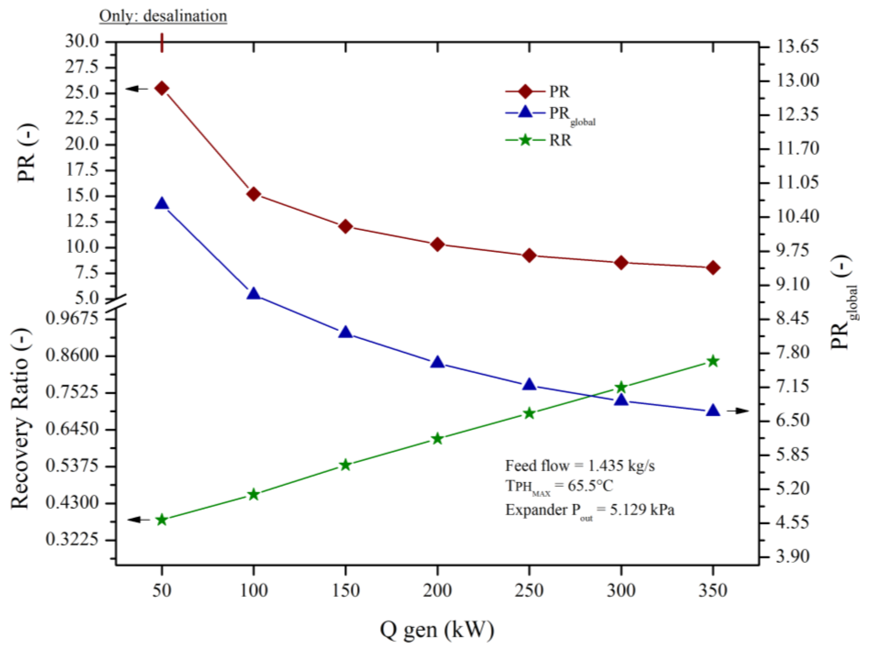
Figure 12.
- Effect of activation heat variation on brine concentration, heat exchanger, brine flow and secondary flow (SfEJ1), in trigeneration.
Figure 12.
- Effect of activation heat variation on brine concentration, heat exchanger, brine flow and secondary flow (SfEJ1), in trigeneration.
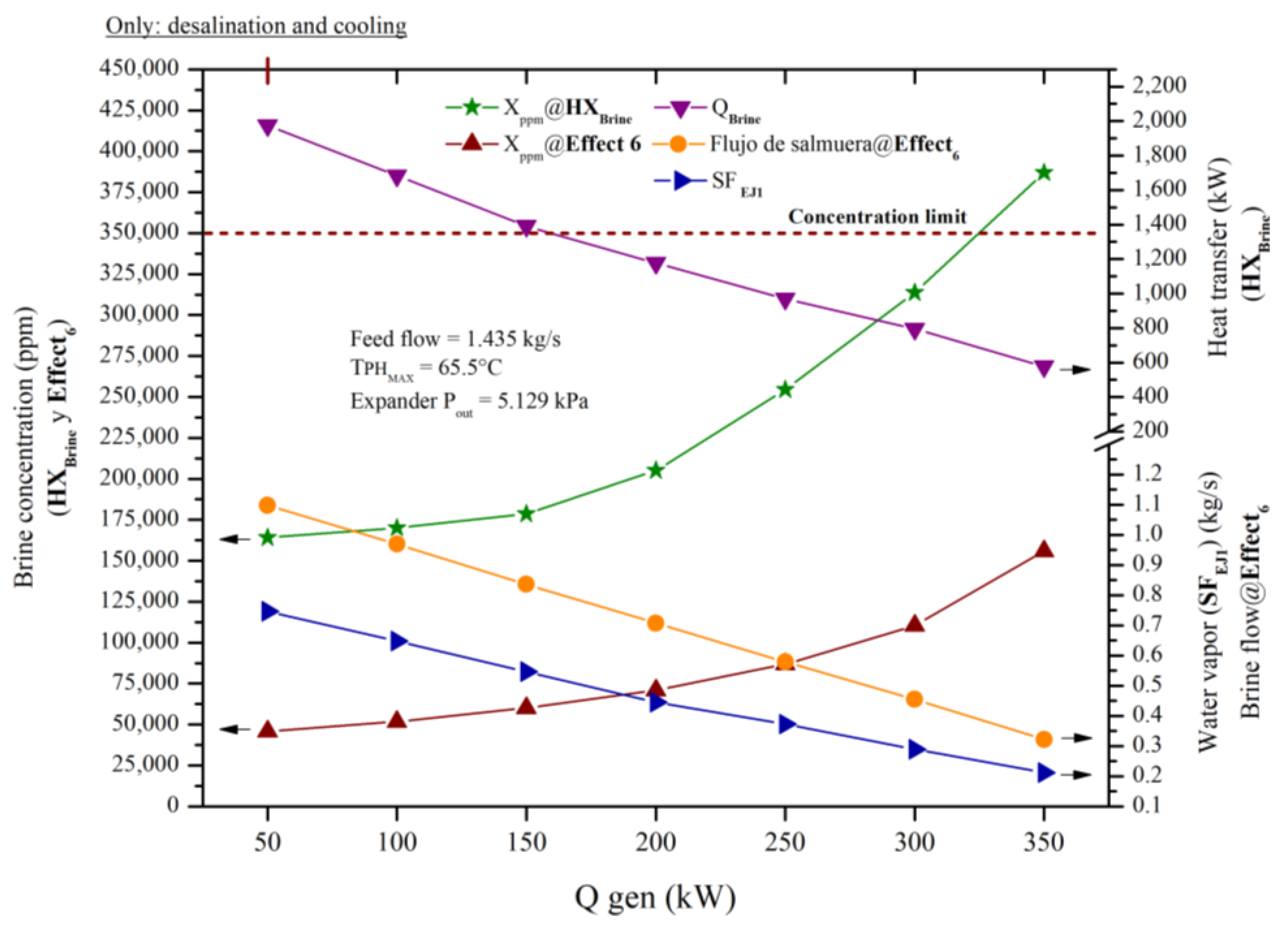
Figure 13.
- Influence on the variation of the activation heat in the motor flows, heat exchanger, secondary flows and electrical demand of the pumping system, in trigeneration.
Figure 13.
- Influence on the variation of the activation heat in the motor flows, heat exchanger, secondary flows and electrical demand of the pumping system, in trigeneration.
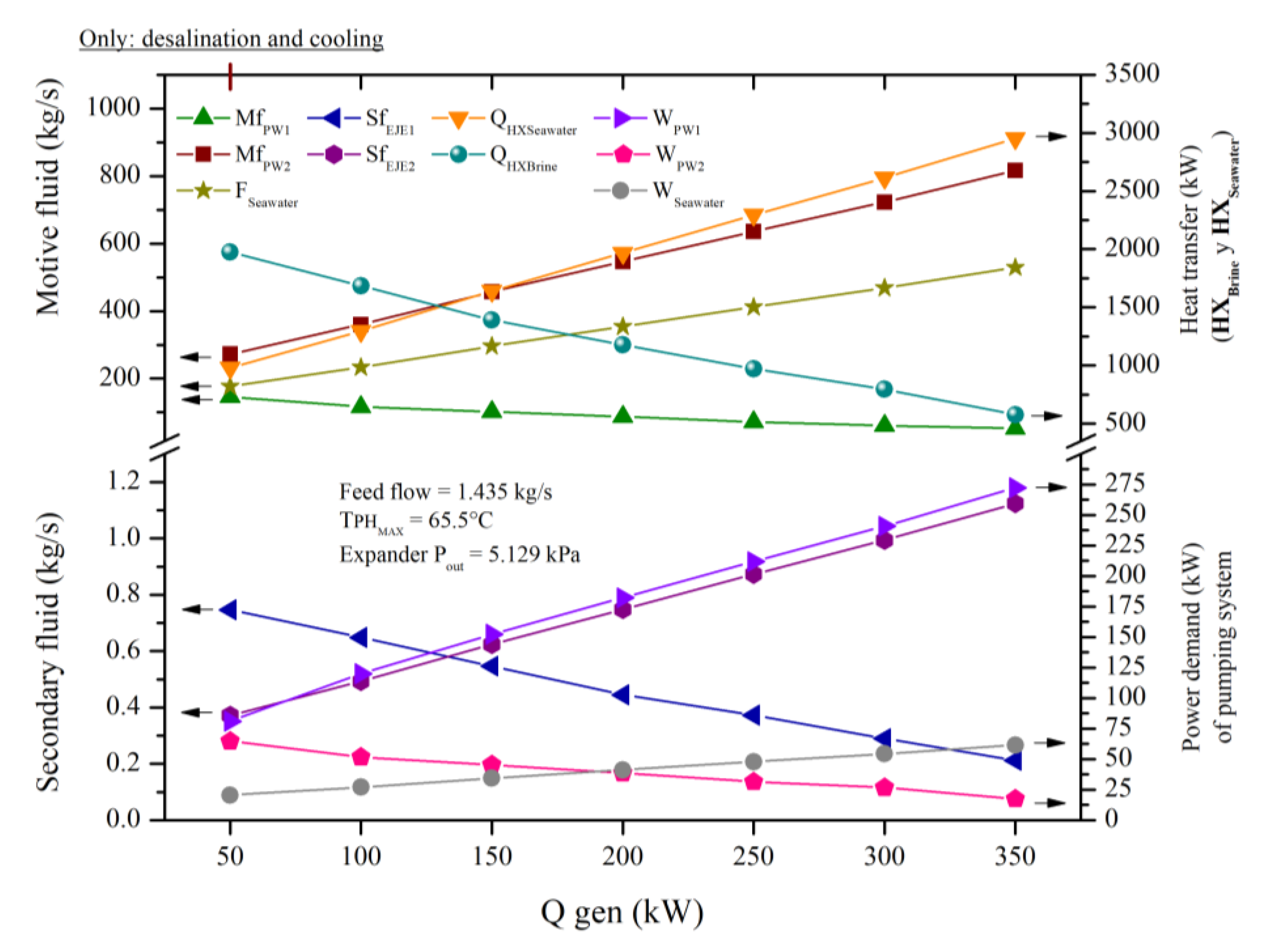
Figure 14.
- Influence of activation heat variation on electrical power, electrical demand, SEC's and electrical coverage in trigeneration.
Figure 14.
- Influence of activation heat variation on electrical power, electrical demand, SEC's and electrical coverage in trigeneration.
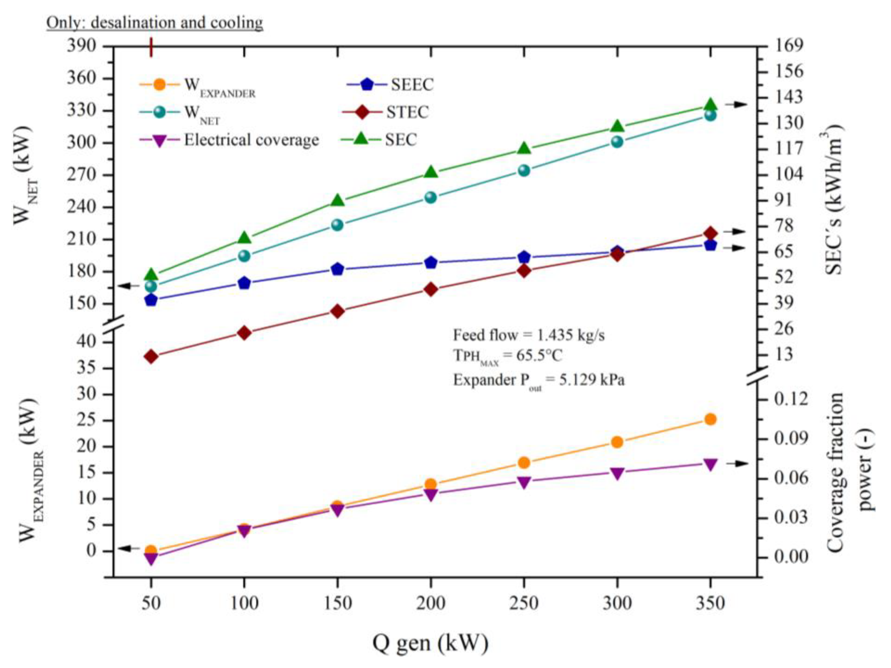
Figure 15.
- Effect on the variation of activation heat on the performance indicators PR, PRglobal, RR, COP and COPglobal, cooling capacity, in trigeneration.
Figure 15.
- Effect on the variation of activation heat on the performance indicators PR, PRglobal, RR, COP and COPglobal, cooling capacity, in trigeneration.
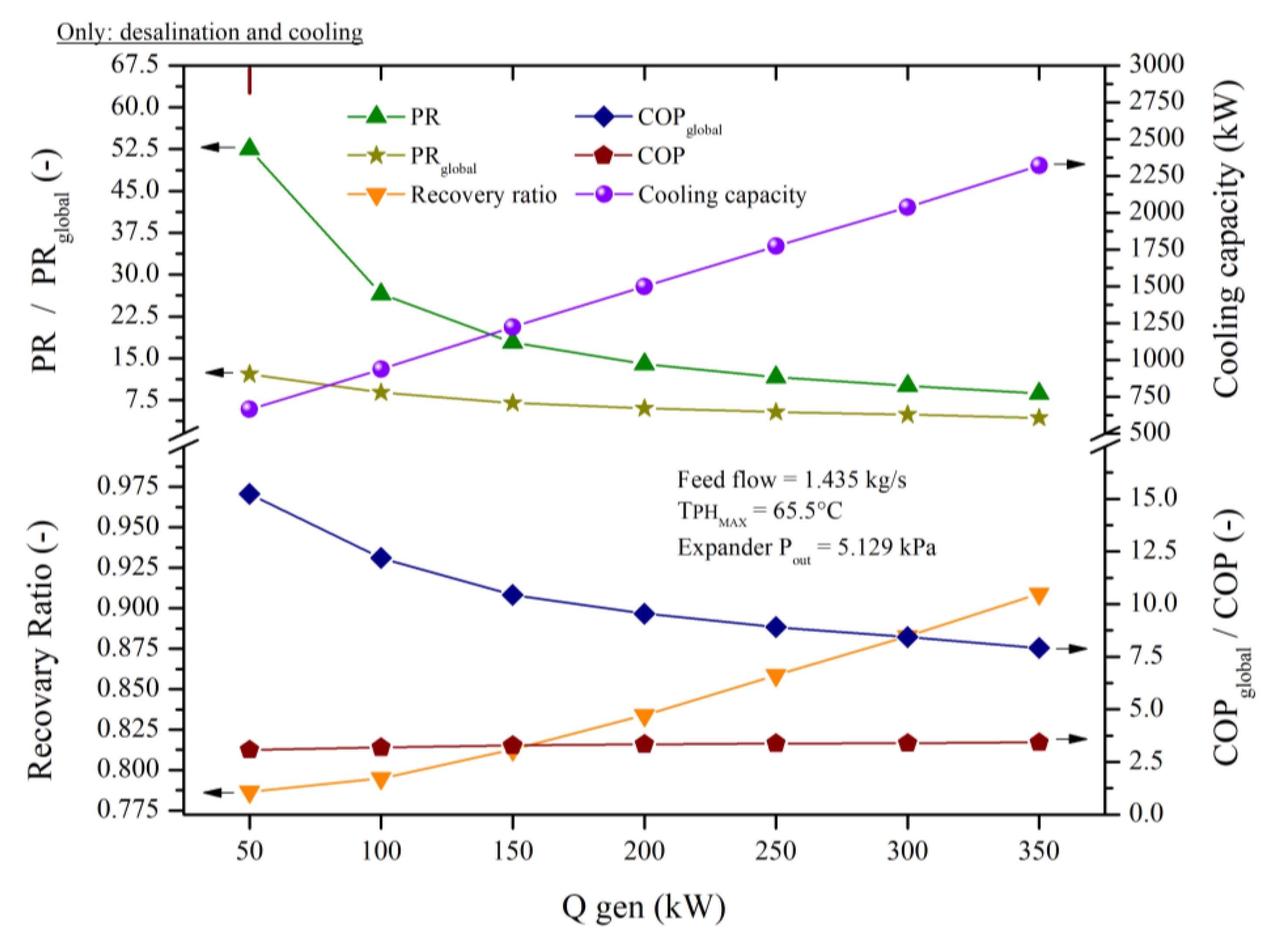
Figure 18.
- Influence on activation heat variation in product water, brine flow, steam generated in cogeneration and trigeneration.
Figure 18.
- Influence on activation heat variation in product water, brine flow, steam generated in cogeneration and trigeneration.
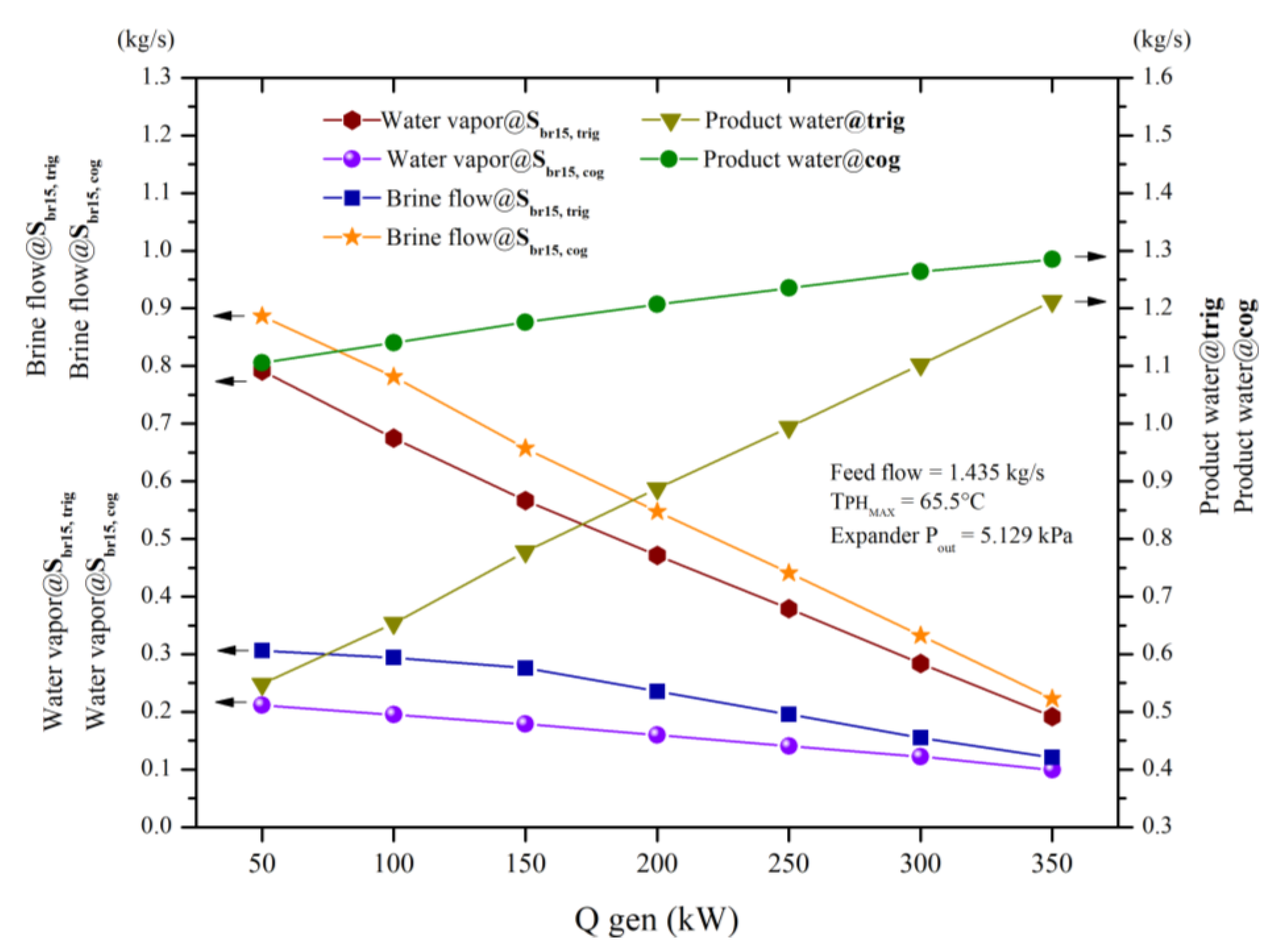
Table 1.
- Components, blocks in aspen plus and general equation of the proposed system.
| Component | Block in Aspen Plus | Symbology | General equation |
| • Generator (Gen) • Evaporator (EVA) • Exchanger 1 (HXbr) • Exchanger 2 (HXsw) |
HEAT X |  |
• • • • |
| • Pump 1 (Ppw1) • Pump 2 (Ppw2) • Pump 3 (Psw1) • Pump 4 (Psw2) |
PUMP |  |
• • • • |
| • Stage n | FLASH2 |  |
• |
| • Effect n | FLASH2 |  |
• |
| • Condenser 1 (PH1) • Condenser 2 (PH2) • • • Condenser 8 (PH8) |
HEATER |  |
• • • • • |
| • Spliter 1 (ST1) • Spliter 2 (ST2) |
FSPLIT |  |
• |
| • Mixer n | MIXER |  |
• |
| • Expansion Valve n | VALVE |  |
•
• |
| • Expander | COMPR |  |
• |
Table 2.
- Processes of the proposed system in the Aspen Plus simulation environment.
| Process | Blocks in Aspen Plus |
| STAGE 1 AND ACTIVATION SOURCE | 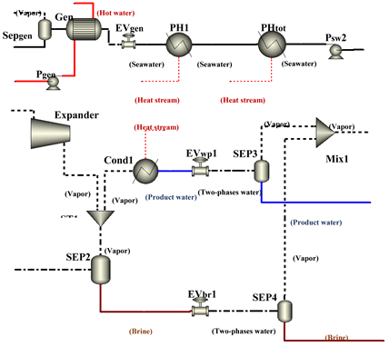 |
| STAGE 2-8 | 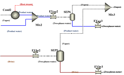 |
| EFFECT 1-5 | 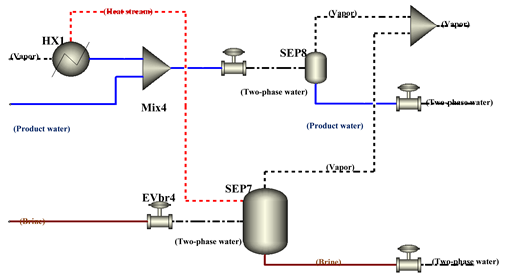 |
| EFFECT 6 | 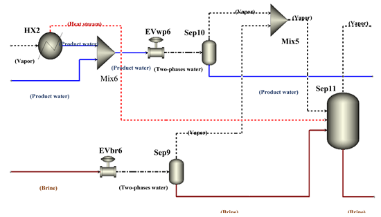 |
| SUBSYSTEM C-ECB | 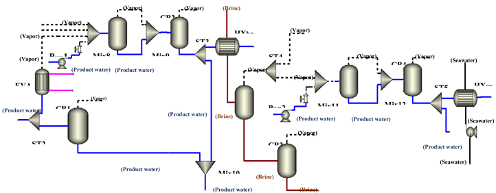 |
Table 3.
- Operating parameters of the MSF/MED thermal desalination subsystem at high vacuum.
| Parameters | Units | |
| No. of Flash stages | - | 8 |
| No. of MED effects | - | 6 |
| No. of preheaters | - | 8 |
| Top brine temperature (TBT) | °C | 68 |
| Bottom brine temperature (BBT) | °C | 4 |
| ΔT stages - effects | °C | 4.92 |
| Feed seawater temperature | °C | 25 |
| Salt concentration of feed seawater | ppm | 35,000 |
Table 3.
- Comparison of operational results of the experimental study reported by (Sağ et al., 2017) and this work.
Table 3.
- Comparison of operational results of the experimental study reported by (Sağ et al., 2017) and this work.
| Parameters | Units | Sağ et al. (2017) | This work | Error (%) |
| Condenser outlet temperature | °C | 57.64 | 59.02 | 2.394 |
| Evaporator outlet temperature | °C | 11.63 | 11.03 | 5.159 |
| Ejector outlet temperature | °C | 13.12 | 12.88 | 1.829 |
| Ejector outlet pressure | kPa | 456.00 | 456.00 | 0.000 |
| Entrainment ratio | - | 0.65 | 0.647 | 0.767 |
| COP | - | 2.12 | 2.115 | 0.236 |
| Compressor duty | kW | 2.11 | 2.10 | 0.332 |
| Cooling capacity | kW | 4.47 | 4.45 | 0.470 |
| Average duty | 1.398 |
Table 4.
- Comparison of exergy destruction between experimental results from (Sağ et al., 2017) and simulation in Aspen Plus.
Table 4.
- Comparison of exergy destruction between experimental results from (Sağ et al., 2017) and simulation in Aspen Plus.
| Component | Units | Sağ et al., 2017 | This work | Error (%) |
| Condenser | W | 71.88 | 78.64 | 9.4 |
| Compressor | W | 974.3 | 917.5 | 5.82 |
| Evaporator | W | 87.03 | 84.78 | 2.58 |
| Expansion Valve | W | 0.46 | 0.5 | 8.76 |
| Ejector | W | 188.2 | 188.71 | 0.27 |
| Separator | W | 35.76 | 35.61 | 0.42 |
| Exergy destroyed total: | W | 1357.63 | 1305.74 | 3.82 |
| Average error: | 4.44 |
Table 5.
- Main considerations and value ranges of the system parameters proposed by (López-Zavala et al., 2023) and the simulation in Aspen Plus.
Table 5.
- Main considerations and value ranges of the system parameters proposed by (López-Zavala et al., 2023) and the simulation in Aspen Plus.
| Parameters | Units | López-Zavala et al., 2023 | This work |
| No. Effects | - | 14 | 14 |
| TBT | °C | 70 | 70 |
| BBT | °C | 37 | 37 |
| ΔP effects | kPa | 3.13 | 3.13 |
| ΔT effects | °C | 2.5 | 2.5 |
| Operating temperatura range | °C | 70 - 35 | 70 - 35 |
| Salt concentration of feed Seawater | ppm | 35,000 | 35,000 |
| Seawater feed water temperature | °C | 27 | 27 |
| Hot source Flow rate | kg/s | 1.611 | 1.611 |
| Hot source temperature | °C | 95 | 95 |
Table 6.
- Simulation validation between the theoretical results of López-Zavala et al., 2023 and the simulation in Aspen Plus.
Table 6.
- Simulation validation between the theoretical results of López-Zavala et al., 2023 and the simulation in Aspen Plus.
| Results | Units | López-Zavala et al. (2023) | This work | Error (%) |
| Seawater temperature at condenser outlet | °C | 32 | 31.96 | 0.125 |
| Seawater temperature at the PH@12 outlet | °C | 64 | 64.1 | 0.156 |
| Product water capacity | kg/s | 0.865 | 0.859 | 0.694 |
| PR | - | 11.6 | 11.53 | 0.603 |
| RR | - | 0.53 | 0.5274 | 0.491 |
| COP | - | 4.7 | 4.67 | 0.638 |
| COPglobal | - | 9.325 | 9.291 | 0.365 |
| Cooling capacity | kW | 2042.87 | 2028.59 | 0.699 |
| Heat exchanged (condenser) | kW | 152.82 | 151.76 | 0.694 |
| Entrainment ratio | - | 0.0025 | 0.00243 | 2.800 |
| Heat exchanged (heatsink) | kW | 2297.54 | 2310.49 | 0.564 |
| Average error: | 0.47 |
Disclaimer/Publisher’s Note: The statements, opinions and data contained in all publications are solely those of the individual author(s) and contributor(s) and not of MDPI and/or the editor(s). MDPI and/or the editor(s) disclaim responsibility for any injury to people or property resulting from any ideas, methods, instructions or products referred to in the content. |
© 2024 by the authors. Licensee MDPI, Basel, Switzerland. This article is an open access article distributed under the terms and conditions of the Creative Commons Attribution (CC BY) license (http://creativecommons.org/licenses/by/4.0/).
Copyright: This open access article is published under a Creative Commons CC BY 4.0 license, which permit the free download, distribution, and reuse, provided that the author and preprint are cited in any reuse.


