

Submitted:
23 October 2024
Posted:
24 October 2024
You are already at the latest version
Abstract
The present study deals with an accident analysis of the “Chaira”- Bulgaria high pressure Pumped Hydroelectric Energy Storage (PHES), especially the failures of the Francis large scale Hydraulic Unit No. 4 (HU4). The causes of overloading and cracking of the stay vanes and their functionality are investigated. Despite many studies on the behavior of the runner and its safe operation the complete destruction of the system because of the stay vanes failure has not been sufficiently studied and published in the scientific literature. The aim is to assess the reasons that have led to this unprecedented accident of the “Chaira” PHES of total destructions of the stay vanes. Based on the historical data and the operating modes, as well as of the identification of the critical elements an objective assessment of the risks of damage of the stay vanes and of entire unit is proposed. A virtual prototype is built for simulation of the system behavior in working and emergency conditions. The loads, stresses and deformations are precisely calculated. The critical elements of the highly loaded blocks are evaluated. Low cycle material fatigue is with a high degree of confidence the dominated reason for the stay vane complete destruction. The results of the research are used to propose measures for possible rehabilitation and/or replacement of the unit.
Keywords:
PHES “Chaira” accident
; Francis’ turbine reliability
; spiral case destruction
; low cycle fatigue prediction
; stay vanes cracks
; Virtual Prototyping
1. Introduction
The needs for electric energy storage continuously growing because the share of the renewable sources as the solar and wind generating facilities grows rapidly, producing energy that in many cases should be stored because not matched current energy consumption. The most widespread and cost-effective storage technology is the Pumped Hydroelectric Energy Storage (PHES). The PHESs comprises about 96% of global energy storage capacity and 98% of global energy storage volume [1].
In [2] an assessment of the renewable electricity generation by PHESs in European Union member states was presented and the conclusion was that they provide the balance of the electricity storage market. The use of the reversible units in PHESs allows part of the excess energy in the system to be accumulated and returned it during the highest electricity consumption periods.
Other very important characteristics of hydro units are their great maneuverability and a very wide range of regulation, with high energy conversion efficiency. An example of good practice in the producing and use of electric energy is the Valhalla project in Chile, where in parallel with the construction of a photovoltaic plant with a capacity of 600 MW a PHES with a capacity of 300 MW is also being built [3].
Francis turbines are mainly applied in PHESs because their high effectiveness (more than 94%). They are used either as turbines or as pumps and could operate for short period of time withstanding many damaging transient conditions, such as pressure fluctuation, starting and stopping modes. During operation under adverse conditions, large pressure fluctuations are expected causing high static and dynamic stresses in the spiral casing, which can lead to fatigue failures. This type of damages has been reported more frequently in the recent years, as shown in numerous scientific articles and case studies [4,5,6,7,8,9].
Improving the reliability and operational capabilities of the power system can be achieved with the construction of new hydroelectric power plants and PHES and modernization of the existing ones. Trivedi and Cervantes investigated the methods for simulation and design process of PHES. They revealed the main reasons for severe incidents in the conventional hydropower plants and made recommendations how to avoid them [10].
Yasuda and Watanabe [11] studied and analyzed severe incidents of conventional hydropower plants in many countries in the period of 1990 – 2010. Incidents were reported for power plants in Canada, Romania and Serbia. In Russia the head cover of a 640MW Francis turbine broke away and the powerhouse was totally destroyed [12]. Many cracks were found at the trailing edges of the turbine blade for three Francis turbines of 200MW in Iran. The cause was vibration excited by Von Karman Vortex Street. The same severe vibrations where the reasons for the cracks found in two runners of a Francis turbine of 330MW in China. In Australia the spiral casing of Francis turbine of 150 MW failed by the excessive pressure rise due to the instant shut-down of all guide vanes [13].
Leading investigations have been conducted by Chinese scientists that more than two decades studied the reliability of different methods for embedment of the spiral casing. Very important role for the safety and accident-free work of Francis large PHES is the embedment of the spiral casing over the fundament. In [14] the structural deformations after the accident of the concrete in the Xiluodu hydro power plant located on the Jinsha River, Southwest China, were investigated. In [15] the effect of concrete cracks on dynamic characteristics of the Francis turbine and of the spiral casing was investigated. The Three-Gorge Dam on the Yangtze River near Sandouping, China was taken as an example to evaluate hydraulic forces including water pressure pulsation, the effect of the cracks on natural frequencies and the vibration responses of the powerhouse under hydraulic and earthquake forces. Yu et al [16] applied the finite element theory to calculate a spiral casing embedded with a cushion layer in order to study the influence of the reinforcement. They analyzed the concrete frame simplification, basement simplification and contact friction between spiral casing and the concrete. In [17] a constant internal pressure spiral case with non-uniform gap of hydropower stations, using ABAQUS FEM computation was simulated. Todorov et al. [18] analyzed the low frequency fatigue of the stay vanes. In [19] the spiral casing embedment and the influence of the gap between the chamber and the reinforced concrete was discussed.
In the papers [14,15,16,17] the topics related to the reliability of Francis turbines are discussed. Due to their wide operating pressure range (from a few meters to 700 m [20]), Francis turbines are the most used turbines for PHES. The analysis presented by the world-famous company GE Vernova, Cambridge, Massachusetts [21] shows that for about 60% of the global hydropower capacity in the world, Francis turbines are the most widely used type of hydro turbine.
There are many studies that have been focused on the main excitation types of dynamic loads in Francis turbines. Some of them are induced by the rotor-stator interaction (RSI) and are produced by Von-Karman vortices and stochastic excitations at very low loads [22,23,24]. RSI is the main excitation type for highly loaded rotating vanes. Von-Karman vortex shedding can be particularly dangerous if the frequency of the vortices coincides with an Eigen frequency of the impeller, creating resonance.
The cavitating vortex field and its effects on the turbine wheel have also been investigated in many studies. This phenomenon occurs when the machine is operating under partial load [25,26] and under overload conditions [27]. In [27] the consequences of an increased number of transient cycles, such as load variation, start-stop and total load rejection, on the turbines and the fatigue loading were discussed.
In addition to these excitations stochastic excitations must also be considered. They are particularly important at very low loads or during transient events. In [28] a one-dimensional hydro acoustic model was set up to perform the numerical simulation of the rotor-stator interaction of a Francis pump-turbine scaled model. Lyutov et al. [29] used stress pulsations amplitude to estimate the number of cycles until the moment of fatigue failure. The number of loading cycles and oscillation frequency are also used to calculate runner service time.
Fatigue analysis of the Francis turbine and casing is the major subject of the investigations of the present article. In Figure 1 the principal scheme of the Francis turbine is presented. With arrows the main parts of the turbine are denoted. Special attentions of the scientific literature survey are paid on the investigations regarding this subject and especially on the fatigue caused by the low frequencies. Several papers analyzed the hydraulic turbines and damages of Francis turbines caused by fatigue of the material [32,33]. Xin et al. [32] reviewed loading features and some key issues, e.g., different loads of operation, start-up, emergency shut-down, load rejections, and runaway, on the fatigue damage, and provides the latest information about different prediction approaches. They also analyzed other types of failures caused by cavitation, erosion and ingested bodies.
Under variable loading conditions, the use of the correct factor of safety in structural strength calculations is of particular importance. In [34] it is recommended for the fatigue safety factors to be more than 1.5 and guidelines are proposed for determination of fatigue cycles and crack propagation calculations. Flores et al. [35] have calculated the static and dynamic stresses in Francis turbines for assessment of the residual life. As a result, they have evaluated the life of the hydraulic unit and the formation of fatigue cracks. Birtarescu et al. [36} determined the loads and allowable stresses in the spiral chamber of the Francis turbine of the PHES unit. They considered additional loads and, accordingly, stresses on the spiral casing of a hydraulic turbine and on the stay vanes
In this article the reliability problems related to the stresses and deflections in the spiral chamber and stay vanes in case of Francis type systems are analyzed. Main attention is paid to the functionality and reliability of the stay vanes, which in the case of HU4 of PHES “Chaira” are the crucial elements and the main reason for the unit destruction. An assessment of the reliability is proposed, which in the case the fatigue phenomenon leads to a total failure of the system. These processes are not sufficiently studied and are the reason for the unprecedented accident of PHES “Chaira” and especially of HU4.
The reasons for the formation of cracks and the destruction of the stay vanes are studied in detail. The aim is to determine the critical elements based on the historical data on the exploitation and operation modes of HU4, as well as to carry out an objective assessment of the risks of failures and/or accidents. A virtual prototype for simulating of the behavior in working and emergency conditions, and precisely computation of the loads, stresses and deformations is developed. The critical elements and the causes of the cracks and destruction of the stay vanes are analyzed and evaluated. The results of the research prove that the cause of the destruction is low-frequency fatigue of the material of the stay vanes, as well as the influence of some technological processes on the load capacity and qualities of the steel used.
The present paper is a continuation of the authors' previous research [19] on the spiral casing embedment and the influence of the gap between the chamber and the reinforced concrete.
2. Materials and Methods
2.1. Fatigue Models for Destruction Analysis
Theories of elastoplasticity are generally based on the decomposition of the total strains into elastic and plastic components and to define the elastic and plastic deformation zones, see the Figure 2. The scheme shown includes: Monotonic Fracture (MF), Extremely Low-Cycle Fatigue (ELCF), Low-Cycle Fatigue (LCF), and High-Cycle Fatigue (HCF). The number of cycles N is plotted on the abscissa in a logarithmic scale, and the stress “σ” is plotted on the ordinate, also in a logarithmic scale.
Normally the distinction is made between HCF and LCF, ELCF and LCF modes. The HCF regime is determined by the level of working stresses and is associated with relatively low stress levels which are mainly in the elastic region of deformation. For this mode the fatigue life is greater than >105 cycles.
In contrast to the HCF, the LCF mode is determined by large strain amplitudes and is associated with high stress values that cause both elastic and irreversible micro-plastic deformations at each cycle. In this case the fatigue life is less than <104 cycles [37].
The ELCF mode is between the MF and LCF modes. It is defined by the yield strength and cyclic stress. Initial initiation of micro fracture under yield strength conditions is followed by plasticity exhaustion during cyclic loading until crack propagation occurs. Life in ELCF type fatigue mechanism is very short (<< 100 cycles).
Fatigue stresses that occur, for example, in a hydroelectric plant, can be divided into two parts, low-cycle and high-cycle [38]. LCF is in the range of up to about 100,000 cycles, while HCF refers to a higher number of cycles, typically over 10,000,000 cycles.
LCF is associated with micro plastic deformation in each cycle and subsequent build-up with hardening, while no such effects are reached in HCF.
A typical stress history for Francis turbine components or any type of machine that is subjected to various dynamic loads is shown in Figure 3, where Δσa, and σa are the stress amplitudes, and σm is the mean stress (see detailed explanations in [38]).
A start-stop cycle can be explained by several the LCF cycles shown in Figure 2. Stresses and strains (relative) change from a low value to a maximum and vice versa. In the LCF type of fatigue [38] two types of crack initiation are observed. Type A striations are visible as light and dark stripes. Type B (brittle) striations consist of river-like patterns with limited ductility and are as a result of micro plasticity. Fatigue fracture characteristics from fractographic images are good indicators to identify the fracture type.
The large number of studies on reliability, load modeling and the ability to evaluate fatigue failures in hydro-turbines are directed to the fatigue phenomena and failures mainly in the turbine runners. The stay vanes are important elements for the turbine functionality. The stay vanes reliability assessment is not sufficiently studied. They are of crucial importance since their fatigue destruction could lead to a total collapse of the system.
2.2. Subject of the Investigations
The object of research is the identification of the reasons for the destruction of the stay vanes of a single-stage reversible hydropower unit HU4) in the pumped-storage hydroelectric power plant PHES “Chaira”, Bulgaria. During the accident the average pressure has been 710 meters water height.
The first hydro unit HU1 of the PHES “Chaira” began operation in 1992 and at that time it was the one with the largest head in the world. A total of four hydro units are connected to the network consecutively. In the last few years, the rehabilitation of HU4 with over 12,000 hours of operation has been carried out. During commissioning tests of HU4 in a shedding test at 75% load generator mode and generating power of 176 MW, on March 22, 2022, an accident occurred. Increased noise and vibrations were detected, as well as ingress of water in the turbine bearing. For this reason, the block was stopped from the acceptance procedure. During a subsequent inspection a complete transversal failure of the integrity of 8 out of 10 stay vanes was detected and complete inoperability of HU4 was found.
In Figure 4 the destruction of the stay vane No. 1 of HU4 is presented. The cracks 1 and 2 are along the welding part of the stay vane. The inscriptions of the figure were made by the control officers before the photo was taken. The presence of such cracks indicates that the yield stresses were exceeded which led to local failure without visible plastic deformation in these areas. The analysis indicates that such destruction can be caused by static, dynamic or cyclic loads [18]. Specimens (test bodies) were taken from the defective elements (stay vanes) and research was conducted on the material characteristics after more than 20 years of operation. With particular relevance and importance, this accident poses the question of the causes that led to these avalanche-like cracks and the reliability of the remaining HUs.
The research is aimed at an analysis of the possible working and emergency loads and impacts, which led to the occurrence and propagation of cracks in the stay vanes of HU4. The study also includes a specific section in the frontal areas of the Stay Vanes (on the side of the runner) with evidence of previous repair of eroded sections as a result of operational cavitation. The repair was carried out before the general rehabilitation, carried out by conventional and proper way provided welding processes, during periodical minor repairs of the unit.
2.3. Methods of the Investigations
ANSYS nCode DesignLife [39] and ANSYS Mechanical were used for creation of the virtual prototype of HU4. This study and for reliable evaluation of the fatigue life. For the purposes of the simulation the working and emergency loads are estimated using the records of the operation history files and these for emergency events. Welding part of the stay vanes and base and upper rings, as well as the welding of the front surfaces of the stay vanes filling the cavities are investigated using simulation procedures.
The main hypothesis of the study is based on the established as shape, size and nature cracks. The aim is to study through simulations with the virtual prototype the behavior of the structure material and the loads that cause the cumulative fatigue. This includes identification of the critical components of the loads and determining the possibility of failure free operation through simulations of the behavior under different loads.
To determine the pressures on all working surfaces of the spiral chamber and the runner a fluid functional model of the unit was built using reference pressures from historical measurements and data in different operating modes. The research methodology uses the data from the tests of the material characteristics of the defective elements carried out by an accredited international laboratory at the request of the authors.
The virtual prototyping includes simulation of the Computational Fluid Dynamics (CFD) of the system for the different operating modes, the operating loads and their consequences for determination of the stresses and the strains. This methodology provides a quantitative and objectively accurate assessment, within the statistical inaccuracy, for the causes of the accident as a result of the geometric, material, technological, operational and other specifics of the PHES „Chaira“ HUs, and also as a function of the history of the operation. Figure 5 shows a block diagram of the actions of the research methodology. Each action (A1 – A5) includes specific activities shown in the blocks of the figure below.
- A1 – analysis of the operational history from the records of the monitoring and control system of the PHES “Chaira” and especially of the damaged HU4.
- A2 – creation of a Virtual Prototype based on a Computational Fluid Dynamic (CFD) model and the Finite Elements Method (FEM) model for structural-plastic simulations of transient, operating and emergency modes in order to identify the most loaded elements of the system.
- A3 – analysis of the working dynamic pressures through integrated CFD simulations of the transient, working, emergency and compensatory modes of the HU4, as well as the load rejection in the generator and pump modes.
- A4 – as a result of elasto-plastic simulations with the virtual prototype using the operational history of HU4, the most stressed elements of the system are determined and analyzed, with a focus on the defective stay vanes. The critical values of the strains and stresses in the failure elements are calculated.
- A5 – the final analysis is performed making the conclusions of material and low-cycle fatigue. It is estimated the probability of occurrence and avalanche-like growth of cracks, as well as the possibility of complete transverse destruction of eight out of ten stay vanes and a complete loss of unit operability.
The research described in this paper was carried out by the Technical University – Sofia, Center for Excellence of "Mechatronics and Clean Technologies", Bulgaria.
2.4. Historical Records of the Loads and the Working Conditions for HU4
In this section the historical records for the HU4 of PHES “Chaira” on the cycles and operation time have been studied In Table 1 the numbers of cycles for the different operating modes are presented for the entire period of exploitation. Data on the cycles into emergency operating modes (compensatory modes) are also provided in Table 1. It is important to note that the manufacturer recommend up to 12 on/off or reversal (pump/turbine) mode cycles of a hydro unit in total per day.
The data from the existing monitoring and control system were used to determine the pressure values at the inlet of the spiral casing in the generator mode and the pump mode. They are characterized by small peak loads in the transient modes. This is evident from the load diagram shown in Figure 6 which shows the pressure inside the penstock and the turbine spiral casing as well as the opening of the wicket gate at 75% load. Analysis of the data highlights five main modes:
- S1 – nominal generator mode;
- S2 – generator mode at peak in transient mode, pressures exceed by approximately 12%;
- S3 – pump nominal mode;
- S4 – pumped mode at peak in transient mode, the pressures exceed approximately 7% the nominal pressures for the pump mode;
- S5 – load rejection in generator mode.
An analysis of the charts provided by the Supervisory Control and Data Acquisition (SCADA) system was performed, and no significant "hydraulic shock" was detected as a result of the rapid closing of the wicket gate apparatus. All the parameters changes of the charts are within the permissible limits for cases of power load failure.
From the history records of the HU4 in the period of 2001 – 2003 increased frequency of start/stop/reverse cycles were registered. For the whole period of HU4 operation about 40,000 hours of work and 11,856 total numbers of cycles in the various modes are registered. By comparing the historical data with the manufacturer's recommendations, it can be concluded that the prescriptions for the number of cycles and working hours per day, as well as for these values accumulated over time, have not been violated.
The analysis of the pressures during emergency situations in the electric network caused by the loss of the electrical load in generator mode or the loss of power in pump mode (no more than a few for the entire period of operation) showed significant transient processes associated with the change in the direction and magnitude of the load. Short-term large overshoot of established operating pressures in various power modes was observed. The largest pressure peaks were found when the load is rejected in generator mode. Then they exceed the nominal values by up to 15%.
2.5. Design of the Virtual Prototype of HU4
2.5.1. Geometrical Model of the Spiral Casing and the Concrete
The created virtual prototype is based on a 3D geometric model according to the features of the modeled structures of the spiral casing, the stay and guided vanes, the runner and the enclosing concrete structure.
The model was created based on the provided design documentation of the spiral casing and the concrete structure. The created geometric model is shown in Figure 7 (concrete and metal structure only).
The virtual prototype includes also data of the samples from the defective columns, welded cavities and the micro cracks of the welded area of the stay vanes. These data are obtained from a report provided by TECHNISCHE UNIVERSITÄT DARMSTADT – FI - 182/2024 "Investigations on damaged stay vanes of the PSHPP „Chaira“", H. Th. Beier, M. Vormwald, P. Yadegari.
In the same report, the presence of incompletely cleaned cracks was also found and a hypothesis was raised about residual uncleaned micro-cracks and subsequent initiation of cracks. The hypothesis was based on the conclusion that the failure of the stay vanes was due to inadequate mechanical properties of the material used for welding and that after cleaning, a small part of the cracks was not completely repaired and covered by welding. This was probably made before the rehabilitation carried out in a traditional manual way for similar cases of welding used by National Electric Company (NEK) EAD [https://www.nek.bg/index.php/en/]. The inclusion of these specific areas in the virtual prototype aims to analyze the possibility that the cracking process started and grew in this way. The micro-cracks, the cavities, from the front side of the defective stay vanes are shown in Figure 8.
In Figure 9 the geometry model of a stay vane edge, including the welded cavity zone is shown.
2.5.2. Finite Element Model of the Turbine, Spiral Casing and the Concrete
The three-dimensional finite element model was generated using hexahedral elements, Figure 9. It also includes the concrete structure components as well as the spiral casing and the stay vanes. Special attention was paid to the welded sections of the stay vanes and their zones, which were repaired of cavities.
2.6. Materials Used for the Concrete and the Metal Structure of the HUs of PHES “Chaira”
The material used for the spiral casing is identified as HT60 high strength structural steel. The steel for the stay vanes and stator rings is steel JIS G 3106 SM 50. The materials used for welding has properties according to the welded units. In Table 2 the specifications of the steels and the concrete are presented.
Additional data is needed on the fatigue properties of the materials, as the estimation of the fatigue and low-cycle fatigue requires the use of a dependence of the number of cycles on the deformation. The fatigue data of the materials (Figure 11, a) used in the construction of the virtual prototype was determined according to the information provided in the Materials Testing Institute University of Stuttgart, Report-No.: 904 2634 004 “Chaira” - Damage Case Unit 4, WP4: Strain-Controlled Fatigue Tests (LCF). The resulting fatigue curve is shown in Figure 11 (b). This curve is approximated by mathematical methods to the following function:
Thus, it becomes possible to determine the number of cycles N at different relative deformations of the structure. The plot of the approximating function is shown in Figure 10 b.
2.7. Boundary Conditions for the Fluid Model
Total of 5 load cases were investigated (Table 3). The applied boundary conditions are of the following types: Full pressure at the inlet of a volute chamber;
- Full pressure at the system outlet – 7 bar;
- Turbine RPM.
3. CFD Analysis for Detailed Determination of Loads
A series of analyzes of the Computational Fluid Dynamics (CFD analyses) were planned. The designed virtual prototype of the system and the creation of a computational structural model were used. The computational fluid model is shown in Figure 12.
3.1. Computational Fluid Model
In Figure 12 the geometry and mesh model for CFD simulations is presented.
3.1. Results in Generator Mode (S1)
Figure 13 shows the vector distribution of the fluid particle velocities, showing the general appearance of the studied fluid flow. The trajectories of particles passing through the turbine spiral casing (Figure 13 a) and outlet (Figure 13 b) are also shown, colored according to their velocity.
Additionally, in Figure 14 the distribution of turbulent kinetic energy in axial (Figure 14 a) and radial (Figure 14 b) turbine cross sections are shown. High turbulence can be seen at the outlet of the turbine as well as near the static guides.
The main result of this analysis is the determination of the pressure ratios in the different parts of the studied area. The distribution of the total pressure in the zone of the static parts in the axial cross section of turbine is shown in Figure 15.
3.2. Results at Pump Nominal Mode (S3)
In Figure 16 the vector distribution of the fluid velocity in the radial cross section of the spiral casing is shown. The determination of the pressure ratios in the spiral casing and along the outlet tube was made on the basis of the distribution of the total pressure in an axial cross section. The numerical values of the total pressure in the axial cross section of the spiral casing and the outlet tube are shown in Figure 17.
3.3. Results at the Load Rejection Mode (S5)
The numerical results for the total pressure for S5 mode, similarly to the S3 mode, the numerical values of the total pressure in the axial cross section of the spiral casing and the outlet tube are shown in Figure 18.
4. Results
Using state-of-the-art engineering solutions, it is possible to make an accurate assessment of the probability that material fatigue is the cause of the accident. For this purpose, a virtual model was built for engineering analysis and simulation of the spiral casing of the unit as well as its’ associated elements. The goal is an analysis of the strength-deformation behavior of the defective elements.
Five simulations of the structure were carried out under the loads and operating modes defined above – S1, S2, S3, S4 and an assessment of the construction parameters regarding stresses and strains, including in the non-linear area of the material behavior, was made. The second and sixth stay vanes are selected analyzed in detail
4.1. Structural Mechanical and Elasto-Plastic Simulations
The results of the engineering analyzes for the sixth stay vane at load rejection (mode S5) are presented. In the Figure 19 (a) and in the Figure 20 (a) the values of the equivalent stresses and the equivalent strains, respectively, are shown using colors. In the Figure 19 (b) and Figure 20 (b) these values are directly shown on a front edge of the sixth stay vane. It can be seen that for this load mode the highest values of the stresses and strains are on the front edges of the stay vanes and reach values between 380 and 500 MPa.
The results, taking into account the plasticity of the materials, indicate that the maximum stresses of the materials are not exceeded the material limits during the initial testing of the hydraulic units. However, zones of plastic strengthening were noticed, which lead to this drop of the stresses and, accordingly, to the appearance of micro-plastics and the opportunities of initiation of cracks in the hydraulic unit HU4. The transient processes starting, stopping and reversing of the hydroelectric plant can be the reason for reaching of high levels of the work loads. The resulting stresses at the limits of transition to micro-plastics can definitely be the cause of LCF.
These results indicate that the most probable cause of the crack is the low-cycle fatigue in the zones of maximum load of the stay vanes.
4.2. Analysis of the Possibility of Sudden Failure and Material Fatigue
The analysis of the values of the maximal deformations for the five modes of hydraulic units operations are presented in Table 4.
The computational results indicate unequivocally that low-cycle fatigue of the material is expected to occur. This will lead to failure under cyclic loading at about 10,000 - 14,000 number of cycles that include: on Pump/Generator; off Pump/Generator; emergency stops. The fatigue curves of the materials in Figure 11 compared to the computational results confirms this conclusion.
5. Discussion
- The results of the fluid simulations of the loads during operation in the Start/Stop/Reversal modes and during Emergency Stops of HU4 in Generator/Pump modes have been used to the structural-mechanical model of behavior of the virtual prototype.
- The results of the elasto-plastic simulations of the stresses and strains for the different modes show with high reliability that the maximum stresses in the specific zones of stay vanes exceeded the allowable limit stresses for steel JIS G 3106 SM 50 A and for the concrete B25 in terms of yield strength.
- The above arguments confirm the hypothesis of the occurrence of low-cycle fatigue as a result of the occurrence of local stresses (cyclic, with the frequency of start/stop/reversal) above the permissible linear values for the corresponding material steel JIS G 3106 SM 50 A. This leads to the accumulation of micro-plastic irreversible deformations and to the appearance of low-cycle fatigue cracks.
- In the moments of emergency modes the intensive spread of micro-plastic deformations occurs. This is accompanied by even higher stresses due to the weakening of the load-bearing capacity of the stay vanes specific areas. The cracks that have appeared after a certain limits lead to an avalanche-like cracking of most of the stay vanes.
To prove the conclusions from the simulation of the force-deflection behavior of HU4 under working and emergency loading, the following was carried out:
- taking physical samples of the damaged areas (cracks) from the front faces of the stay vanes;
- Study of the residual strength of the sample materials by experimental standard test in a certified laboratory.
6. Conclusions
Thorough analysis of the load history under normal operation and under the specifics of various emergency stops has been carried out on the base of Virtual Prototype and real data usage. The pre-commissioning test trials have been carried out. In the transient modes of operation in the structure and in particular in the stator columns, overloads and accumulation of micro-plastic deformations are observed.
It can be affirmed with a high degree of confidence that the cracks in eight of the ten stay vanes of HU4, obtained during the pre-commissioning test trials, are in the result of low cycle material fatigue. The reason is high working loads in certain stay vane’s zones leading to accumulated micro-plastic deformations caused by the cyclic load during starting, stopping and especially when load rejection events have occurred. This is followed by a rapid growth of the micro-cracks and an additional concentration of stresses until an avalanche-like destruction process is reached in these areas.
Erosion defects and micro-cracks were found on the front surfaces of the stay vanes on the side of the runner. These places were cleaned and welded to the nominal shape before the rehabilitation activities were carried out. However, the impact zones are much smaller than the regions of overload stay vanes and micro-plastic strains accumulation leading to low-cycle fatigue. It is possible that these interventions are related to the cracking process, but they are definitely not the main reason for the occurrence of fatigue failure. This is also proven by the fact that complete cracking of two stator columns is also observed at HU1 at PHES “Chaira”, which was not subjected to welding and restoration/resurfacing.
In order to prove the simulation results the authors requested the operating staff to take samples from the damaged areas (cracks) in the regions around the front surfaces of the stay vanes. Experimental tests were carried out in a certified laboratory to measure the residual strength and fatigue properties of the sample materials.
The results reported in the research laboratory (Report Damage Case Unit 4 – Root Cause Analysis N 29970000_525-001 29 November 2023, AF-Consult Switzerland AG c/o AFRY Swiss AG) categorically prove the raised in this article hypothesis about the root cause of the failure, i.e. the reason is the low-cycle fatigue of the material as a result of high load modes in certain areas leading to micro-plastic deformations with accumulation during cyclic loading.
Author Contributions
Conceptualization, G.T. and K.K.; methodology, G.T., K.K., and Y.S.; software, B.Z.; validation, I.K. and Y.S.; formal analysis, G.T.; investigation, K.K. and B.Z.; resources, Y.S.; data curation, B.Z. and Y.S.; writing—original draft preparation, K.K.; writing—review and editing, G.T. and K.K.; visualization, Y.S. and B.Z.; supervision, I.K.; project administration, G.T. and I.K.; funding acquisition, I.K.; editing, consultation and review E.Z. All authors have read and agreed to the published version of the manuscript.
Funding
This study is financed by the European Union—Next Generation EU, through the National Recovery and Resilience Plan of the Republic of Bulgaria, project № BG-RRP-2.004-0005 and by the project КП-06-Н67/8 Development of a fluid–structural methodology for the study and modernization of turbomachines, through the virtual prototyping—HydraTech“.
Data Availability Statement
The data presented in this study are available on request from the corresponding author. The data are not publicly available due to relation to public funding specifics.
Conflicts of Interest
The authors declare no conflicts of interest.
References
- Available online: https://www.energy.gov/eere/water/pumped-storage-hydropower (accessed on 24 July 2024).
- Punys, S.; Baublys, R.; Kasiulis, E.; Vaisvila, A.; Pelikan, B.; Steller, J. Assessment of renewable electricity generation by pumped storage power plants in EU Member State. Renewable and Sustainable Energy Reviews 2013, 26, 190–200. [Google Scholar] [CrossRef]
- Yang, J.; Robert, B.; Jackson, R.B. Opportunities and barriers to pumped-hydro energy storage in the United States. Renewable and Sustainable Energy Reviews 2011, 15, 839–844. [Google Scholar] [CrossRef]
- Egusquiza, E.; et al. Failure investigation of a large pump-turbine runner. Engineering Failure Analysis 2012, 19, 27–34. [Google Scholar] [CrossRef]
- Momčilović, D.; et al. Failure analysis of hydraulic turbine shaft. Engineering Failure Analysis 2012, 20, 54–66. [Google Scholar] [CrossRef]
- Dorji, U.; et al. Hydro turbine failure mechanisms: an overview. Engineering Failure Analysis 2014, 44, 113. [Google Scholar] [CrossRef]
- Zuo, Z.; et al. Pressure fluctuations in the vaneless space of High-head pump-turbines—a review. Renew Sustain Energy Review 2015, 41, 965–974. [Google Scholar] [CrossRef]
- Liu, X.; et al. A review on fatigue damage mechanism in hydro turbines. Renew Sustain Energy Review 2016, 54, 1–14. [Google Scholar] [CrossRef]
- Müller, A.; et al. Fluid–structure interaction mechanisms leading to dangerous power swings in Francis turbines at full load. Journal of Fluids Structures 2017, 69, 51–56. [Google Scholar] [CrossRef]
- Trivedi, C.; Cervantes, M.J. State of the Art in Numerical Simulation of High Head Francis Turbines, Renewable Energy Environ. Sustainability 2016, 1, 1–20. [Google Scholar]
- Yasuda, M.; Watanabe, S. How to Avoid Severe Incidents at Hydropower Plants. Int. J. Fluid Mach. Syst. 2017, 10, 296–306. [Google Scholar] [CrossRef]
- Available online: https://en.wikipedia.org/wiki/Sayano-Shushenskaya_power_station_accident (accessed on 4 July 2024).
- Price, J.W.H. The failure of the Dartmouth turbine casing. International Journal of Pressure Vessels and Piping 1998, 75, 559–566. [Google Scholar] [CrossRef]
- Gao, X.; Fu, D.; Wu, H. Embedment of Steel Spiral Cases Casings in Concrete: Lessons from a Structural Deformation Accident in China. Applied Science 2022, 12, 8395. [Google Scholar] [CrossRef]
- Tian, Z.; Zhang, Y.; Ma, Z.; et al. Effect of concrete cracks on dynamic characteristics of powerhouse for giant-scale hydrostation. Trans. Tianjin Univ. 2008, 14, 307–312. [Google Scholar] [CrossRef]
- Yu, Y.; Zhang, Q.L.; Wu, H.G. Reinforcement calculation for spiral casing embedded with cushion layer of hydropower station. Tianjin Daxue Xuebao (Ziran Kexue yu Gongcheng Jishu Ban). J. Tianjin Univ. Sci. Technol 2009, 42, 673–677. [Google Scholar]
- Xu, X.; Li, M.; Ma, Z.; Zhang, H.; He, P. Simulation and analysis of the constant internal pressure spiral casing with non-uniform gap. Shuili Fadian Xuebao. J. Hydroelectr. Eng 2009, 28, 75–80. [Google Scholar]
- Todorov, G., Kralov, I., Kamberov, K., Sofronov, Y., Zlatev, Bl. Failure mechanisms of stay vanes in a PHES Francis turbine unit. In Proceeding of the 13th International Scientific Conference “TechSys 2024” – Engineering, Technologies and Systems, Location of Conference, Plovdiv, Bulgaria, 18 May 2024.
- Todorov, G. Kralov, I., Kamberov, K., Zahariev, E., Sofronov, Y., Zlatev, B., An Assessment of the Embedment of Francis Turbines for Pumped Hydraulic Energy Storage. Water 2024, 16, 2252. [Google Scholar] [CrossRef]
- Presas, A.; Yongyao, L.; Zhengwei, W.; Bao, G. Fatigue life estimation of Francis turbines based on experimental strain measurements: Review of the actual data and future trends. Renewable and Sustainable Energy Reviews 2019, 102, 96–110. [Google Scholar] [CrossRef]
- Available online: https://renewables.gepower.com/hydro-power/large-hydropower-solutions/hydro-turbines/francis-turbine.html (accessed on 24 August 2024).
- Fisher, R.; Seidel, U.; Grosse, G.; Gfeller, W.; Klinger, R.A. Case Study in Resonant Hydroelastic Vibration: The Causes of Runner Cracks and the Solutions Implemented for the Xiaolangdi Hydroelectric Project. In Proceedings of the 21st IAHR Symposium, Lausanne, Switzerland, 9–12 September 2002. [Google Scholar]
- Aliabadi, A.; Shamekhi, A. Von Karman frequency excitation caused cracking of the Karun III Francis runner. In Proceedings of the for HYDRO 6.04, Granada, Spain, 19–24 June 2007. [Google Scholar]
- Takero, M.; Masahiko, N.; Kotaro, T. Study of frequency band in Von Karman excitation of Francis turbine, JSME Journal of Fluid Science and Technology 2024, 19. [CrossRef]
- Liang, Q.W.; Rodríguez, C.G.; Egusquiza, E.; Escaler, X. Farhat M.; Avellan F. Numerical simulation of fluid added mass effect on a Francis turbine runner. Computers & Fluids 2007, 36, 1106–1118. [Google Scholar]
- Gauthier, J.P.; Giroux, A.M.; Etienne, S.; Gosselin, F.P. A numerical method for the determination of flow-induced damping in hydroelectric turbines. Journal of Fluids and Structures 2017, 69, 341–354. [Google Scholar] [CrossRef]
- Trivedi et al., Fluid-structure interactions in Francis turbines: a perspective review. Renew Sustain Energy Review 2017, 68, 87–101. [CrossRef]
- Lyutov, A.; Kryukov, A.; et al. Modelling of a Francis Turbine Runner Fatigue Failure Process Caused by Fluid- Structure Interaction, Conference Series Earth and Environmental Science, September 2016, 49.
- Nicolet, C.; Ruchonnet, N.; Avellan, F. One-Dimensional Modeling of Rotor Stator Interaction in Francis Pump-Turbine, 23rd IAHR Symposium, Yokohama, October 2006.
- Chryssanthopoulos, M.K.; Righiniotis, T.D. Fatigue reliability of welded steel structures. Journal of Constructional Steel Research 2006, 62, 1199–1209. [Google Scholar] [CrossRef]
- Gagnon, M.; Tahan, A.; Bocher, P.; Thibault, D. A probabilistic model for the onset of High Cycle Fatigue (HCF) crack propagation: Application to hydroelectric turbine runner. International Journal of Fatigue 2013, 47, 300–307. [Google Scholar] [CrossRef]
- Liu, Xi,; Luo, Y,; Wang, Z. Fatigue Damage Assessment of Turbine Runner Blades Considering Sediment. Renewable and Sustainable Energy Reviews 2016, 54, 1–14.
- Biner, D.; Alligné, S.; Nicolet, C.; Dujic, D.; Münch-Alligné, C. Numerical fatigue damage analysis of a variable speed Francis pump-turbine during start-up in generating mode. IOP Conference Series: Earth and Environmental Science, 1079, 31st IAHR Symposium on Hydraulic Machinery and Systems, Trondheim, Norway, 26 June-01 July 2022.
- Hanel, B. FKM-Guideline, In Book Analytical strength assessment of components in mechanical engineering, VDMA Verlag GmbH, Frankfurt, 2003.
- Flores, M.; Urquiza, G.; Rodríguez, J. A Fatigue Analysis of a Hydraulic Francis Turbine Runner. World Journal of Mechanics 2012, 2, 28–34. [Google Scholar] [CrossRef]
- Birtarescu, E.; Câmpian, V.; Nedelcu, D. Strength Calculations Performed on the Spiral Casing of a Francis Turbine Operating in Secondary Control Regime. U.P.B. Sci. Bull. Series D 2021, 83, 261–272. [Google Scholar]
- Kim, Y.; Hwang, W. High-Cycle, Low-Cycle, Extremely Low-Cycle Fatigue and Monotonic Fracture Behaviors of Low-Carbon Steel and Its Welded Joint. Materials 2019, 12, 4111. [Google Scholar] [CrossRef]
- Huth, Hans-Jörg. Fatigue Design of Hydraulic Turbine Runners. Doktoravhandlinger ved NTNU (2005:19). Available online: https://ntnuopen.ntnu.no/ntnu-xmlui/bitstream/handle/11250/241313/125212_FULLTEXT01.pdf.
- Available online: https://www.ansys.com/en-gb/products/structures/ansys-ncode-designlife.
Figure 1.
Principle design structure of the Francis turbine.
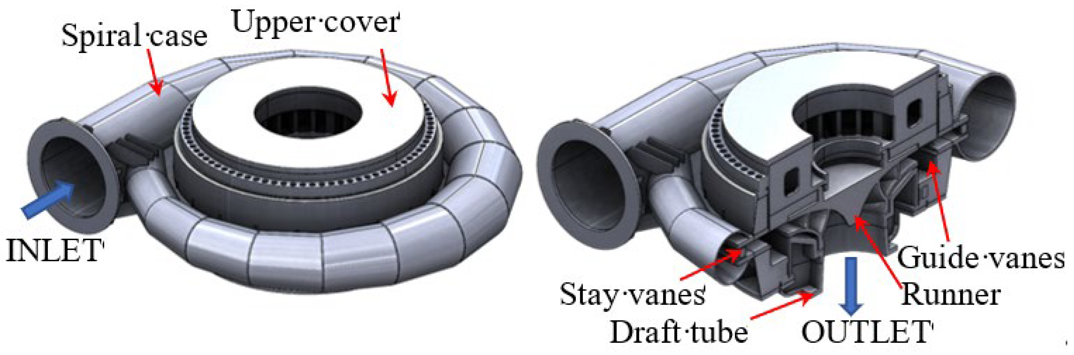
Figure 2.
Scheme of the fatigue modes.
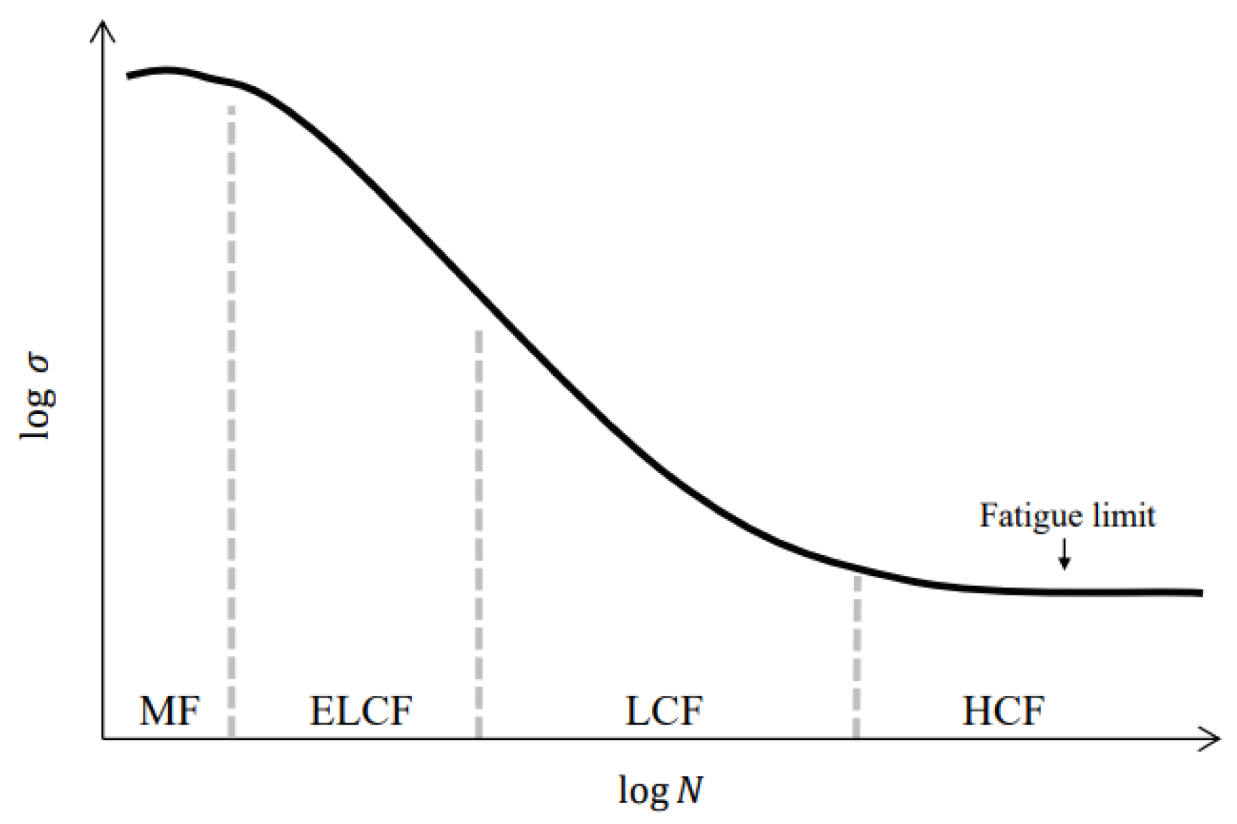
Figure 3.
Low and high cycle loads in hydraulic power plants [39].
Figure 3.
Low and high cycle loads in hydraulic power plants [39].
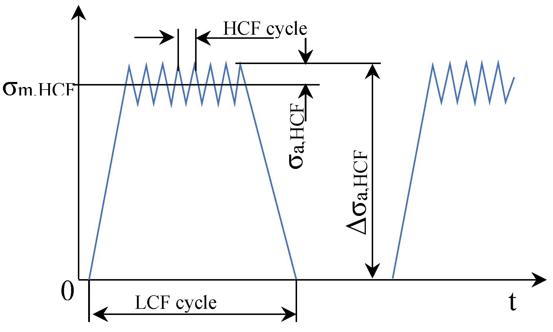
Figure 4.
The destruction of the stay vane No. 1 and the cracks.
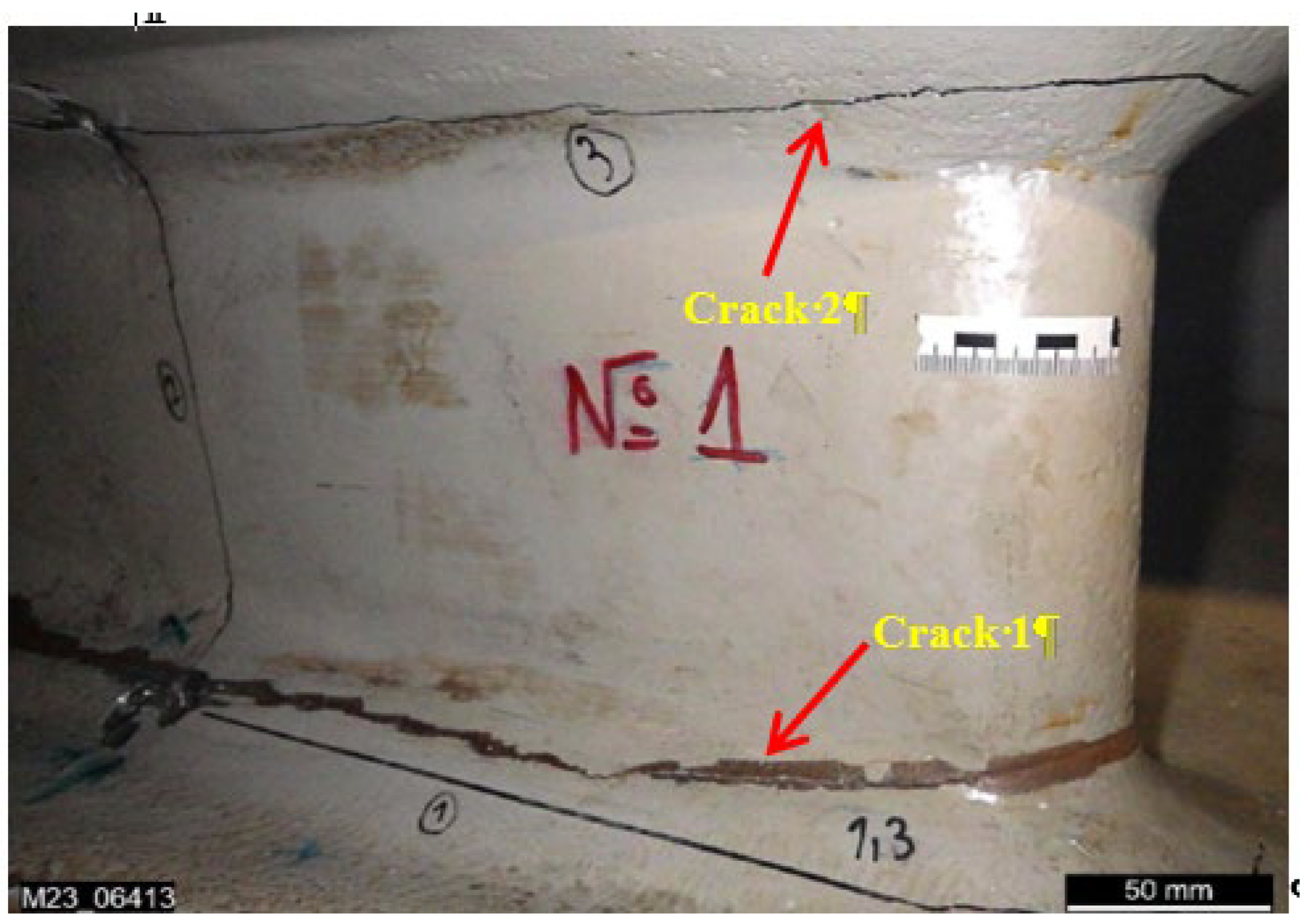
Figure 5.
Block diagram of the simulation procedure stages, the analysis and the conclusions.
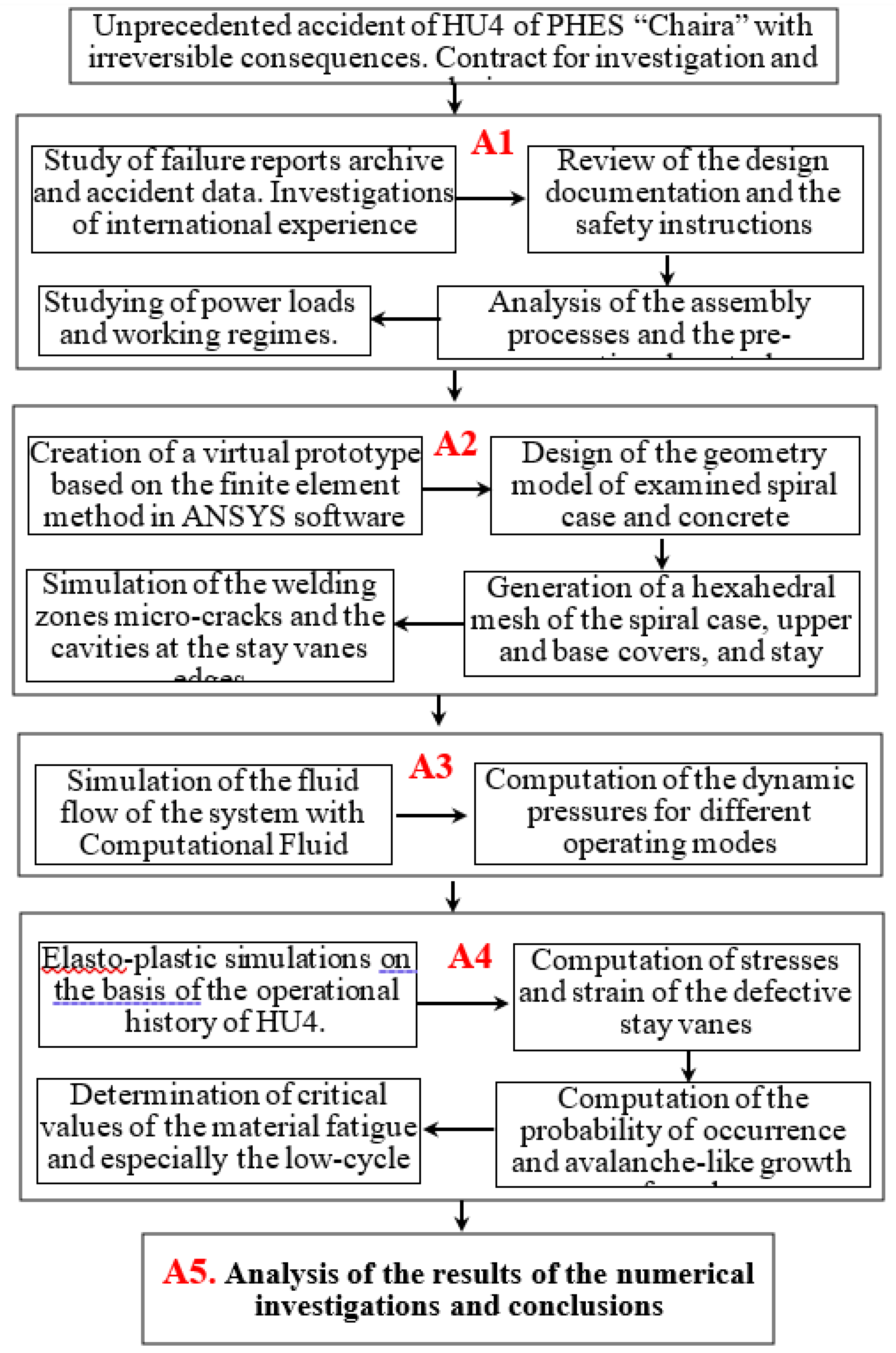
Figure 6.
Nominal and peak loads (a sample of the PHES sensors records).
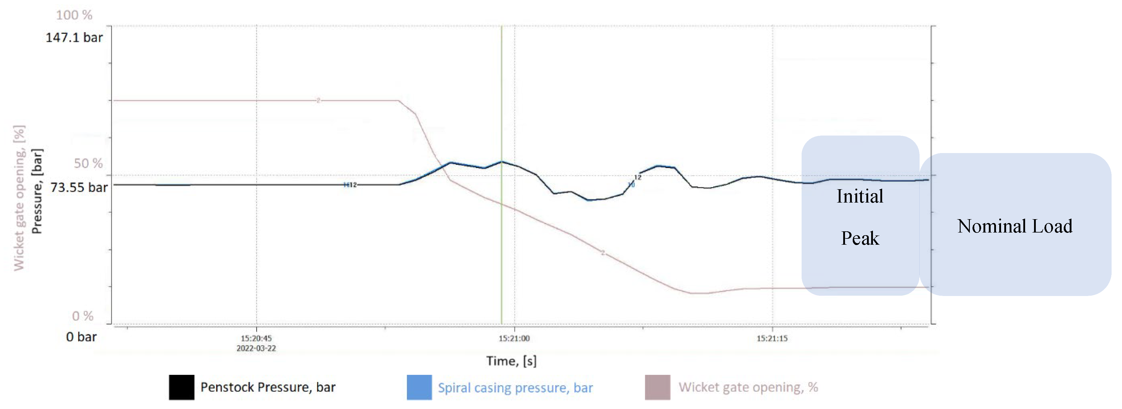
Figure 7.
Geometry model of (a) the concrete embedment; (b) metal structure of the turbine; (c) cross section of the lower part of the spiral casing and the stay vanes.
Figure 7.
Geometry model of (a) the concrete embedment; (b) metal structure of the turbine; (c) cross section of the lower part of the spiral casing and the stay vanes.
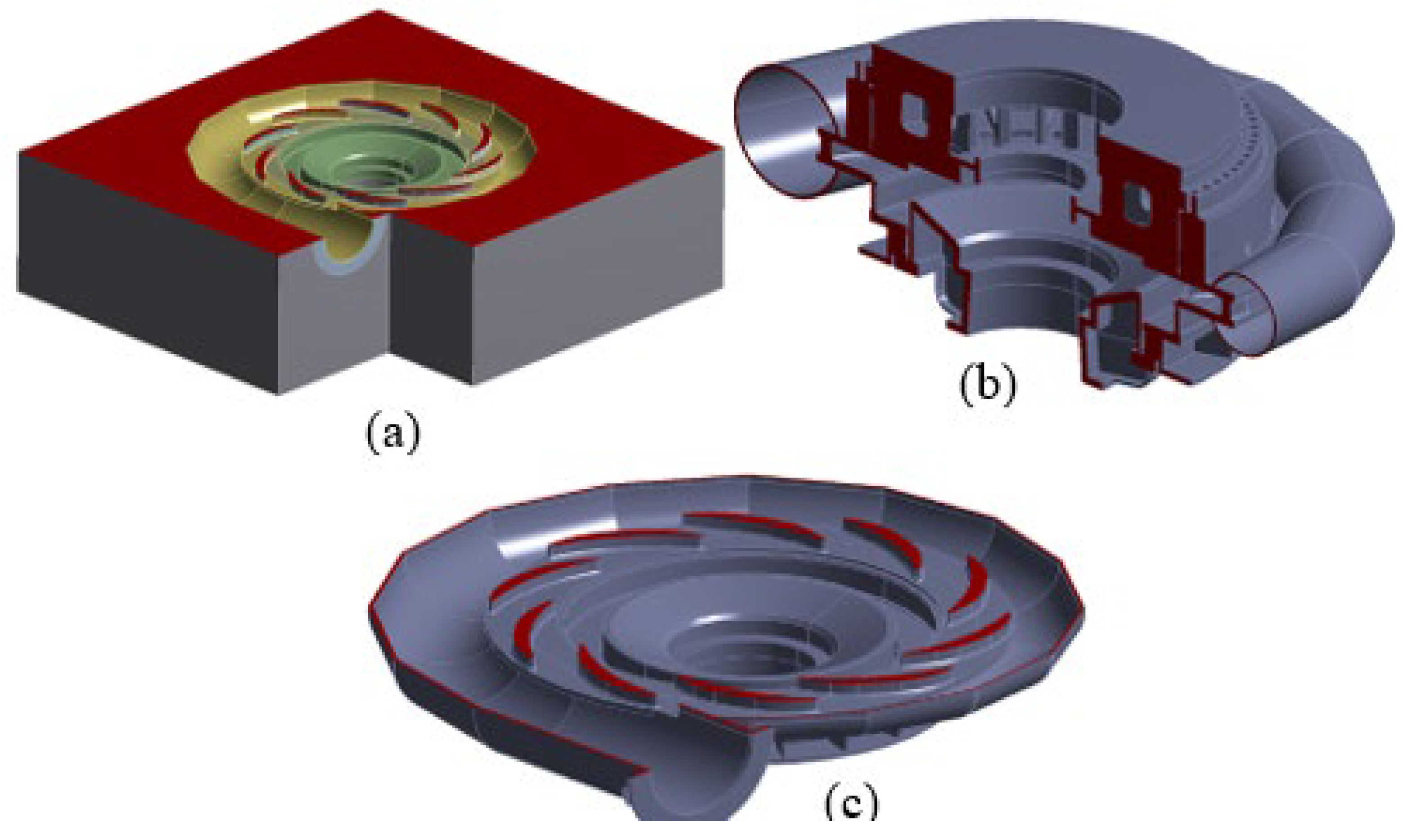
Figure 8.
Specimens of the micro-cracks from the welded zones at the stay vanes edge: (a) used specimen; (b) specimen with marked zones.
Figure 8.
Specimens of the micro-cracks from the welded zones at the stay vanes edge: (a) used specimen; (b) specimen with marked zones.
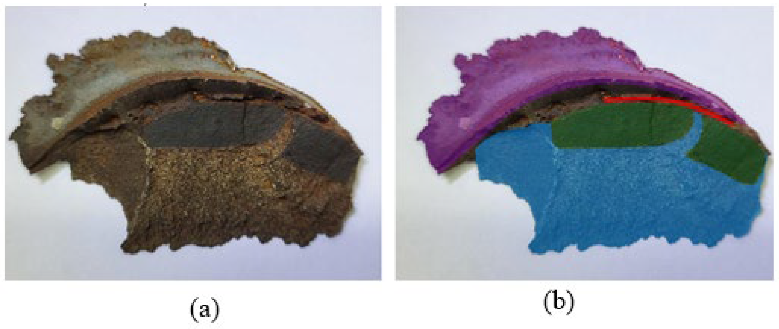
Figure 9.
Geometry model of a stay vane edge, including the welded cavity zone.
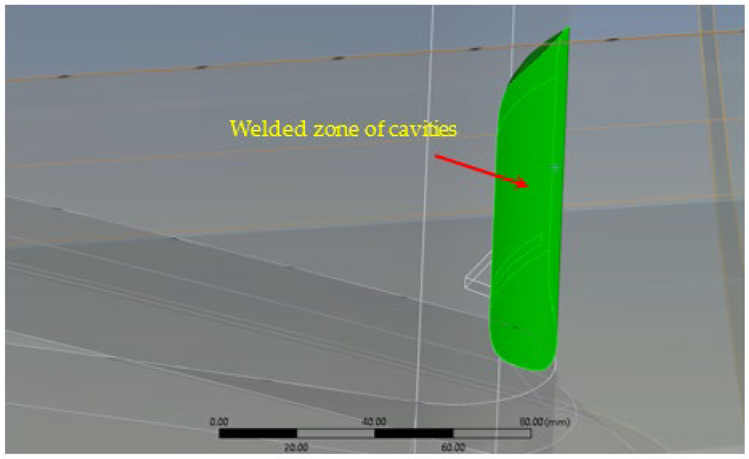
Figure 10.
Generated hexahedral mesh of: (a) the concrete embedment; (b) the turbine, the spiral casing and the concrete enforcement.
Figure 10.
Generated hexahedral mesh of: (a) the concrete embedment; (b) the turbine, the spiral casing and the concrete enforcement.
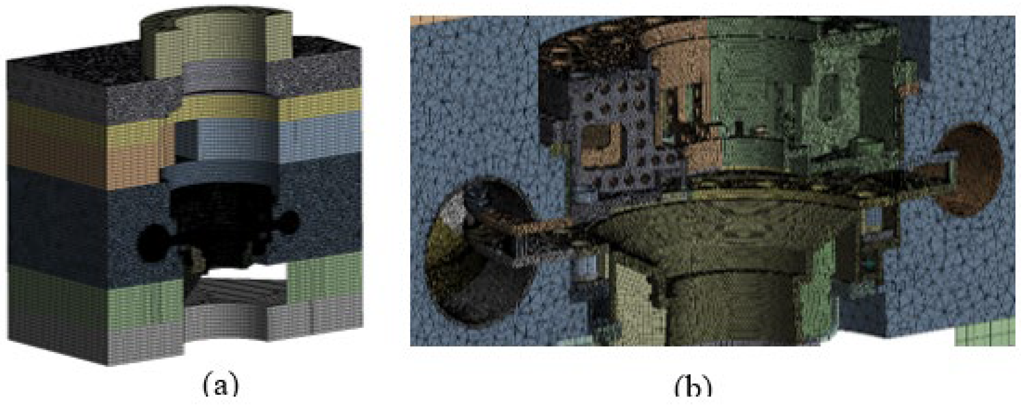
Figure 11.
Fatigue data for the materials of the stay vanes: (a) measured fatigue data; (b) approximated curve.
Figure 11.
Fatigue data for the materials of the stay vanes: (a) measured fatigue data; (b) approximated curve.
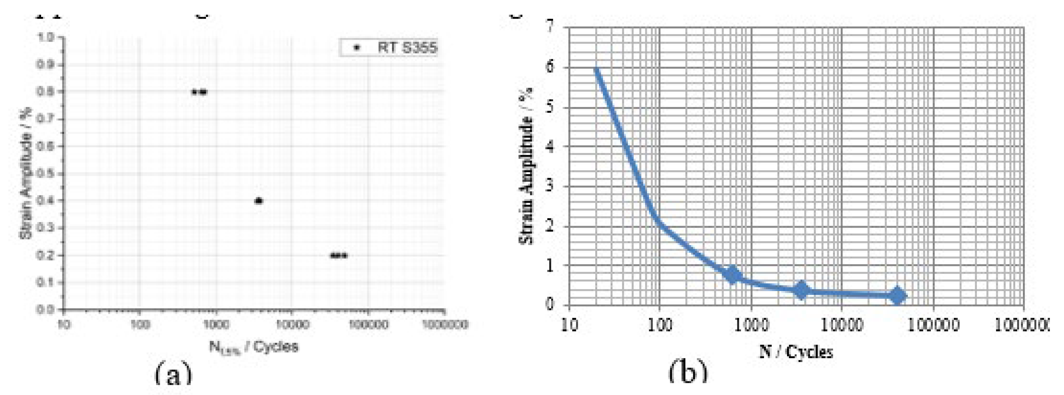
Figure 12.
Geometry and mesh model for CFD simulations: (a) full geometrical mode; (b) zoomed mesh model.
Figure 12.
Geometry and mesh model for CFD simulations: (a) full geometrical mode; (b) zoomed mesh model.
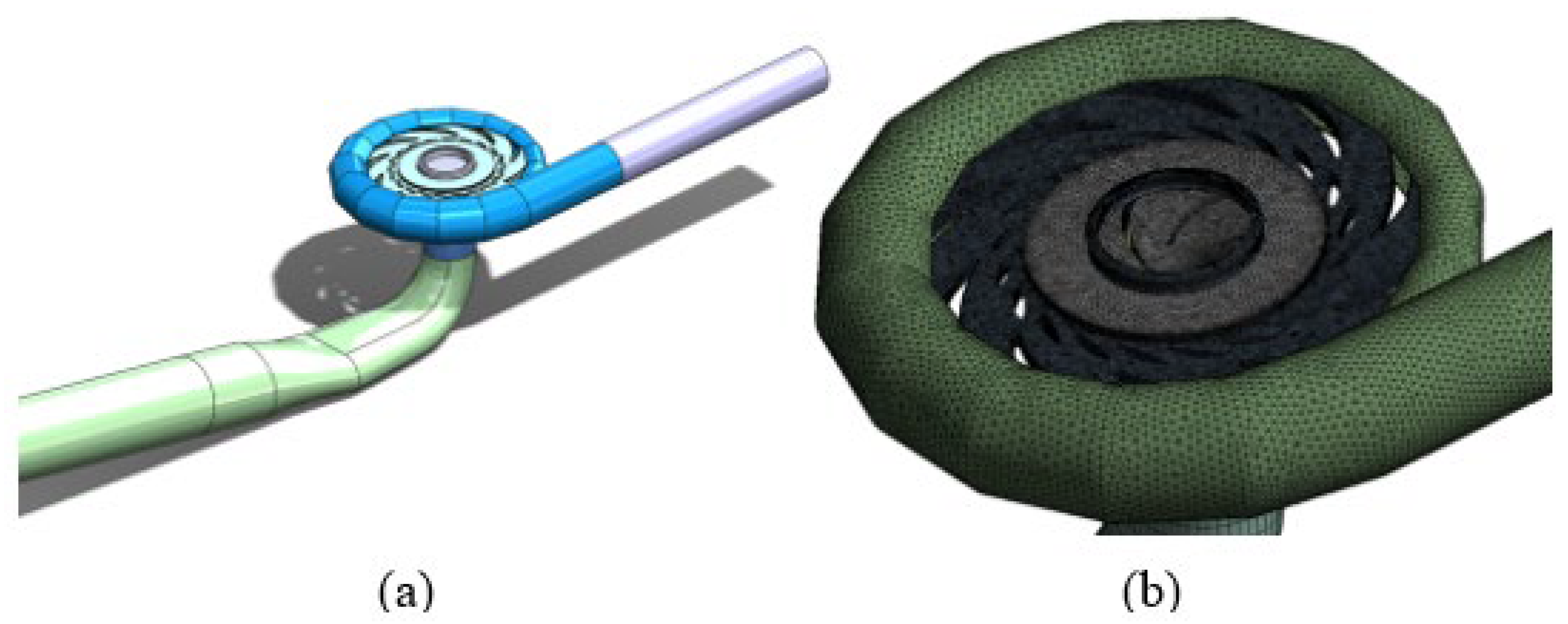
Figure 13.
S1 – fluid velocity vectors: (a) radial cross section of the spiral casing; (b) fluid tracks along the turbine outlet.
Figure 13.
S1 – fluid velocity vectors: (a) radial cross section of the spiral casing; (b) fluid tracks along the turbine outlet.
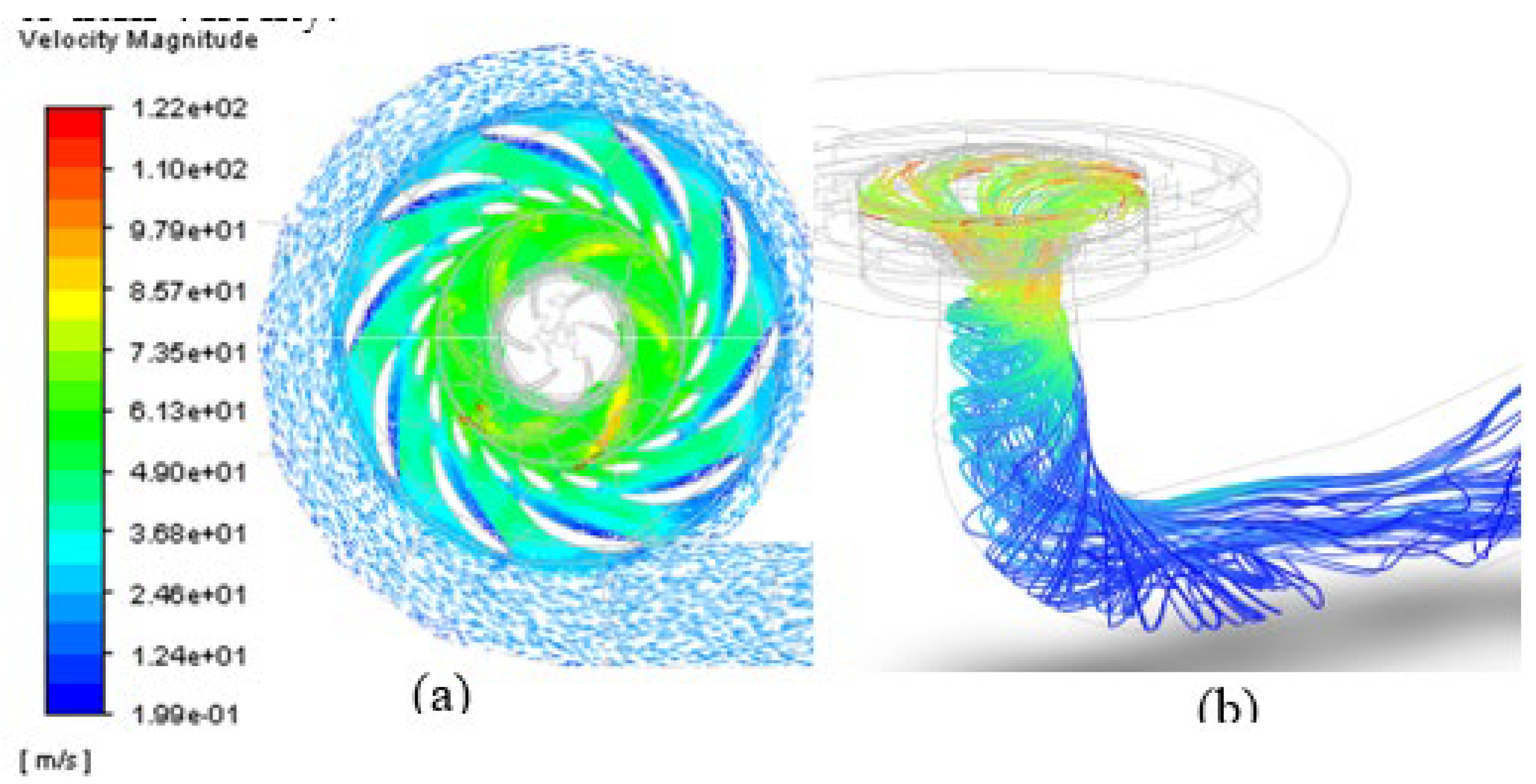
Figure 14.
S1 – total pressure distribution in two cross sections of the turbine: (a) axial cross section; (b) radial cross section.
Figure 14.
S1 – total pressure distribution in two cross sections of the turbine: (a) axial cross section; (b) radial cross section.
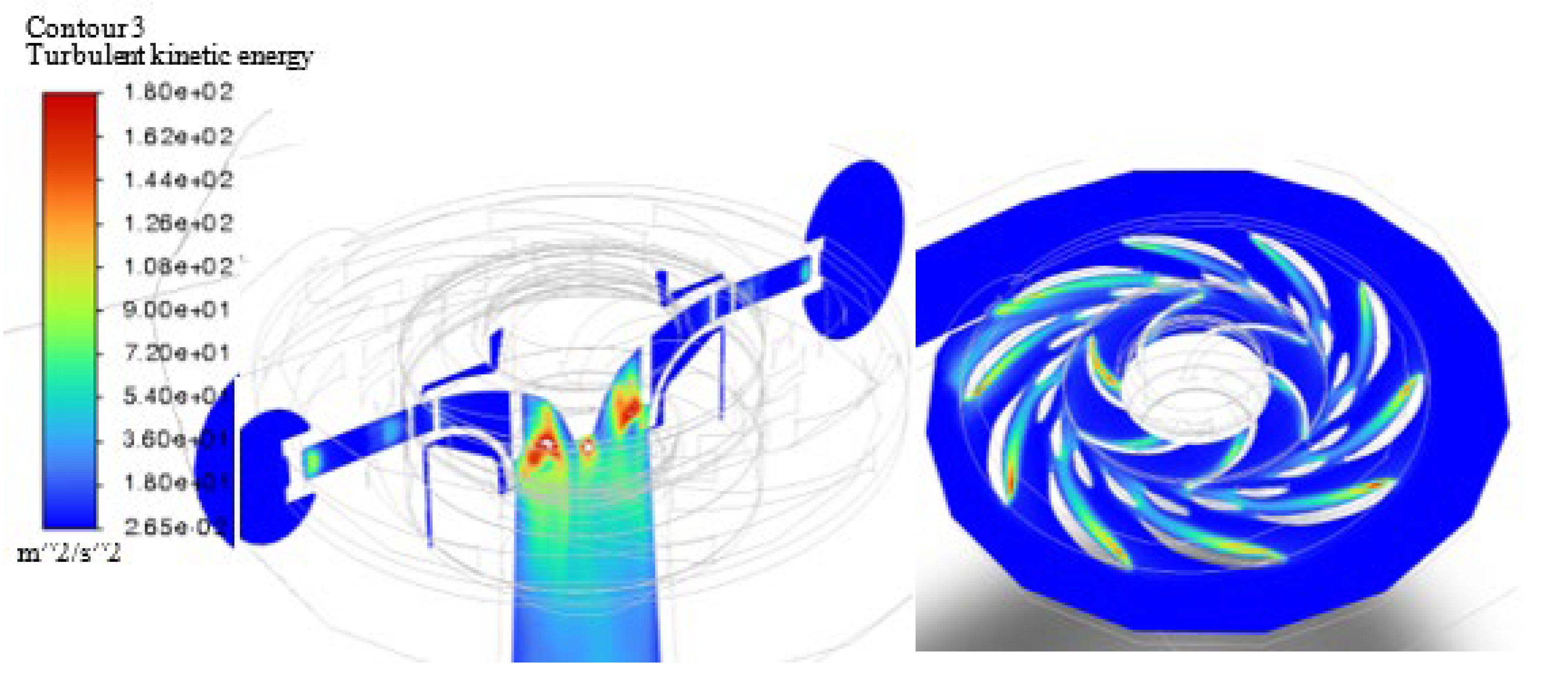
Figure 15.
S1 – axial cross section of the spiral casing and the outlet tube with the total pressure distribution.
Figure 15.
S1 – axial cross section of the spiral casing and the outlet tube with the total pressure distribution.
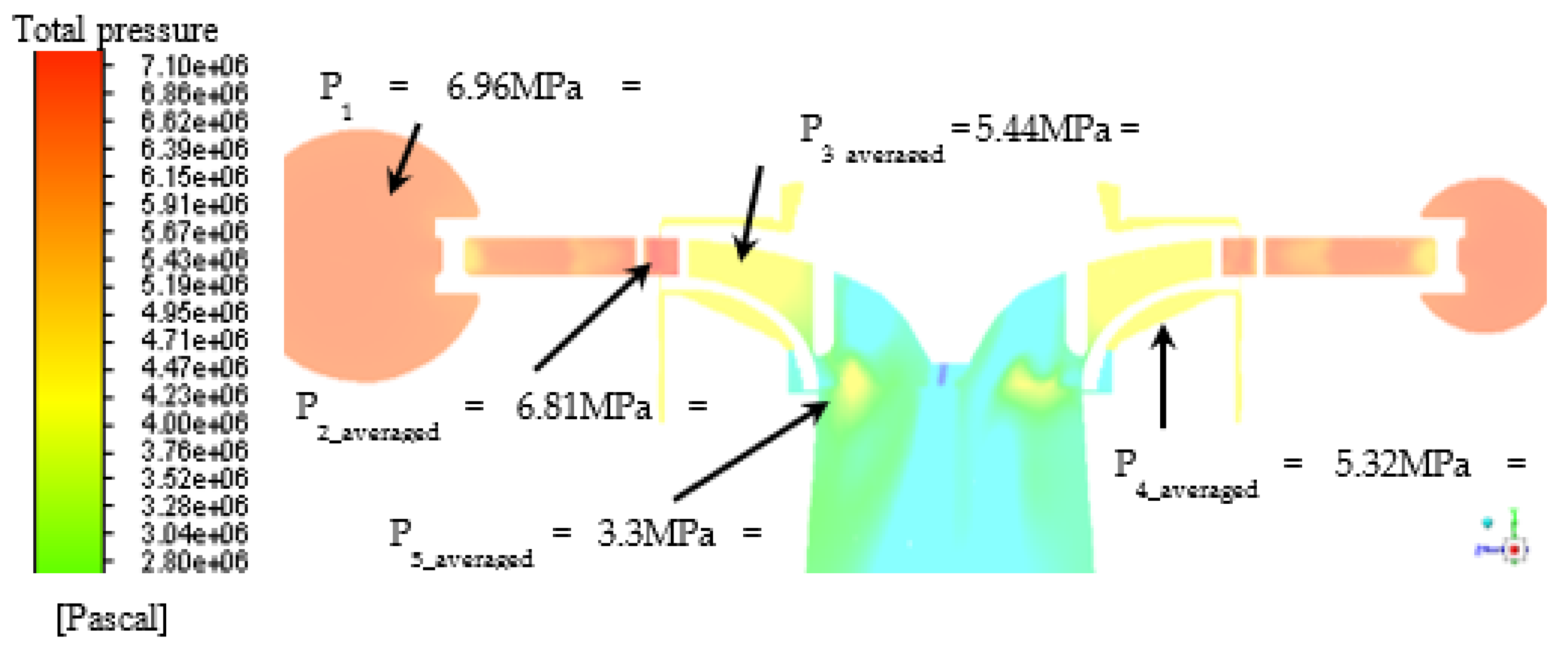
Figure 16.
S3 – the vector distribution of the fluid velocity in the radial cross section of the spiral casing.
Figure 16.
S3 – the vector distribution of the fluid velocity in the radial cross section of the spiral casing.
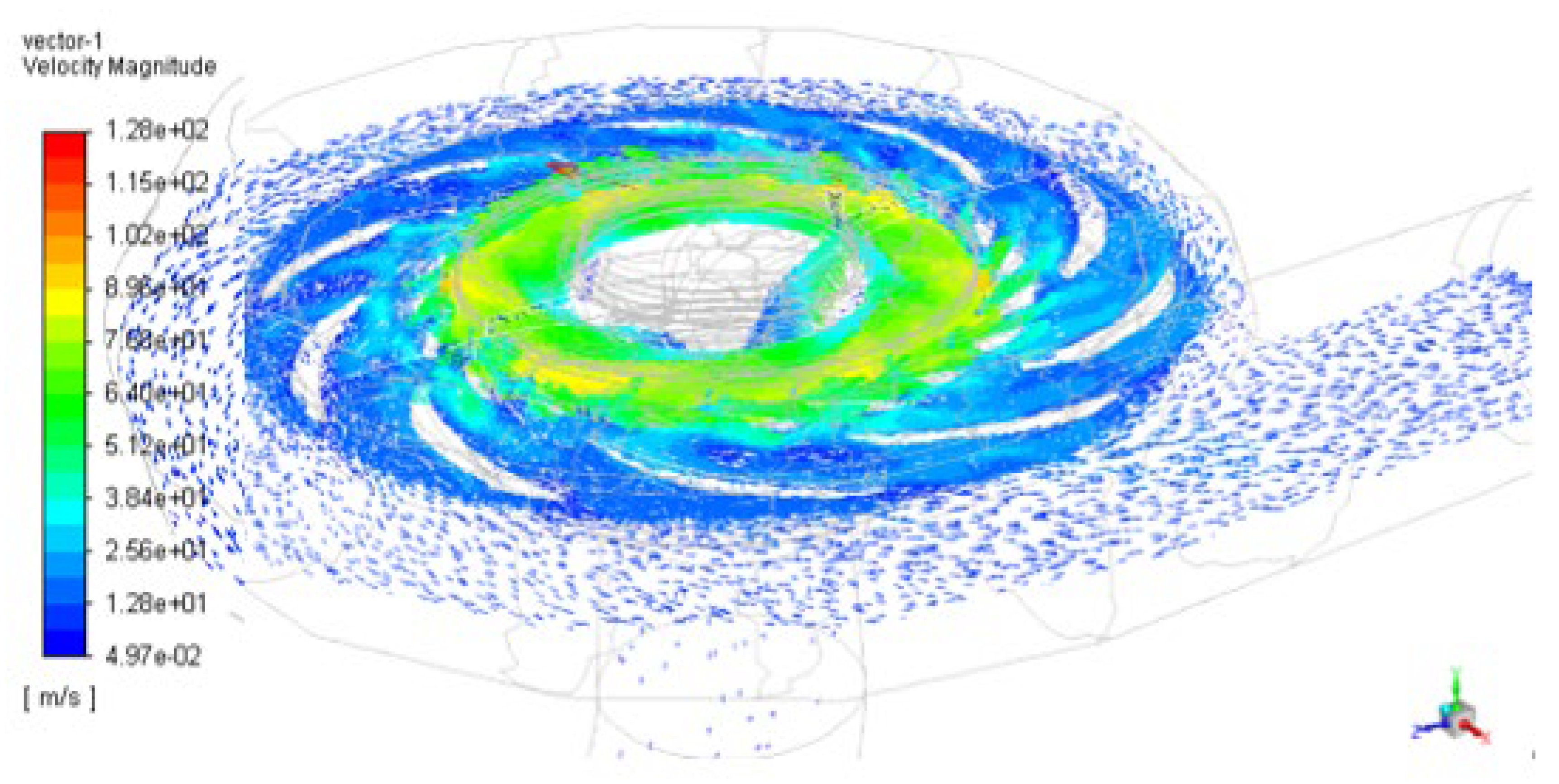
Figure 17.
S3 – the numerical values of the total pressure in the axial cross section of the spiral casing and the outlet tube.
Figure 17.
S3 – the numerical values of the total pressure in the axial cross section of the spiral casing and the outlet tube.
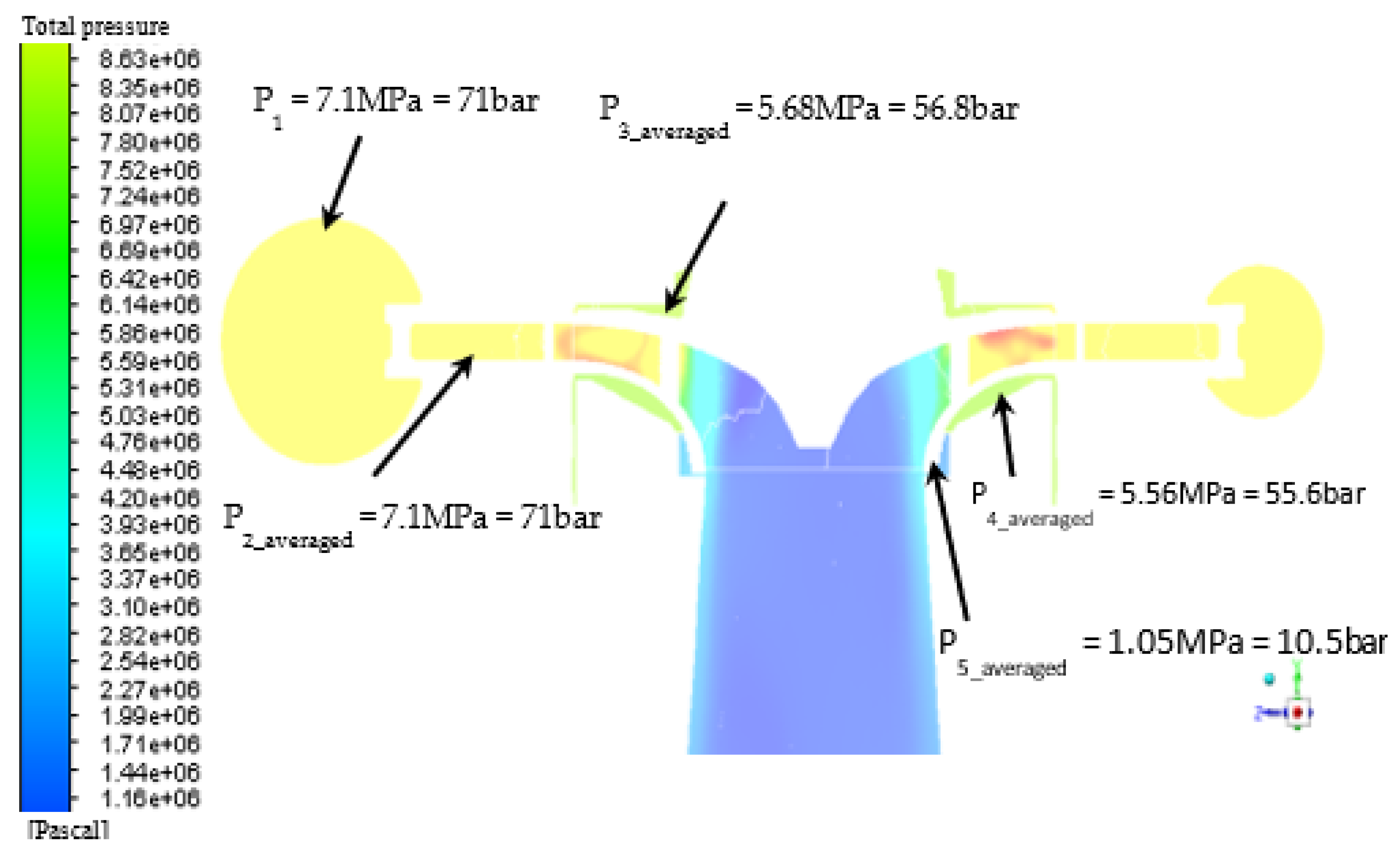
Figure 18.
S5 – the numerical values of the total pressure in the axial cross section of the spiral casing and the outlet tube.
Figure 18.
S5 – the numerical values of the total pressure in the axial cross section of the spiral casing and the outlet tube.
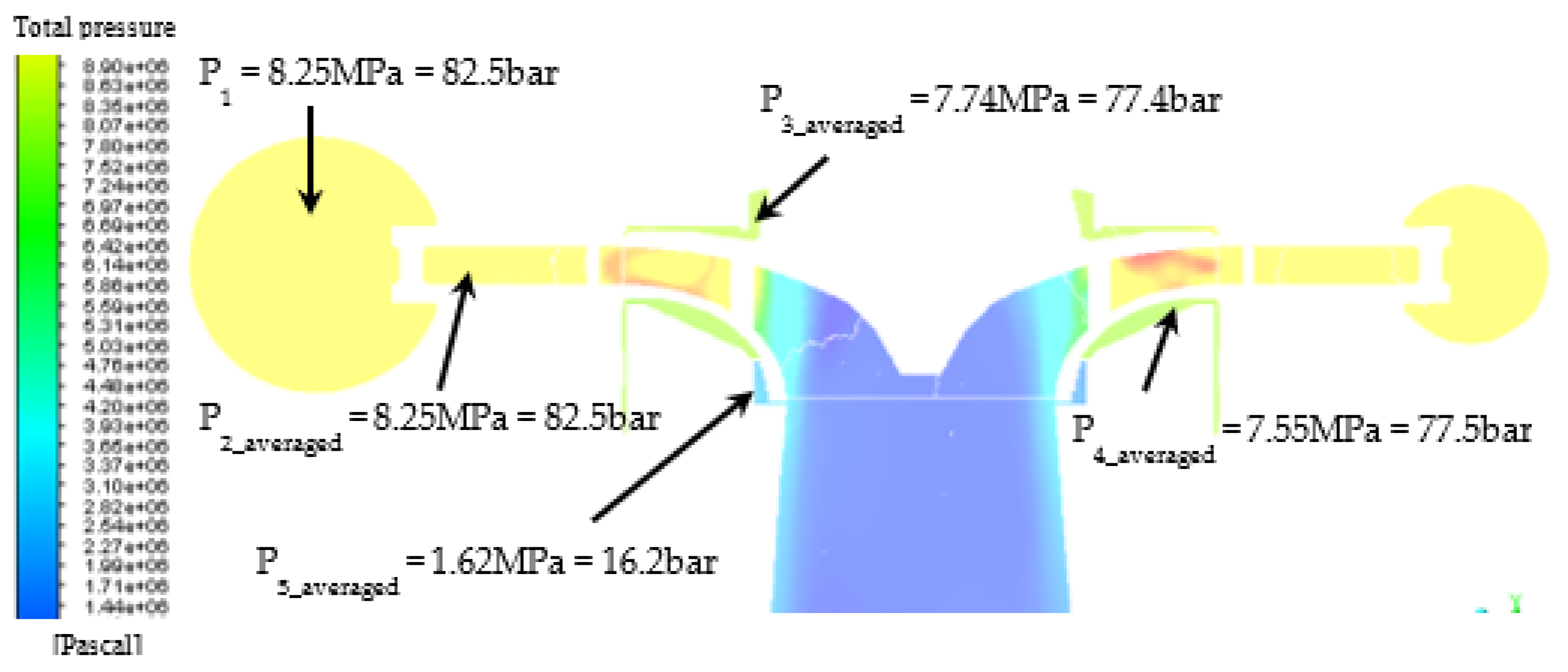
Figure 19.
S5 – the engineering analyzes for the stay vanes: (a) maximal values of the equivalent stresses of the vanes; (b) the equivalent stresses on the front edge of the sixth stay vane.
Figure 20.
S5 – the engineering analyzes for the stay vanes: (a) maximal values of the equivalent strains of the vanes; (b) the equivalent strains on the front edge of the sixth stay vane.
Figure 20.
S5 – the engineering analyzes for the stay vanes: (a) maximal values of the equivalent strains of the vanes; (b) the equivalent strains on the front edge of the sixth stay vane.
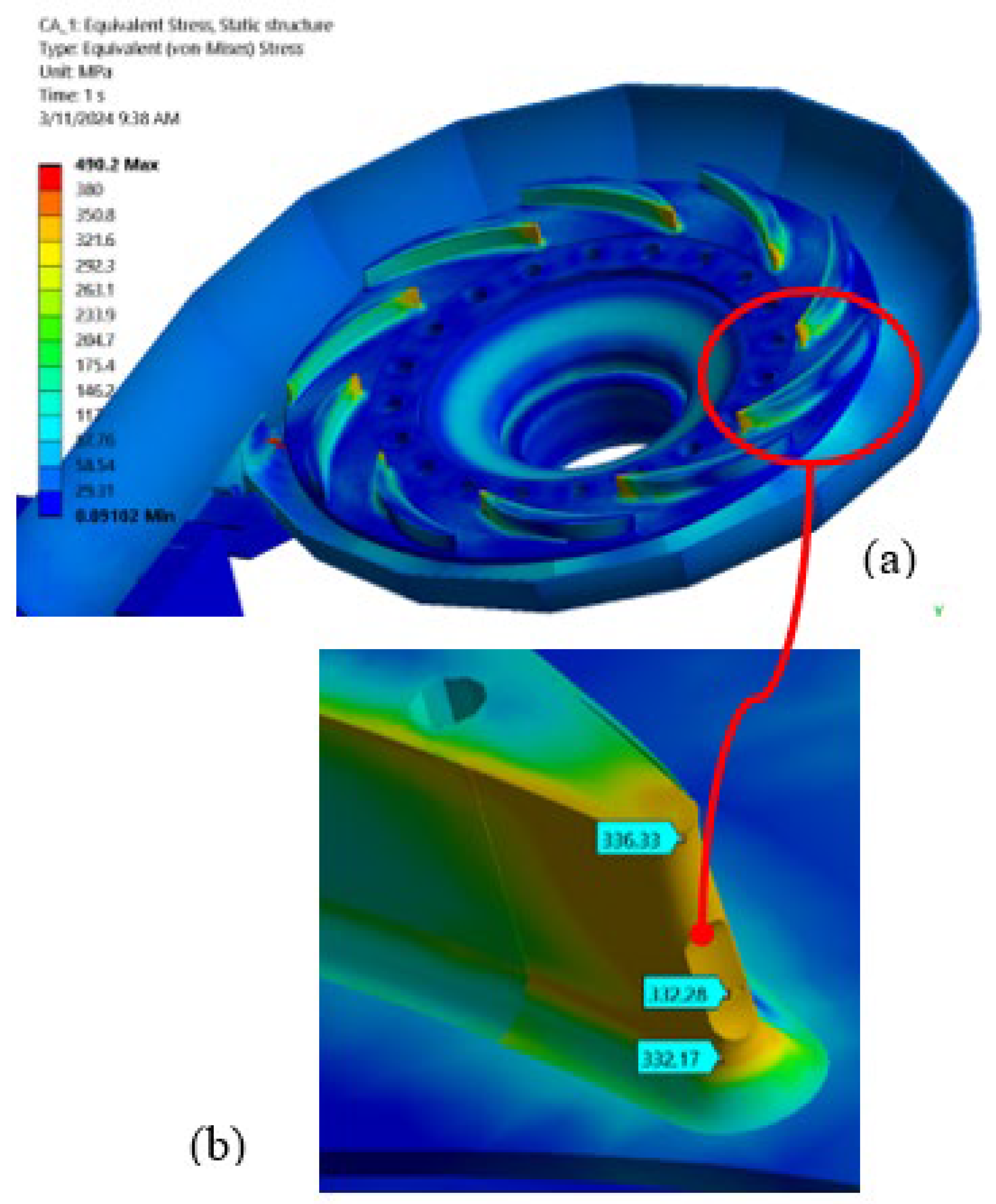

Table 1.
Number of work cycles of hydraulic unit 4 for entire exploitation period.
| Generator mode | Pump mode | Compensatory mode | Total |
|---|---|---|---|
| 3 754 | 5 021 | 3 081 | 11 856 |
Table 2.
Material properties of concrete and steel structures.
| Parameter | Steel HT60 | Steel JIS G 3106 SM50 A | Concrete B25 |
| Elasticity modulus, E, GPa | 209 | 200 | 30 |
| Poisson ratio, μ | 0.29 | 0.28 | 0.18 |
| Density, ρ, kg/m3 | 7850 | 7700 | 2400 |
| Yield strength Rp0,2, MPa | 461 | 334 | Not used |
| Tensile strength, Rm, MPa | 620 | 520 | Not used |
| Tangential modulus, MPa | 3300 | 3640 | Not used |
Table 3.
Applied boundary conditions in CFD analyses.
| Analysis | Loading mode | Pressure at the inlet of the turbine, pin, MPa | Turbine speed, nt, min-1 |
|---|---|---|---|
| S1 | Nominal generator mode | 6.96 | 600 |
| S2 | Peak at generator mode | 7.795 | 600 |
| S3 | Nominal pump mode | 7.1 | 600 |
| S4 | Peak in pump mode | 7.597 | 600 |
| S5 | Load rejection mode | 8.04 | 800 |
Table 4.
Maximal values of total deformation for examined load cases and number of cicles.
| Loading mode | ε - total deformations | N – number of cycles | |
| S1 | Nominal generator mode | 6.96 | 600 |
| S2 | Generator mode at peak in transient mode | 7.795 | 600 |
| S3 | Nominal pump mode | 7.1 | 600 |
| S4 | Pump mode at peak in transient mode | 7.597 | 600 |
| S5 | Emergency modes | 8.04 | 800 |
Disclaimer/Publisher’s Note: The statements, opinions and data contained in all publications are solely those of the individual author(s) and contributor(s) and not of MDPI and/or the editor(s). MDPI and/or the editor(s) disclaim responsibility for any injury to people or property resulting from any ideas, methods, instructions or products referred to in the content. |
© 2024 by the authors. Licensee MDPI, Basel, Switzerland. This article is an open access article distributed under the terms and conditions of the Creative Commons Attribution (CC BY) license (http://creativecommons.org/licenses/by/4.0/).
Copyright: This open access article is published under a Creative Commons CC BY 4.0 license, which permit the free download, distribution, and reuse, provided that the author and preprint are cited in any reuse.


