
Submitted:
17 October 2024
Posted:
18 October 2024
You are already at the latest version
Abstract
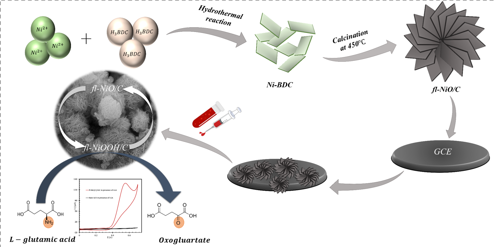
This research introduces a non-enzymatic electrochemical sensor utilizing flower-like nickel ox-ide/carbon (fl-NiO/C) microspheres for the precise detection of L-glutamic acid (LGA), a crucial neurotransmitter in the field of healthcare and a frequently utilized food additive and flavor en-hancer. The fl-NiO/C were synthesized with controllable microstructures using metal-organic frameworks (MOFs) as precursors followed by a simple calcination process. The uniformly synthe-sized fl-NiO/C microspheres were further characterized using Fourier Transform Infrared Spec-troscopy (FTIR), X-ray powder diffraction (XRD), Energy-dispersive X-ray spectroscopy (EDX), and Field Emission Scanning Electron Microscopy (FE-SEM). The fl-NiO/C was utilized as a modi-fier on the surface of a glassy carbon electrode, and an impedimetric sensor based on Electro-chemical Impedance Spectroscopy (EIS) was developed for the detection of LGA. The proposed sensor demonstrated excellent catalytic activity and selectivity towards LGA across a broad con-centration range of 10-800 μM with a sensitivity of 486.9 µA.mM-1.cm-2 and a detection limit of 1.28 µM (S/N=3). The sensor was also employed to identify LGA in blood plasma samples, yield-ing results that align with those obtained through HPLC. This achievement highlights the poten-tial of fl-NiO/C microspheres in advancing cutting-edge biosensing applications.
Keywords:
non-enzymatic
; electrochemical
; flower-like microstructure
; microsphere
; L-Glutamic acid
; neurotransmitter
1. Introduction
L-glutamic acid (LGA) exerts a decisive influence on a variety of brain functions as a principal excitatory neurotransmitter within the nervous system [1]. Disruption to LGA metabolism has been linked to a number of neurological disorders. These include stroke [2], Alzheimer’s disease [3], brain trauma [4], schizophrenia [5], epilepsy [6], and multiple sclerosis [7]. However, it is already established that LGA issues do not independently precipitate these conditions. To identify more efficacious treatments, it is necessary to examine the manner in which LGA interacts with other brain chemicals [8,9,10]. In addition to its neurological implications, LGA serves as a flavour enhancer in foodstuffs. Nevertheless, excessive consumption can result in adverse effects such as headaches and gastric distress [11]. Hence, monitoring LGA concentrations is imperative both in dietary and medical contexts.
Over the past two decades, various methods have been developed to quantify LGA such as chromatography [12], fluorometry [13], spectrophotometry [14], capillary electrophoresis [15]and electrochemical (bio)sensors [16,17,18]. Among them, electrochemical (bio)sensors have gained prominence in this field owing to their sensitivity, affordability, and easy operation. Electrochemical (bio)sensors designed for LGA detection can be divided into two categories: enzyme-based biosensors and non-enzymatic sensors. The first category of sensors employs the glutamate oxidase (GluOx) enzyme to produce hydrogen peroxide (H2O2) as a byproduct during the oxidative deamination of LGA in the presence of oxygen (O2). The production of H2O2 is directly related to the concentration of LGA [19,20]. However, enzyme-based biosensors face challenges due to the high costs of GluOx and its susceptibility to denaturation. Recently, advancements have led to the emergence of a second category of sensors that rely on the direct electrooxidation of GLA through the use of materials, which mimic the catalytic activity of GluOx. These non-enzymatic sensors are gaining popularity as an alternative to enzyme-based sensors. Transition metal/metal oxide nanomaterials and a variety of protein mediators have been employed as non-enzymatic sensing materials for the detection of LGA [21,22]. Among the materials under consideration, those based on nickel (Ni) in various forms, including nanowire [23], nickel oxide (NiO) nanoparticles [24], metal–organic frameworks (MOF), and their nanocomposites [25] have been identified as promising catalysts for LGA oxidation in an alkaline medium. This is due to their cost efficiency, electrocatalytic activity, and stability. A recent development by our research team has led to the creation of two non-enzymatic GLA sensors, utilizing two distinct synthesized materials: Ni-MOF and Ni-NiO-MOF-carbon nanocomposite. An investigation into their catalytic abilities has yielded promising results. The combination of carbon layers and MOFs forms a cavity-like network structure, which subsequently develops into a porous network. This structure enhances the electrocatalytic effect of Ni and NiO compared to the sheet-like structure of Ni-MOF [26]. This indicates that the creation of porous three-dimensional (3D) materials enhances the electrocatalytic activity of Ni-based materials.
In this context, the flower-like Ni structures have been the subject of considerable interest due to the extensive three-dimensional surface area that provides abundant space for redox reactions in electrochemical processes [27]. In particular, the fabrication of flower-like Ni derivatives based on the use of MOF as a precursor enables the creation of an adjustable porous 3D nano/micro structure [28]. Subsequently, a simple calcination process under atmospheric conditions can produce metal oxides from their corresponding MOFs, resulting in materials with inherited or identical morphologies [29].
In this investigation, we successfully synthesized porous 3D flower-like nickel oxide/carbon (fl-NiO/C) microstructures using nickel-benzene dicarboxylate (Ni-BDC) MOF as a precursor. Subsequently, nanosheets of Ni-MOF underwent a morphological transition during calcination, transforming into flower-like NiO microspheres. The fl-NiO/C were then employed to develop a straightforward non-enzymatic sensor for LGA detection on a glassy carbon electrode (GCE). The sensor was characterized using multiple electrochemical techniques. For selective and sensitive detection of LGA across a wide linear range, Electrochemical Impedance Spectroscopy (EIS) was used as an alternative to traditional methods like amperometry and differential pulse voltammetry. The proposed system exhibited satisfactory sensing performance, including a low detection limit, a wide dynamic range, optimal sensitivity, and suitability for measuring LGA in real samples.
2. Experimental Section
2.1. Reagent and Materials
Chemical reagents, including Benzene-1,4-dicarboxylic acid (H2BDC), nickel nitrate hexahydrate (Ni(NO3)2.6H2O), L-glutamic acid, glucose (Glu), uric acid (UA), ascorbic acid (AA), and sodium hydroxide (NaOH), were purchased from Sigma Aldrich. N,N-dimethylformamide (DMF) and ethanol were obtained from Merck. The chemicals were used as received without further purification. All solutions were prepared using deionized double-distilled water, and each chemical solution was freshly prepared before the experiment. Human blood plasma was obtained from the Pars Laboratory, Yazd, Iran.
2.2. Equipment
Fourier Transform Infrared Spectroscopy (FT-IR) using a BRUKER EQUINOX 55 single beam spectrometer, X-ray powder Diffraction (XRD) using D8 Advance Bruker and Cu Kα radiation (λ = 1.54 Å) (Germany), Energy-dispersive X-ray spectroscopy (EDS) (model EM8000F, China), and Field Emission Scanning Electron Microscopy (FE-SEM) using MIRA3G Tescan were employed to characterize the synthesized the fl-NiO/C. To evaluate the electrochemical properties of the prepared electrodes, we utilized an Autolab potentiostat/galvanostat (PGSTAT-302 N, Eco Chemie, and The Netherlands) with a standard three-electrode setup: modified GCE as the working electrode, platinum wire as the counter electrode, and Ag/AgCl/KCl (Sat.) as the reference electrode.
2.3. Preparation of Ni-BDC MOF as a Precursor
Ni-BDC MOF was synthesized using a typical solvothermal procedure [30]. Specifically, Ni (NO3)2.6H2O (0.564 g, 1.8 mmol) and H2BDC (0.262 g, 1.2 mmol) were separately dissolved in 10 mL of DMF at room temperature using magnetic stirring. Afterward, the Ni (NO3)2 solution was added gradually to the H2BDC solution and stirred for 30 minutes. Then, the resulting solution was placed in a Teflon-lined autoclave (50 mL) and heated at 150°C for 12 hours. The light green precipitate was collected through centrifugation, washed thrice with ethanol and water, and then dried at 80°C overnight.
2.4. Preparation of fl-NiO/C Microsphere
The one-step calcination process was employed to synthesize fl-NiO/C microspheres. Initially, the Ni-BDC powder was ground and placed in a tubular furnace. The subsequent annealing process was carried out at 500°C (heating rate of 5°C/min) in the air for two hours. Following this, the black powder was collected after cooling back to room temperature.
2.5. Preparation of fl-NiO/C/GCE
To prepare the modified GCE with fl-NiO/C, a GCE with a surface area of 0.03 cm2 was polished first using 0.3 μm alumina powder, followed by rinsing with deionized water. Thereafter, it was immersed in a solution containing water and ethanol in a ratio of 1:1, and sonicated for 10 minutes. Subsequently, 2 μL of the fl-NiO/C suspension (5mg/mL in ethanol) was dropped on the clean surface of the GCE and was allowed to air dry at room temperature. The resulting sensor was designated as fl-NiO/C/GCE.
3. Results and Discussion
3.1. Material Characterization
To analyze the structural and compositional properties of the synthesized Ni-BDC MOF as precursor and the fl-NiO/C microsphere, FTIR and X-ray diffractometry (XRD) techniques were employed. The XRD patterns of Ni-BDC and fl-NiO/C microsphere are shown in Figure 1A. The major diffraction peaks of Ni-BDC were observed at 2θ of 15.15, 16.03, and 17.23, corresponding to the (001), (10-1), and (2-10) crystal planes, which were assigned to Ni-MOF and matched well with CCDC no. 638866, as previously reported [31]. Following the calcination of Ni-BDC, the XRD pattern of fl-NiO/C showed diffraction peaks at 37.2°, 43.3°, 63.0°, 75.6° and 79.5°, which are attributed to the (111), (200), (220), (311) and (222) planes of face-centred cubic nickel, respectively. These peaks are consistent with the standard NiO spectrum (JCPDS, No. 47-1049) [32]. In addition, FTIR characterisation of Ni-BDC and fl-NiO/C (Figure 1B) has been carried out as confirmation of their successful synthesis. The FTIR spectrum of Ni-BDC displayed two distinct peaks at approximately 1575 and 1381 cm-1, which correspond to the asymmetric and symmetric stretching modes of the coordinated carboxylate (–COO−) groups of the BDC ligands, respectively [31].
Similarly, in the case of fl-NiO/C, the absorption peaks detected at around 3427, 1600, and 1402 cm−1 are assigned to O−H stretching vibration, symmetric and asymmetric –COO− stretching vibrations, respectively. Moreover, the peak observed at 439 cm-1 is attributed to Ni−O vibration absorption in fl-NiO/C, which is consistent with absorption bands of metal oxides below 1000 cm-1 due to interatomic vibrations [33].
Further information on the morphology of the microstructures was obtained from the FE-SEM and EDS results. In the FE-SEM images, it can be observed that Ni-BDC MOF consists of numerous sheet-like structures having micro width and nano thickness, as depicted in Figure 2 (A, B and C). Upon heat treatment, these sheet-like structures entangled with each other and formed microspheres resembling flowers, as seen in Figure 2 (D, E, and F). Upon magnification of the images, it was observed that the surfaces of the microspheres were significantly rough due to being covered by a large number of cross-linked nanosheets. In the following step, EDX technique was used for the elemental analysis and chemical characterization of samples. The result of the EDX analysis showed the presence of Ni, O, and C elements in both Ni-BDC and fl-NiO/C (as shown in Figure 3 A and B). Ni and C were found to have a similar distribution pattern in Ni-BDC MOF. Upon further investigation of the fl-NiO/C mapping, it was observed that the regions were rich in Ni and O and contained lower amounts of C, which could be due to the NiO coating in these areas.
3.2. Electrochemical Behaviour of the fl-NiO/C/GCE
Cyclic voltammetry and EIS were used to study the electrochemical behaviour of fl-NiO/C microspheres. To determine and compare the active surface area of fl-NiO/C/GCE with that of the bare GCE, cyclic voltammograms (CV) of both bare and fl-NiO/C/GCE were recorded in 0.1 M KCl containing 5.0 mM [Fe (CN)6]3-/4- as redox probe at various scan rates (Figure S1). The active surface area of the electrodes was determined by employing the Randles–Sevcik equation and utilising the resulting slope of the plot of the current versus the square root of the scan rate ( 1/2) [34] :
where (I) is the oxidation peak current, (A) is the surface area of the electrode, (n) is the electron transfer number, (D) is the diffusion coefficient of [Fe (CN)6]3-/4-, (C) is the concentration of [Fe (CN)6]3-/4-, and () is the scan rate. The calculated surface areas for bare and modified electrodes were 0.035 and 0.093 cm2, respectively. This result indicates that the incorporation of fl-NiO/C significantly enhanced the electrode’s active surface area.
The surface coverage of the electrode, , was estimated using the following equation, which employs the Sharp method [35], whereby the peak current can be directly proportional to the concentration of electroactive species on the electrode surface:
The n represents the number of electrons involved in a reaction, while A is the active surface area (0.093cm2) of the fl-NiO/C. The symbol (mol/cm2) represents the surface coverage, and the other symbols have their usual meanings. From the slope of anodic peak currents versus scan rate (as shown in Figure S2), the surface concentration of fl-NiO/C was calculated to be =11.49×10⁻⁹ mol/cm2 when n=1.
To assess the changes in electrical properties and electron transfer following the modification of the GCE, and to confirm the modification’s effectiveness, CVs and EIS spectra were recorded for both the bare GCE and the fl-NiO/C/GCE in 0.1 M KCl containing 5.0 mM [Fe(CN)6]3-/4- (Figure 4 A and B, respectively). As illustrated in Figure 4A, the bare GCE exhibited a pair of characteristic redox current peaks at 0.17 V and 0.22 V, resulting from the ferro- and ferricyanide redox reactions. In comparison, the fl-NiO/C/GCE exhibited a markedly enhanced redox peak current. The results of EIS confirmed the CV results, as demonstrated in Figure 4B. The charge transfer resistance at the electrode/electrolyte interface (Rct) value for the bare GCE was 326.1 Ω, which decreased to 218.3 Ω when modified by fl-NiO/C microspheres. These findings designate that the porous 3D structure of fl-NiO/C microspheres facilitates the creation of a larger electrochemically accessible surface area, which allows for more electron transfer pathways and enhanced electrical conductivity.
The electrocatalytic behaviour of fl-NiO/C/GCE towards LGA was analyzed in 1 M NaOH solution via cyclic voltammetry, employing a scan rate of 50 mV/s. As shown in Figure 4C, in the absence of LGA, the bare GCE is relatively inactive within a specific potential range and does not show any significant signals. On the other hand, the fl-NiO/C/GCE exhibits clear redox peaks at potentials of 0.32 V (anodic) and 0.23 V (cathodic). Two distinct theories have been proposed to explain the observed redox peaks. One theory suggests that these peaks arise from the oxidation of Ni2+ to Ni3+ and its corresponding reduction [36]. An alternative interpretation, as proposed by Jamal et al., indicates that the anodic peak results from the oxidation of NiO to NiOOH, while the cathodic peak represents its subsequent reduction [24]. The elemental characterization of fl-NiO/C, obtained from EDX and XRD analyses, showed that the microspheres are predominantly composed of NiO, supporting the second hypothesis that the electrochemical behaviour is due to the conversion of NiO to NiOOH and vice versa. Figure 4D shows the performance of bare GCE and fl-NiO/C/GCE in the presence of 1 mM LGA. Upon the addition of LGA, the bare GCE did not exhibit any response to LGA, as LGA cannot readily undergo the electron transfer at the surface of a bare electrode, even when subjected to a significantly higher voltage. In contrast, the presence of LGA resulted in a significant increase in the anodic peak current (Ipa) of fl-NiO/C/GCE, from 4 to approximately 130 µA. Conversely, the cathodic peak becomes undetectable. This suggests that fl-NiO/C is involved in a catalytic process in alkaline media, as previously observed for nickel and nickel oxide-modified electrodes [37,38,39]. As observed, the anodic peak has undergone a slight shift to a higher potential, which is attributed to the restricted diffusion of LGA towards the electrode, a phenomenon that has been previously reported [24,40,41].
The mechanism of LGA oxidation by fl-NiO/C microspheres can be illustrated through the following reactions:
To obtain more information about the electrochemical mechanism, a series of CVs were conducted at different scan rates, ranging from 10 to 70 mV/s (Figure 5A). As the scan rates increased, the oxidation peak potential was observed to shift slightly towards a more positive potential. This shift confirmed that the electrochemical reaction was kinetically limited. In correspondence with the Randles–Sevick equation [42], a plot of Ipa versus the square root of scan rate (υ 1/2), in the range of 10-70 mV/s, was obtained (Figure 5B). The linear enhancement LGA oxidation current to the υ 1/2 and linear relationship between log I and log υ with a slope value of 0.39 (that is near the theoretical value of 0.50), as displayed in Figure 5C, implying that the reaction was controlled by diffusion. Additionally, a graph of the normalized current (I/ 1/2) against the scan rate (inset shown in Figure 5A) displayed the typical EC’ process characteristics [34]. The Tafel region from the rising part of the CV voltammogram at the scan rate of 10 mV/s was selected to obtain a Tafel plot E vs log Ipa (Figure S3). In this area, oxidation was only influenced by electron transfer kinetics. By utilizing the Tafel slope equation (slope=2.3RT/(nf(1-α))), the value of the transfer coefficient (α) was determined to be 0.43. Meanwhile according to Laviron’s equation (details are in the Supporting Information), the number of electrons in the LGA oxidation reaction was obtained from the slope of the E versus log υ plot (Figure 5D) as 0.90 ≈ 1.0, indicating that one electron is involved during the electrocatalytic oxidation of LGA.
3.3. Chronoamperometric Measurements
Chronoamperometry experiments were further conducted to estimate the catalytic rate constant (k) and the diffusion coefficient (D) of LGA at the fl-NiO/C/GCE surface. The current time profiles were obtained for varying concentrations of LGA (0, 250, 500, 700, and 1000 μM) in 1M NaOH solution (Figure 6). The working electrode’s potential was adjusted to 0.6 V. According to the Cottrell equation, D of LGA can be determined by plotting the current (I) versus the square root of time (t1/2). The experimental plots for different concentrations of LGA are shown in Figure 6 inset (a), which have been fitted accordingly. After plotting the slopes of the lines against the LGA concentration (Figure 6 inset b), the resulting slope enabled the calculation of an average value for D, which was found to be 1.49×10⁻⁶ cm2.s-1. Moreover, based on the Galus method, k for the oxidation of LGA at the fl-NiO/C/GCE surface was calculated using the following equation:
where is the catalytic current of LGA at the fl-NiO/C/GCE, represents the limited current in the absence of LGA, and where is the bulk concentration of LGA. When approaches 2, the error function is nearly equal to 1. In such cases, the aforementioned equation can be simplified as follows:
To determine the rate constant value of the catalytic process, was plotted against t 1/2 for various concentrations of LGA, as shown in Figure S4. The slopes of the resultant plots were then used to calculate an average value for k, which was found to be 5.212 ×10³ M-1.s-1.This value confirms that fl-NiO/C film provides rapid electron transfer for the oxidation of LGA.
3.4. Electrochemical Impedance Spectroscopy (EIS) Measurements
EIS has recently emerged as a promising alternative to amperometry and differential pulse voltammetry for the development of sensitive, enzyme-free impedimetric biosensors, particularly for biomolecule detection at low concentrations [43,44]. The sensor functions by tracking changes in Rct in relation to the target molecule concentration, offering a reliable approach to the detection of analytes. In this study, EIS was further utilized to evaluate the effectiveness of fl-NiO/C/GCE as an LGA impedimetric sensor in a frequency range of 100 kHz to 0.1 Hz. The oscillation amplitude was set to 10 mv, and the working potential was adjusted at 0.45 V vs Ag/AgCl. The Nyquist plots of the fl-NiO/C/GCE in 1 M NaOH for various LGA concentrations are shown in Figure 7A. As can be seen, the Rct magnitude decreases gradually with the addition of concentrations ranging from 10.0 to 800.0 µM LGA. The inset of Figure 7A, illustrate the modified Randles equivalent circuit (MREC), which is used for EIS data fitting. The MREC consist of four elements. (i) The solution resistance (Rs), (ii) the double-layer capacitance (Cdl), (iii) Rct, and (iv) the Warburg resistance (ZW), which is attributed to the analyte diffusion processes. The calibration curve plotting the logarithmic effect of LGA concentration addition on the Rct response of the fl-NiO/C/GCE sensor is depicted in Figure 7B.
Accordingly, the linear fit for the Rct of LGA follows the equation Rct = -1337.6 (log [LGA]) + 2922.1 in the 10-100 µM and Rct = -187.66 (log [LGA]) + 615.21 in the 100-800 µM. The detection limit and sensitivity in the lower concentration ranges were obtained as 1.28 µM (S/N=3) and 428.98 µA.mM-1.cm-2, respectively. These results demonstrate that EIS is not only comparable to commonly used methods such as amperometry and differential pulse voltammetry, but also offers greater sensitivity, with a lower detection limit and a broader linear concentration range towards LGA detection. A comparison of the data presented in Table 1 [19,21,23,24,45,46] shows that the fl-NiO/C/GCE impedimetric sensor exhibits superior analytical performance compared to previous studies.
3.5. Interference Study of Biosensor
The sensor’s selectivity was evaluated by testing the electrode in the presence of common oxidative species such as glucose (Glu), ascorbic acid (AA), and uric acid (UA), often found alongside LGA in biological environments. The impedimetric responses of fl-NiO/C/GCE in a 1M NaOH solution including standard concentrations of UA (0.4 mM), AA (0.1 mM), and Glu (5.0 mM) alongside LGA (60 µM). Using a straightforward equation, Rct(mix) - Rct(LGA) / Rct(LGA), the EIS assessments of these interferences were examined, indicating the highest interference levels in the recognition of LGA with UA and Glu (2.8% and 5.7%, respectively), while AA exhibited an interference rate of 1.3%. These findings highlight the significance of the developed sensor in accurately detecting of LGA (as shown in Figure 8).
3.6. Stability, Reproducibility and Repeatability
The stability of the fl-NiO/C/GCE in detecting 200μM LGA was examined using amperometry through monitoring the sensor’s response for 600 seconds before and after the introduction of LGA. The findings illustrated in Figure S5 indicate that the sensor maintained nearly 97% of its initial current response to LGA even after 1000 seconds, signifying satisfactory stability. Subsequent evaluation after 10 days (sensor remained at room temperature) demonstrated a consistent response with low relative standard deviation (RSD). Furthermore, five distinct electrodes were fabricated, and their sensing responses towards LGA were assessed using CV to evaluate reproducibility (Figure S6). The obtained RSD of 2.5% highlights the sensor’s good reproducibility. Additionally, the prepared fl-NiO/C/GCE sensor was immersed in a 1M NaOH solution with 0.8 mM LGA, and the Rct was evaluated over 10 consecutive measurements. The resulting standard deviation from these measurements was 1.7%, indicating excellent repeatability.
3.7. Utilizing the Sensor for Real Sample Analysis
To validate the practical feasibility of the fl-NiO/C/GCE sensor, it was employed to detect LGA in blood plasma samples using EIS method. Three blood plasma samples (I-III) with known LGA concentrations, determined via high-performance liquid chromatography (HPLC), were obtained from a local clinical laboratory in Yazd, Iran. The LGA levels were established through a calibration curve, with the recovery rates for samples spanning from 98 to 102%, as indicated in Table 2.
Upon statistic studies and juxtaposing the experimental t values with the critical t value (tcrit = 2.89 at confidence level of 99%), it became apparent that there existed no significant disparity between the results obtained from the proposed impedimetric sensor compared to those from the HPLC method, demonstrating the sensor’s utility for analyzing real samples. Impedimetric diagrams of blood plasma samples are shown in Figure S7.
4. Conclusions
The study successfully developed 3D porous flower-like microspheres of NiO/C through a direct calcination method of Ni-BDC MOF, which were subsequently utilized as a non-enzymatic sensing material to modify the surface of GCE for the detection of LGA. The electrochemical results indicated that the uniformly structured 3D fl-NiO/C microspheres provided a larger electrochemically accessible surface area for LGA, effectively enhancing the electron transfer kinetics. Furthermore, the proposed impedimetric sensor demonstrated remarkable potential for practical LGA detection, showcasing exceptional sensitivity, low detection limits, and a wide linear range. Additionally, the developed non-enzymatic sensor exhibited notable reproducibility, selectivity, and stability, along with successful application in real samples, confirming its potential in biosensing.
Data availability
The data supporting this article have been included as part of the Supplementary Information.
Supplementary Materials
The following supporting information can be downloaded at the website of this paper posted on Preprints.org. Figure S1. CVs of fl-NiO/C/GCE in 5.0 mM [Fe (CN)6]3-/4- in 0.1 M KCl at a scan rate of 20-800 mv/s (A), the plot of I versus υ1/2 (B). Figure S2. Cyclic voltammogram of fl-NiO/C/GCE in 1M NaOH solution at various scan rate 10-100mV/s, (Inset: Plot of I versus υ). Figure S3. CVs of fl-NiO/C/GCE in 1mM LGA in 1 M NaOH at a scan rate of 10 mV/s (A). Tafel plot E vs log I (B). Figure S4. The IC/IL vs. t1/2 plot at different concentrations of LGA (250, 500, 700, 1000 μM) (A). The plot of the slope of the (IC/IL vs.t1/2) vs. C1/2 (B). Figure S5. Amprometric response of fl-NiO/C/GCE 600 second before and after injection of 200µL GLA. Figure S6. CVs of 5 prepared fl-NiO/C/GCE in 1mM LGA in 1 M NaOH at a scan rate of 50 mV/s. Figure S7. EIS responses of sample (II-IV).
Author contributions
Najva Sadri: Writing – original draft, Visualization, Conceptualization, Project administration, Methodology, Investigation, Formal analysis, Data curation. Mohammad Mazloum-Ardakani: Writing – review & editing, Visualization, Validation, Supervision, And Project administration, funding acquisition, Farzaneh Asadpour: Writing – review & editing, Visualization, And Conceptualization. Yvonne Joseph: Writing – review & editing, Visualization. Parvaneh Rahimi: Writing – review & editing, Visualization, Formal analysis, Validation.
Acknowledgments
The authors gratefully acknowledge the financial support provided by the Yazd University Research Council for this research. Special thanks are extended to Pars Laboratory (Yazd, Iran) for their cooperation and provision of blood serum samples.
Conflicts of Interest
The authors declare that they have no known competing financial interests or personal relationships that could have appeared to influence the work reported in this paper.
References
- Schultz, J.; Uddin, Z.; Singh, G.; Howlader, M.M. Glutamate Sensing in Biofluids: Recent Advances and Research Challenges of Electrochemical Sensors. Analyst. 2020, 145, 321–347. [Google Scholar] [CrossRef] [PubMed]
- Campos, F.; Sobrino, T.; Ramos-Cabrer, P.; Argibay, B.; Agulla, J.; Pérez-Mato, M.; Rodríguez-González, R.; Brea, D.; Castillo, J. Neuroprotection by Glutamate Oxaloacetate Transaminase in Ischemic Stroke: An Experimental Study. J. Cereb. Blood Flow Metab. 2011, 31, 1378–1386. [Google Scholar] [CrossRef] [PubMed]
- Walton, H.S.; Dodd, P.R. Glutamate–Glutamine Cycling in Alzheimer’s Disease. Neurochem. Int. 2007, 50, 1052–1066. [Google Scholar] [CrossRef] [PubMed]
- Yi, J.H.; Hazell, A.S. Excitotoxic Mechanisms and the Role of Astrocytic Glutamate Transporters in Traumatic Brain Injury. Neurochem. Int. 2006, 48, 394–403. [Google Scholar] [CrossRef]
- Volk, D.W.; Austin, M.C.; Pierri, J.N.; Sampson, A.R.; Lewis, D.A. Decreased Glutamic Acid Decarboxylase67 Messenger RNA Expression in a Subset of Prefrontal Cortical γ-Aminobutyric Acid Neurons in Subjects With Schizophrenia. Arch. Gen. Psychiatry 2000, 57, 237–245. [Google Scholar] [CrossRef]
- Liimatainen, S.; Peltola, M.; Sabater, L.; Fallah, M.; Kharazmi, E.; Haapala, A.M.; Dastidar, P.; Knip, M.; Saiz, A.; Peltola, J. Clinical Significance of Glutamic Acid Decarboxylase Antibodies in Patients with Epilepsy. Epilepsia 2010, 51, 760–767. [Google Scholar] [CrossRef]
- Stojanovic, I.R.; Kostic, M.; Ljubisavljevic, S. The Role of Glutamate and Its Receptors in Multiple Sclerosis. J. Neural Transm. 2014, 121, 945–955. [Google Scholar] [CrossRef]
- De Bartolomeis, A.; Buonaguro, E.F.; Iasevoli, F. Serotonin–Glutamate and Serotonin–Dopamine Reciprocal Interactions as Putative Molecular Targets for Novel Antipsychotic Treatments: From Receptor Heterodimers to Postsynaptic Scaffolding and Effector Proteins. Psychopharmacol. 2012 2251 2012, 225, 1–19. [Google Scholar] [CrossRef]
- Asadpour, F.; Mazloum-Ardakani, M. Electro-Assisted Self-Assembly of Mesoporous Silica Thin Films: Application to Electrochemical Sensing of Glutathione in the Presence of Copper. J. Solid State Electrochem. 2022, 26, 2329–2338. [Google Scholar] [CrossRef]
- Asadpour, F.; Zhang, X.W.; Mazloum-Ardakani, M.; Mirzaei, M.; Majdi, S.; Ewing, A.G. Vesicular Release Dynamics Are Altered by the Interaction between the Chemical Cargo and Vesicle Membrane Lipids. Chem. Sci. 2021, 12, 10273–10278. [Google Scholar] [CrossRef]
- Jinap, S.; Hajeb, P. Glutamate. Its Applications in Food and Contribution to Health. Appetite 2010, 55, 1–10. [Google Scholar] [CrossRef] [PubMed]
- Monge-Acuña, A.A.; Fornaguera-Trías, J. A High Performance Liquid Chromatography Method with Electrochemical Detection of Gamma-Aminobutyric Acid, Glutamate and Glutamine in Rat Brain Homogenates. J. Neurosci. Methods 2009, 183, 176–181. [Google Scholar] [CrossRef] [PubMed]
- Chapman, J.; Zhou, M. Microplate-Based Fluorometric Methods for the Enzymatic Determination of l-Glutamate: Application in Measuring l-Glutamate in Food Samples. Anal. Chim. Acta 1999, 402, 47–52. [Google Scholar] [CrossRef]
- Buck, K.; Voehringer, P.; Ferger, B. Rapid Analysis of GABA and Glutamate in Microdialysis Samples Using High Performance Liquid Chromatography and Tandem Mass Spectrometry. J. Neurosci. Methods 2009, 182, 78–84. [Google Scholar] [CrossRef]
- Lada, M.W.; Vickroy, T.W.; Kennedy, R.T. High Temporal Resolution Monitoring of Glutamate and Aspartate in Vivo Using Microdialysis On-Line with Capillary Electrophoresis with Laser-Induced Fluorescence Detection. Anal. Chem. 1997, 69, 4560–4565. [Google Scholar] [CrossRef]
- Hussain, M.M.; Rahman, M.M.; Asiri, A.M.; Awual, M.R. Non-Enzymatic Simultaneous Detection of l -Glutamic Acid and Uric Acid Using Mesoporous Co 3 O 4 Nanosheets. RSC Adv. 2016, 6, 80511–80521. [Google Scholar] [CrossRef]
- Shadlaghani, A.; Farzaneh, M.; Kinser, D.; Reid, R.C. Direct Electrochemical Detection of Glutamate, Acetylcholine, Choline, and Adenosine Using Non-Enzymatic Electrodes. Sensors 2019, Vol. 19, Page 447 2019, 19, 447. [Google Scholar] [CrossRef]
- Scoggin, J.L.; Tan, C.; Nguyen, N.H.; Kansakar, U.; Madadi, M.; Siddiqui, S.; Arumugam, P.U.; DeCoster, M.A.; Murray, T.A. An Enzyme-Based Electrochemical Biosensor Probe with Sensitivity to Detect Astrocytic versus Glioma Uptake of Glutamate in Real Time in Vitro. Biosens. Bioelectron. 2019, 126, 751–757. [Google Scholar] [CrossRef] [PubMed]
- Batra, B.; Pundir, C.S. An Amperometric Glutamate Biosensor Based on Immobilization of Glutamate Oxidase onto Carboxylated Multiwalled Carbon Nanotubes/Gold Nanoparticles/Chitosan Composite Film Modified Au Electrode. Biosens. Bioelectron. 2013, 47, 496–501. [Google Scholar] [CrossRef]
- Soldatkina, O.V.; Soldatkin, O.O.; Kasap, B.O.; Kucherenko, D.Y.; Kucherenko, I.S.; Kurc, B.A.; Dzyadevych, S.V. A Novel Amperometric Glutamate Biosensor Based on Glutamate Oxidase Adsorbed on Silicalite. Nanoscale Res. Lett. 2017, 12. [Google Scholar] [CrossRef]
- Kaivosoja, E.; Tujunen, N.; Jokinen, V.; Protopopova, V.; Heinilehto, S.; Koskinen, J.; Laurila, T. Glutamate Detection by Amino Functionalized Tetrahedral Amorphous Carbon Surfaces. Talanta 2015, 141, 175–181. [Google Scholar] [CrossRef] [PubMed]
- Özel, R.E.; Ispas, C.; Ganesana, M.; Leiter, J.C.; Andreescu, S. Glutamate Oxidase Biosensor Based on Mixed Ceria and Titania Nanoparticles for the Detection of Glutamate in Hypoxic Environments. Biosens. Bioelectron. 2014, 52, 397–402. [Google Scholar] [CrossRef] [PubMed]
- Jamal, M.; Hasan, M.; Mathewson, A.; Razeeb, K.M. Disposable Sensor Based on Enzyme-Free Ni Nanowire Array Electrode to Detect Glutamate. Biosens. Bioelectron. 2013, 40, 213–218. [Google Scholar] [CrossRef] [PubMed]
- Jamal, M.; Chakrabarty, S.; Shao, H.; McNulty, D.; Yousuf, M.A.; Furukawa, H.; Khosla, A.; Razeeb, K.M. A Non Enzymatic Glutamate Sensor Based on Nickel Oxide Nanoparticle. Microsyst. Technol. 2018, 24, 4217–4223. [Google Scholar] [CrossRef]
- Hussain, M.M.; Rahman, M.M.; Asiri, A.M.; Awual, M.R. Non-Enzymatic Simultaneous Detection of l -Glutamic Acid and Uric Acid Using Mesoporous Co 3 O 4 Nanosheets. RSC Adv. 2016, 6, 80511–80521. [Google Scholar] [CrossRef]
- Alizadeh, Z.; Mazloum-Ardakani, M.; Asadpour, F.; Yavari, M. Highly Efficient Enzyme-Free Glutamate Sensors Using Porous Network Metal–Organic Framework-Ni-NiO-Ni-Carbon Nanocomposites. ACS Appl. Mater. Interfaces 2023, 15, 59246–59257. [Google Scholar] [CrossRef]
- Li, Q.; Chen, Y.; Yang, T.; Lei, D.; Zhang, G.; Mei, L.; Chen, L.; Li, Q.; Wang, T. Preparation of 3D Flower-like NiO Hierarchical Architectures and Their Electrochemical Properties in Lithium-Ion Batteries. Electrochim. Acta 2013, 90, 80–89. [Google Scholar] [CrossRef]
- Qiu, Y.; Yang, H.; Cheng, Y.; Lin, Y. MOFs Derived Flower-like Nickel and Carbon Composites with Controllable Structure toward Efficient Microwave Absorption. Compos. Part A Appl. Sci. Manuf. 2022, 154, 106772. [Google Scholar] [CrossRef]
- Guo, W.; Sun, W.; Lv, L.P.; Kong, S.; Wang, Y. Microwave-Assisted Morphology Evolution of Fe-Based Metal-Organic Frameworks and Their Derived Fe2O3 Nanostructures for Li-Ion Storage. ACS Nano 2017, 11, 4198–4205. [Google Scholar] [CrossRef]
- Gumilar, G.; Kaneti, Y.V.; Henzie, J.; Chatterjee, S.; Na, J.; Yuliarto, B.; Nugraha, N.; Patah, A.; Bhaumik, A.; Yamauchi, Y. General Synthesis of Hierarchical Sheet/Plate-like M-BDC (M = Cu, Mn, Ni, and Zr) Metal–Organic Frameworks for Electrochemical Non-Enzymatic Glucose Sensing. Chem. Sci. 2020, 11, 3644–3655. [Google Scholar] [CrossRef]
- Yang, J.; Zheng, C.; Xiong, P.; Li, Y.; Wei, M. Zn-Doped Ni-MOF Material with a High Supercapacitive Performance. J. Mater. Chem. A 2014, 2, 19005–19010. [Google Scholar] [CrossRef]
- Goel, R.; Jha, R.; Ravikant, C. Investigating the Structural, Electrochemical, and Optical Properties of p-Type Spherical Nickel Oxide (NiO) Nanoparticles. J. Phys. Chem. Solids 2020, 144, 109488. [Google Scholar] [CrossRef]
- Sudha, V.; Senthil Kumar, S.M.; Thangamuthu, R. Synthesis and Characterization of NiO Nanoplatelet and Its Application in Electrochemical Sensing of Sulphite. J. Alloys Compd. 2018, 744, 621–628. [Google Scholar] [CrossRef]
- Bard, A.J.; Faulkner, L.R.; Swain, E.; Robey, C. Fundamentals and Applications; ISBN 0471043729.
- Sharp, M.; Petersson, M.; Edström, K. A Comparison of the Charge Transfer Kinetics between Platinum and Ferrocene in Solution and in the Surface Attached State. J. Electroanal. Chem. Interfacial Electrochem. 1980, 109, 271–288. [Google Scholar] [CrossRef]
- Trafela, Š.; Zavašnik, J.; Šturm, S.; Rožman, K.Ž. Formation of a Ni(OH)2/NiOOH Active Redox Couple on Nickel Nanowires for Formaldehyde Detection in Alkaline Media. Electrochim. Acta 2019, 309, 346–353. [Google Scholar] [CrossRef]
- Wang, J.; Zhao, Q.; Hou, H.; Wu, Y.; Yu, W.; Ji, X.; Shao, L. Nickel Nanoparticles Supported on Nitrogen-Doped Honeycomb-like Carbon Frameworks for Effective Methanol Oxidation. RSC Adv. 2017, 7, 14152–14158. [Google Scholar] [CrossRef]
- Youcef, M.; Hamza, B.; Nora, H.; Walid, B.; Salima, M.; Ahmed, B.; Malika, F.; Marc, S.; Christian, B.; Wassila, D.; et al. A Novel Green Synthesized NiO Nanoparticles Modified Glassy Carbon Electrode for Non-Enzymatic Glucose Sensing. Microchem. J. 2022, 178, 107332. [Google Scholar] [CrossRef]
- Mazloum-Ardakani, M.; Amin-Sadrabadi, E.; Khoshroo, A. Enhanced Activity for Non-Enzymatic Glucose Oxidation on Nickel Nanostructure Supported on PEDOT:PSS. J. Electroanal. Chem. 2016, 775, 116–120. [Google Scholar] [CrossRef]
- Amjad, M.; Pletcher, D.; Smith, C. The Oxidation of Alcohols at a Nickel Anode in Alkaline T-Butanol/Water Mixtures. J. Electrochem. Soc. 1977, 124, 203–206. [Google Scholar] [CrossRef]
- Raveendran, A.; Chandran, M.; Dhanusuraman, R. A Comprehensive Review on the Electrochemical Parameters and Recent Material Development of Electrochemical Water Splitting Electrocatalysts. RSC Adv. 2023, 13, 3843–3876. [Google Scholar] [CrossRef]
- Cordeiro, C.A.; De Vries, M.G.; Cremers, T.I.F.H.; Westerink, B.H.C. The Role of Surface Availability in Membrane-Induced Selectivity for Amperometric Enzyme-Based Biosensors. Sensors Actuators B Chem. 2016, 223, 679–688. [Google Scholar] [CrossRef]
- Rinaldi, A.L.; Carballo, R. Impedimetric Non-Enzymatic Glucose Sensor Based on Nickel Hydroxide Thin Film onto Gold Electrode. Sensors Actuators, B Chem. 2016, 228, 43–52. [Google Scholar] [CrossRef]
- Zarei, A.; Hatefi-Mehrjardi, A.; Karimi, M.A.; Mohadesi, A. Impedimetric Glucose Biosensing Based on Drop-Cast of Porous Graphene, Nafion, Ferrocene, and Glucose Oxidase Biocomposite Optimized by Central Composite Design. J. Electroanal. Chem. 2022, 919. [Google Scholar] [CrossRef]
- Tseng, T.T.C.; Yao, J.; Chan, W.C. Selective Enzyme Immobilization on Arrayed Microelectrodes for the Application of Sensing Neurotransmitters. Biochem. Eng. J. 2013, 78, 146–153. [Google Scholar] [CrossRef]
- Devi, R.; Gogoi, S.; Barua, S.; Sankar Dutta, H.; Bordoloi, M.; Khan, R. Electrochemical Detection of Monosodium Glutamate in Foodstuffs Based on Au@MoS2/Chitosan Modified Glassy Carbon Electrode. Food Chem. 2019, 276, 350–357. [Google Scholar] [CrossRef]
- Jamal, M.; Chakrabarty, S.; Shao, H.; McNulty, D.; Yousuf, M.A.; Furukawa, H.; Khosla, A.; Razeeb, K.M. A Non Enzymatic Glutamate Sensor Based on Nickel Oxide Nanoparticle. Microsyst. Technol. 2018, 24, 4217–4223. [Google Scholar] [CrossRef]
Figure 1.
(A) XRD patterns and (B) FTIR spectrums of Ni-BDC MOF and fl-NiO/C.
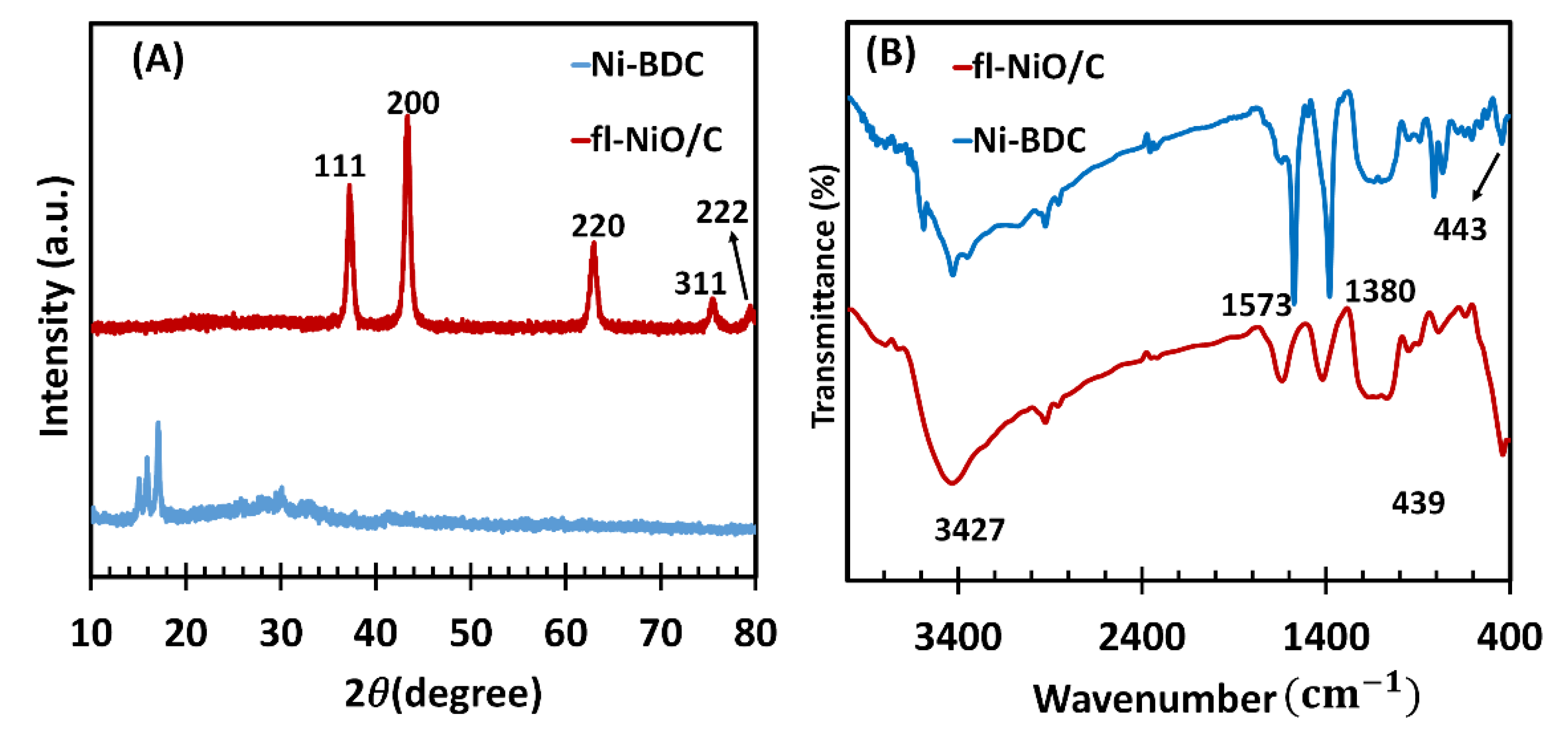
Figure 2.
(A, B, and C) FE-SEM images of Ni-BDC MOF and (D, E and F) fl-NiO/C in different magnifications.
Figure 2.
(A, B, and C) FE-SEM images of Ni-BDC MOF and (D, E and F) fl-NiO/C in different magnifications.
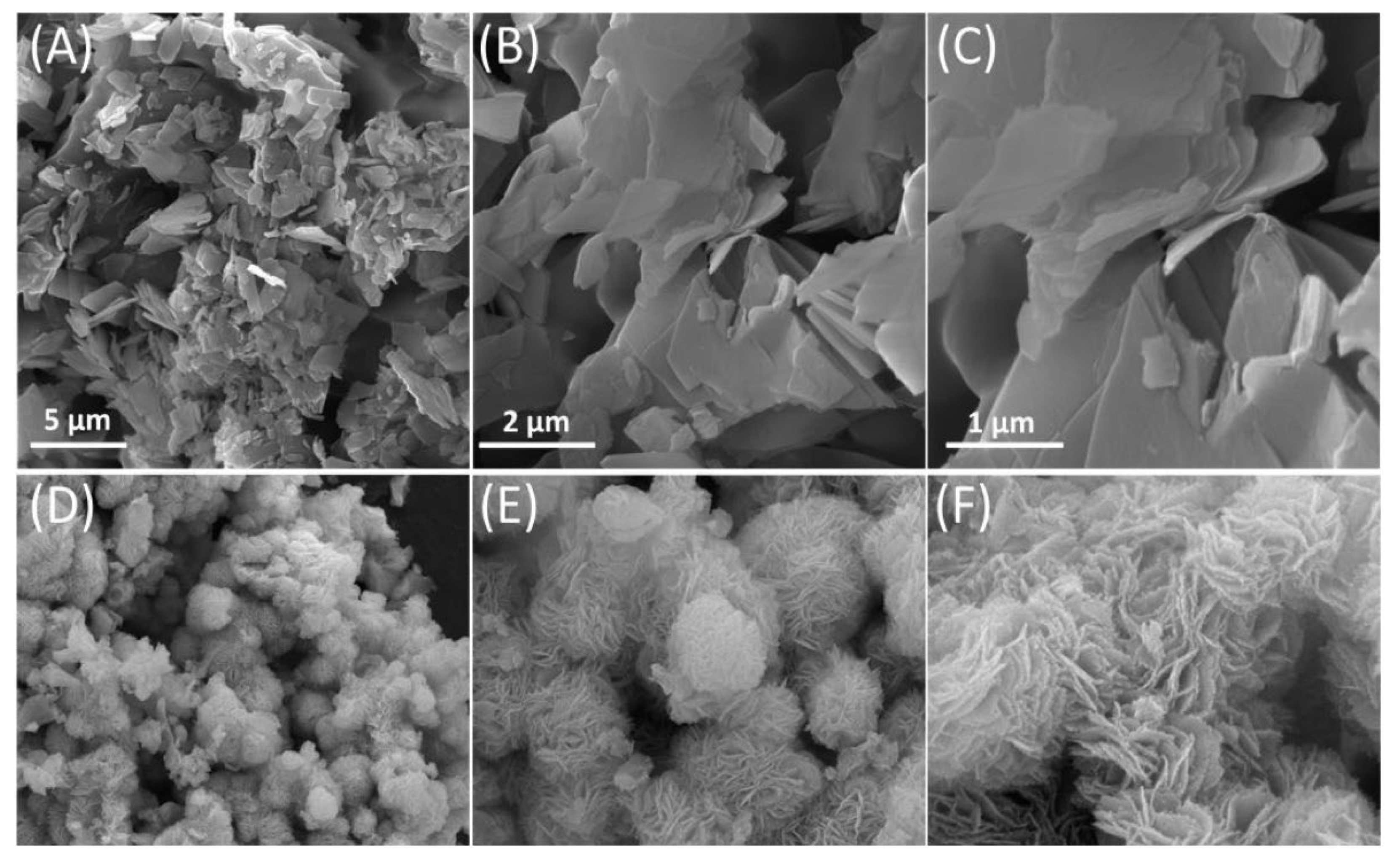
Figure 3.
EDX mapping of (A) Ni-BDC MOF and (B) fl-NiO/C.
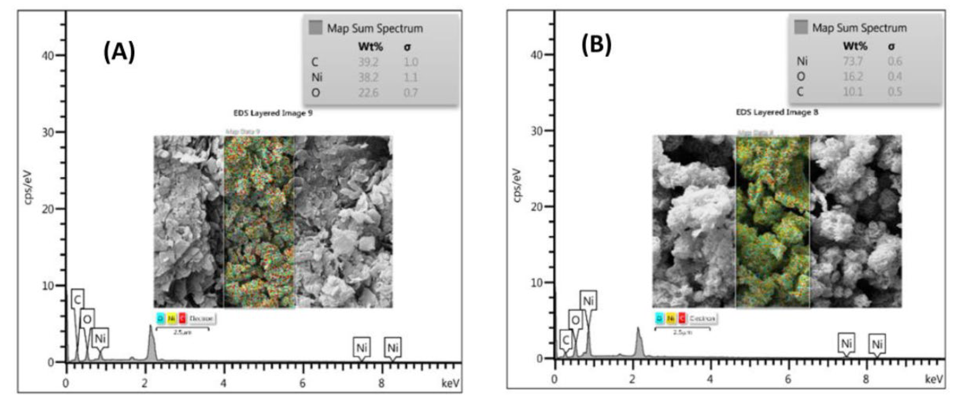
Figure 4.
(A) CVs and (B) Nyquist plots of bare GCE and fl-NiO/C/GCE in 0.1 M KCl containing 5.0 mM [Fe(CN)6] 3-/4-, (C) CVs of bare GCE and fl-NiO/C/GCE in 1 M NaOH without LGA(scan rate 50 mv/s), (D) CVs of Bare GCE and fl-NiO/C/GCE with 1mM LGA in 1 M NaOH at a scan rate of 50 mv/s.
Figure 4.
(A) CVs and (B) Nyquist plots of bare GCE and fl-NiO/C/GCE in 0.1 M KCl containing 5.0 mM [Fe(CN)6] 3-/4-, (C) CVs of bare GCE and fl-NiO/C/GCE in 1 M NaOH without LGA(scan rate 50 mv/s), (D) CVs of Bare GCE and fl-NiO/C/GCE with 1mM LGA in 1 M NaOH at a scan rate of 50 mv/s.
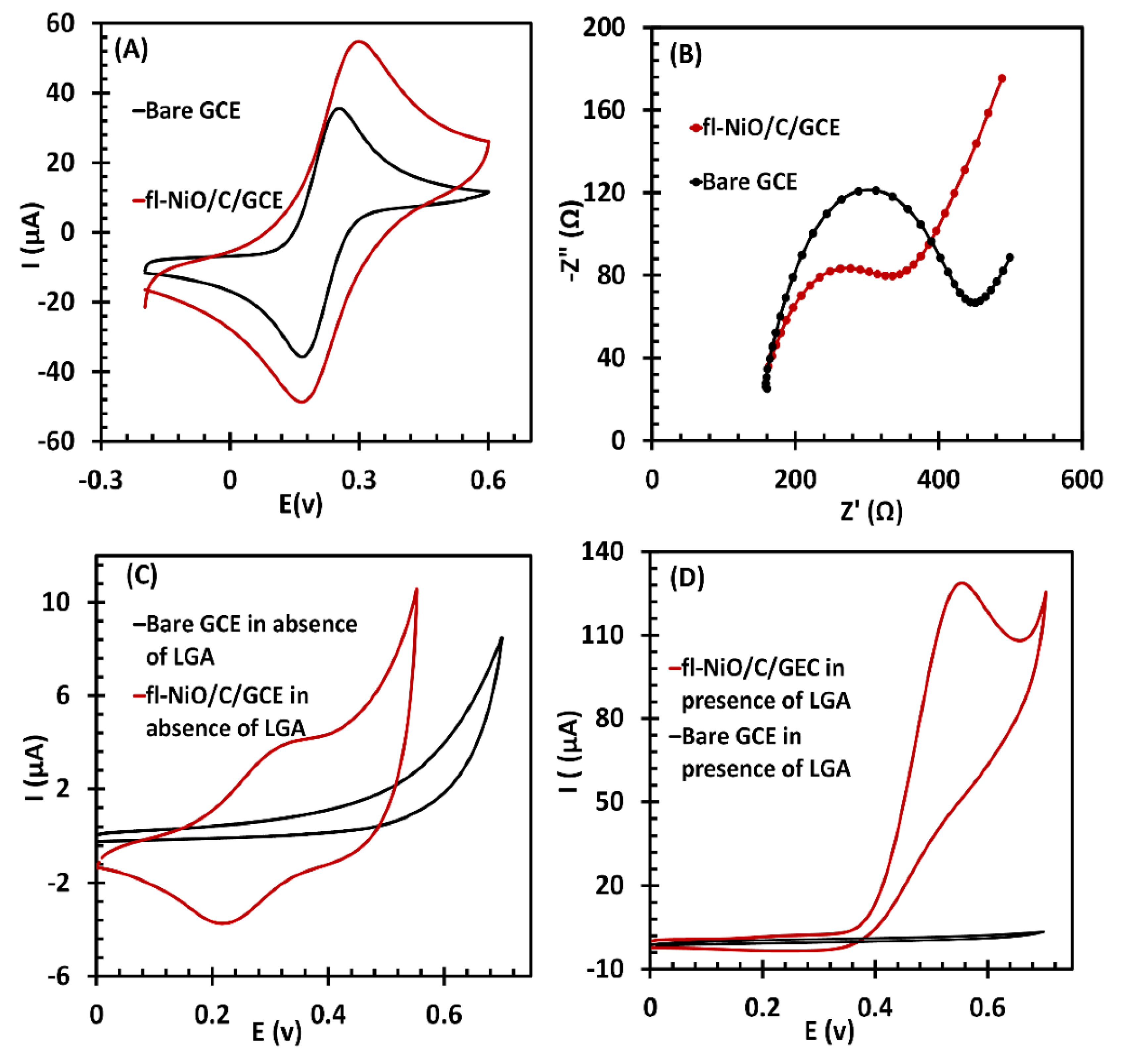
Figure 5.
(A) CVs of fl-NiO/C/GCE in 1 M NaOH containing 1mM LGA at different scan rates (10, 20, 30, 40, 50, 60 and 70 mv/s). Inset:variation of normalized current (I/υ1/2) vs. scan rate. (B) The linear relationships of I versus υ 1/2 and (C) log Ip versus log υ. (D) Plot of Ep versus log υ.
Figure 5.
(A) CVs of fl-NiO/C/GCE in 1 M NaOH containing 1mM LGA at different scan rates (10, 20, 30, 40, 50, 60 and 70 mv/s). Inset:variation of normalized current (I/υ1/2) vs. scan rate. (B) The linear relationships of I versus υ 1/2 and (C) log Ip versus log υ. (D) Plot of Ep versus log υ.
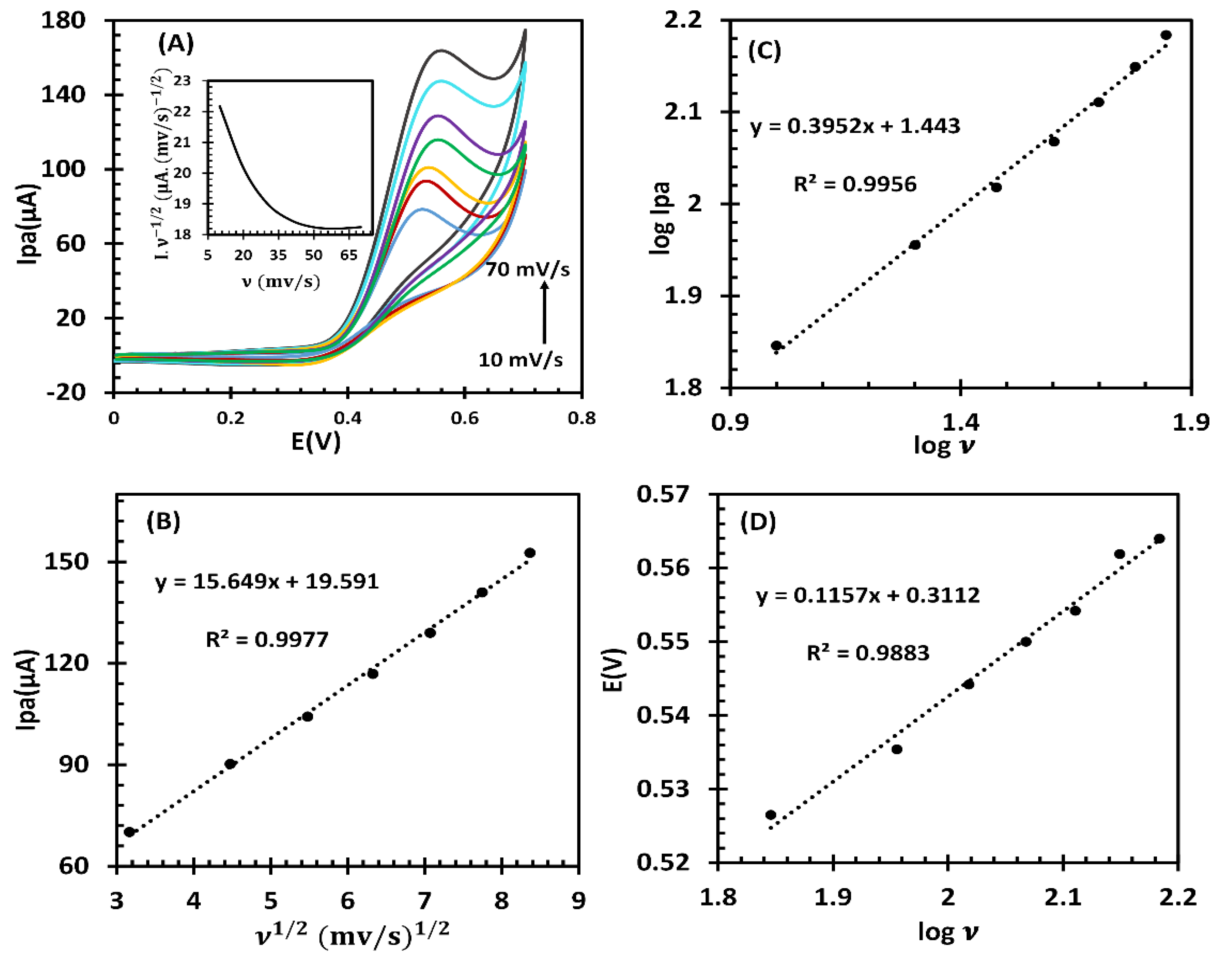
Figure 6.
(A) Chronoamperograms of fl-NiO/C/GCE in 1 M NaOH solution containing different concentrations of LGA 0, 250, 500, 300, 700, and 1000 μM (Insets: (a) plots of I vs. t−1/2 obtained from chronoamperograms, (b) plot of the slope of the straight lines from inset (a) against the LGA concentration).
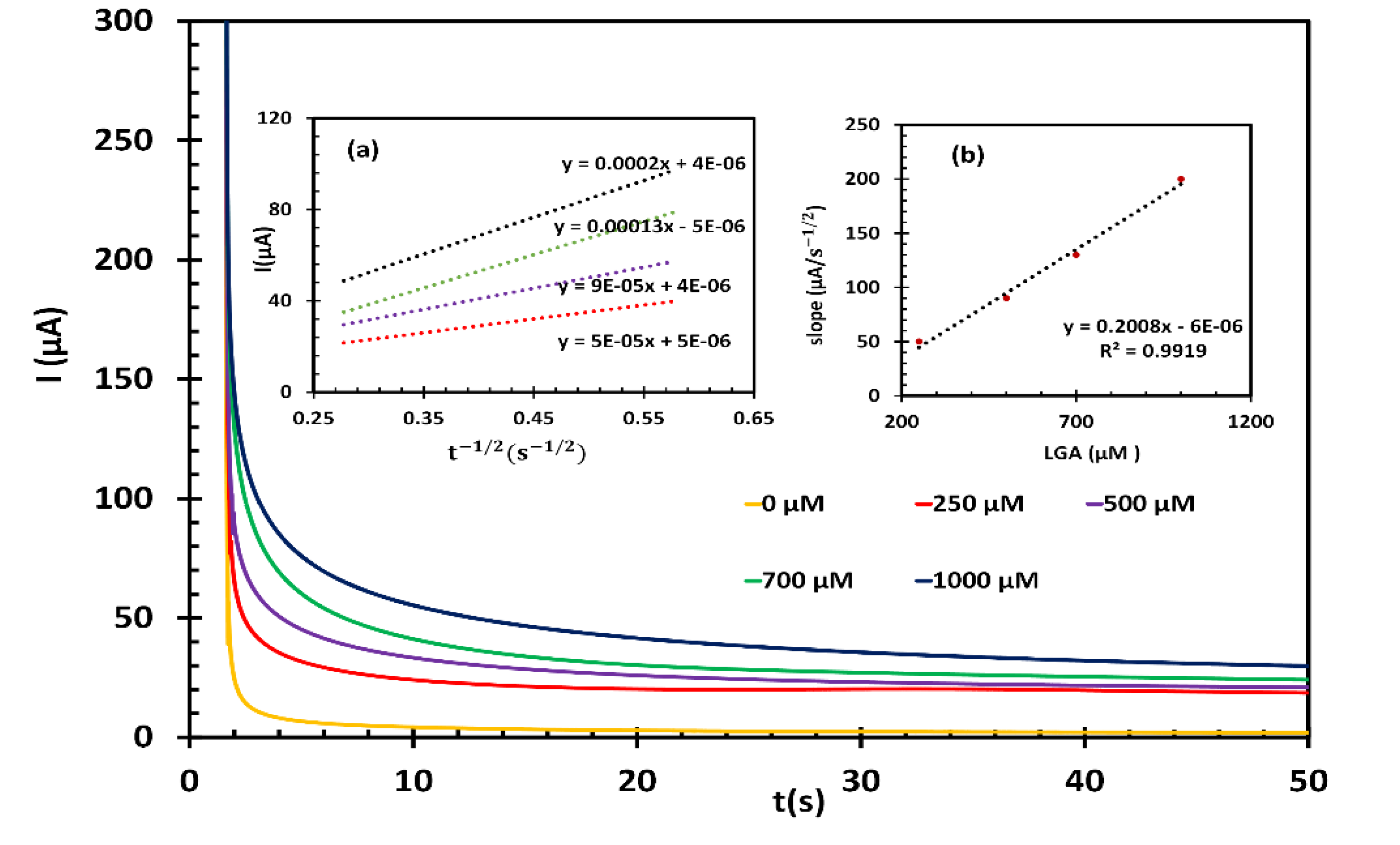
Figure 7.
(A) EIS curves of different concentrations of LGA (10.0, 20.0, 30.0, 40.0, 50.0, 60.0, 70.0, 80.0, 90.0, 100.0, 200.0, 400.0, 600.0 and 800.0 µM. inset: high magnifications of EIS curves). (B) The linear relationship between the logarithm of the LGA concentrations and Rct.
Figure 7.
(A) EIS curves of different concentrations of LGA (10.0, 20.0, 30.0, 40.0, 50.0, 60.0, 70.0, 80.0, 90.0, 100.0, 200.0, 400.0, 600.0 and 800.0 µM. inset: high magnifications of EIS curves). (B) The linear relationship between the logarithm of the LGA concentrations and Rct.
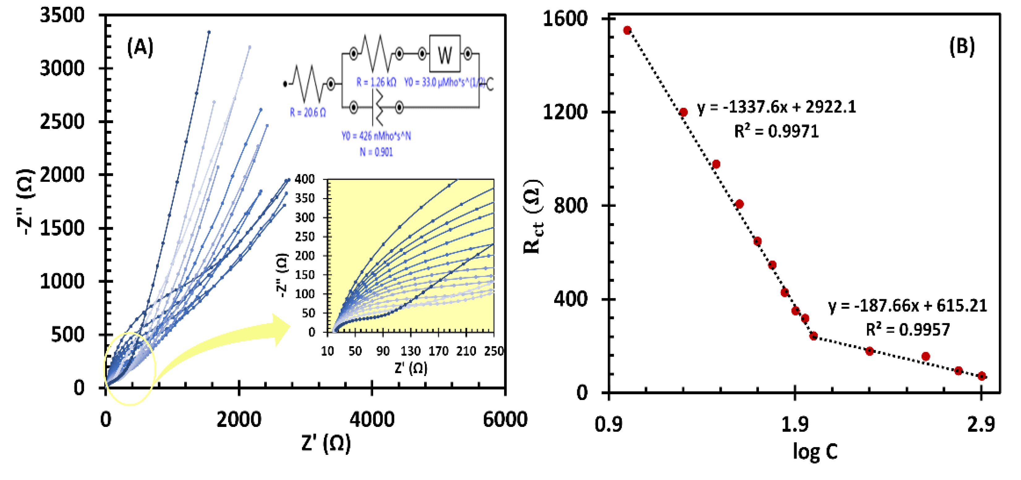
Figure 8.
Interference study of fl-NiO/C/GCE in 1 M NaOH in presence of 5 mM of Glu, 0.1 mM of AA and 0.4 mM of UA alongside 60 µM of LGA.
Figure 8.
Interference study of fl-NiO/C/GCE in 1 M NaOH in presence of 5 mM of Glu, 0.1 mM of AA and 0.4 mM of UA alongside 60 µM of LGA.
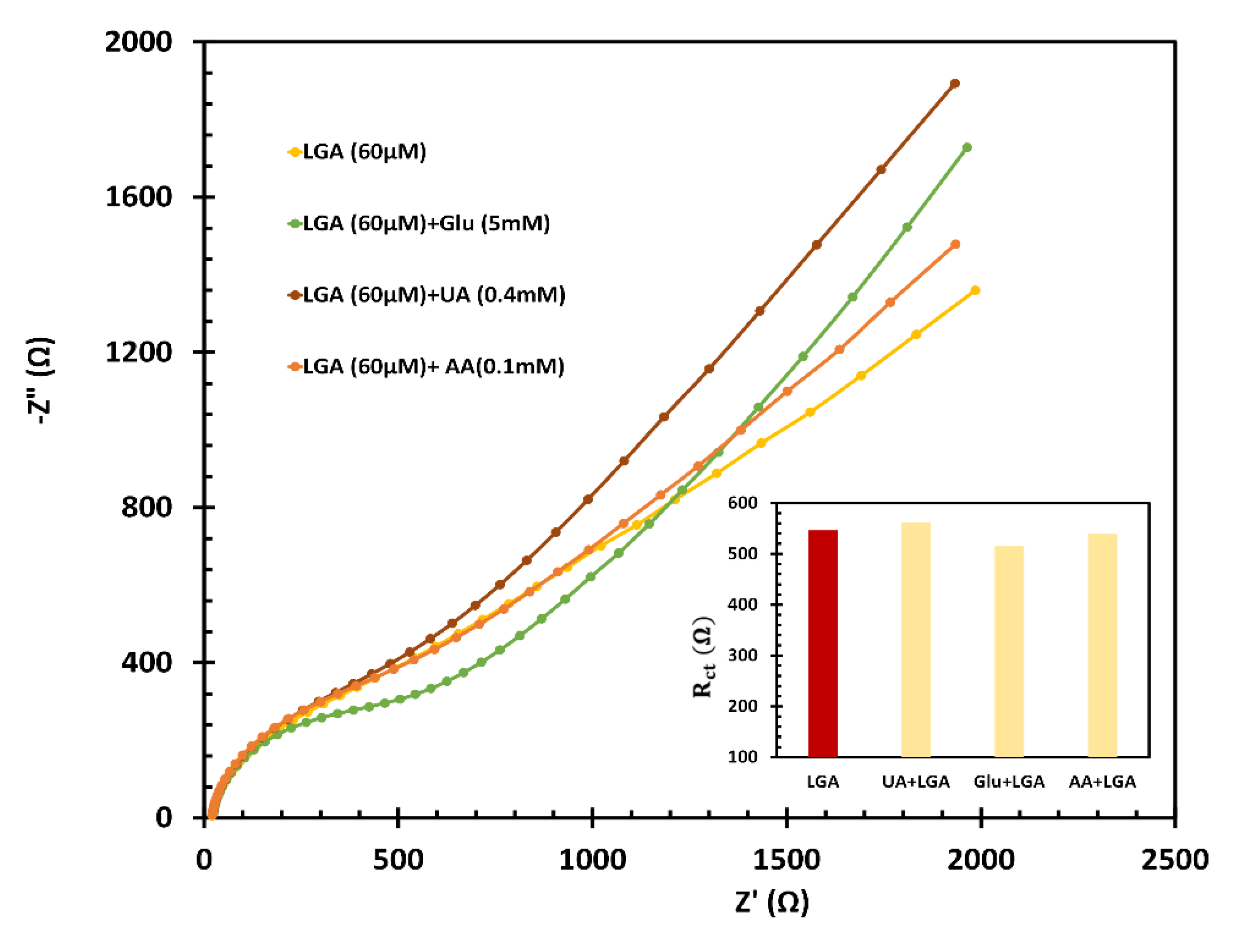

Table 1.
Comparison of different non-enzymatic sensors for L-glutamic acid detection.
| Electrodes | Detection method | Linearity range (mM) |
Sensitivity (μA mM-1 cm-2) |
LOD2 (μM) |
Enzyme | References |
|---|---|---|---|---|---|---|
|
NiNAE1 |
I-V |
0.50 – 8.00 |
65.0 |
135.00 |
no enzyme |
[23] |
|
NiO/GCE |
amperometric |
1.00 – 8.00 |
11.00 |
272.00 |
no enzyme |
[24] |
|
Au@MoS2/Chitosan/ GCE |
DPV3 |
0.05 μM – 0.20 |
--- |
0.03 |
no enzyme |
[46] |
|
PPy4/Nafion/Chitosan/ GlutOx5 |
amperometric |
0.01−0.88 |
38 |
2.5 |
GlutOx |
[45] |
|
GlutOx/cMWCNT6/AuNP/Chitosan |
CV |
0.005 − 0.5 |
155 |
1.6 |
GlutOx |
[19] |
|
GlutOx/APTES7/ ta-C/P8 |
amperometric |
0.01 – 0.5 |
2.9 |
10.0 |
GlutOx |
[21] |
|
fl-NiO/C/GCE |
EIS |
0.01 – 0.80 |
486.98 |
1.28 |
no enzyme |
This work |
1Nickel nanowire array, 2Limit of detection,3Differential Pulse Voltammetry, 4Polypyrrole, 5glutamate oxidase, 6Multi-walled carbon nanotubes, 7(3-aminopropyl)triethoxysilane, 8Tetra-hedral amorphous carbon.
Table 2.
Determination of LGA level in blood plasma sample using the fl-NiO/C/GCE electrode (in 1M NaOH solution).
Table 2.
Determination of LGA level in blood plasma sample using the fl-NiO/C/GCE electrode (in 1M NaOH solution).
| Blood plasma sample | Method | Found by This sensor (μM) | Found by HPLC (μM) | Recovery% | texperimental |
|---|---|---|---|---|---|
| I | EIS | 89.1 | 90.1 | 98.91 | 1.21 |
| II | EIS | 46.0 | 45.1 | 102.13 | 1.27 |
| III | EIS | 30.9 | 31.3 | 99.55 | 1.83 |
Disclaimer/Publisher’s Note: The statements, opinions and data contained in all publications are solely those of the individual author(s) and contributor(s) and not of MDPI and/or the editor(s). MDPI and/or the editor(s) disclaim responsibility for any injury to people or property resulting from any ideas, methods, instructions or products referred to in the content. |
© 2024 by the authors. Licensee MDPI, Basel, Switzerland. This article is an open access article distributed under the terms and conditions of the Creative Commons Attribution (CC BY) license (http://creativecommons.org/licenses/by/4.0/).
Copyright: This open access article is published under a Creative Commons CC BY 4.0 license, which permit the free download, distribution, and reuse, provided that the author and preprint are cited in any reuse.


