Submitted:
14 October 2024
Posted:
15 October 2024
You are already at the latest version
Abstract
This study investigates the phase and elemental distribution in a suspension plasma-sprayed (SPS) Li4Ti5O12 (LTO) thin-film anode for solid-state lithium batteries, deposited on an SS-304 substrate. Advanced synchrotron-based μXRD and μXRF techniques were employed for micro-scale characterization, revealing distinct phase regions influenced by thermal exposure during the SPS process. The dominant Li4Ti5O12 phase was retained across most of the film, with localized transformations to secondary phases Li2Ti3O7, Li2TiO3, and TiO2 near the substrate interface, primarily due to prolonged high-temperature exposure and subsequent lithium loss. These findings underscore the importance of controlling SPS parameters to minimize lithium loss and optimize phase stability and interfacial integrity in solid-state battery components.
Keywords:
Focused ion beam milling
; LTO thin-film ceramic solid-state battery electrode
; Suspension plasma spraying
; Synchrotron micro-X-ray diffraction and micro-X-ray fluorescence
; thin films
Introduction
Solid-state batteries (SSBs), harnessing the potential of ceramic fast ion conductors, are widely acclaimed for their exceptional attributes, including high energy density, enhanced power density, safety, a broad electrochemical stability window, absence of electrolyte leakage, and extended cycle life [1,2,3]. The diverse inorganic materials contributing to state-of-the-art SSBs encompass solid electrolytes, cathode, and anode like Li4Ti5O12 (LTO). Within the pseudo-binary LiO2–TiO2 system for LTO, Li4Ti5O12 stands out for battery applications due to its excellent cycling performance and long life in the cubic spinel structure [4,5,6,7,8].
Advanced production methods like pulsed laser deposition (PLD), chemical vapor deposition (CVD), and electrostatic spray deposition are used to fabricate high-quality thin-film battery components. While effective, these methods are complex, costly, and have slow deposition rates. In contrast, Suspension Plasma Spraying (SPS) offers a simpler, cost-effective, and industrially viable alternative for producing thin-film SSBs [9,10,11,12].
In SPS, ceramic or metallic powders suspended in a liquid medium are sprayed into a plasma plume from a plasma spray torch. The suspension stream is atomized into fine droplets due to atomization gas and further into finer droplets by viscous thermal-plasma (plasma plume temperature typically ranges from 10,000°C to 15,000°C) [3] where the liquid medium (solvent) is evaporated first, and the remnant solute particles then partially or fully melt in-flight before impacting the substrate to form a thin coating by rapid quenching in a layer-by-layer fashion. The cooling rates in plasma spraying can range from 104 to 109 Kelvin per second (K/s) [14,15]. The detailed mechanism of coating formation in SPS, involving injection of suspension into plasma, is described by Ganvir et al. [16]. Process parameters like plasma gas flow rate, suspension feed rate, spray distance, etc. are known to considerably influence coating properties [17]. SPS processing is ideal for manufacturing thin-film solid-state batteries, enabling rapid fabrication of films with tailored microstructures and controlled porosity over large areas [16]. A key challenge in using SPS for thin-film SSBs is creating solid-solid interfaces with sufficient integrity, as SPS coatings depend on mechanical anchoring for bonding. Additionally, the extreme heat from plasma can degrade and decompose LTO phases, alter their chemistry, and cause elemental interdiffusion between the ceramic anode and metallic current collector. Decomposition of the spinel phase LTO (Li4Ti5O12) to Lithium meta-titanate (Li2TiO3) and Ramsdellite (Li2Ti3O7) is a common phenomenon reported at temperatures above 1015 °C [18,19].
Therefore, characterizing the SPS-deposited LTO anode thin-film on a metallic current collector is crucial for understanding phase and elemental composition within the film and across the anode-current collector interface. Due to inherent heterogeneity, localized micro-scale characterization is needed to understand chemistry variations, especially in the narrow interface region. Traditional bulk characterization methods are unable to capture variations in structures such as phase composition and chemistry at the microscale. Microscale characterization of SSB components is particularly informative. Techniques like SPS, which inherently introduces structural heterogeneity, are especially relevant for this analysis. In this context, Synchrotron micro XRD/XRF (hereafter μXRD/μXRF) is a technique that allows for micro-scale localized characterization of material structure. The μXRD/μXRF scanning imaging is a non-destructive technique that provides information on the spatial distribution of chemical elements and crystalline phases present [20,21]. Therefore, in this work, the above techniques were explored to study the solid-solid interfacial regions in the SPS-produced thin-film SSB LTO anode deposited on the SS-304 substrate.
Experimental Works
Coating material and deposition process: Lithium Titanium Oxide powder, Li4Ti5O12 (LTO) from NEI Corporation, USA, was utilized, featuring an average particle size of 1.5-3 micrometers. A disk-shaped Stainless Steel 304 (SS-304) substrate with a diameter of 25 mm and a thickness of 2 mm was employed as a current-collector substrate. The chemical composition of the LTO powder and SS-304 substrate is shown in Table 1. Figure 1 depicts the morphology of the LTO powder particles, as observed through Scanning Electron Microscopy (SEM) conducted using an APREO field emission SEM (FE-SEM) from Thermo Fisher Scientific, U.S., equipped with an EDS detector. The SEM micrograph of the LTO thin-film cross-section is shown in Figure 1-c indicating a uniform deposition of the LTO thin film. The suspension was formulated in deionized water, comprising a 20 wt.% solid load of LTO powder and 1 wt.% of 1-Methyl-2-pyrrolidinone (NMP) from Sigma-Aldrich as an additive. Subsequently, the LTO thin-film was deposited using an Axial III high-power plasma torch (Northwest Mettech Corp., Vancouver, Canada) equipped with a Nanofeed 350 suspension feed system. The SPS process parameters are shown in Table 2. Further details about this technique and the subsequent coating formation mechanisms can be found elsewhere [10,16]. The choice of the sample in this study was guided by the authors’ earlier work [22], where processing conditions were optimized. This allowed for in-depth, advanced characterization on the selected sample, ensuring comprehensive insights under proven optimal conditions.
Sample preparation for synchrotron µXRD/μXRF: A Focused Ion Beam (FIB) was used to prepare a sample from the LTO layer for micro-characterization. This process involved a Xe+ ion beam at 30 kV for milling and 12 kV for carbon deposition, which attached the manipulator to the micro-sample for lift-out and mounting on a pin for x-ray measurements. As shown in Figure 2, the preparation includes multiple steps, resulting in a sample of 250 µm x 200 µm x 40 µm. The 40 µm thickness is determined by the x-ray beam energy and material absorption. The height ensures the sample contains all layers and some substrate material. In Figure 2-l, the yellow-dotted and red-dotted lines indicate the LTO thin-film and the SS-304 substrate, respectively.
Synchrotron µXRD and µXRF: The chemical composition and crystalline phases at the sample interface were measured using µXRF- and µXRD-contrast microscopy at the microXAS beamline, Swiss Light Source (PSI) [24] (see schematic in Figure 3). The XRD data was acquired using the Dectris Eiger 4M single photon counting detector [25] and XRF using 4 SDD detectors positioned around the sample. During a raster scan over the ceramic sample cross-sections, µXRD and µXRF measurements were simultaneously performed with detectors placed as shown in Figure 3. The X-ray beam was focused to 1 μm. A sample manipulator moved the sample in 0.5 μm steps (x and y) in the plane normal to the beam with a 200 ms acquisition time per step. For more details on the procedures, see Colldeweih et al. [26]. The X-ray beam wavelength was 0.6812 Å. Detection and characterization covered a 250µm x 200µm area with 1µm x 1µm pixels and 0.5µm steps. Azimuthal integration of diffraction rings used the pyFAI Python library [27]. Each integrated diffraction pattern was assigned to a pixel in the scanned area, resulting in 3000 images showing XRD intensities at specific diffraction angles. For the same area, X-ray fluorescence spectra from each pixel were recorded and analyzed using PyMca software [28] which allowed to obtain distinct images representing spatial distribution of individual elements. Both μXRD and μXRF measurements provide complementary information and an understanding of sample structure and composition.
ImageJ (Fiji) software (ver. 1.53q) was used to evaluate diffraction patterns from selected regions. X’Pert High Score plus software (ver. 4.9) and Topas 6 (Bruker) was used to analyze the obtained XRD patterns. The crystalline phases were identified based on Rietveld refinement.
Results and Discussion
Based on synchrotron µXRF results, the energy range of the XRF spectra at the microXAS beamline enabled imaging of the sample’s chemical composition, particularly for elements with emission lines above 2 keV. Figure 5 shows the elemental distribution in the FIB-milled samples from µXRF. In Figure 4-a, the bright distribution of Ti indicates a stable LTO thin-film on the substrate with a sharp interface, supporting μXRD findings that confirm the retention of the original Li4Ti5O12 phase. Figure 4-b to Figure 4-e illustrate the elemental distributions of Fe, Cr, Ni, and Mn from the 304-stainless steel substrate, showing interdiffusion into the deposited layer. This interdiffusion within the first few microns aligns with μXRD results, which detected secondary phases like Li2Ti3O7, Li2TiO3, and TiO2, likely formed by the altered stoichiometry and oxidation states of Ti due to the presence of Fe, Cr, Ni, and Mn.
More importantly, based on synchrotron µXRD results, μXRD analysis revealed important details about phase stability and transformations in the plasma-sprayed LTO thin film. Figure 5-a to Figure 5-d show cross-sectional μXRD patterns from different regions of the film, analyzed to understand phase distribution. The examined regions include: (a) LTO1, far from the interface; (b) LTO2, near the interface; (c) the LTO/substrate interface; and (d) the SS-304 substrate. The μXRD results confirm the persistence of the Li4Ti5O12 (LTO) phase throughout the film, indicating its stability despite the high thermal fluxes of the SPS process. Figure 5-e and Figure 5-f show diffraction beam intensities at angles of 11.1º and 19.3º, corresponding to the Li2TiO3 and bcc steel phases, respectively, illustrating their spatial distribution. Despite the dominant presence of Li4Ti5O12, the detection of secondary phases— Li2Ti3O7, Li2TiO3 and TiO2—highlights the complex thermodynamic and kinetic processes at play during film deposition. As can be seen from the phase diagram in Figure 5-g (red dotted line), Li4Ti5O12 is an intermediate phase that can be solid-state transformed to Li2Ti3O7, Li2TiO3, and TiO2 and vice versa. The presence of Li2Ti3O7 and Li2TiO3, even in regions far from the interface, suggests that partial lithium deintercalation and phase transformation occur under the extreme conditions of plasma spraying. This transformation is likely driven by the elevated temperatures, which promote the oxidation of Ti³⁺ to Ti⁴⁺ and result in phases with different Li/Ti ratios, such as Li2Ti3O7 (Li/Ti = 0.67) and Li2TiO3 (Li/Ti = 2.0), compared to the original Li4Ti5O12 (Li/Ti = 0.8). The formation of TiO₂, confined to the LTO2 region, may be attributed to localized oxidation processes where Ti³⁺ is fully oxidized to Ti⁴⁺, exacerbated by oxygen ingress during deposition [8,29,30]. Although Li4Ti5O12 is the desired phase for high-performance anode, Li2Ti3O7 and Li2TiO3 phases are also shown to have good specific capacity, excellent reversibility, and cycle stability [31,32].
The variation in cooling rates across the thin-film and substrate interface plays a crucial role in determining the final phase composition. In the LTO1 region (Figure 5-a), the μXRD pattern reveals the presence of crystalline Li4Ti5O12 and Li2Ti3O7, indicating that high-temperature conditions promote the loss of lithium and subsequent formation of lower Li/Ti ratio phases. However, the bulk film’s resistance to extensive lithium loss suggests that kinetic barriers or rapid quenching may prevent widespread degradation, preserving the Li4Ti5O12 phase even in thermodynamically favorable conditions for transformation.
The detection of Li2TiO3 in the LTO2 (Figure 5-b) and interface regions further supports the notion of temperature-driven phase evolution, with sufficient thermal energy available to induce solid-state transformations. Given the low thermal conductivity of LTO (1.23 W.m⁻¹.K⁻¹) [33], the sustained heat within the thin-film during deposition likely facilitates these transformations, allowing initially deposited Li4Ti5O12 to partially convert to Li2Ti3O7 and Li2TiO3. The observed TiO2 formation, though limited, suggests that localized oxidation processes may occur, particularly in regions where thermal gradients and oxygen availability converge, leading to the complete Li loss and oxidation of Ti³⁺ to Ti⁴⁺ [8].
At the interface between the LTO film and the SS-304 substrate (Figure 5-c), the μXRD pattern detected significant peaks corresponding to Li4Ti5O12. The high cooling rates experienced by the first few layers of molten Li4Ti5O12 in contact with the highly conductive SS-304 substrate (thermal conductivity of 14.6 W.m⁻¹.K⁻¹ [34]) appear to inhibit phase transformation, preserving the original LTO structure. However, the presence of minor peaks corresponding to Li2Ti3O7 and Li2TiO3 suggests that small regions of the film may still undergo phase changes due to localized compositional inhomogeneities or slower cooling rates.
The presence of both FCC and BCC steel phases in the interface region suggests that the substrate may undergo phase transformations during SPS, likely due to interdiffusion and high thermal gradients. [35]. XRD mapping of crystalline phases showed a significantly higher concentration of the BCC phase near the interface compared to the substrate bulk. This is illustrated in Figure 5-f, where the color scale indicates the BCC phase. The increased BCC phase is due to the diffusion of atoms that stabilize the FCC phase through the interface [36,37]. Elemental interdiffusion from the substrate to the LTO film may particularly be occurring, as Fe, Cr, Ni, and Mn—all present in SS-304—can migrate into the LTO layer. This diffusion can alter the local stoichiometry and phase stability within the LTO, potentially influencing the oxidation state of Ti and the formation of solid solution or secondary phases. For instance, the ionic radii of Fe³⁺ (0.65 Å), Cr³⁺ (0.62 Å), Ni²⁺ (0.69 Å), and Mn³⁺ (0.645 Å) are comparable to those of Ti⁴⁺ (0.61 Å) and Ti³⁺ (0.67 Å), making them potential candidates for substitution into the LTO lattice, thus forming solid solutions. These substitutions could introduce lattice strain, modify the phase stability, and influence the electrochemical properties of the LTO film. Additionally, the presence of Ni and Cr, known for their catalytic properties, could facilitate the oxidation of Ti³⁺ to Ti⁴⁺ [38,39].
The µXRD and µXRF analyses not only reveal the complexity of the interfacial region between the LTO material and substrate, showing mixed phases and solid solutions due to elemental interdiffusion, but also reveal the complex interfacial region between the LTO material and substrate, highlighting mixed phases and solid solutions caused by elemental interdiffusion. This critical interfacial zone, characterized by overlapping distributions of Ti, Fe, Cr, Ni, and Mn, underscores the significant impact of these elements on the LTO anode’s structural integrity and electrochemical properties. The µXRF results, which map the spatially resolved chemical composition, confirm the crucial role of substrate element interdiffusion in forming complex interfacial structures. This interplay between chemical composition and phase transformation emphasizes the need to control interfacial reactions to optimize the performance and stability of LTO-based anodes in lithium-ion batteries.
Conclusion
This study used advanced synchrotron-based µXRD and µXRF techniques to analyze phase and elemental distribution in an LTO thin-film anode, produced via suspension plasma spray (SPS) for solid-state lithium batteries. The LTO film was deposited on an SS-304 substrate, and micro-scale analysis provided insights into phase stability and interfacial interactions.
The μXRD analysis confirmed the persistence of the Li4Ti5O12 phase across the film, with distinct regions (LTO1 and LTO2) exhibiting different phase compositions due to variations in thermal exposure during SPS. In LTO1, Li4Ti5O12 was predominant with minor Li2Ti3O7 formation due to lithium loss at high temperatures. Near the SS-304 substrate, rapid cooling rates preserved the Li4Ti5O12 phase, while in the LTO2 region, prolonged high-temperature exposure led to the formation of additional phases like Li2TiO3. The µXRF together with μXRD analysis revealed elemental interdiffusion of Fe, Cr, Ni, and Mn from the SS-304 substrate into the LTO layer, resulting in increased amount of the BCC phase in steel, contributing to localized phase transformations and the formation of complex structures at the interface. The interplay between the thermal history, cooling rates, and substrate interactions was found to govern the distribution and stability of phases within the thin film.
Overall, this study demonstrates the intricate relationship between processing conditions and material properties in SPS-deposited LTO thin films. The findings highlight the need to control SPS parameters to enhance the performance and stability of solid-state lithium battery components, especially at the anode-substrate interface.
Funding
This research was supported by the GREEN-BAT project [2022–2025] under the M-ERA.Net framework. The authors gratefully acknowledge the support of the Research Council of Finland and M-ERA.NET 3 from the European Commission, as well as the respective national and regional financiers from Germany and Sweden. The Swedish portion of this research, conducted at University West, Sweden, was funded by the following projects: (a) the proof-of-concept project NovelCABs, supported by the Swedish Energy Agency (Energimyndigheten, Dnr 2021-002227), and (b) the transnational M-ERA.NET 3 project Green-BAT, with backing from the European Commission, with Vinnova (the Swedish Governmental Agency for Innovation Systems) as the national financier for Swedish participation. The Authors also acknowledge Swiss Light Source (SLS) for granting the beamtime at the microXAS beamline.
Acknowledgment
The authors would like to acknowledge the invaluable contributions of Stefan Björklund and Killian Clovis from University West, Trollhättan, Sweden, for their assistance with plasma spraying of the battery materials and electron microscopy for characterizing the sprayed layer.
References
- P. Kurzweil, “Gaston Planté and his invention of the lead–acid battery—The genesis of the first practical rechargeable battery,” J Power Sources, vol. 195, no. 14, pp. 4424–4434, Jul. 2010. [CrossRef]
- D. A. J. Rand and P. T. Moseley, “Energy Storage with Lead–Acid Batteries,” in Electrochemical Energy Storage for Renewable Sources and Grid Balancing, Elsevier, 2015, pp. 201–222. [CrossRef]
- J. Garche, C. Dyer, P. T. Moseley, Z. Ogumi, D. A. J. Rand, and B. Scrosati, Encyclopedia of electrochemical power sources. Newnes, 2013.
- A. B. Yaroslavtsev, I. A. Stenina, T. L. Kulova, A. M. Skundin, and A. V. Desyatov, “Nanomaterials for Electrical Energy Storage,” in Comprehensive Nanoscience and Nanotechnology, Elsevier, 2019, pp. 165–206. [CrossRef]
- M. R. Mohammadi and D. J. Fray, “Low temperature nanostructured lithium titanates: controlling the phase composition, crystal structure and surface area,” J Solgel Sci Technol, vol. 55, no. 1, pp. 19–35, Jul. 2010. [CrossRef]
- M. Vijayakumar, Sebastien Kerisit, Kevin M. Rosso, Sarah D. Burton, Jesse A. Sears, Zhenguo Yang, Gordon L. Graff, Jun Liu, Jianzhi Hu, “Lithium diffusion in Li4Ti5O12 at high temperatures,” J Power Sources, vol. 196, no. 4, pp. 2211–2220, Feb. 2011. [CrossRef]
- E. M. Sorensen, S. J. Barry, H.-K. Jung, J. M. Rondinelli, J. T. Vaughey, and K. R. Poeppelmeier, “Three-Dimensionally Ordered Macroporous Li 4 Ti 5 O 12 : Effect of Wall Structure on Electrochemical Properties,” Chemistry of Materials, vol. 18, no. 2, pp. 482–489, Jan. 2006. [CrossRef]
- X. Sun, P. V. Radovanovic, and B. Cui, “Advances in spinel Li 4 Ti 5 O 12 anode materials for lithium-ion batteries,” New Journal of Chemistry, vol. 39, no. 1, pp. 38–63, 2015. [CrossRef]
- S. Zhou, N. Huang, J. Yan, H. Zhang, and X. Li, “High Rate Performance Li 4 Ti 5 O 12 /N-doped Carbon/Stainless Steel Mesh Flexible Electrodes Prepared by Electrostatic Spray Deposition for Lithium-ion Capacitors,” Chem Lett, vol. 49, no. 3, pp. 337–340, Mar. 2020. [CrossRef]
- Arman Hasani, Mathis Luya, Nikhil Kamboj, Chinmayee Nayak, Shrikant Joshi, Antti Salminen, Sneha Goel, Ashish Ganvir, “Laser Processing of Liquid Feedstock Plasma-Sprayed Lithium Titanium Oxide Solid-State-Battery Electrode,” Coatings, vol. 14, no. 2, p. 224, Feb. 2024. [CrossRef]
- X. Liang, Y. Wang, X. Zhang, D. Han, L. Lan, and Y. Zhang, “Performance study of a Li4Ti5O12 electrode for lithium batteries prepared by atmospheric plasma spraying,” Ceram Int, vol. 45, no. 17, pp. 23750–23755, Dec. 2019. [CrossRef]
- X. Wu, X. Liang, X. Zhang, L. Lan, S. Li, and Q. Gai, “Structural evolution of plasma sprayed amorphous Li4Ti5O12 electrode and ceramic/polymer composite electrolyte during electrochemical cycle of quasi-solid-state lithium battery,” Journal of Advanced Ceramics, vol. 10, no. 2, pp. 347–354, Apr. 2021. [CrossRef]
- M. Oksa, E. Turunen, T. Suhonen, T. Varis, and S.-P. Hannula, “Optimization and Characterization of High Velocity Oxy-fuel Sprayed Coatings: Techniques, Materials, and Applications,” Coatings, vol. 1, no. 1, pp. 17–52, Sep. 2011. [CrossRef]
- L. Bianchi, A. C. Leger, M. Vardelle, A. Vardelle, and P. Fauchais, “Splat formation and cooling of plasma-sprayed zirconia,” Thin Solid Films, vol. 305, no. 1–2, pp. 35–47, Aug. 1997. [CrossRef]
- P. Kotalík and K. Voleník, “Cooling rates of plasma-sprayed metallic particles in liquid and gaseous nitrogen,” J Phys D Appl Phys, vol. 34, no. 4, pp. 567–573, Feb. 2001. [CrossRef]
- A. Ganvir, R. F. Calinas, N. Markocsan, N. Curry, and S. Joshi, “Experimental visualization of microstructure evolution during suspension plasma spraying of thermal barrier coatings,” J Eur Ceram Soc, vol. 39, no. 2–3, pp. 470–481, Feb. 2019. [CrossRef]
- M. Aghasibeig, F. Tarasi, R. S. Lima, A. Dolatabadi, and C. Moreau, “A Review on Suspension Thermal Spray Patented Technology Evolution,” Journal of Thermal Spray Technology, vol. 28, no. 7, pp. 1579–1605, Oct. 2019. [CrossRef]
- C. Torre-Gamarra, M. Sotomayor, W. Bucheli, J. Amarilla, J. Sanchez, B. Levenfeld, A. Varez, “Tape casting manufacturing of thick Li4Ti5O12 ceramic electrodes with high areal capacity for lithium-ion batteries,” J Eur Ceram Soc, vol. 41, no. 1, pp. 1025–1032, Jan. 2021. [CrossRef]
- G. Izquierdo and A. R. West, “Phase equilibria in the system Li2O-TiO2,” Mater Res Bull, vol. 15, no. 11, pp. 1655–1660, Nov. 1980. [CrossRef]
- P. Kaskes, T. Déhais, S. J. de Graaff, S. Goderis, and P. Claeys, “Micro–X-ray fluorescence (µXRF) analysis of proximal impactites: High-resolution element mapping, digital image analysis, and quantifications,” in Large Meteorite Impacts and Planetary Evolution VI, Geological Society of America, 2021, pp. 171–206. [CrossRef]
- H. A. O. Wang, D. Grolimund, L. R. Van Loon, K. Barmettler, C. N. Borca, B. Aeschlimann, D. Günther, “Quantitative Chemical Imaging of Element Diffusion into Heterogeneous Media Using Laser Ablation Inductively Coupled Plasma Mass Spectrometry, Synchrotron Micro-X-ray Fluorescence, and Extended X-ray Absorption Fine Structure Spectroscopy,” Anal Chem, vol. 83, no. 16, pp. 6259–6266, Aug. 2011. [CrossRef]
- S. Mathiyalagan, S. Björklund, S. Johansson Storm, G. Salian, R. Le Ruyet, R. Younesi, S. Joshi, “Facile one-step fabrication of Li4Ti5O12 coatings by suspension plasma spraying”, Materials Research Bulletin, vol. 181, Jan. 2025. [CrossRef]
- Killian Clovis, “Deposition and characteristics of ther-mal sprayed layers as solid-state thin film battery components,” University West, Trollhättan, SWEDEN, 2023.
- C. N. Borca, D. Grolimund, M. Willimann, B. Meyer, K. Jefimovs, J. Vila-Comamala, C. David, “The microXAS beamline at the swiss light source: Towards nano-scale imaging,” J Phys Conf Ser, vol. 186, p. 012003, Sep. 2009. [CrossRef]
- S. Grimm, “https://www.dectris.com/en/detectors/x-ray-detectors/eiger2/eiger2-for-synchrotrons/.”.
- A. W. Colldeweih, M. G. Makowska, O. Tabai, D. F. Sanchez, and J. Bertsch, “Zirconium hydride phase mapping in Zircaloy-2 cladding after delayed hydride cracking,” Materialia (Oxf), vol. 27, p. 101689, Mar. 2023. [CrossRef]
- G. Ashiotis, A. Deschildre, Z. Nawaz, J. P. Wright, D. Karkoulis, F. Emmanuel Piccac, J. Kieffer, “The fast azimuthal integration Python library: pyFAI,” J Appl Crystallogr, vol. 48, no. 2, pp. 510–519, Apr. 2015. [CrossRef]
- V. A. Solé, E. Papillon, M. Cotte, Ph. Walter, and J. Susini, “A multiplatform code for the analysis of energy-dispersive X-ray fluorescence spectra,” Spectrochim Acta Part B At Spectrosc, vol. 62, no. 1, pp. 63–68, Jan. 2007. [CrossRef]
- Z. Liu, Y. Huang, X. Wang, Y. Zhang, J. Ding, Y. Guo, X. Tang, “Synthesis of defects and TiO2 co-enhanced Li4Ti5O12 by a simple solid-state method as advanced anode for lithium-ion batteries,” Journal of Materials Science: Materials in Electronics, vol. 32, no. 5, pp. 6682–6687, Mar. 2021. [CrossRef]
- A. Subhan, F. Oemry, S. N. Khusna, and E. Hastuti, “Effects of activated carbon treatment on Li4Ti5O12 anode material synthesis for lithium-ion batteries,” Ionics (Kiel), vol. 25, no. 3, pp. 1025–1034, Mar. 2019. [CrossRef]
- Q. Meng, L. Wang, F. Chen, Q. Hao, and X. Sun, “Preparation of Ramsdellite-type Li2Ti3O7 hollow microspheres with high tap density by flame melting method as anode of Li-ion battery,” Mater Res Bull, vol. 161, p. 112166, May 2023. [CrossRef]
- Y. Kang, Y. Xie, F. Su, K. Dai, M. Shui, and J. Shu, “α-Li 2 TiO 3 : a new ultrastable anode material for lithium-ion batteries,” Dalton Transactions, vol. 51, no. 47, pp. 18277–18283, 2022. [CrossRef]
- K. Yang, Z. Shan, X. Liu, L. Tan, and S. Wang, “Study on Thermal Simulation of LiNi 0.5 Mn 1.5 O 4 /Li 4 Ti 5 O 12 Battery,” Energy Technology, vol. 9, no. 5, May 2021. [CrossRef]
- S. C. Chen, C. C. Wan, and Y. Y. Wang, “Thermal analysis of lithium-ion batteries,” J Power Sources, vol. 140, no. 1, pp. 111–124, Jan. 2005. [CrossRef]
- J. Pelleg, “Interdiffusion,” 2016, pp. 69–74. [CrossRef]
- G. N. Irving, J. Stringer, and D. P. Whittle, “Effect of the possible fcc stabilizers Mn, Fe, and Ni on the high-temperature oxidation of Co-Cr alloys,” Oxidation of Metals, vol. 8, no. 6, pp. 393–407, Dec. 1974. [CrossRef]
- I. Shuro, S. Kobayashi, T. Nakamura, and K. Tsuzaki, “Determination of α/γ phase boundaries in the Fe–Cr–Ni–Mn quaternary system with a diffusion-multiple method,” J Alloys Compd, vol. 588, pp. 284–289, Mar. 2014. [CrossRef]
- R. D. Shannon, “Revised effective ionic radii and systematic studies of interatomic distances in halides and chalcogenides,” Acta Crystallographica Section A, vol. 32, no. 5, pp. 751–767, Sep. 1976. [CrossRef]
- M. Mojahed, A. Gholizadeh, and H. R. Dizaji, “Influence of Ti4+ substitution on the structural, magnetic, and dielectric properties of Ni-Cu–Zn ferrite,” Journal of Materials Science: Materials in Electronics, vol. 35, no. 18, p. 1239, Jun. 2024. [CrossRef]
Figure 1.
SEM micrographs with a) low and b) high magnifications of morphology of the LTO powder, c) Cross-sectional BSE image of LTO thin-film on substrate [23].
Figure 1.
SEM micrographs with a) low and b) high magnifications of morphology of the LTO powder, c) Cross-sectional BSE image of LTO thin-film on substrate [23].
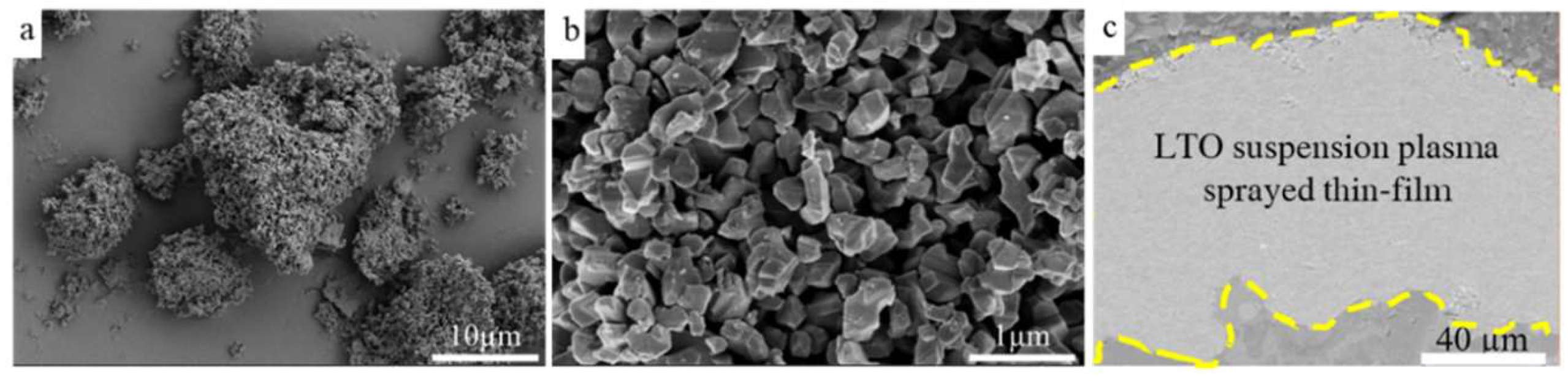
Figure 2.
FIB milling process steps: (a) Locating a region and placing of milling patterns, (b) Top-down milled micro-sample, (c) Undercut to create a free-standing micro-sample, (d) Bridge holding the micro-sample in place, (e) Attaching the micromanipulator to the micro-sample by carbon deposition, (f) Removing the bridge, (g) Fully-released sample to be lifted out, (h) Tip of the pin as is, (i) FIB milling to create a suitable mounting site at the tip of the pin, (j) Mounting the micro-sample to the pin by carbon deposition, (k) Removing the manipulator, (l) Final FIB milled micro-sample ready for the synchrotron micro-characterization.
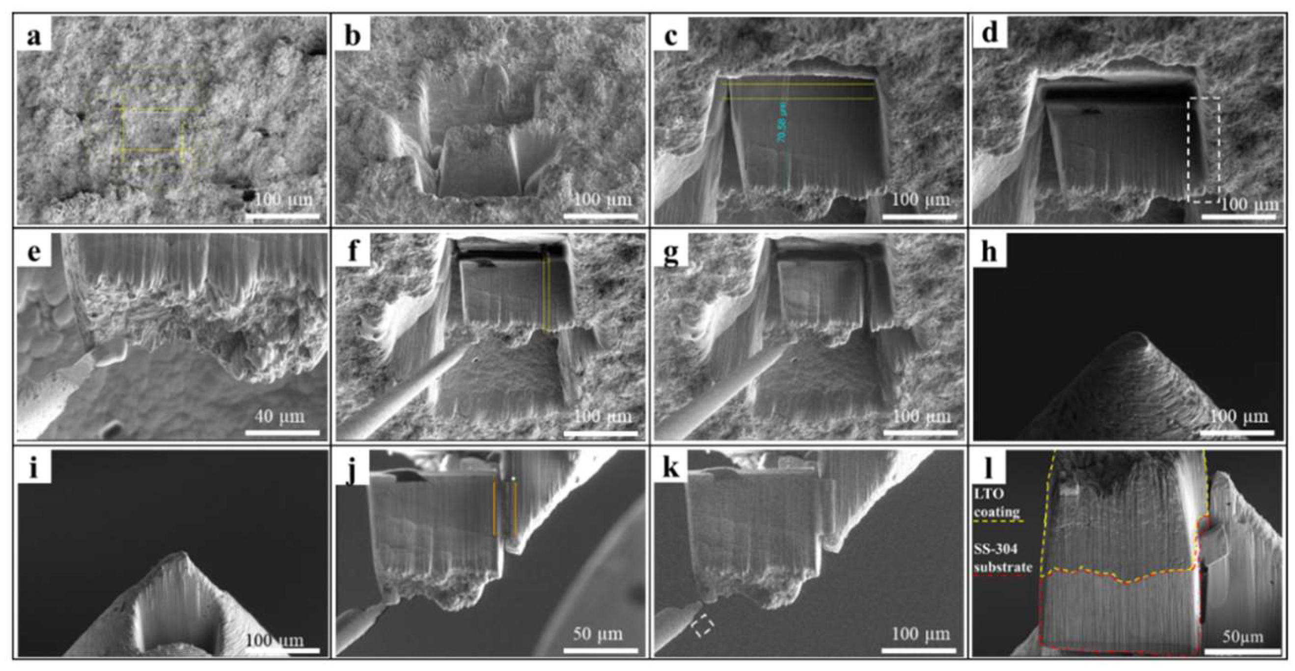
Figure 3.
Schematic illustration of the synchrotron µXRD and µXRF measurements.
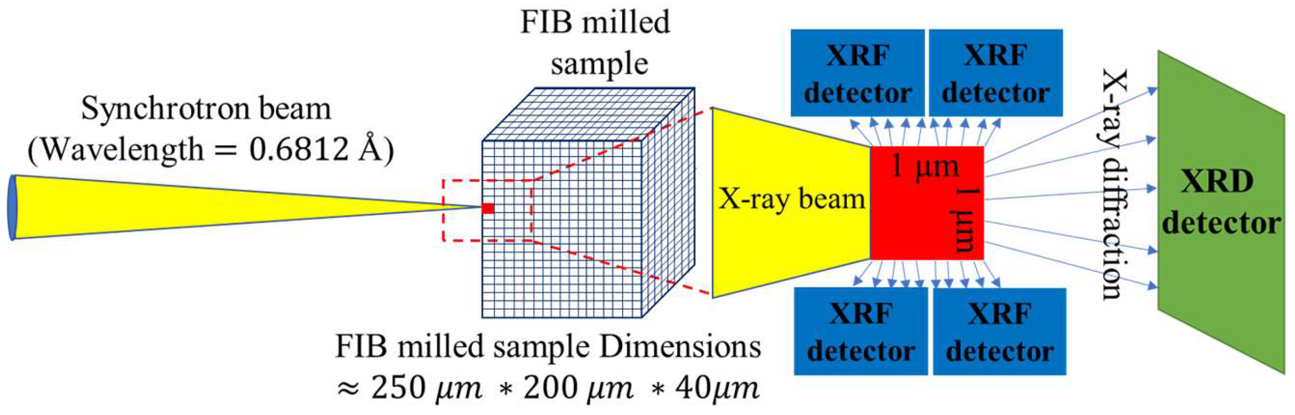
Figure 4.
elemental distribution of sample.
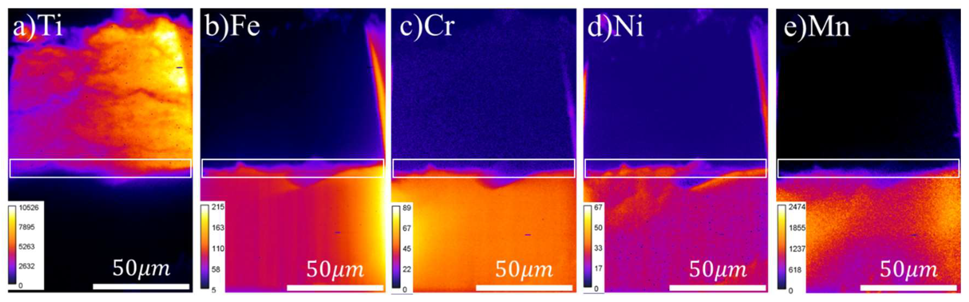
Figure 5.
XRD patterns integrated over four distinct regions: (a) LTO1, located far from the interface; (b) LTO2, positioned near the interface; (c) the interface between the LTO thin film and the substrate; and (d) the SS-304 substrate, encompassing the entire 2θ range. Two specific diffraction angles 2θ corresponding to diffraction peaks of Li2TiO3 and BCC steel are highlighted with dotted lines, and their corresponding images, are displayed in (e) at 2θ = 11.1º and (f) at 2θ = 19.3º, with all four regions indicated by color-coded dotted rectangles and a normalized scale bar showing values from 0-1. (g) The pseudo-binary Li2O–TiO2 phase diagram, adapted from [14].
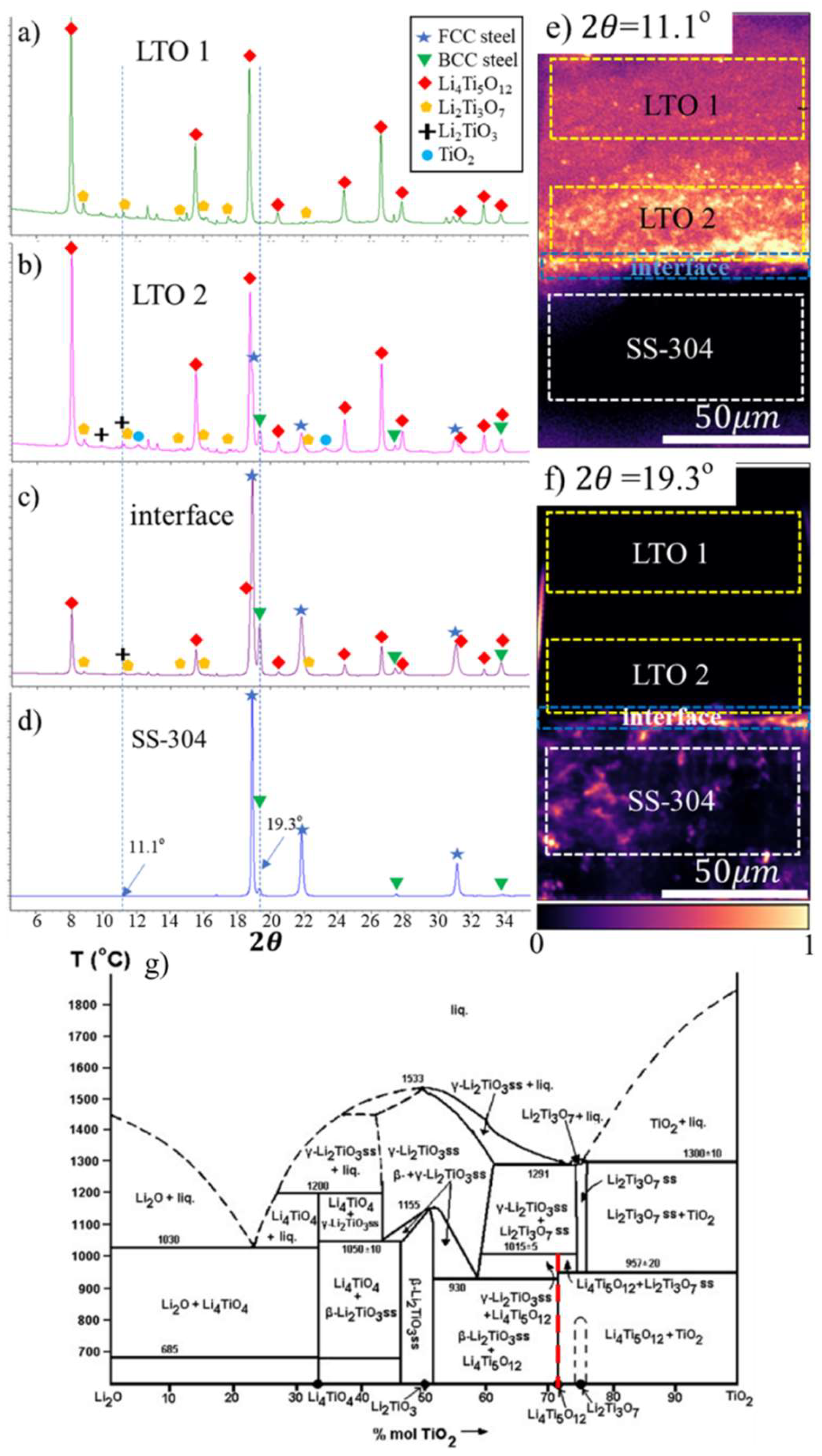

Table 1.
Chemical composition of LTO thin-film and SS-304 substrate.
| Element | Ti | O | Cl, Si, Al | Fe | Cr | Ni | Mn | C, P, S, Si, N |
|---|---|---|---|---|---|---|---|---|
| LTO powder (wt%) (Excluding Li, which could not be detected) |
54.4 | 45.2 | 0.4 | - | - | - | - | - |
| SS-304 substrate(wt%) | - | - | - | balance | 18-20 | 8-11 | 2 | 1.005 |
Table 2.
Plasma spray parameters utilized for the deposition of the LTO suspension.
| Suspension feed (mL/min) | Total gas flow (L/min) | Power (kW) | Enthalpy (kJ) | Number of passes |
| 42 | 200 | 110 | 11 | 20 |
Disclaimer/Publisher’s Note: The statements, opinions and data contained in all publications are solely those of the individual author(s) and contributor(s) and not of MDPI and/or the editor(s). MDPI and/or the editor(s) disclaim responsibility for any injury to people or property resulting from any ideas, methods, instructions or products referred to in the content. |
© 2024 by the authors. Licensee MDPI, Basel, Switzerland. This article is an open access article distributed under the terms and conditions of the Creative Commons Attribution (CC BY) license (http://creativecommons.org/licenses/by/4.0/).
Copyright: This open access article is published under a Creative Commons CC BY 4.0 license, which permit the free download, distribution, and reuse, provided that the author and preprint are cited in any reuse.


