
Submitted:
14 October 2024
Posted:
15 October 2024
You are already at the latest version
Abstract
This study deals with the turning of AISI O2 steel, which has high machinability and dimensional stability in heat treatment and is used in the manufacture of many machine elements, with cryogenically treated and untreated and coated and uncoated cutting tools. In the first phase of the study, along with the determined cutting parameters, Fc and Ra output parameters were also optimized using the RSM method. In addition, numerical significance was obtained with ANOVA analysis, and estimated values were calculated by preparing regression equations. In the second phase, the wear performance of cutting tool tips with and without deep cryogenic treatment was explained with the support of SEM images, EDX, XRD, and microhardness analyses. Feed (F) was found to be the most influential parameter on Fc at 78.89%. The lowest optimized Fc value found with the RSM method was 339.99 N. In order to obtain this value, Vc 252.525 m/min and F 0.16 mm/rev should be selected. In addition, CVD-coated and cryogenic heat-treated cutting tools should be preferred for ideal Fc. It was shown that the most effective parameter on Ra was F, with 69.38%. For both heat treatment and coating conditions, Ra increased significantly as the feed rate increased. In the case of selecting Vc as 243.434 m/min and F as 0.16 mm/rev, the smallest Ra value optimized with the RSM method is 1.04 μm. In addition, a cutting tool without coating and cryogenic heat treatment is also needed for ideal Ra. According to the results of the analysis confirming the effect of deep cryogenic heat treatment on the wear performance of cutting tools in the second stage, coated and uncoated cutting tools had at least 16% longer life compared to the others.
Keywords:
AISI O2 steel
; Cryogenic heat treatment
; cutting force
; surface roughness
; tool wear
; RSM optimization
1. Introduction
AISI O2 cold work tool steels are, unlike other steels, oil hardenable medium alloy, high toughness, wear resistance, and easy heat treatment, do not show much dimensional change during heat treatment, do not break, and have high strength. These steels with good machinability are used to produce cold-forming or punch dies, drills, guides, reamers, measuring instruments, and many other machine elements [1,2]. Having an extensive area of use means that the cost of processing this material is also high. This brings the cost of the cutting tool used in processing to the forefront [3,4]. It has been proven that the use of coatings is beneficial in terms of processing performance and tool life. Recently, the tendency towards coating technology has increased considerably with the increase in cutting and feed speed [5,6]. Research on the life of cutting tools has played an active role in reducing processing costs. Therefore, even minimal increases in the life of cutting tools can provide great economic gains. Recent studies have shown that there are significant improvements in tool life as a result of cryogenic treatment applied to cutting tools [4,7,8,9]. Another study investigated the effects of processing parameters on tool life and surface roughness. As a result of the experiments, it was determined that feed rate had the greatest effect on surface roughness, followed by depth of cut and cutting speed, respectively. When compared to the feed rate, it was concluded that the cutting speed was at a negligible level. While the increase in feed rate negatively affected surface quality, it was observed that the increase in cutting speed had a positive effect. In addition, it has been determined that flank wear is much more effective than crater wear in machining with coated hard metals, and that flank wear is related to cutting forces [10]. In machining AISI 316 L austenite stainless steel material, they investigated the effect of cutting tool coating on cutting force and surface roughness by using two different types of coated cutting tools (PVD and CVD). As a result of the experiments, it was observed that cutting forces decreased when the cutting depth and feed rate increased for both CVD and PVD-coated tools. Depending on the cutting tool coating type, the highest cutting forces obtained were observed in the CVD-coated cutting tool, while the lowest cutting forces were observed in the PVD-coated cutting tool. When the surface roughness results were examined, it was observed that the surface roughness values decreased by 0.4% ~ 9.8% in the PVD coating compared to the CVD coating [11]. Asiltürk et al. optimized the parameters affecting the surface roughness in the turning of chromium cobalt alloy material used as a medical material using Taguchi and Response Surface Method. The data obtained from the experimental results were analyzed using Taguchi and Response Surface methods. As a result of the ANOVA analysis, the most effective parameters on Ra and Rz were the cutting edge radius with a ratio of 38% and the cutting speed with a ratio of 43%, respectively [12]. Uysal investigated the effects of cutting edge geometry and workpiece hardness on surface roughness and cutting forces in hard turning of AISI 52100 bearing steel. For this purpose, Cubic Boron Nitride (CBN) cutting tools with different cutting-edge forms were used in the experiments. As a result of the experiments, it was noticed that there was a decrease in the average surface roughness value due to the increase in the cutting edge radius and the cutting tool-workpiece contact area [13]. Özbek et al. investigated the effects of Deep Cryogenic Treatment (DCT) on tungsten carbide insert hardness, microstructure, and wear performance in turning AISI 304 austenitic stainless steel. Based on the findings, the following conclusions were drawn: It was observed that the types of wear occurring on the machined and uncoated inserts were flank wear and crater wear. However, it was concluded that the cryogenic treatment significantly improved the wear resistance of the uncoated inserts. In particular, the cryogenically treated inserts were 48% and 38% less worn in terms of crater and notch wear compared to the untreated cutting tools. The improvement in flank wear was determined to be 18% [8]. Chetan et al. used four types of cutting tools in their turning experiments on Nimonic 90 (nickel + chromium + cobalt) material. They mentioned. It was observed that the cryogenically treated inserts showed better performance in terms of wear resistance compared to the non-cryogenic treated inserts. However, the cryogenic treatment increased the hardness of the cutting inserts, causing the eta carbide particles and grains to harden and compact, extending the tool's life and increasing wear resistance. When an evaluation was made in terms of cutting forces, it was observed that the cutting forces decreased by 17% after the cryogenic treatment [14]. In another study conducted by Mavi, the effect of cryogenic treatment applied to tungsten carbide cutting tools of Ti6Al4V alloy on cutting forces, surface roughness, and tool wear under dry and wet cutting conditions was investigated. Uncoated and four different types of TiAlN/TiN, TiAlN, Al2O3, and Ti(C, N)/Al2O3/TiN coated carbide tools were used in the experiments. Some of the cutting tools were subjected to cryogenic treatment at -145°C for 24 hours, and the other part was tempered by keeping it at 200°C for 2 hours after the cryogenic treatment. As a result of the experiments, it was observed that the cryogenic treatment reduced the carbide sizes of the tungsten carbide tools and provided a more homogeneous distribution. The best result in terms of tool wear was obtained with the Ti(C, N)/Al2O3/TiN coated cutting tool to which the cryogenic treatment was applied, while the worst result was obtained with the uncoated cutting tools without cryogenic treatment. The application of cryogenic treatment to the cutting tools and the tempering process after cryogenic treatment showed positive results in terms of cutting forces and surface quality [15]. Çiçek et al. investigated the effect of deep cryogenic treatment on the actual cutting force, surface integrity, and tool life in hard turning of AISI H13 tool steels. The test samples were divided into three groups: conventional heat treated, deep cryogenic treated, deep cryogenic treated, and tempered. According to the test results, the lowest cutting force, surface integrity, and tool life values were obtained from the cryogenic treatment + tempering tools. However, it was observed that the coolant slightly improved the machinability [16]. In their study, Vadivel and Rudramaarhy compared the behaviors of coated carbide tools with and without cryogenic treatment in turning spheroidal graphite cast iron. According to the test results, coated carbide tools with cryogenic treatment performed better than those without cryogenic treatment in terms of surface roughness, power consumption, and flank wear. [17].
In the study, AISI O2 steel was subjected to a turning process with different cutting parameters. PVD, CVD, and uncoated cutting tools were used in the turning process. These cutting tools were included in the experiments with and without deep cryogenic treatment. Average surface roughness (Ra) and cutting force (Fc) were measured as experimental output parameters, and their relationship with cutting parameters was investigated. These relationships were interpreted with the help of ANOVA analysis. The response surface method (RSM) was used to optimize these output parameters. The effect of cryogenic treatment on output parameters was also evaluated using the same techniques. In addition, wear mechanisms on cutting tools were explained using SEM, XRD, and Rietveld analysis.
2. Materials and Methods
The experiments include applying deep cryogenic treatment to the cutting tool to turn AISI O2 cold work steel material on coated and uncoated tools. Using the determined cutting parameters, machining experiments were carried out in order to investigate the effects of cryogenic treatment on cutting forces, surface roughness, and tool wear values. Ø60x300 mm AISI O2 alloy samples were used in the experiments. The chemical compositions of AISI O2 cold work tool steel are shown in Table 1.
In the experiments, SNGG and SNMG series coated and uncoated tools belonging to TaeguTech company were used. Coated tools: TT8115 CVD, TiCN + Al2O3 + TiN material. In addition, a PSBNR 2525 M12 external diameter turning tool was used. In the experiments, two different heat treatment conditions, two different coating types, three different cutting speeds, and 3 different feed rates were used. The cutting depth was kept constant at 0.8 mm. The experimental parameters table is shown in Table 2.
Deep cryogenic treatment was applied to the cutting tools. The schematic representation of the cryogenic treatment process is shown in Figure 1.
Some of the cutting tools to be used in the experiments were subjected to cryogenic treatment and tempering. The cryogenic treatment was carried out at -196°C for 24 hours. Cutting experiments were performed on a Johnford TC35 brand Computerized Numerical Controlled (CNC) lathe. The experimental setup is shown in Figure 2.
The experiments were carried out under dry cutting conditions in the experimental setup shown in Figure 2. A total of 36 test sample surfaces were machined.
3. RSM Optimization
RSM is a mathematical modeling method to optimize the planned system's input parameters. Using this method, creating and solving multi-factor models with quantitative data obtained from the experimental design is possible. The created surface response models can be displayed graphically. It is used to determine how different factors affect the response, explain the relationship between variables, and reveal the combined effect of all factors on the response surface [18]. The number of experiments is significantly reduced when the experiments are conducted using the RSM experimental design method. In this way, material and time losses are minimized. In the study conducted, an experimental design was made with RSM, and surface roughness and cutting force were taken as the basis for output parameters. The control factors were determined as cutting speed (Vc), feed (f), heat treatment (Ht), and tool coating (Ct) specified in Table 2. Each control factor was defined at three levels, and RSM Center full factorial (Box-Behnken design) was used. The experimental output parameters were determined as Surface roughness (Ra) and Cutting force (Fz). The design of RSM is presented in Table 3. As a result of the analyses performed, the interactions of the cutting parameters separately and with each other, as well as the interactions between the parameters, were examined.
The results of the ANOVA analysis revealing the interaction of Fc with the control factors are given in Table 4.
From Table 4, it is seen that the most influential parameter on Fc is F by far. This value is 78.89%. Ct, which is in second place, affected the Fc output parameter by 8.25%. It was also determined that the effects of Ht and Vc parameters were at a minimum level. The success of the numerical model is 93.28%. Some researchers have used linear or nonlinear regression analysis to determine the relationship between the dependent variable and one or more independent variables [14,19,20]. In the estimation of Fc, the second-order estimation equations developed by regression analysis are given in Table 5.
In addition, the general estimation equation giving Fc is given in Equation 1. Fc values estimated with RSM were calculated with this equation,
Contour plots showing the effects of control factors on Fc are given in Figure 3.
Figure 3 shows that Fc increases dramatically with increasing feed rate, valid for all heat treatment and coating cases. In addition, it is possible to say that Fc increases up to approximately 250 m/min with increasing cutting speed and then tends to decrease.
In order to improve the surface quality of the workpiece, Fc values should be minimized. The decrease in Fc reduces Ra in direct proportion. The minimization of Fc depends on the optimization of the processing parameters. The values showing the ranges in which the processing parameters and cutting conditions should be used are given in Table 6.
Table 6 shows the lowest Fc target in the experiments. The lowest optimized Fc value was determined as 339.99. To obtain this value, Vc 252.525 m/min and F 0.16 mm/rev should be selected. In addition, a cutting tool without cryogenic heat treatment and with CVD coating is also needed for optimum Fc. Figure 4 shows the comparison of the Fc values measured as a result of real experiments with the Fc values estimated by the RSM method.
When Figure 4 is examined, it is seen that the estimated Fc results are very close to the experimental results. Thus, the success of the estimated model has been revealed. The results of the ANOVA analysis showing the interaction of Ra with the control factors are given in Table 7.
In Table 7, it is stated that the most influential parameter on Ra is F, with a rate of 69.38%. The second parameter is Ct, with a rate of 24.97%. Since the effect of Vc and Ht is below 1%, it is difficult to talk about any interaction. The success of the numerical model is exceptionally high at 99.74%.
In the estimation of Ra, the second-order estimation equations developed by regression analysis are given in Table 8.
In addition, the general estimation equation giving Ra is given in Equation 2. The Ra values estimated with RSM were calculated using this equation.
Contour plots showing the effects of control factors on Ra are given in Figure 5.
Figure 5 shows that Ra increases significantly with increasing feed rate, valid for both heat treatment and coating cases. In addition, Ra increases slightly with increasing Vc and then tends to decrease again.
Minimization of Ra depends on the optimization of processing parameters. The values showing the ranges in which processing parameters and cutting conditions should be used are given in Table 9.
Table 9 shows the lowest Ra target in the experiments. The lowest optimized Ra value was determined as 1.04. To obtain this value, Vc 243.434 m/min and f 0.16 mm/rev should be selected. In addition, a cutting tool without cryogenic heat treatment and coating is also needed for optimum Ra. Figure 6 compares the Ra values measured as a result of actual experiments with the Ra values estimated by the RSM method.
When Figure 6 is examined, it is seen that the predicted Ra results are very close to the experimental results. This reveals the success of the prediction model.
4. Effect of Cryogenic Treatment on Tool Wear
Tool wear results from friction and temperature occurring in the areas where the cutting tool material comes into contact with the workpiece. The most crucial reason for wear is friction. Since temperature reduces the resistance of the tool against wear, it is a factor that accelerates the wear process. One of the most common types of wear that occurs in machining is nose wear [21,22]. Wear tests were carried out until the value determined for tool life (0.3 mm - TS 10329 June 1992) was reached. The processing time was between 30 s and 210 s. As a result of wear tests, nose wears occurring on the tools was examined. The nose wear values occurring at the end of the processing times were measured linearly and precisely on the cutting tool microscope. The best tool life results were seen in coated and uncoated cryogenically treated tools in the processing performed at 200 m/min cutting speed and 0.08 mm/rev feed rate. When looking at the graph in Figure 7a, it is seen that the uncoated and coated tools that were not cryogenically treated completed their life in 2.5 and 3 minutes, respectively, while the uncoated and coated carbide tool that was cryogenically treated completed its life after 3.5 minutes of processing. In light of these data, it is possible to say that the cryogenically treated tools provided an average 27% increase in life compared to the others. In Figure 7b, increasing the feed rate from 0.08 mm/rev to 0.16 mm/rev accelerated the wear times of the cutting tools and slightly decreased the tool life. While the uncoated and coated cutting tools were worn for a total of 330 seconds when the feed rate was 0.08 mm/rev, this period decreased to 300 seconds when it was 0.16 mm/rev. This situation is associated with the increase in the chip cross-sectional area with the increase in feed rate, and therefore, the need for more power and energy to tear the chip off the surface and, as a result, the difficulty of the cutting process. The difficulty of the cutting process also means that the tool wears out in a shorter time. After machining at a cutting speed of 200 m/min and a feed rate of 0.16 mm/rev, uncoated and coated cryogenically treated tools wore out in 2.5 minutes, while cryogenically treated uncoated and cryogenically treated coated tools completed their lifespan in 3.5 and 3 minutes, respectively. Again, as can be seen from this graph, cryogenic treatment provided positive increases in cutting tool life.
Figure 8 shows the change in cutting tool life according to the cutting tool type as a result of the processes carried out at 250 m/min cutting speed and 0.08 mm/rev feed rate. The graph shows that uncoated, cryogenically treated, and coated tools are worn after 3 minutes. The coated and cryogenically treated tool has completed its life after 3.5 minutes. Although the tool life is the same for these tools, there are differences between the wear amounts. In general, the cryogenically treated tools have worn less because of the processes carried out for these parameters.
Figure 8 shows the changes in cutting tool life according to cutting tool type as a result of machining at 250 m/min cutting speed and 0.08 and 0.16 mm/rev feed rates. When we examine Figure 8a, it is seen that uncoated, cryogenically treated uncoated, and coated tools are worn after 3 minutes. The cryogenically treated coated tool has completed its life after 3.5 minutes. Although the tool life is the same for these tools, there are differences between the wear amounts. In general, as a result of the processes carried out for these parameters, cryogenically treated tools have worn less. In Figure 8b, there is a slight decrease in tool life with the increase in feed rate. This situation is again associated with the increase in cutting force and greater tool wear with the increase in feed rate. While the coated tool has completed its life after 2.5 minutes, uncoated, cryogenically treated uncoated, and cryogenically treated coated tools have passed the wear criterion and completed their lives after 3 minutes. Here again, we can say that cryogenic treatment has a slightly positive effect on life. When all nose wear graphs are evaluated together, the positive effect of cryogenic treatment on tool life is clearly seen. Cutting tools subjected to cryogenic treatment wore out later than untreated tools and exhibited longer tool life. When cutting tools are compared among themselves, it is seen that the cryogenic treated coated cutting tool provides the most extended machining times. Then come the non-heat-treated coated, cryogenically treated uncoated, and non-heat-treated uncoated coded tools. In the literature studies, it has been reported that cryogenic treatment has positive effects on increasing cutting tool life and wear resistance [15,16,23,24]. This improvement in tool life has been associated with the cryogenic treatment changing the morphological structure of the cutting tip [25,26]. Another factor affecting tool life is wear resistance. Having good wear resistance or improving it with different processes positively affects tool life and provides an increase in life. However, the increase in temperature in the cutting zone is a factor that negatively affects the wear resistance and hardness of the cutting tool, and the increased heat causes dimensional changes in the processed parts. This makes it challenging to control dimensional accuracy. In addition, the effect of increasing the cryogenic process's thermal conductivity increases the cutting tool's heat dissipation capacity. Since the high thermal conductivity of the cutting tool material means that the high temperatures formed in the cutting zone during cutting are removed more quickly and easily, it means that the cutting tools used mainly in the chip removal process wear later [27,28,29]. In addition, the increase in thermal conductivity helps to reduce the tool tip temperature. As a result, the cutting tool maintains its hot hardness during machining, and less wear occurs in cryogenically treated tools than in untreated tools [30].
4.1. SEM and EDX Analyses
In order to better understand the wear mechanisms, SEM photographs of each processed corner of the cutting tools were taken, EDX analysis was performed, and images were taken to determine the type of elements on the formed chip and accumulation layer. Figure 9 shows the SEM images of the wear occurring in uncoated cryogenically treated and untreated cutting tools at 250 m/min and 0.16 mm/rev feed.
It is observed that wear decreases in uncoated cutting tools due to the effect of cryogenic treatment in Figure 9. In addition, the EDX results of the numbered regions are shown in Figure 10.
When the elements detected at point 1 in Figure 10 are examined, it is seen that they consist of wolfram (W), carbon (C), cobalt (Co), titanium (Ti), and tantalum (Ta) elements found in the uncoated carbide (WC+Co+TiC+TaC) tool. The elements at point 2 are also similar. However, when the elements at point 3 are examined, it is seen that the elements are C, Co, Cr, Mn, V, P, and Si, which are also found in the microstructure of the AISI O2 cold work tool steel workpiece. This result is evidence that there is adhesion at this point. At the point indicated by 3, agglomerated chip formation has occurred. Figure 11 shows the SEM wear image of the coated cutting tool without cryogenic treatment.
The EDX results of the points indicated with numbers 1, 2, 3, and 4 in Figure 11 are given in Figure 12.
As shown in Figure 12, chip formation occurred at points 1 and 3. The elements belonging to the workpiece material were seen at these points as a result of the EDX analysis. Points 2 and 4 contain elements belonging to the coated carbide cutting tool material. Coating removal was suspected in area number 2. However, the EDX analysis showed that there was no coating removal. When coating removal occurs, the elements belonging to the coatings can't appear in the EDX analysis. However, it was seen that TiC, Al2O3, and TiN compounds belonging to the coating materials were determined here. The SEM wear image of the coated cutting tool applied to cryogenic heat treatment is shown in Figure 13.
The EDX results of the points indicated with numbers 1, 2, 3, and 4 in Figure 13 are given in Figure 14.
Figure 14 shows that the elements TI, C, N, Al, and O belonging to the coated carbide cutting tool were obtained in regions 1 and 2. Similar to the cutting tool without heat treatment, the formation of built-up chips occurred in regions 3 and 4. This type of wear was confirmed by the elements obtained as a result of EDX analysis.
4.2. Rietveld Analysis
Rietveld analysis was applied to the tools in order to determine how the carbide ratios in the microstructure of the cutting tools changed after the cryogenic treatment. In order to obtain XRD samples from 4 uncoated and coated WC-Co cutting tools, the samples were cut using the wet cutting method using a diamond disc. In order to determine the Co phase used as a binder in the cutting tools in the XRD analysis, the samples were subjected to deep etching by applying a 9-volt current in the Murakami solution. Rietveld analysis was performed using the XRD data taken from the etched samples using the MAUD program, and the amounts of α-Co and ε-Co phases were determined. XRD diagrams of deeply etched cutting tools are given in Figure 15. The graph shows an increase in carbide peaks after the cryogenic treatment.
In order to obtain XRD samples of cutting tools, samples were cut using the wet cutting method using a diamond disk. In order to determine the Co phase used as a binder in cutting tools in XRD analysis, samples were subjected to a deep etching process by applying a 9-volt current in the Murakami solution. Rietveld analysis was performed by the MAUD program using XRD data taken from etched samples, and amounts of α-Co and Ɛ-Co phases were determined. Table 10 shows the ratios of α–Co and Ɛ–Co phases calculated as a result of Rietveld analysis.
The results obtained from the analyses performed on the samples are given below. As a result of the Rietveld analyses performed, it was observed that the samples were etched at different rates and, therefore, had different WC ratios. Deep etching is a process performed to increase the intensity of the peaks belonging to the Co phases so that the changes in these phases can be detected by Rietveld analysis. Since it was seen from the obtained XRD diagrams that the peaks belonging to these phases were of sufficient intensity, the deep etching process was not repeated. Since the volumetric ratios of the α-Co and Ɛ-Co phases will be compared in the calculations, the WC phase was not included in the calculations, and the change amounts of the phases were determined based on the corrected ratios. When Table 10 is examined, it is seen that the ratios of the α-Co and Ɛ-Co carbides increased significantly after the cryogenic treatment. These results are similar to literature studies.
4.3. Hardness Analysis
Hardness measurements were made to determine the effect of cryogenic treatment on the hardness of the tool. The wear resistance of cutting tools is directly related to the hardness of the tools. Therefore, increasing the hardness of cutting tools is essential in terms of increasing the performance of the tools. It is stated in the literature that the hardness of the tools increases with the cryogenic treatment applied to cutting tools [31]. For this purpose, the hardness values of the tools were measured after the deep cryogenic treatment was applied to uncoated and coated carbide cutting tools used in turning AISI O2 material. The results obtained are given in Figure 16. When the figure is examined, we can say that the hardness of both uncoated and coated carbide tools increased after the cryogenic treatment. If the hardness measurements are given from largest to smallest, the highest values were measured in coated and coated tools with cryogenic treatment, uncoated and uncoated tools with cryogenic treatment, respectively. The hardness value of the uncoated carbide tool before the cryogenic treatment was 1708 HV, while it increased by 4.8% after the cryogenic treatment and became 1790.5 HV. In the coated carbide tool, the hardness value was initially determined as 1843 HV, while this value increased by 5% after the cryogenic treatment and became 1943 HV. As a result, cryogenic treatment significantly increases the hardness of carbide-cutting tools.
Many studies in the literature have reported that the hardness of cutting tools applied to cryogenic treatment increases [31]. Collins suggested in his research that cryogenic treatment increases the hardness of the tool material. Collins associates this situation with the precipitation of fine carbides during cryogenic treatment, which leads to an increase in wear resistance and tool toughness and a slight increase in hardness [32]. Although minor, Thakur et al. also reported that cryogenic treatment increases the microhardness of carbide tips [33]. Gill et al. observed a 5% increase in hardness in carbide tips [34]. This positive increase in hardness is thought to be related to the secondary carbide precipitation in the cutting tool microstructure and the formation of a harder and more homogeneous microstructure by cryogenic treatment [17,34,35,36]. It has also been emphasized that the increase in wear resistance, toughness, and fatigue resistance is an inevitable result of cryogenic treatment applied to cutting tools [37]. For this reason, the increase in hardness in carbide tools is consistent with the literature studies. The hardness increases obtained with cryogenic treatment are realized by the formation of fine eta (ƞ-phase) carbides (fine eta carbide) formed in the microstructure of the tools [38]. Eta carbides are formed in the areas covered by the cobalt binders (β-phase) in the carbide tools. This change in the microstructure results in hardness increases with the formation of eta carbides, which are harder than cobalt binders, in the places of the binders [36]. Kalsi et al. explained the increase in the hardness of the tools with the cryogenic treatment applied to carbide tools as the cobalt binder concentration as a result of the cryogenic treatment. The hardness of the tool increased slightly with shallow cryogenic treatment. However, deep cryogenic treatment detected a significant increase in the cutting tools' hardness [39].
5. Conclusions
AISI O2 cold work tool steel was turned with cutting tools subjected to deep cryogenic heat treatment. In the study's first phase, the cutting parameters were determined, along with the Fc and Ra output parameters, and optimized using the RSM method. In addition, it was numerically interpreted with ANOVA analysis, and the estimated values were calculated by preparing regression equations. In the second phase, the wear performance of the cutting tool tips with and without deep cryogenic treatment was explained with the support of SEM images, EDX, XRD, and microhardness analyses.
The results of the optimization of the cutting and output parameters considered in the first phase with the RSM method and their statistical analyses are listed below.
- It was determined that the most influential parameter on Fc was feed (F), with 78.89%. Ct, which was in second place, affected the Fc output parameter with 8.25%. The effect of the Ht and Vc parameters was minimal. The success of the numerical model created to estimate Fc was 93.28%.
- It has been determined that Fc increases dramatically with the increase of F, which is valid for all heat treatment and coating types. In addition, it is possible to say that Fc increases up to approximately 250 m/min with the increase of cutting speed (Vc) and then tends to decrease.
- The lowest optimized Fc value with the RSM method was determined as 339.99 N. In order to obtain this value, Vc should be selected as 252.525 m/min and F 0.16 mm/rev. In addition, a cutting tool without cryogenic heat treatment and with CVD coating should be preferred for optimum Fc.
- It was found that the most influential parameter on Ra was F, with a rate of 69.38%. The second parameter is Ct, with a rate of 24.97%. Since the effect of Vc and Ht is below 1%, no interaction can be mentioned. The success of the numerical prediction model is exceptionally high and has been realized at a rate of 99.74%.
- It was determined that Ra increased significantly with increasing feed rate, which is valid for both heat treatment and coating cases. In addition, it was determined that Ra increased slightly with increasing Vc and then tended to decrease again.
- The smallest Ra value optimized with the RSM method was determined as 1.04 µm. To obtain this value, Vc 243.434 m/min and F 0.16 mm/rev should be selected. In addition, a cutting tool without cryogenic heat treatment and coating is also needed for optimum Ra.
In the second stage, the analysis results confirming the effects of deep cryogenic heat treatment on the wear performance of cutting tools were expressed.
- The best tool life results were seen in coated and uncoated cryogenically treated tools in the operations performed at 200 m/min cutting speed and 0.08 mm/rev feed rate. In light of the data, cryogenically treated tools provided a minimum 16% life increase compared to the others. After the operations performed at the same cutting speed and 0.16 mm/rev feed rate, cryogenically treated coated and uncoated tools provided a minimum 20% life increase compared to the others.
- After the operations performed at 250 m/min cutting speed and 0.08 mm/rev feed rate, cryogenically treated coated tools provided a minimum 16% life increase compared to the others. When the feed rate was increased to 0.16 mm/rev, the coated tool with cryogenic treatment, the uncoated tool with cryogenic treatment, and exceptionally, the uncoated tool without cryogenic treatment provided a 20% increase in life compared to the cryogenic treated tool.
- When the SEM images were examined, it was observed that wear was reduced in uncoated cutting tools due to the effect of the cryogenic treatment.
- When the elements detected in the EDX analysis of the uncoated cryogenic treated cutting tool at point 1 were examined, it was seen that the uncoated carbide (WC+Co+TiC+TaC) tool consisted of wolfram (W), carbon (C), cobalt (Co), titanium (Ti) and tantalum (Ta) elements. The elements at point 2 were also similar. However, when the elements at point 3 were examined, it was seen that the elements were C, Co, Cr, Mn, V, P, and Si, which were also found in the microstructure of the AISI O2 cold work tool steel workpiece. This result determined that there was adhesion at this point. It was determined that agglomerate chip formation occurred at the point indicated by 3.
- Agglomerate chip formation occurred at points 1 and 3 in the SEM image of the coated cutting tool that was not cryogenically treated. The elements belonging to the workpiece material were seen at these points as a result of the EDX analysis. Points 2 and 4 contain elements belonging to the coated carbide cutting tool material. A similar situation applies to the coated cutting tool that was cryogenically treated.
- The XRD diagram of the deeply etched cutting tools showed that there was an increase in the carbide peaks after the cryogenic treatment.
- As a result of the Rietveld analyses performed, it was seen that the samples were etched at different rates and, therefore, had different WC ratios. Since the peaks belonging to these phases were seen to be of sufficient intensity from the obtained XRD diagrams, the deep etching process was not repeated. It is seen that the ratios of α-Co and Ɛ-Co carbides increased significantly after the cryogenic treatment. These results are similar to literature studies.
- After the cryogenic treatment was applied to the coated cutting tool, the α-Co ratio increased by approximately 71%, and the Ɛ-Co ratio increased by 31%.
- After the cryogenic treatment was applied to the uncoated cutting tool, the α-Co increased by approximately 30%, and the Ɛ-Co increased by approximately 50%.
- While the hardness value of the uncoated carbide tool before the cryogenic treatment was 1708 HV, it increased by 4.8% after the cryogenic treatment and became 1790.5 HV. In the coated carbide tool, the hardness value was initially determined as 1843 HV, and this value increased by 5% after the cryogenic treatment and was obtained as 1943 HV.
When all these results were evaluated, it was determined that when AISI O2 cold work tool steel was processed with deep cryogenic treated cutting tools, nose wear decreased, and tool life clearly increased. However, as a result of the RSM, it was stated that there was no need for cryogenic treatment to optimize the Fc and Ra parameters.
Author Contributions
Conceptualization, F.K. and A.T.; methodology, F.K.; software, F.K.; validation, F.K.; formal analysis, F.K.; investigation, F.K. and A.T.; resources, F.K. and A.T.; data curation, A.T.; writing—original draft preparation, F.K. and A.T.; writing—review and editing, F.K.; visualization, F.K.; supervision, F.K.; project administration, F.K.; funding acquisition, F.K. All authors have read and agreed to the published version of the manuscript.
Data Availability Statement
The original contributions presented in the study are included in the article, further inquiries can be directed to the corresponding authors.
Acknowledgments
The work was supported by the Düzce University Scientific Research Project Division (Project No. 2016.07.04.508).
Conflicts of Interest
The authors declare no conflicts of interest.
References
- Baş, M., Ertan, R., & Yavuz, N. (2011). The Analysis of the Effect of the Surface Processing Methods on the Fatigue Behaviour of Cold Working Tool Steel. Uludag University Faculty of Engineering Journal, 16(1).
- Ekinović, S., Dolinšek, S., & Begović, E. (2005). Machinability of 90MnCrV8 steel during high-speed machining. Journal of Materials Processing Technology, 162-163, 603–608. [CrossRef]
- Çalışkan, H. Kurbanoğlu, C. Kramar, D. Panjan, P., & Kopac, J. (2012). Hard milling operation of AISI O2 cold work tool steel by carbide tools protected with different hard coatings. Engineering Science and Technology, an International Journal, vol. 15, no. 1, pp. 21-26.
- Huang, J. Y., Zhu, Y. T., Liao, X. Z., Beyerlein, I. J., Bourke, M. A., & Mitchell, T. E. (2003). Microstructure of cryogenic treated M2 tool steel. Materials Science and Engineering: A, 339(1-2), 241–244. [CrossRef]
- Adin, M. Ş. (2024). Machining aerospace aluminium alloy with cryo-treated and untreated HSS cutting tools. Advances in Materials and Processing Technologies, 10(3), 2664-2689. [CrossRef]
- Braic, V., Zoita, C. N., Balaceanu, M., Kiss, A., Vladescu, A., Popescu, A., & Braic, M. (2010). TiAlN/TiAlZrN multilayered hard coatings for enhanced performance of HSS drilling tools. Surface and Coatings Technology, 204(12-13), 1925-1928. [CrossRef]
- Singh, G., Gill, S. S., & Dogra, M. (2017). Techno-economic analysis of blanking punch life improvement by environment friendly cryogenic treatment. Journal of Cleaner Production, 143, 1060–1068. [CrossRef]
- Özbek, N. A., Çİçek, A., Gülesİn, M., & Özbek, O. (2016). Application of deep cryogenic treatment to uncoated tungsten carbide inserts in the turning of AISI 304 stainless steel. Metallurgical and Materials Transactions A, 47, 6270-6280. [CrossRef]
- Özbek, N. A. (2020). Effects of cryogenic treatment types on the performance of coated tungsten tools in the turning of AISI H11 steel. Journal of Materials Research and Technology, 9(4), 9442-9456.
- Isik, Y., (2007). Investigating the machinability of tool steels in turning operations. Materials and Design, vol.28, no.5, 1417-1424. [CrossRef]
- Gürbüz, H., Kafkas, F., & Şeker, U., (2011). Experimental Investigation of the Effect of Coatings Applied to Cutting Tools with Different Methods on Cutting Forces and Surface Roughness, 6th International Advanced Technologies Symposium (IATS’11) (pp.27-32). Elazığ, Turkey.
- Asiltürk, İ., Neşeli, S., & İnce, M. A. (2016). Optimisation of parameters affecting surface roughness of Co28Cr6Mo medical material during CNC lathe machining by using the Taguchi and RSM methods. Measurement, 78, 120–128. [CrossRef]
- Uysal, A., & Altan, E. (2016). Slip-line field modelling of rounded-edge cutting tool for orthogonal machining. Proceedings of the Institution of Mechanical Engineers, Part B: Journal of Engineering Manufacture, 230(10), 1925-1941. [CrossRef]
- Chetan, Ghosh, S., & P. Venkateswara Rao. (2017). Performance evaluation of deep cryogenic processed carbide inserts during dry turning of Nimonic 90 aerospace grade alloy. Tribology International, 115, 397–408. [CrossRef]
- Mavi, A. (2013). Effect of cryogenic treatment applied to cutting tools on cutting tool performance in machining of ti6al4v titanium alloy (Doctoral dissertation, Gazi University Institute of Science, Ankara).
- Çiçek, A., Kara, F., Kivak, T., & Ekici, E. (2013). Evaluation of machinability of hardened and cryo-treated AISI H13 hot work tool steel with ceramic inserts. International Journal of Refractory Metals and Hard Materials, 41, 461–469. [CrossRef]
- K. Vadivel, & R. Rudramoorthy. (2008). Performance analysis of cryogenically treated coated carbide inserts. The International Journal of Advanced Manufacturing Technology, 42(3-4), 222–232. [CrossRef]
- Basmacı, G., Kırbaş, İ., Ay, M., Peker, M. (2018). Optimisation and influence of cutting parameters on surface roughness during turning of ASTM b574 (Hastelloy C-22) using a hybrid of Taguchi and RSM methods. Sakarya University Journal of Science, 22(2), 761-771. [CrossRef]
- Gao, Y., Luo, B., Bai, Z., Zhu, B., & Ouyang, S. (2016). Effects of deep cryogenic treatment on the microstructure and properties of WC Fe Ni cemented carbides. International Journal of Refractory Metals & Hard Materials, 58, 42–50. [CrossRef]
- Musfirah, A. H., Ghani, J. A., & Haron, C. H. C. (2017). Tool wear and surface integrity of inconel 718 in dry and cryogenic coolant at high cutting speed. Wear, 376-377, 125–133. [CrossRef]
- Grzesik, W., Piotr Niesłony, Habrat, W., Sieniawski, J., & Laskowski, P. (2018). Investigation of tool wear in the turning of Inconel 718 superalloy in terms of process performance and productivity enhancement. 118, 337–346. [CrossRef]
- Uhlmann, E., Riemer, H., D. Schröter, Henze, S., Sammler, F., Barthelmä, F., & Frank, H. (2018). Investigation of wear resistance of coated PcBN turning tools for hard machining. International Journal of Refractory Metals & Hard Materials, 72, 270–275. [CrossRef]
- Chinnasamy, M., Rathanasamy, R., Pal, S. K., & Palaniappan, S. K. (2022). Effectiveness of cryogenic treatment on cutting tool inserts: A review. International Journal of Refractory Metals and Hard Materials, 108, 105946. [CrossRef]
- Mahendran, R., Rajkumar, P., Nirmal Raj, L., Karthikeyan, S., & Rajeshkumar, L. (2021). Effect of deep cryogenic treatment on tool life of multilayer coated carbide inserts by shoulder milling of EN8 steel. Journal of the Brazilian Society of Mechanical Sciences and Engineering, 43(8), 378. [CrossRef]
- Cardoso, P. H. S., Israel, C. L., Da Silva, M. B., Klein, G. A., & Soccol, L. P. H. S. (2020). Effects of deep cryogenic treatment on microstructure, impact toughness and wear resistance of an AISI D6 tool steel. Wear, 456, 203382. [CrossRef]
- Singh, L. P. (2022). Effect of Cryogenic Treatment on Tool Life. IUP Journal of Mechanical Engineering, 15(2).
- Kara, F. (2014). Investigation of the effects of cryogenic process parameters on fatigue life and grindability of AISI 52100 steel. Karabuk University, Ph. D. dissertation, Karabuk, Turkey.
- Gill, S. S., & Singh, J. (2010). Effect of deep cryogenic treatment on machinability of titanium alloy (Ti-6246) in electric discharge drilling. Materials and Manufacturing Processes, 25(6), 378-385. [CrossRef]
- SreeramaReddy, T. V., Sornakumar, T., VenkataramaReddy, M., & Venkatram, R. (2008). Machining performance of low temperature treated P-30 tungsten carbide cutting tool inserts. Cryogenics, 48(9-10), 458–461. [CrossRef]
- Mukkoti, V. V., Sankaraiah, G., & Yohan, M. (2018). Effect of cryogenic treatment of tungsten carbide tools on cutting force and power consumption in CNC milling process. Production & Manufacturing Research, 6(1), 149-170. [CrossRef]
- Padmakumar, M., & Dinakaran, D. (2020). Investigation on the effect of cryogenic treatment on tungsten carbide milling insert with 11% cobalt (WC–11% Co). SN Applied Sciences, 2(6), 1050. [CrossRef]
- Collins, D. N. (1998). Cryogenic treatment of tool steels. Advanced materials & processes, 154(6), H23. [CrossRef]
- Thakur, D. Ramamoorthy, B., & Vijayaraghavan, L. (2008). Influence of different post treatments to maximize the wear resistance of 18 % Cr martensitic stainless steel by Taguchi method. Materials Letters, vol. 62, pp. 4403-4406.
- Akhbarizadeh, A., Shafyei, A., & Golozar, M. A. (2009). Effects of cryogenic treatment on wear behavior of D6 tool steel. Materials & Design, 30(8), 3259–3264. [CrossRef]
- Seah, K. H. W., Rahman, M., & Yong, K. (2003). Performance evaluation of cryogenically treated tungsten carbide cutting tool inserts. Proceedings of the Institution of Mechanical Engineers, Part B: Journal of Engineering Manufacture, 217(1), 29–43. [CrossRef]
- Gill, S. S., Singh, J., Singh, H., & Singh, R. (2011). Metallurgical and mechanical characteristics of cryogenically treated tungsten carbide (WC–Co). The International Journal of Advanced Manufacturing Technology, 58(1-4), 119–131. [CrossRef]
- Özbek, N. A., & Özbek, O. (2022). Effect of cryogenic treatment holding time on mechanical and microstructural properties of Sverker 21 steel. Materials Testing, 64(12), 1809-1817.
- SreeramaReddy, T. V., Sornakumar, T., VenkataramaReddy, M., & Venkatram, R. (2009). Machinability of C45 steel with deep cryogenic treated tungsten carbide cutting tool inserts. International Journal of Refractory Metals and Hard Materials, 27(1), 181–185. [CrossRef]
- Kalsi, N. S., Sehgal, R., & Sharma, V. S. (2014). Effect of tempering after cryogenic treatment of tungsten carbide–cobalt bounded inserts. Bulletin of Materials Science, 37, 327-335. [CrossRef]
Figure 1.
Cryogenic treatment process.
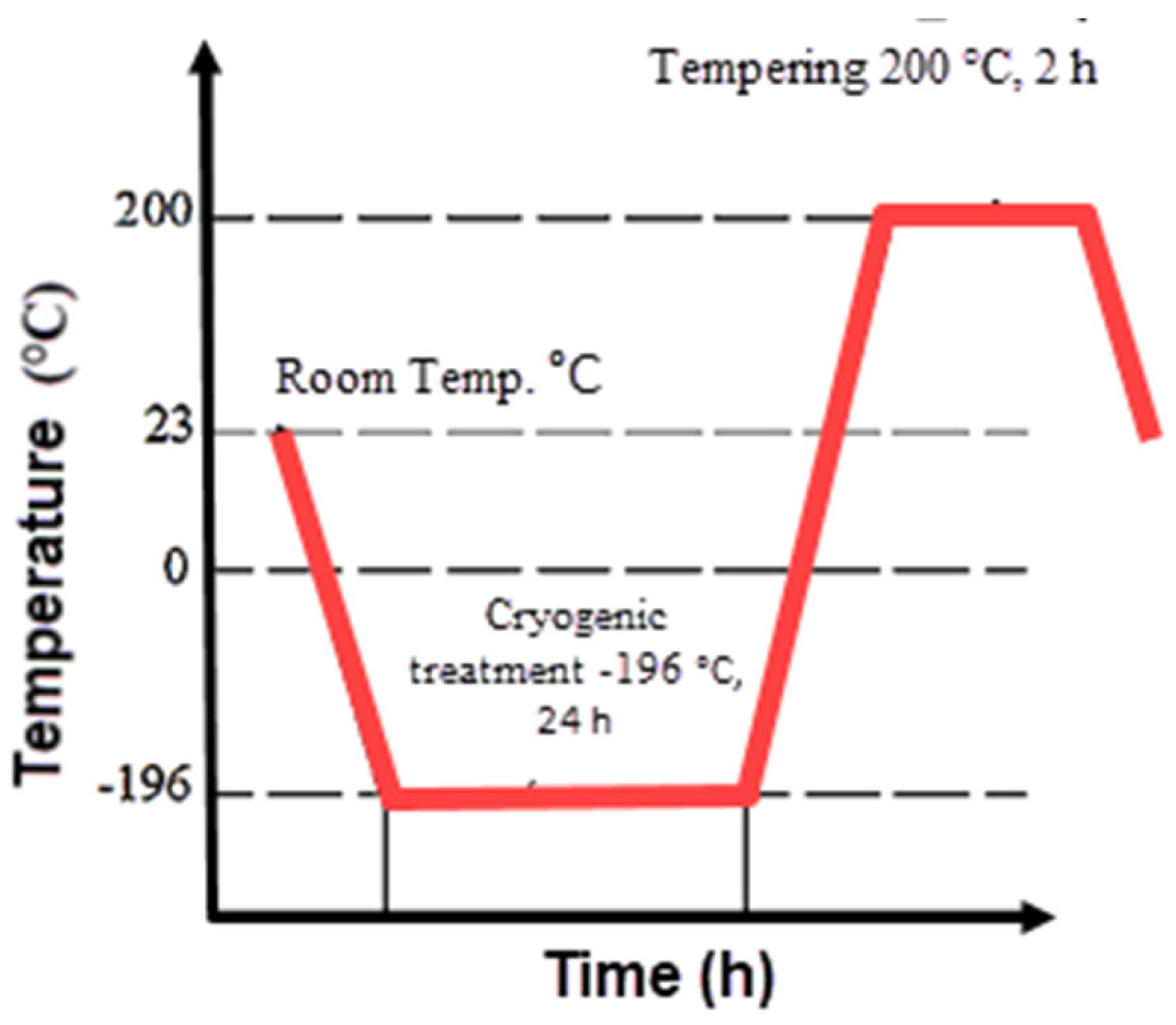
Figure 2.
Experimental setup.
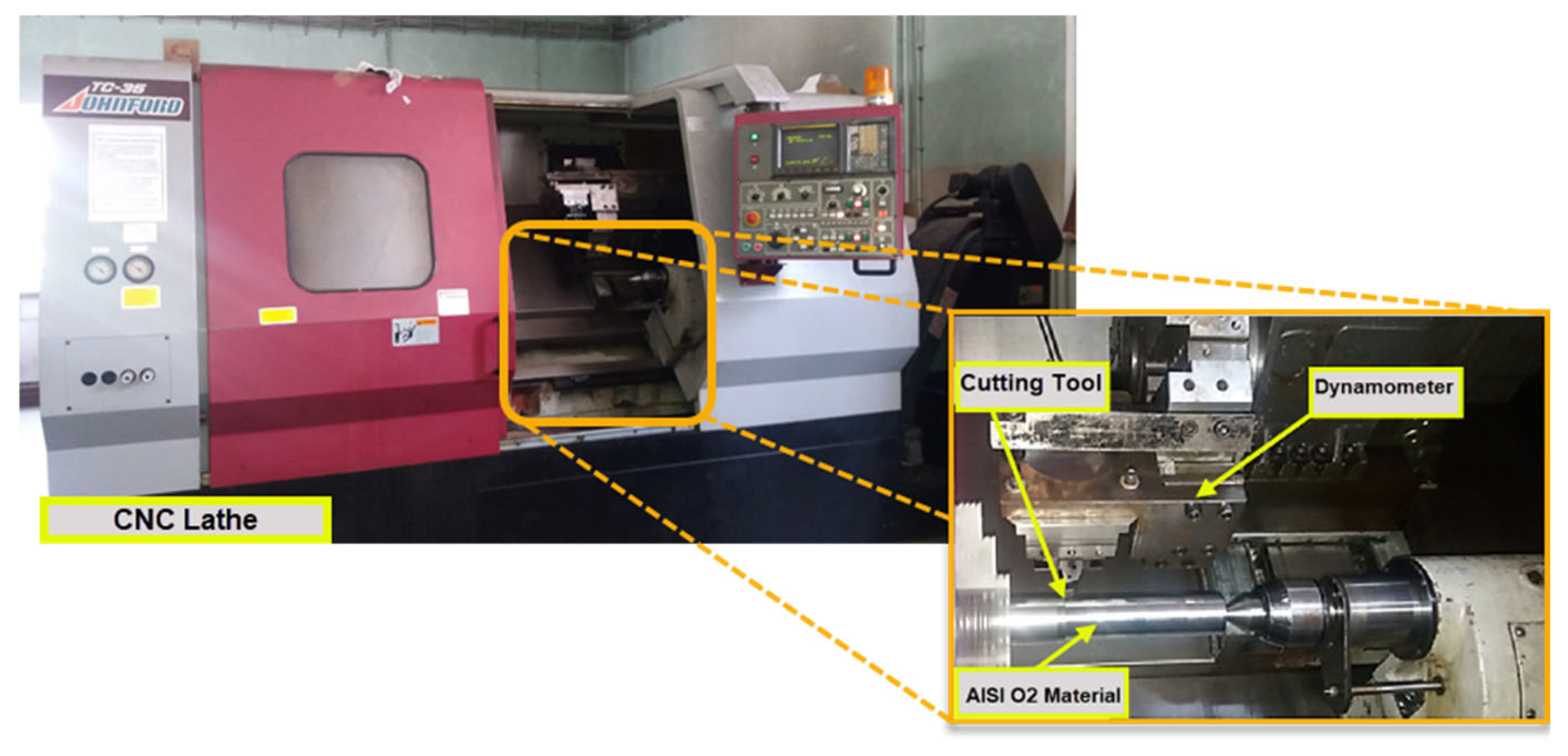
Figure 3.
Effect of control factors on Fc.
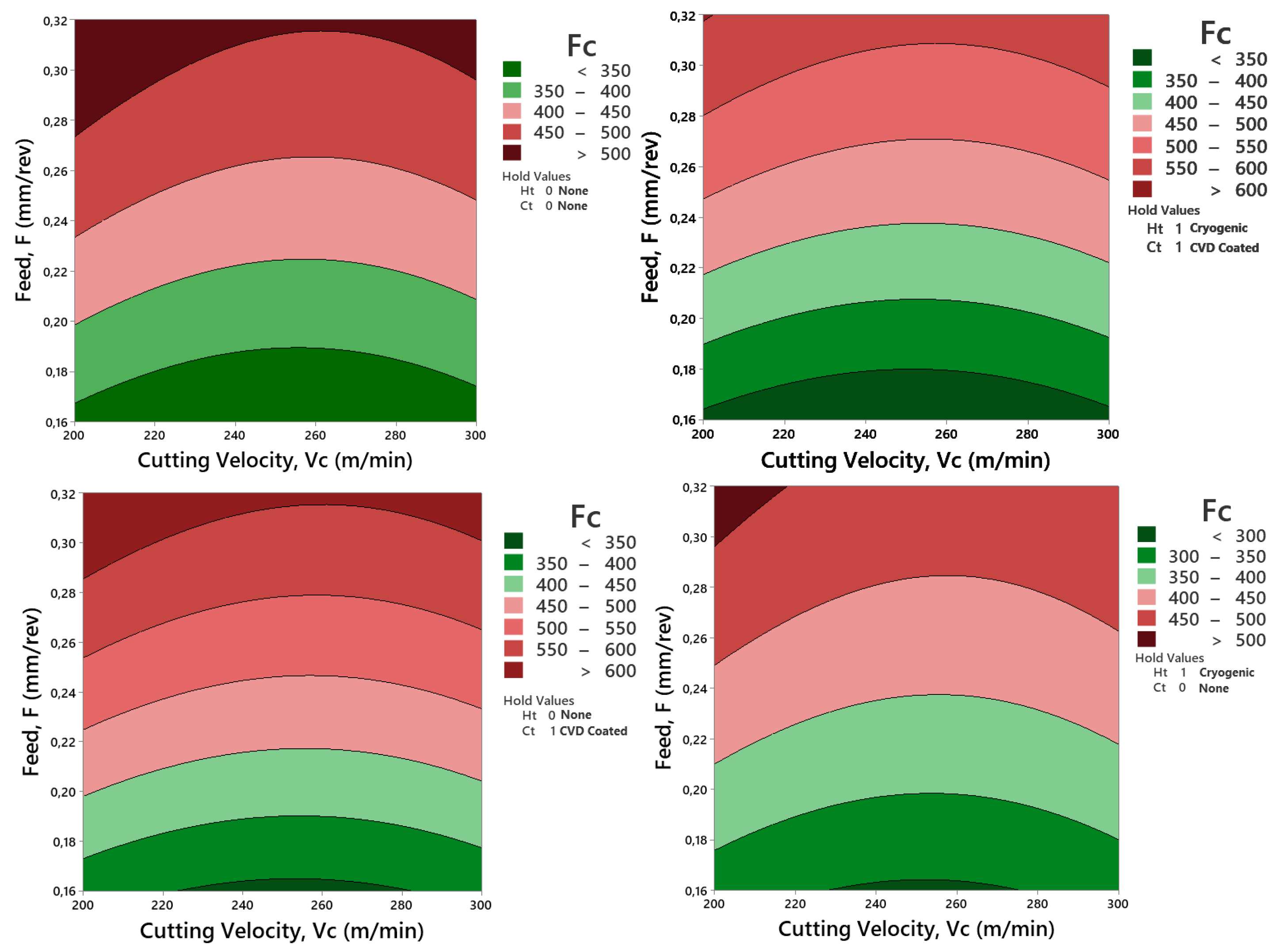
Figure 4.
Comparison of experimental and estimated values of Fc.
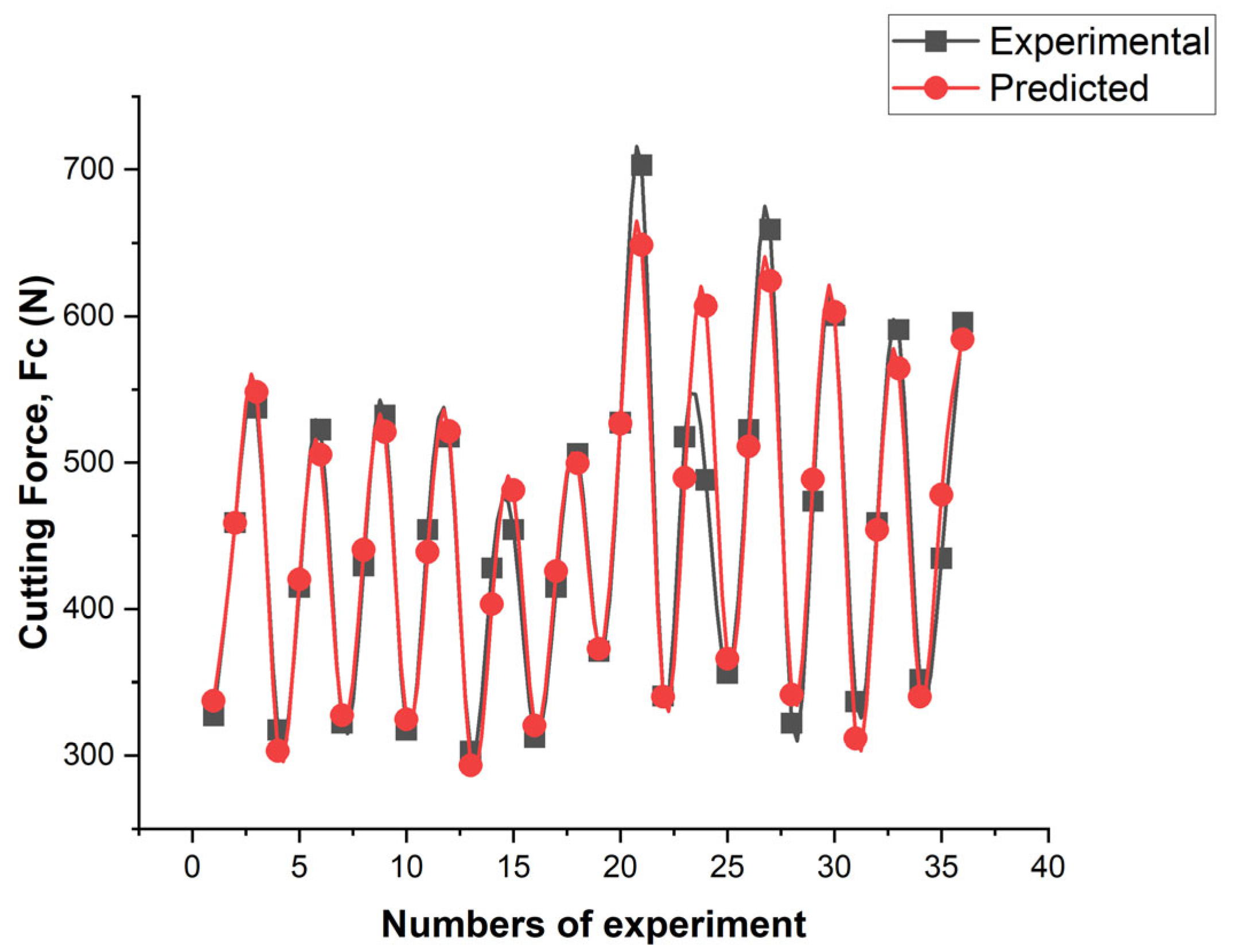
Figure 5.
Effect of control factors on Ra.
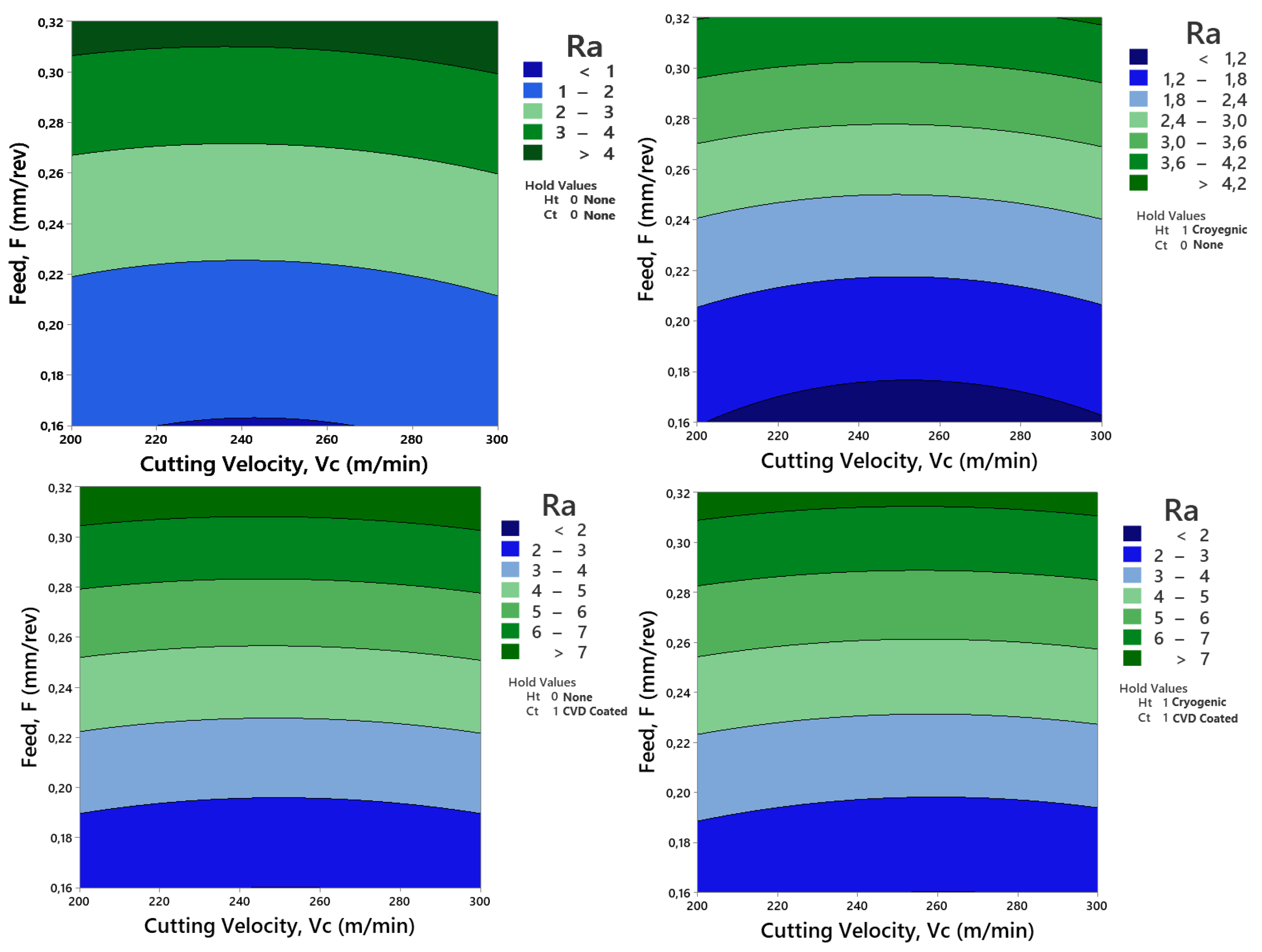
Figure 6.
Comparison of experimental and estimated values of Ra.
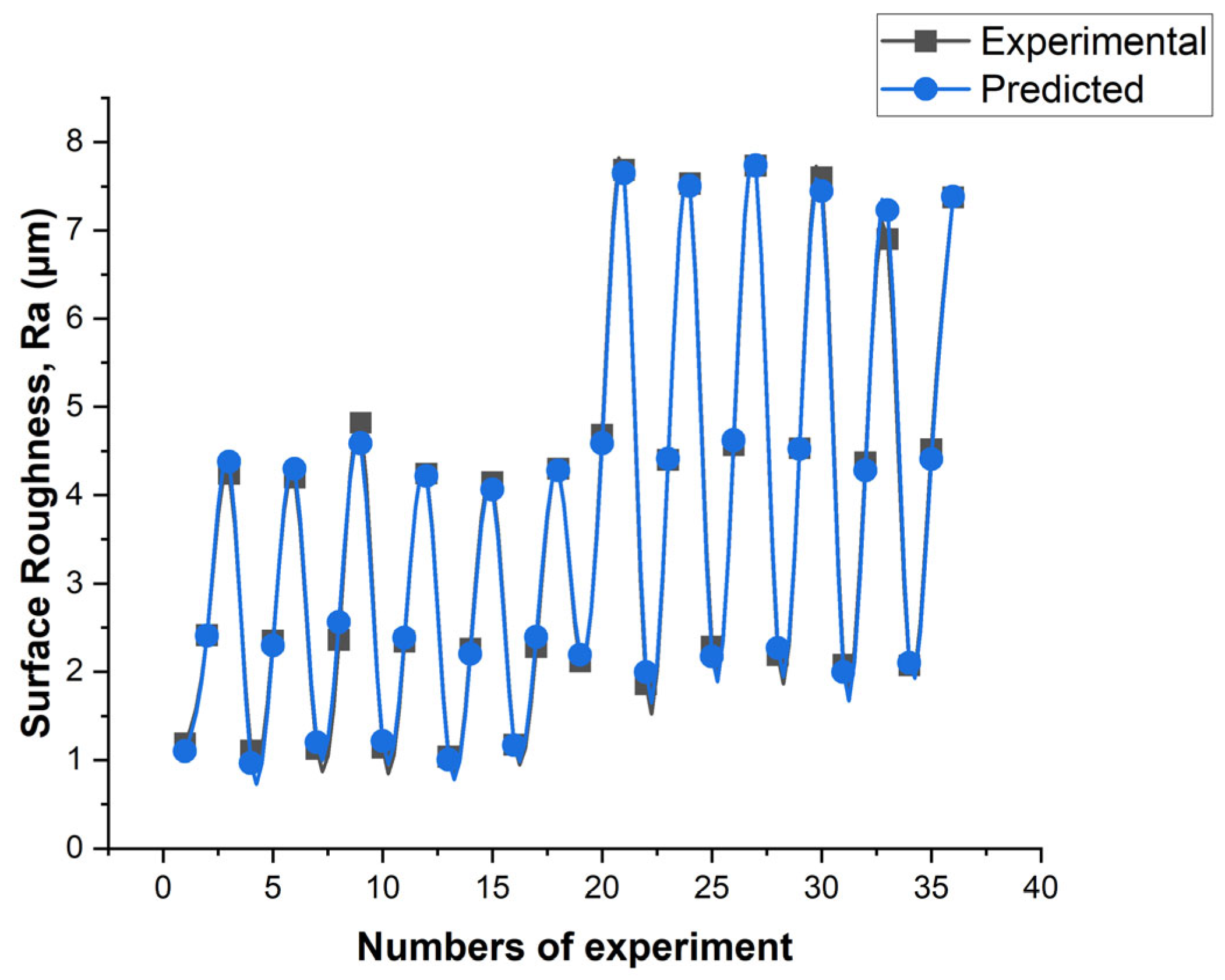
Figure 7.
Nose wear over time at a) 0.08 mm/rev feed rate, b) 0.16 mm/rev feed rate at 200 m/min cutting speed.
Figure 7.
Nose wear over time at a) 0.08 mm/rev feed rate, b) 0.16 mm/rev feed rate at 200 m/min cutting speed.
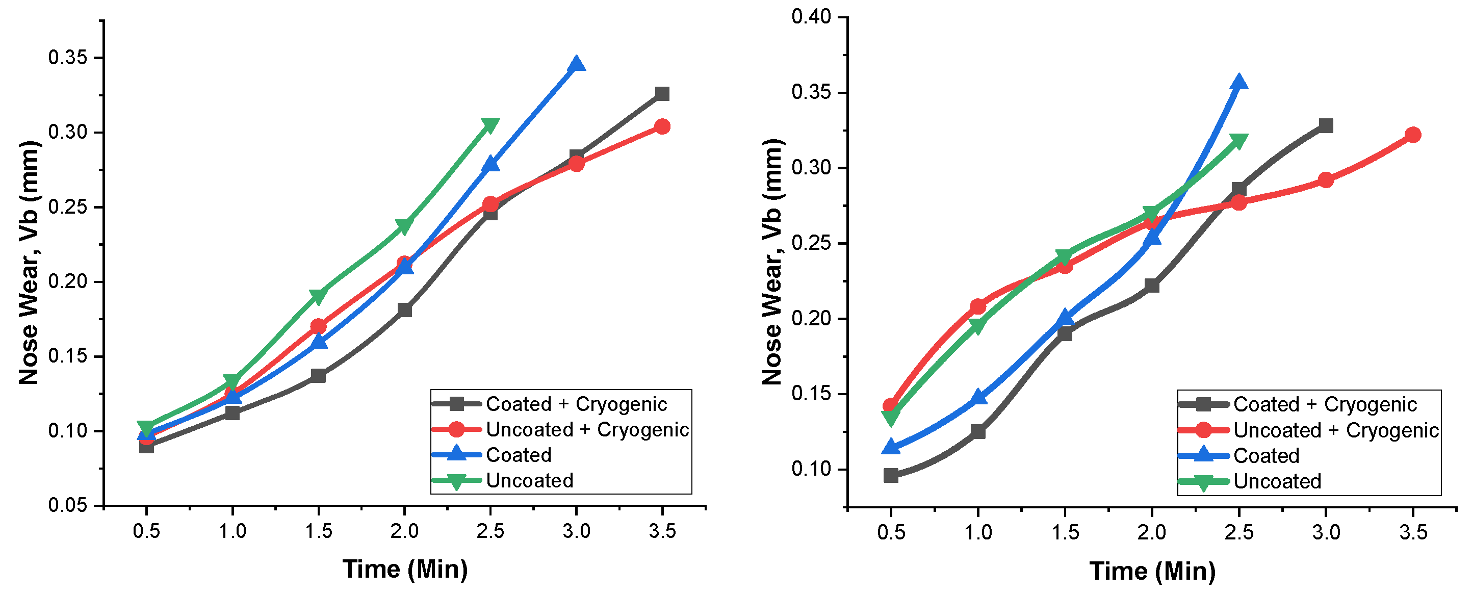
Figure 8.
Nose wear over time at a cutting speed of 250 m/min a) 0.08 mm/rev feed rate, b) 0.16 mm/rev feed rate.
Figure 8.
Nose wear over time at a cutting speed of 250 m/min a) 0.08 mm/rev feed rate, b) 0.16 mm/rev feed rate.
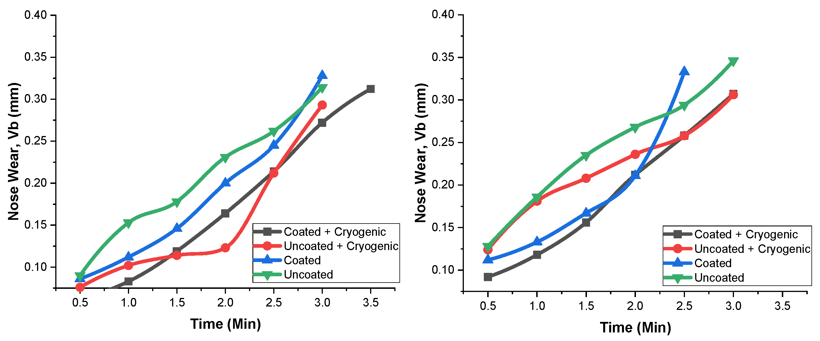
Figure 9.
Wear experienced by uncoated cutting tools at a cutting speed of 250 m/min and a feed rate of 0.16 mm/rev. a) Cutting tool without cryogenic treatment b) Cutting tool with cryogenic treatment.
Figure 9.
Wear experienced by uncoated cutting tools at a cutting speed of 250 m/min and a feed rate of 0.16 mm/rev. a) Cutting tool without cryogenic treatment b) Cutting tool with cryogenic treatment.
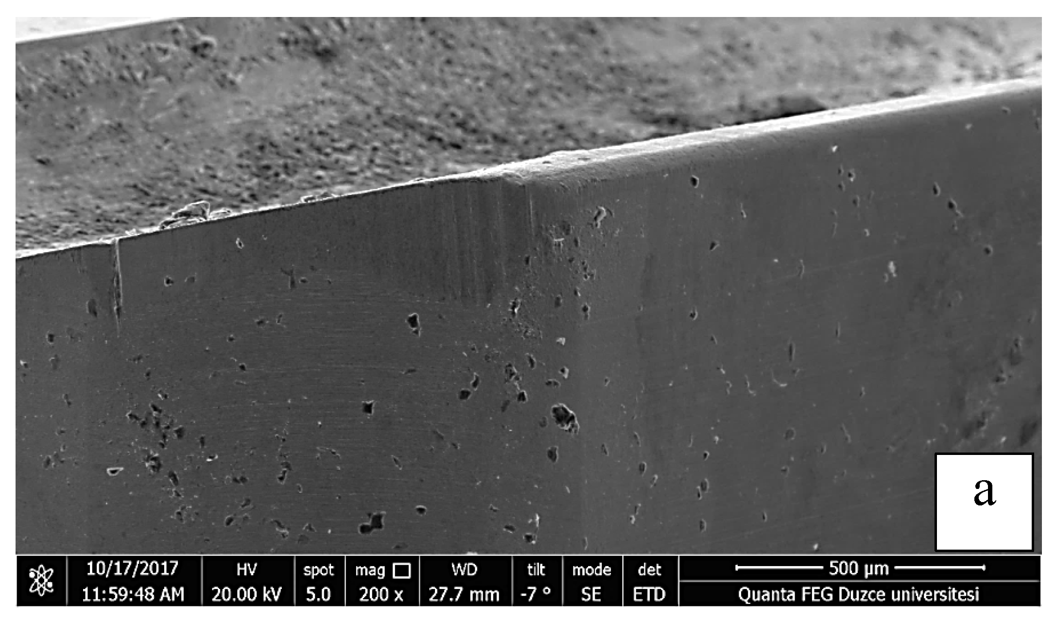
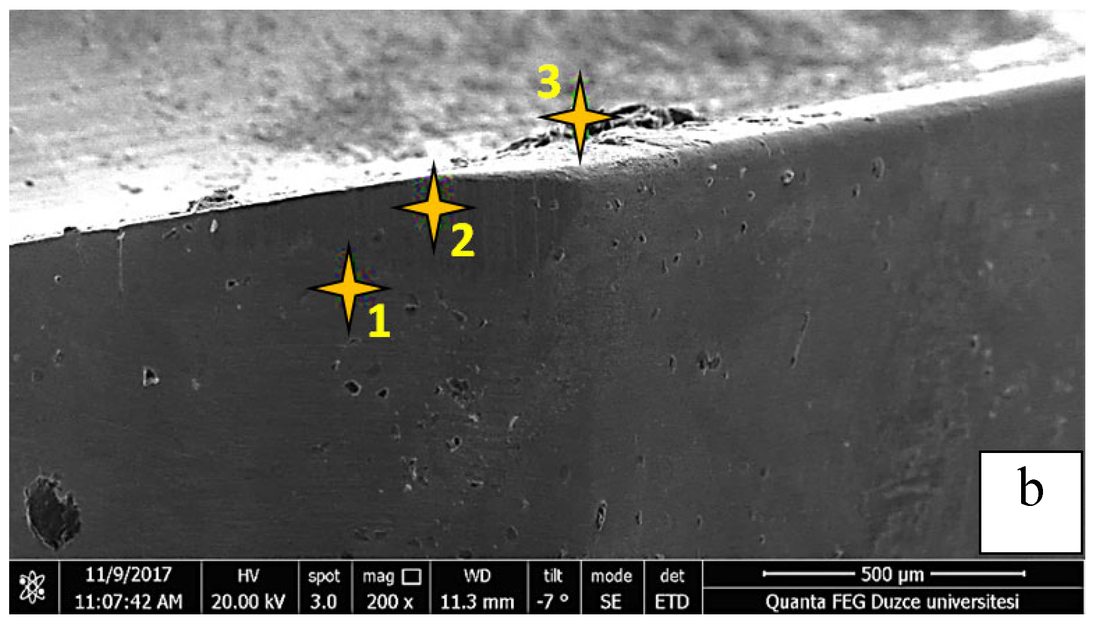
Figure 10.
EDX analysis of regions 1, 2, and 3 formed at 250 m/min cutting speed and 0.16 mm/rev feed rate for the cryogenically treated uncoated cutting tool.
Figure 10.
EDX analysis of regions 1, 2, and 3 formed at 250 m/min cutting speed and 0.16 mm/rev feed rate for the cryogenically treated uncoated cutting tool.
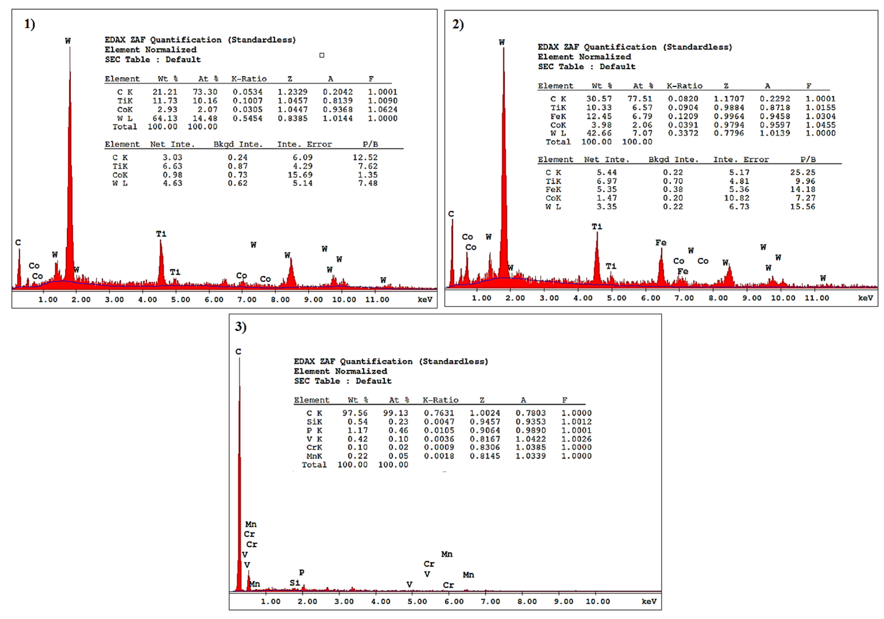
Figure 11.
Wear image of the coated cutting tool that was not cryogenically treated at a cutting speed of 200 m/min and a feed rate of 0.08 mm/rev.
Figure 11.
Wear image of the coated cutting tool that was not cryogenically treated at a cutting speed of 200 m/min and a feed rate of 0.08 mm/rev.
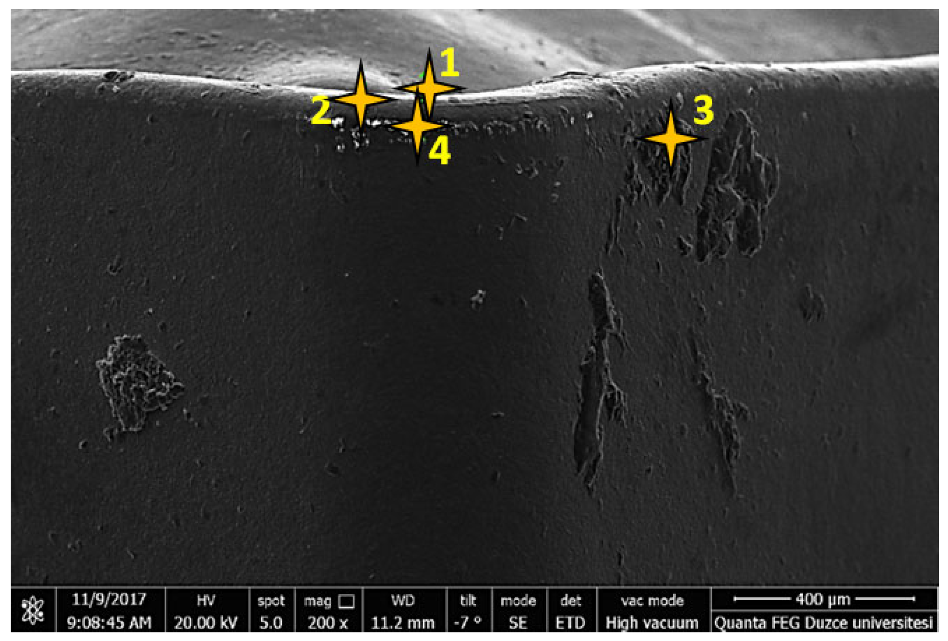
Figure 12.
EDX analysis of regions 1, 2, 3, and 4 occurring at 200 m/min cutting speed and 0.08 mm/rev feed rate for the coated cutting tool that has not been cryogenically treated.
Figure 12.
EDX analysis of regions 1, 2, 3, and 4 occurring at 200 m/min cutting speed and 0.08 mm/rev feed rate for the coated cutting tool that has not been cryogenically treated.
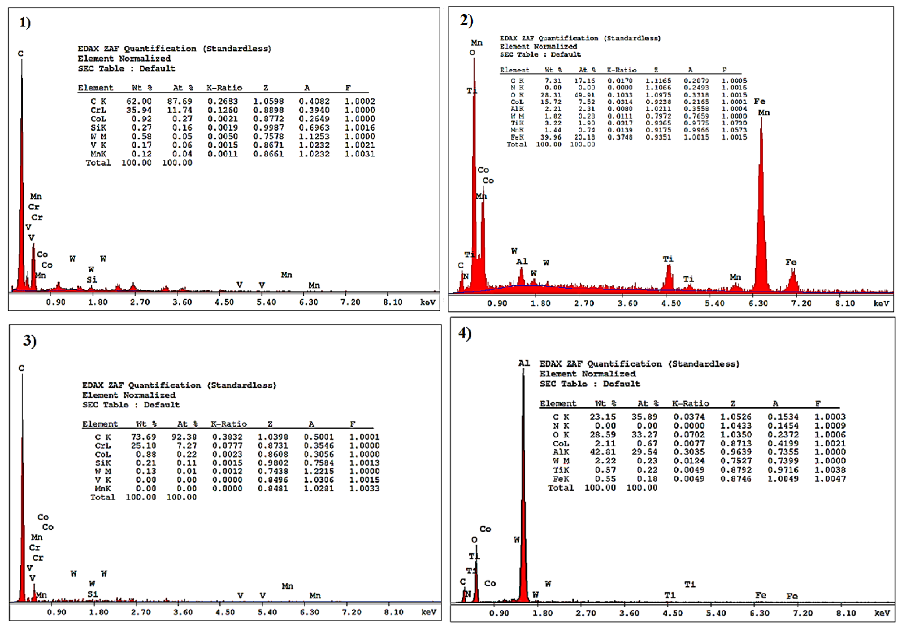
Figure 13.
SEM image of coated cutting tool subjected to cryogenic treatment at 200 m/min cutting speed and 0.16 rpm feed.
Figure 13.
SEM image of coated cutting tool subjected to cryogenic treatment at 200 m/min cutting speed and 0.16 rpm feed.
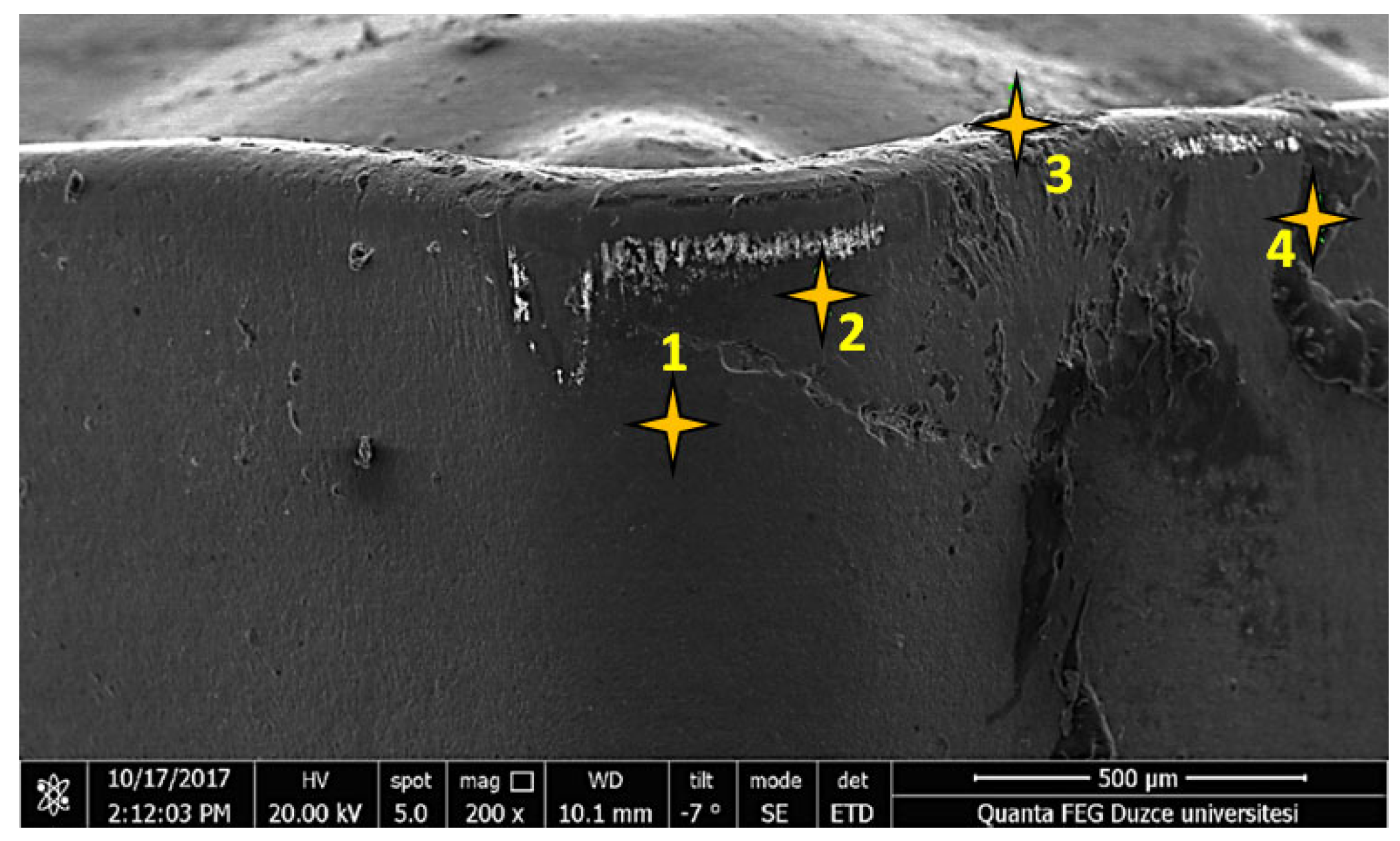
Figure 14.
EDX analysis in regions 1, 2, 3, and 4 formed at 200 m/min cutting speed and 0.16 mm/rev feed rate for the cryogenically treated coated cutting tool.
Figure 14.
EDX analysis in regions 1, 2, 3, and 4 formed at 200 m/min cutting speed and 0.16 mm/rev feed rate for the cryogenically treated coated cutting tool.
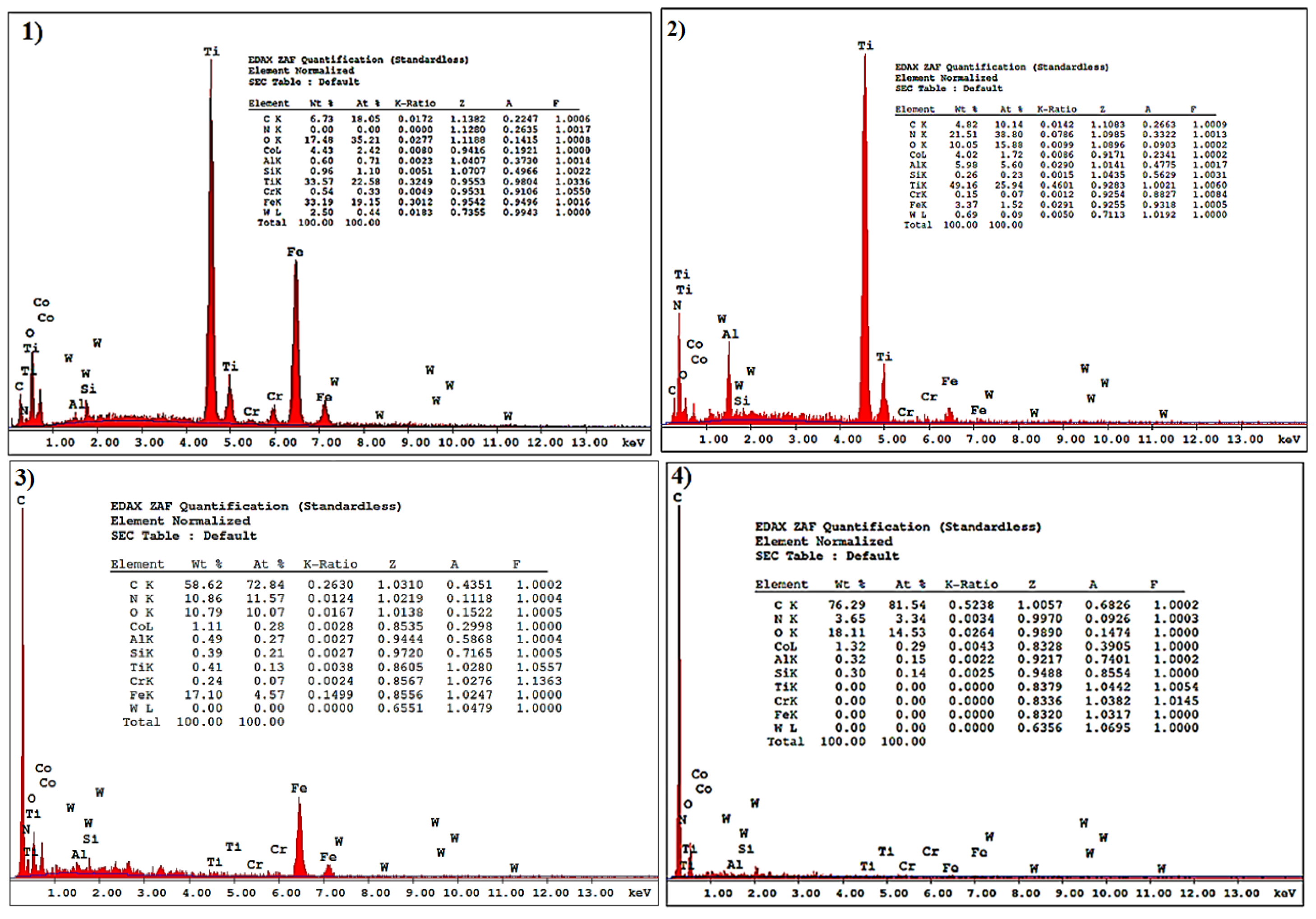
Figure 15.
XRD diagrams of deeply etched cutting tools.
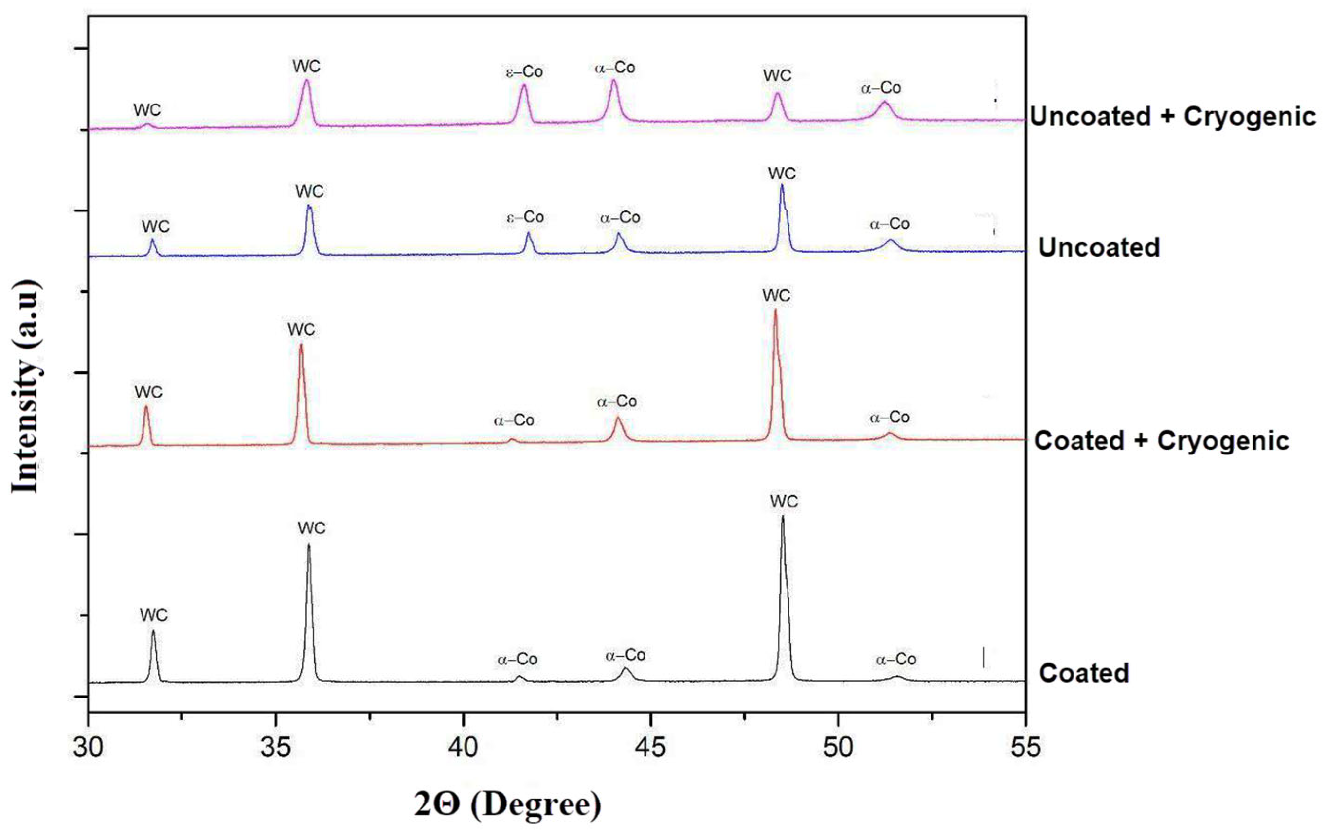
Figure 16.
Hardness effect of cryogenic treatment on cutting tools.
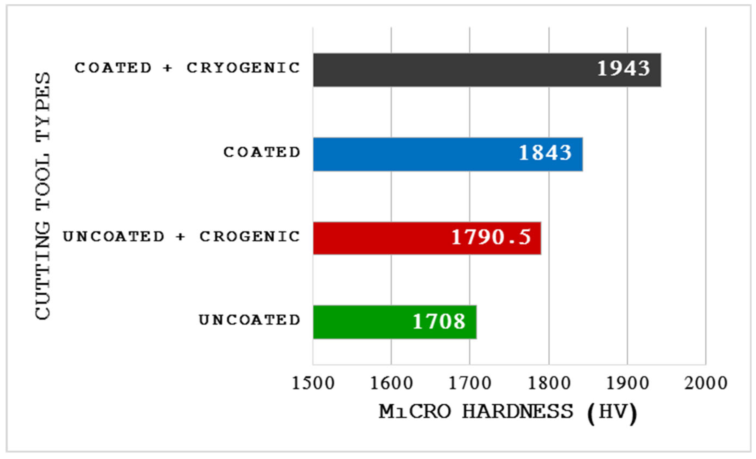

Table 1.
Chemical composition of AISI O2 steel (% by weight).
| C | Si | Mn | Cr | V |
|---|---|---|---|---|
| 0.90 | 0.25 | 2.00 | 0.35 | 0.10 |
Table 2.
Experimental parameters.
| Heat treatment, (Ht) | Coating type, (Ct) | Cutting speed, m/min, (Vc) | Feed rates, mm/rev, (f) |
|---|---|---|---|
| Deep Cryogenic | CVD Coated | 200 | 0.16 |
| None | None | 250 | 0.24 |
| 300 | 0.32 |
Table 3.
Control and output parameters used for RSM optimization.
| Exp. No. | Control Factors | Output Parameters | ||||
|---|---|---|---|---|---|---|
| Heat Treatment | Coating Type | Cutting speed, (Vc), m/min | Feed rates (f), mm/rev | Surface Roughness (Ra) µm | Cutting Force (Fc), N | |
| 1 | None | None | 200 | 0.16 | 1.188 | 327.14 |
| 2 | None | None | 200 | 0.24 | 2.4137 | 458.98 |
| 3 | None | None | 200 | 0.32 | 4.2437 | 537.10 |
| 4 | None | None | 250 | 0.16 | 1.106 | 317.38 |
| 5 | None | None | 250 | 0.24 | 2.351 | 415.03 |
| 6 | None | None | 250 | 0.32 | 4.199 | 522.46 |
| 7 | None | None | 300 | 0.16 | 1.126 | 322.16 |
| 8 | None | None | 300 | 0.24 | 2.362 | 429.68 |
| 9 | None | None | 300 | 0.32 | 4.817 | 532.22 |
| 10 | Cryogenic | None | 200 | 0.16 | 1.141 | 317.38 |
| 11 | Cryogenic | None | 200 | 0.24 | 2.34 | 454.10 |
| 12 | Cryogenic | None | 200 | 0.32 | 4.2457 | 517.57 |
| 13 | Cryogenic | None | 250 | 0.16 | 1.04 | 302.73 |
| 14 | Cryogenic | None | 250 | 0.24 | 2.2623 | 428.16 |
| 15 | Cryogenic | None | 250 | 0.32 | 4.147 | 454.10 |
| 16 | Cryogenic | None | 300 | 0.16 | 1.1737 | 312.50 |
| 17 | Cryogenic | None | 300 | 0.24 | 2.278 | 415.03 |
| 18 | Cryogenic | None | 300 | 0.32 | 4.3017 | 506.12 |
| 19 | None | CVD | 200 | 0.16 | 2.116 | 371.09 |
| 20 | None | CVD | 200 | 0.24 | 4.684 | 527.34 |
| 21 | None | CVD | 200 | 0.32 | 7.684 | 703.12 |
| 22 | None | CVD | 250 | 0.16 | 1.857 | 340.62 |
| 23 | None | CVD | 250 | 0.24 | 4.4023 | 517.57 |
| 24 | None | CVD | 250 | 0.32 | 7.529 | 488.28 |
| 25 | None | CVD | 300 | 0.16 | 2.288 | 356.44 |
| 26 | None | CVD | 300 | 0.24 | 4.5673 | 522.34 |
| 27 | None | CVD | 300 | 0.32 | 7.7323 | 659.17 |
| 28 | Cryogenic | CVD | 200 | 0.16 | 2.1867 | 322.03 |
| 29 | Cryogenic | CVD | 200 | 0.24 | 4.535 | 473.63 |
| 30 | Cryogenic | CVD | 200 | 0.32 | 7.5947 | 600.58 |
| 31 | Cryogenic | CVD | 250 | 0.16 | 2.081 | 336.91 |
| 32 | Cryogenic | CVD | 250 | 0.24 | 4.375 | 458.98 |
| 33 | Cryogenic | CVD | 250 | 0.32 | 6.900 | 590.82 |
| 34 | Cryogenic | CVD | 300 | 0.16 | 2.071 | 351.56 |
| 35 | Cryogenic | CVD | 300 | 0.24 | 4.523 | 434.57 |
| 36 | Cryogenic | CVD | 300 | 0.32 | 7.3743 | 595.93 |
Table 4.
ANOVA output of the relationship between Fc and control parameters.
| Source | DF | Seq SS | Contribution | Adj SS | Adj MS | F-Value | P-Value |
|---|---|---|---|---|---|---|---|
| Model | 12 | 367059 | 93.28% | 367059 | 30588 | 26.60 | 0.000 |
| Linear | 4 | 350415 | 89.05% | 350415 | 87604 | 76.19 | 0.000 |
| Vc | 1 | 1238 | 0.31% | 1238 | 1238 | 1.08 | 0.310 |
| F | 1 | 310431 | 78.89% | 310431 | 310431 | 269.99 | 0.000 |
| Ht | 1 | 6278 | 1.60% | 6278 | 6278 | 5.46 | 0.029 |
| Ct | 1 | 32468 | 8.25% | 32468 | 32468 | 28.24 | 0.000 |
| Square | 2 | 8902 | 2.26% | 8902 | 4451 | 3.87 | 0.036 |
| Vc*Vc | 1 | 6839 | 1.74% | 6839 | 6839 | 5.95 | 0.023 |
| F*F | 1 | 2063 | 0.52% | 2063 | 2063 | 1.79 | 0.193 |
| 2-Way Interaction | 6 | 7742 | 1.97% | 7742 | 1290 | 1.12 | 0.380 |
| Vc*F | 1 | 306 | 0.08% | 306 | 306 | 0.27 | 0.611 |
| Vc*Ht | 1 | 46 | 0.01% | 46 | 46 | 0.04 | 0.843 |
| Vc*Ct | 1 | 12 | 0.00% | 12 | 12 | 0.01 | 0.920 |
| F*Ht | 1 | 305 | 0.08% | 305 | 305 | 0.26 | 0.612 |
| F*Ct | 1 | 6304 | 1.60% | 6304 | 6304 | 5.48 | 0.028 |
| Ht*Ct | 1 | 770 | 0.20% | 770 | 770 | 0.67 | 0.422 |
| Error | 23 | 26445 | 6.72% | 26445 | 1150 | ||
| Total | 35 | 393504 | 100.00% |
Table 5.
Second-order estimation equations of Fc for different combinations of Ht and Ct.
| Ht | Ct | Equation |
|---|---|---|
| None | None | |
| Cryogenic | None | |
| None | CVD | |
| Cryogenic | CVD |
Table 6.
Response optimization for Fc.
| Inputs | Optimum Machining Parameters | RSM Prediction | ||||||||
|---|---|---|---|---|---|---|---|---|---|---|
| Parameter | Goal | Vc, (m/min) | f, (mm/rev) | Ht | Ct | Lower | Target | Predicted response | Upper | Desirability |
| Fc (N) | Minimum | 252.525 | 0.16 | None | CVD | 302.73 | 302.73 | 339.99 | 703.12 | 0.906 |
Table 7.
ANOVA output of the relationship between Ra and control parameters.
| Source | DF | Seq SS | Contribution | Adj SS | Adj MS | F-Value | P-Value |
|---|---|---|---|---|---|---|---|
| Model | 12 | 158.219 | 99.74% | 158.219 | 13.185 | 739.09 | 0.000 |
| Linear | 4 | 149.797 | 94.43% | 149.797 | 37.449 | 2099.25 | 0.000 |
| Vc | 1 | 0.002 | 0.00% | 0.002 | 0.002 | 0.14 | 0.715 |
| F | 1 | 110.056 | 69.38% | 110.056 | 110.056 | 6169.29 | 0.000 |
| Ht | 1 | 0.122 | 0.08% | 0.122 | 0.122 | 6.84 | 0.015 |
| Ct | 1 | 39.616 | 24.97% | 39.616 | 39.616 | 2220.72 | 0.000 |
| Square | 2 | 1.159 | 0.73% | 1.159 | 0.579 | 32.48 | 0.000 |
| Vc*Vc | 1 | 0.280 | 0.18% | 0.280 | 0.280 | 15.68 | 0.001 |
| F*F | 1 | 0.879 | 0.55% | 0.879 | 0.879 | 49.28 | 0.000 |
| 2-Way Interaction | 6 | 7.264 | 4.58% | 7.264 | 1.211 | 67.86 | 0.000 |
| Vc*F | 1 | 0.012 | 0.01% | 0.012 | 0.012 | 0.65 | 0.429 |
| Vc*Ht | 1 | 0.033 | 0.02% | 0.033 | 0.033 | 1.83 | 0.190 |
| Vc*Ct | 1 | 0.022 | 0.01% | 0.022 | 0.022 | 1.25 | 0.276 |
| F*Ht | 1 | 0.114 | 0.07% | 0.114 | 0.114 | 6.39 | 0.019 |
| F*Ct | 1 | 7.080 | 4.46% | 7.080 | 7.080 | 396.87 | 0.000 |
| Ht*Ct | 1 | 0.003 | 0.00% | 0.003 | 0.003 | 0.18 | 0.673 |
| Error | 23 | 0.410 | 0.26% | 0.410 | 0.018 | ||
| Total | 35 | 158.629 | 100.00% |
Table 8.
Second-order predictive equations of Ra for different combinations of Ht and Ct.
| Ht | Ct | Equation |
|---|---|---|
| None | None | |
| Cryogenic | None | |
| None | CVD | |
| Cryogenic | CVD |
Table 9.
Response optimization for Ra.
| Inputs | Optimum Machining Parameters | RSM Prediction | ||||||||
|---|---|---|---|---|---|---|---|---|---|---|
| Parameter | Goal | Vc, (m/min) | f, (mm/rev) | Ht | Ct | Lower | Target | Predicted response | Upper | Desirability |
| Ra (µm) | Minimum | 243.434 | 0.16 | None | None | 1.04 | 1.04 | 0.96 | 7.7323 | 0.960 |
Table 10.
Ratios of α–Co and Ɛ–Co phases calculated as a result of Rietveld analysis and percentage change of Ɛ–Co.
Table 10.
Ratios of α–Co and Ɛ–Co phases calculated as a result of Rietveld analysis and percentage change of Ɛ–Co.
| Coated | Coated + Cryogenic | Uncoated | Uncoated + Cryogenic | |
|---|---|---|---|---|
| α-Co (%) | 21.353 | 36.542 | 26.421 | 34.463 |
| Ɛ–Co (%) | 8.768 | 11.410 | 18.142 | 27.332 |
Disclaimer/Publisher’s Note: The statements, opinions and data contained in all publications are solely those of the individual author(s) and contributor(s) and not of MDPI and/or the editor(s). MDPI and/or the editor(s) disclaim responsibility for any injury to people or property resulting from any ideas, methods, instructions or products referred to in the content. |
© 2024 by the authors. Licensee MDPI, Basel, Switzerland. This article is an open access article distributed under the terms and conditions of the Creative Commons Attribution (CC BY) license (http://creativecommons.org/licenses/by/4.0/).
Copyright: This open access article is published under a Creative Commons CC BY 4.0 license, which permit the free download, distribution, and reuse, provided that the author and preprint are cited in any reuse.


