Submitted:
07 April 2025
Posted:
08 April 2025
You are already at the latest version
Abstract
Tools with microtextures have found wide application in cutting difficult machining materials. The cutting performance of tools is closely related to the arrangement, morphology, and size parameters of microtextures. In this research micro-pit tools were used in turning GH4169 in spray cooling. The effect of micro-pit parameters on tool wear was investigated through simulation and cutting experiment. In simulation, a model of cutting GH4169 in spray cooling was built to analyze the wear of micro-textured tools with different parameters, and the optimal combination of micro-pit parameters with excellent anti-wear performance was obtained. In cutting experiment, micro-pit textures with different parameters were fabricated by femtosecond laser, and cutting experiments were conducted in spray cooling to analyze the wear on the rake face of micro-textured tools. Furthermore, Ansys Fluent was used to simulate the dynamic pressure of oil film on the surface of micro-pits and the anti-wear mechanism of micro-textured tools was verified. This research provides technical reference for the design and development of micro-textured tools.
Keywords:
micro-textured tools
; micro-pit parameters
; tool wear
; spray cooling
; GH4169
1. Introduction
Nickel-based superalloy GH4169 possesses comprehensive properties including high toughness, high strength, good wear resistance, corrosion resistance, and high-temperature oxidation resistance, making it widely used in aerospace, nuclear, and petroleum industries [1,2]. However, due to its high-temperature strength, low thermal conductivity, and high plasticity, the high cutting temperatures and cutting forces occurred in machining may easily lead to work hardening. As a result, a severe tool wear and a reduced tool life are liable to happen to its processing [3]. In recent years, researchers have introduced various methods to improve tool wear resistance, with tool modification and cooling condition optimization showing significant effects [4]. Therefore, the use of appropriate cutting tools and cooling methods is critical for the reduction of cutting temperature, the decrease of tool wear and a prolonged tool life in machining GH4169 [5].
As minimal quantity lubrication (MQL) technology, spray cooling demonstrates remarkable advantages among all the cooling methods. It delivers pressurized cutting fluid in an atomized mist form to the cutting zone, effectively and uniformly enhancing heat transfer to achieve superior cooling and lubrication. This approach not only reduces tool wear but also minimizes cutting fluid consumption for improved environmental sustainability. Jiawei Deng et al. conducted turning experiments on nickel-based superalloy GH4169 in dry cutting, MQL and nanofluid MQL conditions respectively. It is revealed that nanofluid MQL technology significantly reduces cutting force, cutting temperature, and tool wear [6]. Ramanuj Kumar et al. investigated the turning of AISI D2 steel with carbide tools in impingement spray cooling. Results show that the evaporation of atomized cutting fluid provides remarkable cooling effects and a lower tool temperature and reduce wear can be achieved [7]. Qinglong An et al. compared cold mist jet with cold air jet, flood cooling, and MQL in machining titanium alloy. It is proved that cold mist jet offers better cooling capacity that substantially reduces cutting temperature in high-speed titanium machining while improving tool life and surface quality [8]. Bangfu Wu et al. studied tool wear behavior when milling ultra-high-strength steel in different cooling conditions. The experiments show that ultrasonic atomization of cutting fluid achieved the best anti-wear performance of tools and resultant milling force along with an optimal surface quality [9].
In recent years, the design of micro-textured cutting tools based on bionics has attracted extensive attention from researchers worldwide. By precision machining techniques including electrical discharge machining (EDM), photolithography, and laser processing, optimized geometric patterns and structural arrangements can be fabricated on rake face of tools to obtain improved cutting property. Many scholars have investigated the cutting performance of micro-textured tools through cutting experiments and finite element analysis. Yuanyuan Li et al. conducted cutting simulation research on 6061 aluminum alloy cut by non-textured tools and micro-textured tools as well. Results indicate that the micro-textured features on tools can effectively reduce friction between chips and the tool rake face, thereby reducing frictional heat and lowering cutting temperature [10]. Zhenglong Fang et al. compared tool wear, material adhesion and chip formation in turning nickel-based superalloys cut by micro-textured tools and non-textured tools and micro-textured tools exhibit superior cutting performance [11]. Mustapha Mukhtar Usman et al. performed comparative turning experiments on 304 stainless steel cut by micro-textured tools, investigating the cutting performance of micro-textured tools in both ultrasonic elliptical vibration cutting and conventional cutting conditions. The experimental results showed that micro-textured tools outperform non-textured tools in overall machining performance [12]. Sharma et al. reviewed the tribological advantages of texture surfaces. The research shows that tools with micro-pits or linear grooves can effectively reduce cutting force, friction coefficient and lower cutting temperature while extending tool life [13]. Darshan et al. fabricated pit-pattern textured tools and confirmed that compared to non-textured tools, the textured tools reduced cutting force and rake face wear while improving workpiece surface quality [14].
Studies from both home and abroad demonstrate that the performance of micro-textured tools is primarily governed by three key factors: texture morphology, arrangement patterns, and dimensional parameters.
In terms of texture morphology, Kawasegi N fabricated transverse and longitudinal micro-grooves on WC-Co carbide turning tools to investigate texture orientation effects when machining aluminum alloy Al5052. Results show that textures perpendicular to chip flow direction reduce cutting forces, whereas parallel textures generate forces comparable to or slightly higher than non-textured tools [15]. Hui Yang developed two bionics-based textures (U-shaped grooves and diamond pits) on carbide tools for machining 45 steel, with comparative wear analysis revealing distinct tribological properties and cutting performance across texture morphologies [16]. Guolong Wu engineered three textures (pit, groove, and mesh) for tribological property research, identifying laser texturing as an effective method to reduce friction and wear [17].
Regarding the arrangement patterns of micro-textures, Xin Yu et al. proposed a design of micro-textures with different density distributions to adapt to different friction state in the tool-chip interface, and maintain excellent friction reduction and wear resistance as well. After turning experiments on superalloy GH4202, the results demonstrate that parameters of textures in different area of rake face are related to the machining performance and mechanisms. Compared with non-textured tools and uniformly distributed textured tools, the properly designed variable-density textures enabled MTTs to exhibit superior wear resistance and chip-breaking capability in machining GH4202 superalloy [18]. Gajrani K designed various micro-texture arrangements on WC-Co turning tools, including parallel grooves and perpendicular grooves. Cutting experiments on hardened AISI H-13 steel revealed that when chip flow direction remained unchanged, tools with the most number of micro-textures in contact with chips showed significantly reduced cutting and feed forces [19]. Hao X fabricated uniform textures, variable-density textures, combined textures, and variable-density combined textures on triangular carbide turning tools. When machining Ti6Al4V titanium alloy, results indicate that the region close to the cutting edge experiences more severe friction and wear [20]. Sun J studied the effect of mixed texture on the performance of cutting pure iron with carbide cutting tools. In the mixed texture, the grooves can be used as supplement channels of lubricating oil. The grooves are connected to each other, and the lubricant flows along the grooves to the end when squeezed. More lubricant stays near the cutting edge and less lubricant is found between the adjacent grooves. In contrast, pit-texture provides a relatively enclosed space, lubricant flows from the edge of the pit to the surrounding areas. The oil supply along the cutting edge comes only from limited numbers of pits, which is difficult to meet the demand. The design of mixed textures combines the advantages of both groove and pit textures to achieve a uniform coating of the lubricating oil. The design improves the cutting performance of the tool [21].
Research on dimensional parameters of micro-texture also received attention. Hossam A. Kishawy et al. proposed a novel mechanism to describe their influence on cutting performance. The study revealed that among various parameters, the distribution and width of micro-grooves exhibited the most significant effects. When micro-grooves were located farthest from the cutting edge (200μm) with the narrowest width (30μm), the cutting force reached its minimum; conversely, the maximum cutting force occurred when micro-grooves were closest to the cutting edge (50μm) with the widest dimension (60μm). Comparatively, optimally parameterized micro-textured tools achieved a 12% reduction in cutting force [22]. Qinghua Li investigated micro-texture effects on polycrystalline cubic boron nitride tools when machining hardened GCr15 steel in term of tool wear and surface roughness. The team designed two different micro-pit textures with identical pit-depth of 5μm. Results indicate that micro-pits with d=80μm outperformed those with d=120μm in improving surface quality and reducing tool wear [23]. Zhao Zhen engineered micro-grooves on the flank face of YG6 carbide turning tools. The 20μm-depth grooves were parallel to the tool edge and approximately 50μm from the main cutting edge. Nine combinations were created by varying groove widths (20μm, 40μm, 60μm) and spacings (50μm, 70μm, 90μm). Turning experiments on zirconia ceramic rods confirm that flank-face textured tools with optimized parameters significantly decrease cutting forces and reduce tool wear [24].
Extensive research from domestic and foreign scholars has demonstrated that the use of micro-textured cutting tools in machining effectively lowers cutting temperatures and reduces cutting forces while improving surface quality and extending tool life. However, few studies are found currently on micro-textured tools when machining superalloys in spray cooling. Investigating the influence of micro-texture parameters on tool wear resistance holds significant importance and warrants further exploration. In this study, turning experiments were conducted on nickel-based superalloy GH4169 using micro-pit textured tools with varying parameters in spray cooling. The research analyzes the effects of micro-pit parameters on tool wear, identifies predominant wear patterns and mechanisms, and provides technical support for the design optimization of micro-textured tools.
2. Design of Micro-Texture Parameters of Pits
2.1. Micro-Pit Parameter and Distribution of Pit-Texture
Some previous studies on texture morphologies were conducted by the research team. The experiment and simulation results show that micro-pit textured tools exhibit the smallest variation range in wear depth compared to tools with other texture morphologies. The studies also demonstrate that the wear area on rake face of those textured tools displays a fan-shaped distribution—wider near the tool nose and progressively narrowing with increasing distance from the tool nose, with the maximum wear depth occurring farther from the tool nose [25].
Accordingly, this study designed fan-distributed micro-pit textures as shown in Figure 1. The three dimensional parameters include: the distance from the top micro-pit to the tool nose (Parameter A, termed as edge distance), the diameter of micro-pits (Parameter B), and the pit spacing (Parameter C).
2.2. Micro-Pit Textured Tools and Their Numbering
The designed micro-pit textured tools with different texture parameters are shown in Table 1. Tool No.1 is a non-textured tool. All the micro-pits were processed in depth of 30 μm.
3. Simulation Analysis of Tool Wear with Different Micro-Pit Parameters
3.1. Establishment of Cutting Simulation Model of Micro-Pit Textured Tool
3.1.1. Construction of Cutting Geometric Model
A geometric model of micro-pit tools was established in a 1:1 scale in Deform-3D module. A mesh refinement of the pit textures was carried out. To improve simulation efficiency, the cylindrical workpiece was simplified into a thin-walled annular rotating body and the tool was simplified into the part of tool nose. The simplification of cutting model is illustrated in Figure 2.
3.1.2. Workpiece Material Model
In corresponding to GH4169, Inconel718 in the American material grade was selected to be used in simulation. In view of the strain hardening, strengthening and thermalization of material, the constitutive model Johnson-Cook is applied to the simulation to provide cutting conditions similar to the real ones. The mathematical expression of for the constitutive model was shown in Equation (1).
In the Equation, is the flow stress; is the equivalent plastic strain; is the equivalent plastic strain rate; T is time.
3.1.3. Tool-Chip Friction Model
This simulation examined the cutting process of nickel-based superalloys using carbide micro-textured tools. In machining, tool nose heated up faster than the rake face of the tool, and a temperature gradient was formed, the normal stress ratio dropped, and a sliding friction between the tool and chips occurred. To ensure simulation accuracy, a mixed-slip friction model was adopted, with its mathematical formulation provided in Equation (2).
In the Equation, Tf is friction stress; is normal stress; μ is friction coefficient. This simulation takes μ as 0.6; is the ultimate shear stress of workpiece.
3.1.4. Tool Wear Model
Being applicable to the process of continuous cutting, Usui model was adopted as tool wear model in this study. This model simulated the real working conditions of high strain rates, temperatures, and substantial pressures. The mathematical formulation of this model is presented in Equation (3).
In the Equation, w is the wear depth; p is the tool-chip interface stress; V is the slip velocity; T is the interface temperature; dt is the time increment; a and b are material constants (a=1×10⁻⁶, b=855) determined by tool material properties.
3.2. Simulation of Spray Cooling
Since the pre-processing module of Deform software cannot directly configure spray cooling parameters, the research team employed ANSYS to model the spray cooling process. Through combined simulation and experimental analysis, the effects of different spray flow rates and pressures on cutting temperature and convective heat transfer coefficient were investigated. Using range analysis with the objective of minimizing cutting temperature, the optimal spray parameter combination was determined. The corresponding convective heat transfer coefficient under these optimal parameters was then imported into Deform to equivalently simulate machining under spray cooling conditions. The optimal spray parameters were identified as: spray pressure is 0.3 MPa, flow rate 3.16 L/h, the corresponding convective heat transfer coefficient is 3137.37 W/(m2·K) [26].
To ensure the comparability of simulation results and minimize interference from other parameter settings, a standardized computational configuration was implemented for all micro-textured tools with different micro-pit parameters. The simulation parameters were uniformly set as follows: total analysis steps of 1500 with a step increment of 0.01, ambient temperature maintained at 20°C, and a constant friction coefficient of 0.6.
3.3. Wear Simulation Analysis of Micro-Pit Textured Tools
To minimize potential errors induced by simulation parameter settings, standardized across all 14 groups of tools designed micro-pit textured tool simulations were identical operating conditions. Maintained constant for all wear simulation tests were the cutting parameters: set at V=90m/min was the cutting speed, fixed at f=0.1mm/r was the feed rate, and kept as ap=0.2mm was the depth of cut. Presented in Figure 3 are the resulting wear simulation cloud diagrams for all 14 groups of tools configurations.
Analyze and organize the variation range of wear depth on the rake face of 14 groups of micro textured tools. The results are shown in Table 2.
Analyzing tools No.1- No.4, it was found that when the pit diameter and pit spacing were fixed and the edge distance was changed (40, 60, 80, 100), the wear depth of the rake face changed the least when the edge distance was 60 μ m. Analyzing tools No.5-No.9, when the edge distance and pit spacing are fixed, changing the pit diameter (30, 40, 50, 60, 70), it is found that as the pit diameter increases, the wear depth of the rake face gradually decreases. When the pit diameter is 70, the change in wear depth of the rake face is the smallest. Analyzing tools No.10- No.13, when the edge distance and the diameter of the pits are fixed and the pit spacing (80, 100, 120, 140) is changed, the wear depth variation range is minimized when the pit spacing is 100 μ m.
According to the tool wear cloud diagram, it is found that the wear depth of No.10 tool is evenly distributed and the change of wear depth is minimal in the area closer to the tool nose than other tools. And the maximum wear depth away from the nose of the tool, such a distribution helps reduce tool wear and increase the service life of the tool. Therefore, the edge distance is 60μm, the pit diameter is 70μm, the pit spacing is 100μm, the corresponding size is the best pit micro-texture, the tool anti-wear effect is the best, the wear distribution is uniform, the wear depth variation range is the smallest.
4. Cutting Experiment in Spray Cooling
4.1. Experimental Design for Spray Cooling Machining Tests
This study conducted turning experiments on nickel-based superalloy GH4169 using micro-pit textured tools in spray cooling conditions, investigating the influence of different micro-pit parameters on tool wear behavior and validating the anti-wear performance of micro-textured tools. A single-factor experiment was adopted, with the edge distance (Parameter A), pit diameter (Parameter B), and pit spacing (Parameter C) serving as independent variables. The tool number and corresponding micro-texture parameters are detailed in Table 1. Based on different combinations of the micro-pit parameters presented in the text, a femtosecond laser was used to process the micro-pit texture on the rake face.
4.2. Conditions of Experiment
In order to analyze the influence of different micro-pit parameters on tool wear, the research group used CKA6140 CNC lathe to cut GH4169 in spray cooling. The workpiece size is Φ120×300mm; The tool holder adopts Sandvik DCLNR 2525 M12 turning tool handle. The tool is CNMA120408-KR 3225 diamond-shaped turning tool, and the micro-texture with different micro-pit parameters is machined by femtosecond laser on the rakeface. Steam fog parameters: nozzle outlet pressure 0.3MPa, flow rate 3L/h. Uniform cutting parameters were maintained throughout all experimental groups: cutting speed v=90m/min, feed rate f=0.1mm/r, depth of cut ap=0.2mm, with a constant machining duration of 30 seconds. The experiment setup is shown in Figure 4.
4.3. Analysis of Experimental Results
Figure 5 presents the wear morphology on the rake faces of 14 groups of tools after 30 seconds of machining nickel-based superalloy. Comparative analysis reveals significantly reduced wear severity across all micro-textured tools (Tools No.2- No.14) relative to the non-textured reference tool (Tool No.1).
To further investigate the effects of different micro-texture parameters on the wear extent of the rake face, this study employs the differential element method to calculate the wear zone area. Specifically, the wear region is discretized into n small rectangular elements, where the width of the i-th element is li and its measured height is hi .The total wear area S can then be determined as:
In the Equation, S represents the equivalent rectangular wear zone area, w denotes the equivalent width of the rectangular wear band, and l corresponds to the equivalent length of the rectangular wear zone. The calculated wear area results for the rake faces of all micro-textured tool groups are systematically presented in Table 3.
Observation of tools No.1- No.4 showed that when the pit diameter and spacing remained constant, the wear area on the tool’s rake face decreased as the edge distance increased, with tool No.3 exhibiting a 6.9% reduction in wear area compared to tool No.1. Observation of tools No.5- No.9 revealed that with constant edge distance and pit spacing, the wear area decreased as the pit diameter increased, and tool No.9 showed a 26% decrease in wear area relative to tool No.5. Observation of tools No.10- No.13 demonstrated that with fixed edge distance and pit diameter, the wear area increased with increasing pit spacing, and tool No.10 had 18% less wear area than tool No.13.
Experimental data indicate that for pit micro-textures, the primary parameter affecting tool wear is pit diameter. Excessively large pit spacing and edge distance conversely lead to severe tool wear. As shown in Table 3, Tool No.10 demonstrates the smallest wear area, with its wear zone located farther from the tool tip, exhibiting consistent trends with simulation results. Therefore, the micro-textured tool with 60μm edge distance, 100μm spacing, and 70μm diameter shows optimal anti-wear performance.
5. Wear Mechanism of Micro-Pit Textured Tool
To further analyze the wear of micro-textured tools, scanning electron microscopy (SEM) analysis was conducted on the tools. The wear morphology and enlarged wear area of the rake face of tool No.1 and tool No.10 captured by SEM are shown in Figure 6. The results showed that adhesive wear and micro chipping occurred on the rake face of both non textured and micro-pit textured tools, but the degree of wear on micro textured tool was light and the wear area was small. It can be seen from 6(b) that adhesive wear mainly concentrated inside and near the pits. After the adhesives filled and covered some pits, they gradually spread outward.
The anti-wear mechanism can be explained by Figure 7, which demonstrates that the embedded pit micro-textures effectively retain cutting fluid during the cutting process. This stored cutting fluid evenly distributes along the tool-chip interface during cutting, forming a lubricating barrier that significantly reduces direct contact area between the tool and chips, thereby decreasing friction. Simultaneously, the cutting fluid retained in the micro-textures enhances cooling efficiency, lowering temperatures in the cutting zone and reducing diffusion wear between the tool and workpiece. By minimizing friction and improving heat dissipation, the micro-textures effectively decrease the tool’s wear rate while enhancing both cutting performance and tool life.
The above experiments demonstrate that micro-textured tools exhibit better anti-wear performance. To further validate the experimental findings, Ansys Fluent was employed to conduct additional simulation analysis of the dynamic oil film pressure on micro-textured surfaces. The lubricant density was set to 930 kg/m3, the lubricant flow velocity to 1.5 m/s, and the inlet oil pressure to 150 kPa. The simulation results of micro-textured pressure and the streamline diagram of flow through a single texture are shown in Figure 8a,b, respectively.
As is shown in Figure 8a, when lubricant enters the interior of micro-pit, the increased space causes a reduction in hydrodynamic pressure. As lubricant flows out of the pit, the pressure increases when moving from divergent gaps to convergent gaps. In simulation, a surface integral report was generated, showing that a single micro-textured oil film surface can provide upward bearing capacity. From the flow streamlines in Figure 8b, it is observed that due to the regular circular micro-texture morphology, the vortex exhibits well-defined symmetry with stable pressure fluctuations.
6. Conclusions
In this study, micro-textured tools were used in cutting GH4169 in spray cooling. Textures of micro-pit in different parameters were designed on rake face. Based on simulation and experimental analysis, the effect of micro-pit textures in three different parameters on tool wear is revealed, and the conclusions are drawn as follows:
(1) Tools with micro-pits of different parameters were applied in cutting. A simulation model of cutting was established. The simulation model was verified by experiments. The simulation and experiment results indicate that 1) among the three parameters, B (the diameter of micro-pits) has a significant impact on the wear of the rake face: as the pit diameter increases, the wear area of the rake face gradually decreases; 2) the other two parameters (A the distance between top microtexture and tool nose, and C the pit spacing) have little effect on the wear of the rake face.
(2) In comparison with non-textured tools, micro-textured tools bear a better anti-wear capacity. When microtextures are applied, the tool-chip contact length can be reduced, and more lubricating fluid can be stored. An effect of micro-pool dynamic lubrication is formed, which effectively reduces the friction at the tool-chip interface and improves the anti-wear performance of the rake face.
(3) With the investigation of 13 designed micro-textured tools, the optimal parameter combination is obtained from the simulation and experiment results. When the distance between microtexture and tool nose is 60 μm, the diameter of micro-pits is 70 μm, and the pit spacing is 100 μm, the best anti-wear performance can be achieved.
Author Contributions
Investigation, Jingshu Hu; Methodology, Jingshu Hu; Resources, Zhiwei Liu; Software, Jinrong Liu; Validation, Jinrong Liu; Writing – original draft, Xinmin Feng. All authors will be updated at each stage of manuscript processing, including submission, revision, and revision reminder, via emails from our system or the assigned Assistant Editor.
Funding
This research was financially supported by the National Science Foundation of China (Grant No.51675144).
Institutional Review Board Statement
Not applicable.
Informed Consent Statement
Not applicable.
Data Availability Statement
Data are contained within the article.
Conflicts of Interest
The authors declare no conflict of interest.
References
- Wu, M.; Zhao, X.; Chen, Y.; Xu, M.; Cheng, Y.; Li, L. Research on Mechanism and Experimental of Chip Breaking during High Pressure Cooling Turning of Superalloys with PCBN Tool. Journal of Mechanical Engineering. 2017, 53, 187–192. [Google Scholar] [CrossRef]
- Liu, K.; Yan, Z.; Wang, F.; Li, K.; Lin, S.; Chen, S. Microstructure, texture and mechanical properties of Inconel GH4169 superalloy fabricated by wire arc additive manufacturing with arc oscillation. Journal of Alloys and Compounds. 2023, 952. [Google Scholar] [CrossRef]
- Yu, Q.; Zhang, H.; Zhong, Y.; Ma, T.; Wu, X.; Wang, S. Processing Strategy of GH4169 Superalloy. Tool Engineering 2023, 57, 65–69. [Google Scholar]
- Sun, X.; Wang, X.; Hu, Y.; Duan, J. The effect of micro-texture on wear resistance of WC/Co-based tools during cutting Ti-6Al-4V. Applied Physics 2021, 127(6). [Google Scholar] [CrossRef]
- Piao, Z.; Zhang, K.; Zhou, C.; Xi, Z.; Wang, A.; Feng, F. Coupling Effect of Micro-textures and Nanofluids on Tribological Properties of Cemented Carbide Tools Materials. Tool Engineering. 2020, 54, 3–10. [Google Scholar]
- Deng, J.; Wang, B.; Zhao, M.; Yang, Q.; Wang, S.; Liu, N. Tool Wear Law in turning Nickel-base superalloy GH4169 with Micro-Lubrication of Graphene Nano-fluids. Tool Engineering. 2023, 57, 40–43. [Google Scholar]
- Kumar, R.; et al. Investigation on Tool Wear and Surface Characteristics in Hard turning under Air-Water Jet Spray Impingement Cooling Environment. Tribology in Industry 2019, 41, 172–187. [Google Scholar] [CrossRef]
- An, Q.; Dang, J. Cooling Effects of Cold Mist Jet with Transient Heat Transfer on High-Speed Cutting of Titanium Alloy. International Journal of Precision Engineering and Manufacturing-Green Technology 2020, 7, 271–282. [Google Scholar] [CrossRef]
- Wu, B.; Zhang, M.; Zhao, B. Tool wear evolution and its influence on cutting performance during milling ultra-high-strength steel using different cooling conditions. The International Journal of Advanced Manufacturing Technology. 2024, 1–17. [Google Scholar] [CrossRef]
- Li, Y.; Yu, X.; Yue, X.; Han, S. Effect of tool micro⁃texture on cutting performance of 6061 aluminum alloy. Ordnance Material Science and Engineering. 2023, 46, 24–28. [Google Scholar]
- Fang, Z.; Toshiyuki, O. Cooling performance of micro-texture at the tool flank face under high pressure jet coolant assistance. Precision Engineering. 2017, 49, 41–51. [Google Scholar] [CrossRef]
- Usman, M.; Zou, P.; Yang, Z.; Lin, T.; Muhammad, I. Evaluation of micro-textured tool performance in ultrasonic elliptical vibration-assisted turning of 304 stainless steel. The International Journal of Advanced Manufacturing Technology. 2022, 121, 4403–4418. [Google Scholar] [CrossRef]
- Varun, S.; Pulak, M. Recent advances in turning with textured cutting tools: A review. Journal of Cleaner Production. 2016, 137, 701–715. [Google Scholar]
- Chetan, D.; Sumit, J.; Manu, D.; Mozammel, M. Machinability improvement in Inconel-718 by enhanced tribological and thermal environment using textured tool. Journal of Thermal Analysis and Calorimetry. 2019, 138, 273–285. [Google Scholar]
- Kawasegi, N.; Sugimori, H. Development of cutting tools with microscale and nanoscale textures to improve frictional behavior. Precision Engineering. 2009, 33, 248–254. [Google Scholar] [CrossRef]
- Yang, H.; Yang, X.; Cong, J.; Sun, J.; Shao, S.; Hou, Q.; Zhang, Y. Wear behavior of microgroove texture of cemented carbide tool prepared by laser surface texture. Microfluidics and Nanofluidics 2023, 27(7). [Google Scholar] [CrossRef]
- Wu, G.; Zhu, L.; Chen, X.; Li, L.; Zhang, S.; Wang, Y.; Wen, C.; Yao, J. Growth characteristics and wear properties of micro-arc oxidation coating on Ti-6Al-4V with different laser texture shapes. Surface & Coatings Technology 2023, 475. [Google Scholar]
- Yu, X.; Wang, Y.; Lu, D.; Ye, Z.; Gao, Y. Study on machining characteristics with variable distribution density micro-texture tools in turning superalloy GH4202. The International Journal of Advanced Manufacturing Technology 2022, 123, 187–197. [Google Scholar] [CrossRef]
- Gajrani, K.; Suresh, S.; Sankar, R. Environmental friendly hard machining performance of uncoated and MoS 2 coated mechanical micro-textured tungsten carbide cutting tools. Tribology International. 2018, 125, 141–155. [Google Scholar] [CrossRef]
- Hao, X.; Chen, X.; Xiao, S.; et al. Cutting performance of carbide tools with hybrid texture. The International Journal of Advanced Manufacturing Technology. 2018, 97, 3547–3556. [Google Scholar] [CrossRef]
- Sun, J.; Zhou, Y.; Deng, J.; et al. Effect of hybrid texture combining micro-pits and micro-grooves on cutting performance of WC/Co-based tools. The International Journal of Advanced Manufacturing Technology. 2016, 86, 3383–3394. [Google Scholar] [CrossRef]
- A, H.; Amr, S.; Hussien, H.; et al. Micro-textured cutting tools: Phenomenological analysis and design recommendations. CIRP Annals - Manufacturing Technology 2021, 70, 65–68. [Google Scholar]
- Li, Q.; Pan, C.; Jiao, Y.; et al. Investigation on Cutting Performance of Micro-textured Cutting Tools. Micromachines 2019, 10, 352. [Google Scholar] [CrossRef] [PubMed]
- Zhao, Z.; Ma, L.; Qiu, Z.; Du, W. Effect of Tool Surface Microtexture Parameters on Cutting Performance in Turning Zirconia Ceramic. Tool Engineering. 2023, 57, 33–38. [Google Scholar]
- Hu, J.; Wei, J; Feng, X; Liu, Z. Research on Wear of Micro-TexturedTools in Turning GH4169 during Spray Cooling. Lubricants 2023, 11, 439. [Google Scholar] [CrossRef]
- Feng, X.; Dong, Q.; Hu, J.; Wang, B. Simulation and Experimental Analysis of Cutting Temperature in Cutting of Superalloy GH4169 under Spray. Mechanical Science and Technology for Aerospace Engineering. 2022, 41, 985–991. [Google Scholar]
Figure 1.
Distribution pattern of micro-pit.

Figure 2.
The simplified cutting model.
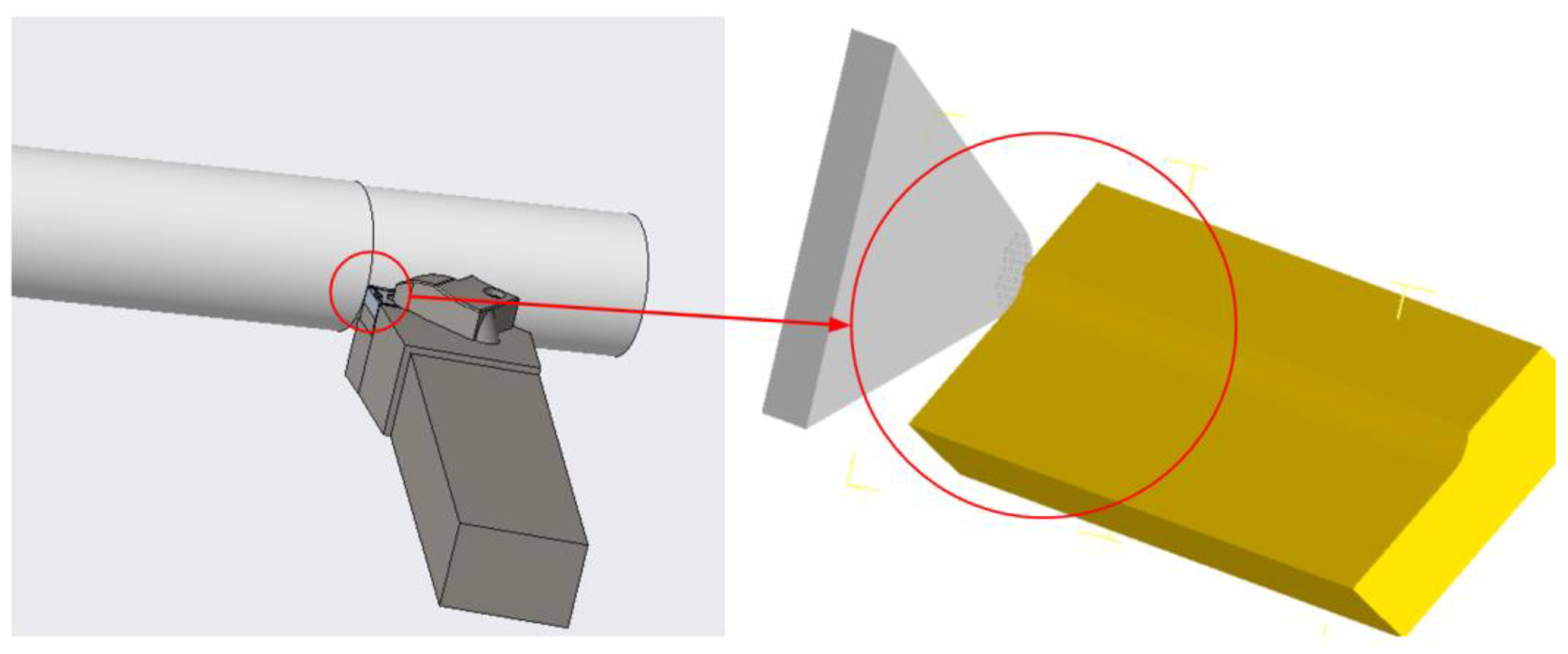
Figure 3.
Simulation Cloud Diagram of 14 Groups of Tool Wear.
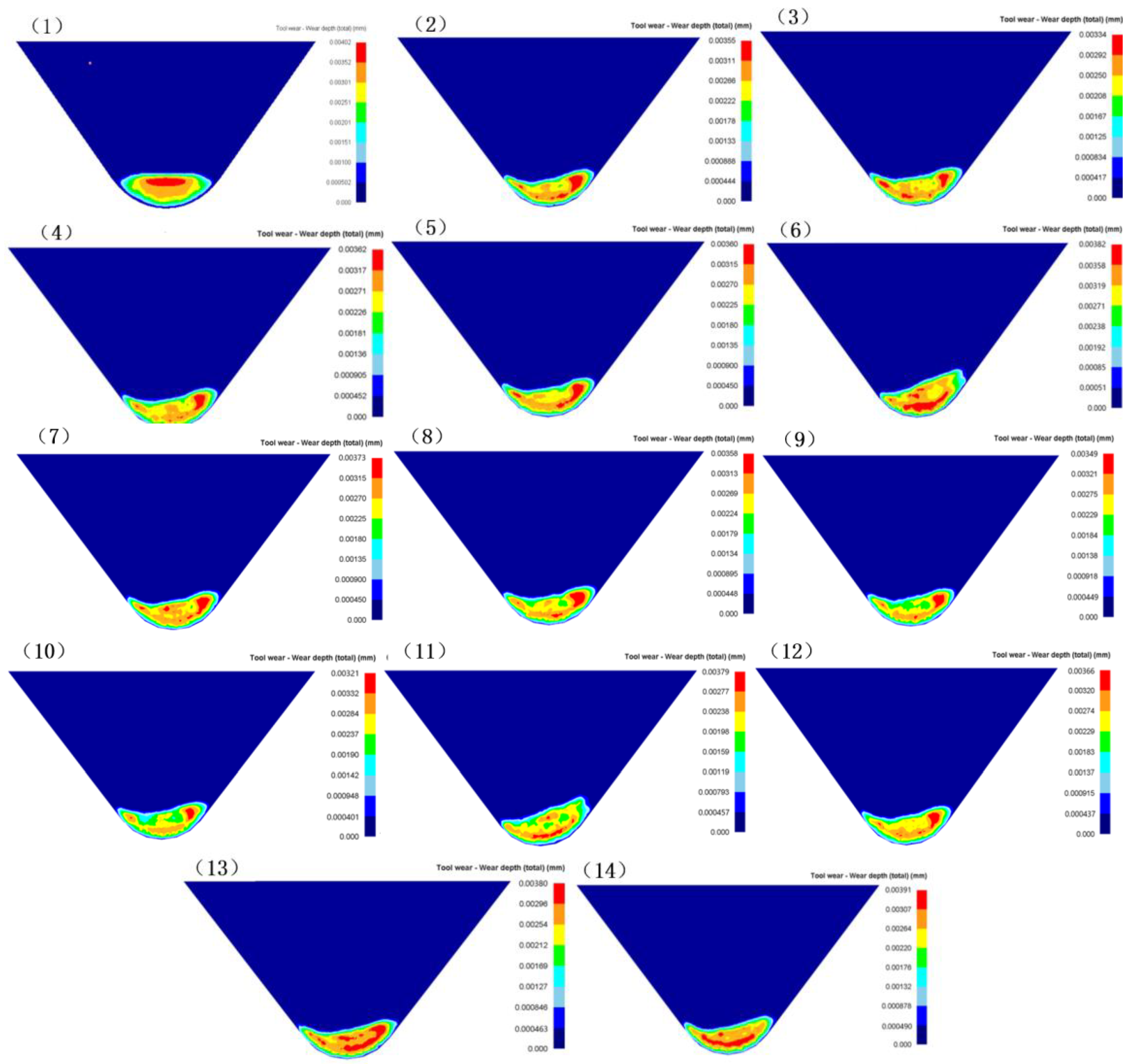
Figure 4.
Experiment setup: (a) spray cooling site; (b) spray cooling equipment.
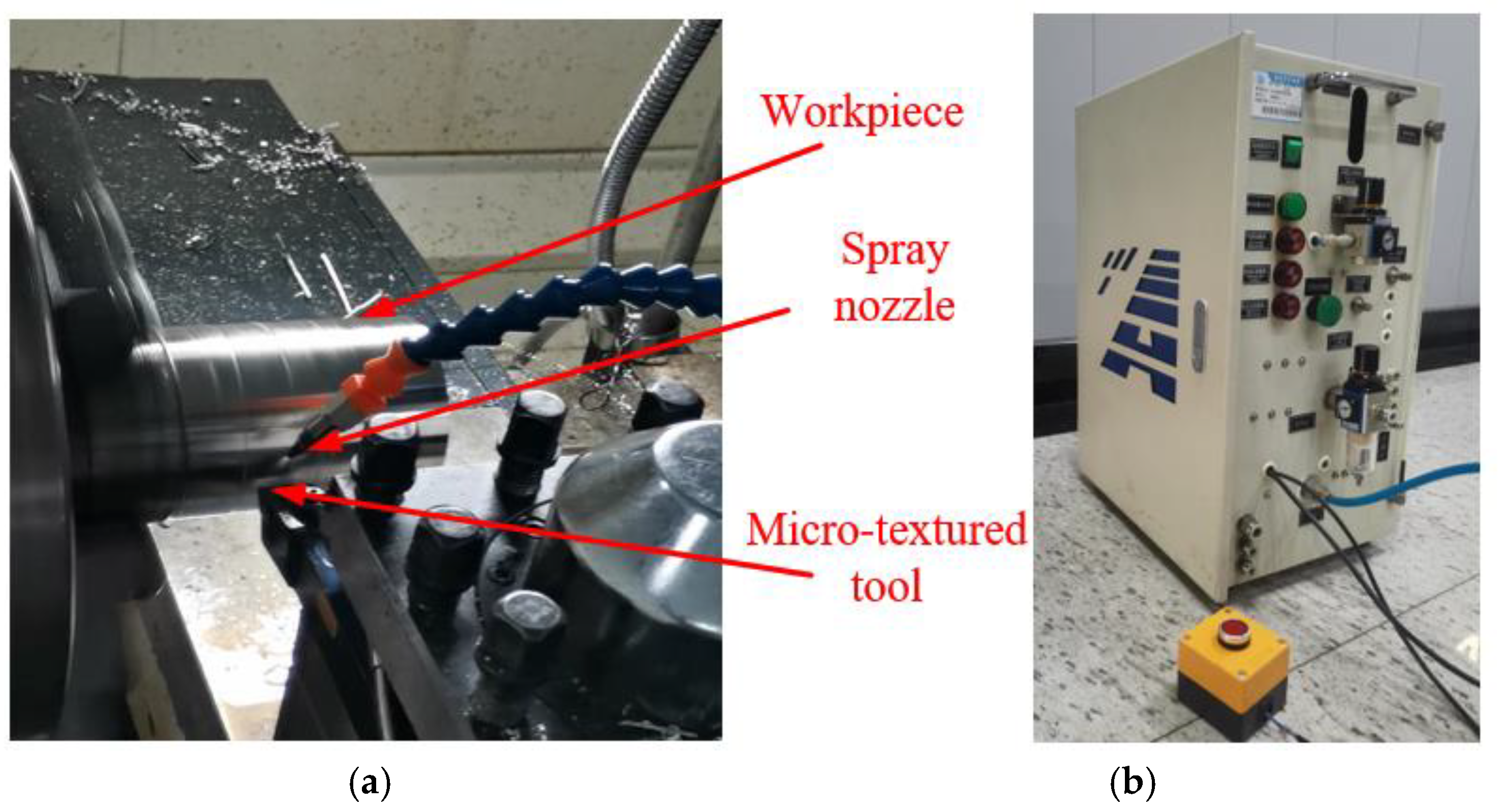
Figure 5.
Wear morphology on rake faces of 14 groups of tools.
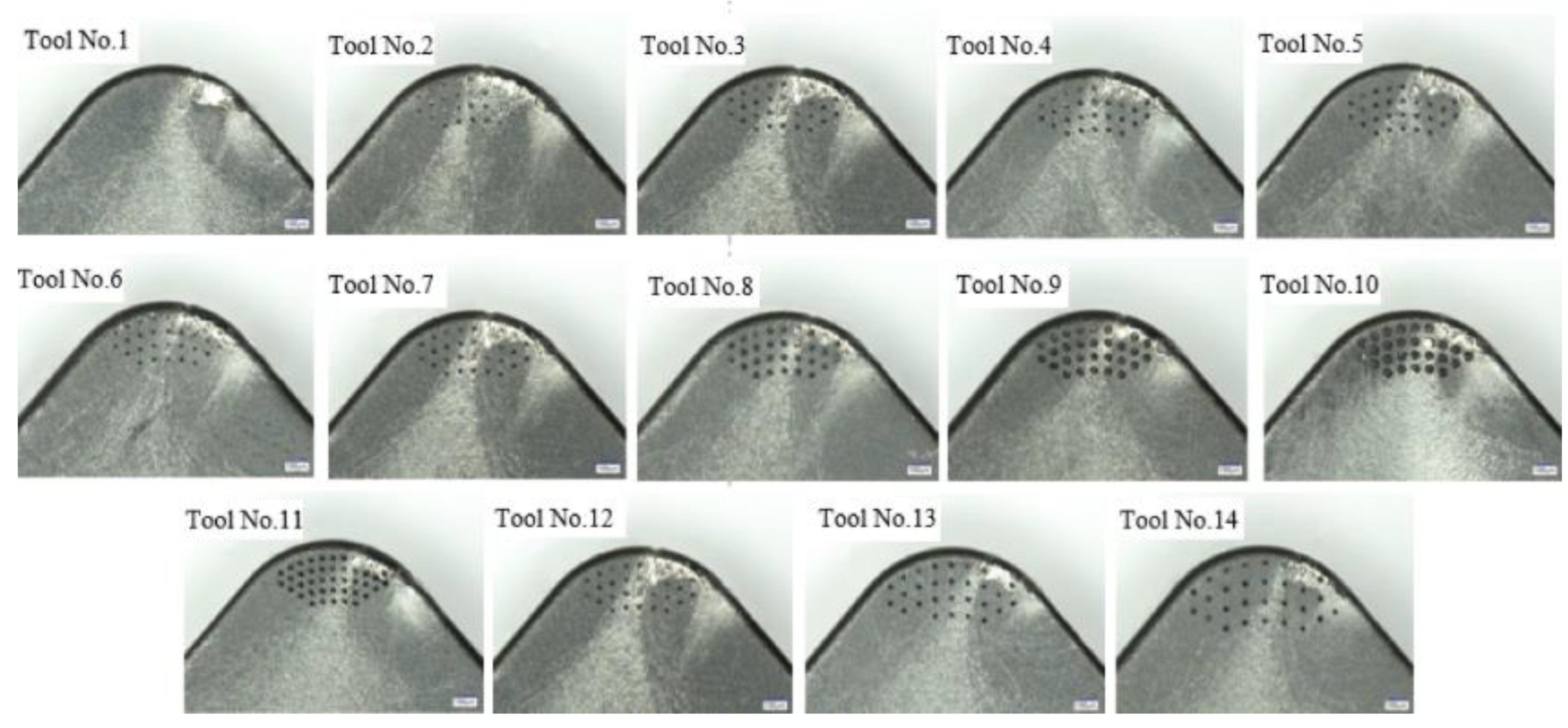
Figure 6.
Wear morphology and enlarged wear areas on the rake faceLa) Tool No.1;(b) Tool No.10.
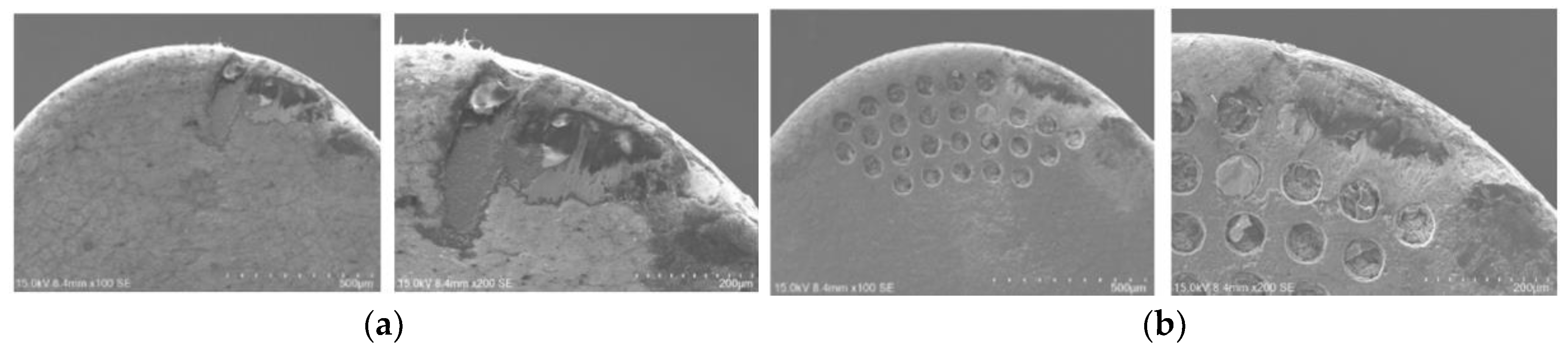
Figure 7.
Lubrication effect of micro-textured micro-pool.
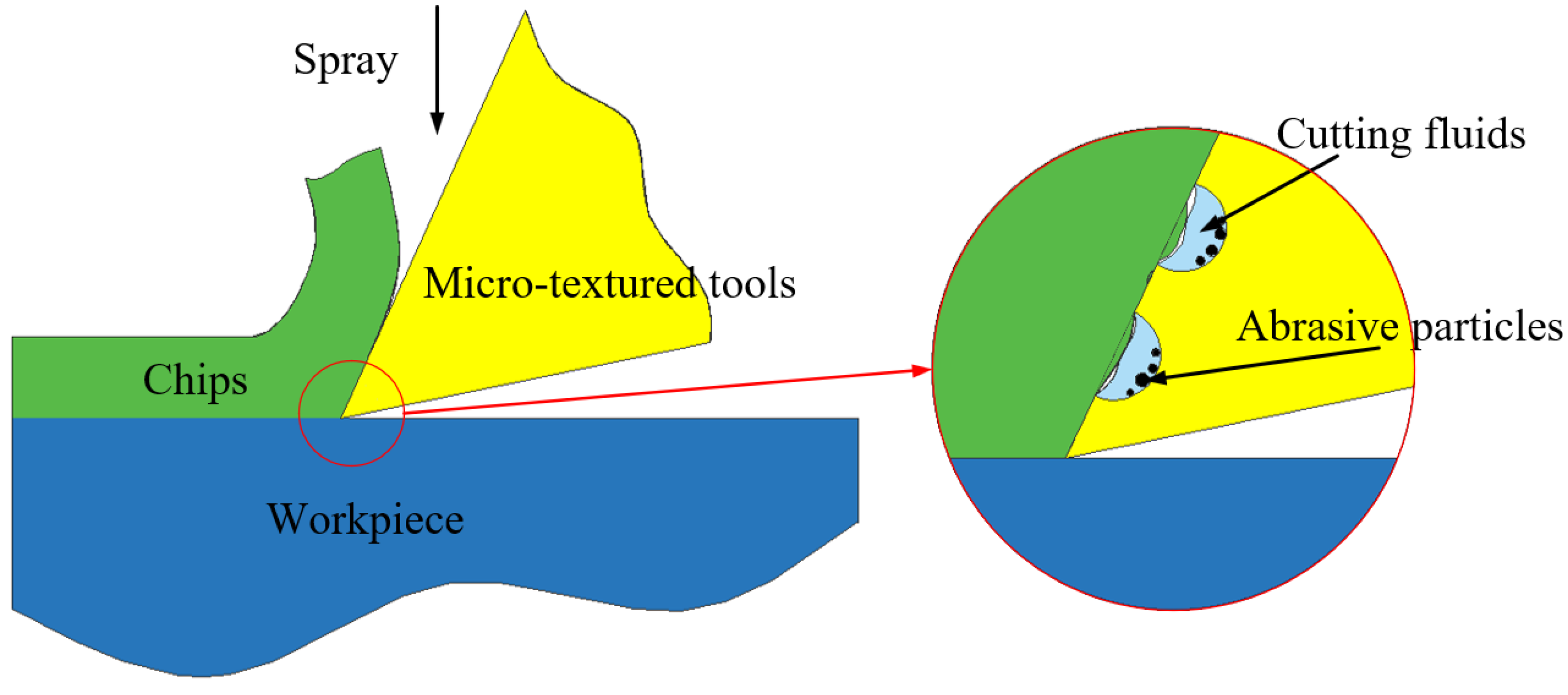
Figure 8.
Simulation results of hydrodynamic lubrication: (a) Simulation results of oil film surface pressure; (b) Streamline diagram inside the pit.
Figure 8.
Simulation results of hydrodynamic lubrication: (a) Simulation results of oil film surface pressure; (b) Streamline diagram inside the pit.
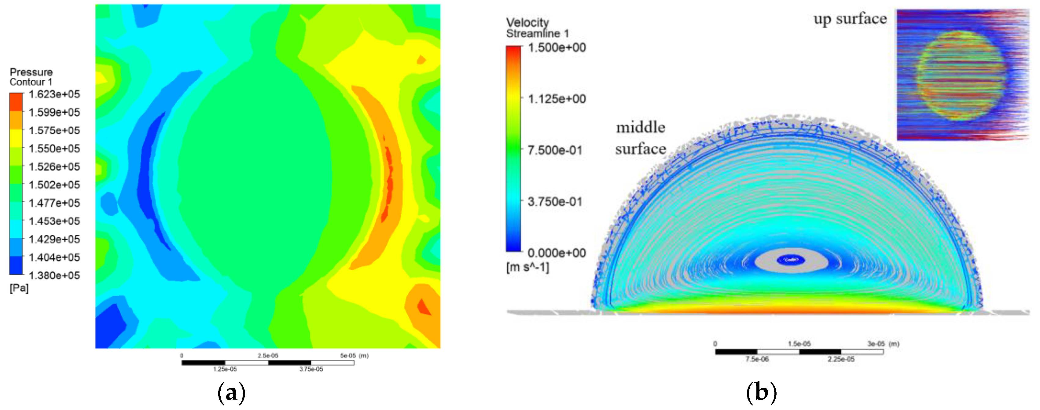

Table 1.
Combination scheme of the micro-pit parameters.
| Tool No. | A/μm | B/μm | C/μm |
|---|---|---|---|
| 1 | - | - | - |
| 2 | 40 | 40 | 100 |
| 3 | 60 | 40 | 100 |
| 4 | 80 | 40 | 100 |
| 5 | 100 | 40 | 100 |
| 6 | 60 | 30 | 100 |
| 7 | 60 | 40 | 100 |
| 8 | 60 | 50 | 100 |
| 9 | 60 | 60 | 100 |
| 10 | 60 | 70 | 100 |
| 11 | 60 | 40 | 80 |
| 12 | 60 | 40 | 100 |
| 13 | 60 | 40 | 120 |
| 14 | 60 | 40 | 140 |
Table 2.
Wear depth range of micro-pit textured tools (μm).
| Tool No. | Min. Wear Depth/μm | Max. Wear Depth/μm |
|---|---|---|
| 1 | 0.502 4.02 |
4.02 |
| 2 | 0.444 | 3.55 |
| 3 | 0.417 | 3.34 |
| 4 | 0.452 | 3.62 |
| 5 | 0.45 | 3.6 |
| 6 | 0.51 | 3.82 |
| 7 | 0.45 | 3.73 |
| 8 | 0.448 | 3.58 |
| 9 | 0.449 | 3.49 |
| 10 | 0.401 | 3.21 |
| 11 | 0.457 | 3.79 |
| 12 | 0.437 | 3.66 |
| 13 | 0.463 | 3.8 |
| 14 | 0.49 | 3.91 |
Table 3.
Calculation results of wear area on the rake face.
| Tool No. | Equivalent Bandwidth/μm | Equivalent BandLength/μm | Wear Area S/μm2 |
|---|---|---|---|
| 1 | 209 | 522 | 109098 |
| 2 | 162 | 649 | 105138 |
| 3 | 168 | 587 | 98616 |
| 4 | 159 | 615 | 97785 |
| 5 | 146 | 634 | 103976 |
| 6 | 178 | 533 | 94874 |
| 7 | 168 | 587 | 98616 |
| 8 | 141 | 530 | 74730 |
| 9 | 143 | 490 | 70070 |
| 10 | 151 | 461 | 69611 |
| 11 | 153 | 518 | 79254 |
| 12 | 168 | 587 | 98616 |
| 13 | 161 | 558 | 89838 |
| 14 | 173 | 561 | 97053 |
Disclaimer/Publisher’s Note: The statements, opinions and data contained in all publications are solely those of the individual author(s) and contributor(s) and not of MDPI and/or the editor(s). MDPI and/or the editor(s) disclaim responsibility for any injury to people or property resulting from any ideas, methods, instructions or products referred to in the content. |
© 2025 by the authors. Licensee MDPI, Basel, Switzerland. This article is an open access article distributed under the terms and conditions of the Creative Commons Attribution (CC BY) license (http://creativecommons.org/licenses/by/4.0/).
Copyright: This open access article is published under a Creative Commons CC BY 4.0 license, which permit the free download, distribution, and reuse, provided that the author and preprint are cited in any reuse.


