
Submitted:
11 October 2024
Posted:
15 October 2024
You are already at the latest version
Abstract
The increasing deployment of large-scale wind turbines in place of conventional generators is expected to lead to the dominance of asynchronous power sources in future power systems, further accelerating the trend toward grid electrification. As a result, the ability of power sources to support system voltage and frequency is gradually diminishing. Synchronous condensers (SC), which are synchronous machines operating without prime movers, serve as effective devices for providing both dynamic voltage support and inertia. They can significantly enhance the system’s capacity to maintain voltage and frequency stability. However, most existing studies on the optimization of synchronous condenser configurations tend to focus on only one aspect at a time, rather than addressing both simultaneously, limiting the full potential of these devices. Optimizing either voltage or frequency in isolation often results in suboptimal improvements in the other. Moreover, simultaneous optimization of both voltage and frequency can lead to non-convergent outcomes, complicating the search for an optimal solution. To address this, the paper proposes a hierarchical optimization strategy for synchronous condenser configuration aimed at enhancing both voltage and frequency stability. First, the configuration sites for the synchronous condensers are determined based on short-circuit ratio (SCR) constraints. Next, an outer layer optimization model is developed to minimize the total installed capacity of the condensers, while taking into account SCR and transient overvoltage levels as constraints. Following this, an inner layer optimization model is introduced, incorporating and as constraints. The model is solved using the bacterial foraging optimization algorithm (BFOA). Finally, a case study of a power grid with a high proportion of wind power validates the effectiveness of the proposed synchronous condenser configuration strategy. Compared to traditional methods, the total required capacity of synchronous condensers was significantly reduced.
Keywords:
SCR
; Transient overvoltage
; Frequency stability
; High percentage of wind power
1. Introduction
The integration of large-scale wind power units into the sending-end power grid, along with the replacement and phase-out of conventional synchronous units, has significantly increased the contribution of renewable energy to electricity supply. However, this transition has weakened system voltage strength and inertia support, posing severe challenges to voltage and frequency stability [1,2,3]. On one hand, replacing traditional power plants with renewable energy sources will significantly reduce the system's short-circuit ratio (SCR), thereby weakening its voltage support capabilities [4,5]. The control structure of wind turbine units inherently includes time-delay characteristics in both the inertia and proportional-integral components, and the reactive power generation of wind turbines displays hysteresis behavior. After a fault is cleared, an excess of reactive power may occur briefly, causing a transient overvoltage issue that impacts the safe and stable operation of grid-connected units [6,7]. On the other hand, the weak inertia support in high-renewable energy power systems is making system frequency stability an increasingly prominent issue [8,9].
Synchronous condensers (SC), which are synchronous machines operating without prime movers, act as efficient devices for providing dynamic voltage support and inertia. They can significantly enhance the system's ability to maintain both voltage and frequency stability. The effect of connecting SC on boosting the short-circuit strength of the power system, Literature [10] proposes a method for the optimal configuration of SCs in a hypothetical future scenario involving a transmission system powered by renewable energy generation. The SCR of renewable energy at the wind turbine point of interconnection (POI) is improved. However, the method does not provide a way to determine the required capacity of the SC. Literature [11] proposed a method for the optimal configuration of SCs to improve the SCR of buses at converter stations using an enhanced short-circuit analysis method. However, the capacity optimization of the SCs was not performed. The suppression of transient overvoltages through reactive power compensation configurations in power grids has been explored in the literature. Literature [12] focuses on large-scale wind and photovoltaic power connected to the DC transmission system, using simulation analysis to assess the ability of distributed SCs at new energy sites to suppress transient overvoltages. However, no specific method for determining the siting and capacity of the SCs was proposed. Literature [13] proposed an optimal allocation scheme for SC in the new energy sending-end system, based on a transient voltage rise severity index to mitigate transient overvoltage issues. However, it did not fully account for the transient overvoltage safety standards for new energy units. Literature [14] proposes an optimal allocation method for SC, using the voltage ride-through capability of new energy units as a constraint to enhance the transient voltage support of wind farms at the delivery end of the grid. Literature [15] investigated the transient voltage support capabilities of three types of reactive power compensation devices—SVC, STATCOM, and SC—for the sending-end grid and provided a recommended reactive power compensation scheme to improve the voltage security of the sending-end grid. However, it did not address a specific optimal allocation method for reactive power compensation. Literature [16] proposes a two-stage optimal configuration strategy for SC, considering both the short-circuit ratio and transient overvoltage suppression. However, it fails to address the role of SC in enhancing system inertia and strengthening frequency support. To enhance the system's dynamic frequency response in terms of inertial support provided by the SC, Literature [17] investigated the principle of SC's inertial response and its role in enhancing frequency stability but did not propose an efficient or feasible strategy for site selection and capacity determination. Literature [18] proposes an energy storage siting and capacity determination method that enhances the frequency support capability, but it does not consider the SC, which is currently becoming a research hotspot. The aforementioned studies focus on optimizing SCs for voltage stability and system frequency stability independently, but they lack an effective integration of both optimization approaches.
In summary, existing studies often focus on optimizing either voltage support or inertia enhancement, but rarely address both simultaneously. Although SCs are efficient devices for providing both voltage and inertia support, their full potential has yet to be realized. Optimizing voltage or frequency in isolation can lead to suboptimal outcomes, while simultaneous optimization of both may result in non-convergent solutions. To address the limitations and challenges of previous research, this paper focuses on power grids with high wind power penetration and proposes a hierarchical optimization strategy for SC configuration. The objective is to leverage SCs to enhance voltage stability at wind turbine Points of Interconnection (POIs) while also improving frequency stability during the system’s inertia response phase. This study first analyzes the impact of synchronous condenser (SC) connection on short-circuit ratio (SCR), transient overvoltage, and frequency stability during the inertia response phase. Following this, a hierarchical optimization strategy for SC configuration is introduced, aiming to suppress transient overvoltage, enhance SCR at wind turbine POIs, and improve system frequency stability. This strategy is further optimized using the bacterial foraging optimization algorithm (BFOA). During the siting phase, SCR enhancement and transient overvoltage suppression serve as primary constraints in the outer layer optimization, which helps preliminarily determine the optimal configuration locations and capacity configurations of the SCs. Once these key constraints are satisfied, the main constraint conditions for the optimization of the system's inertia within the inner layer, defined by frequency stability constraints, are optimized again for the capacity configuration of the synchronous condensers. Finally, a case study of a power grid with high wind power penetration verifies the effectiveness of the proposed SC configuration strategy. Compared to traditional methods, the proposed approach significantly reduces the total required capacity of SCs.
2. The Impact of Synchronous Condenser Configuration on Both Voltage and Frequency Stability
2.1. The Impact of Synchronous Condenser Configuration on the Short-Circuit Capacity at the Wind Turbine POI
The short-circuit capacity at a point in the grid is the product of the three-phase short-circuit current at that point and the rated voltage, i.e., equation (1)
Short-circuit capacity is a crucial indicator of the strength of grid voltage support. High short-circuit capacity (corresponding to low impedance) indicates grid robustness, meaning that load variations or the connection of shunt filters do not cause significant voltage fluctuations. Conversely, low short-circuit capacity indicates increased grid vulnerability, where load changes or the connection of shunt filters may lead to substantial voltage fluctuations.
Given that the SC is connected to the grid through the stator resistor, it can be regarded as a shunt inductive branch in the grid. For the circuit shown in Figure 1, Let its network transfer impedance equivalent to positive sequence reactance be , the equivalent impedance between the SC connect point and the short-circuit point is positive sequence equivalent reactance , the positive sequence reactance of the SC is , the system equivalent power supply is .
From equation (1), short-circuit current directly affects short-circuit capacity. Therefore, the effect of SC connection on short-circuit current is analyzed first. In the event of a short-circuit fault before the SC is connected, the per unit (p.u.) value is used for calculation. The short-circuit current flowing at the short-circuit current is
After connecting to the SC, the short-circuit current flowing at the short-circuit point changes to
Considering that both line and SC stator windings are inductive, thus there is, i.e. . It can be seen that connecting to the SC increases the short circuit current and, subsequently, the short circuit capacity.
2.2. Evaluation Index for Grid Voltage Support Strength
The model of the SC connected to the grid is shown in Figure 2. The SCR is given by equation (4), Used to ensure that the wind turbine POI is of adequate strength [19], and can be used to characterize the support strength of the grid voltage.
In the equation, is the short-circuit capacity of bus , is the nominal active power of the wind turbine installed at busbar , is the Thevenin's equivalent impedance. The SCR can be equivalently expressed in equation (5) when the rated bus voltages and are taken as the reference values, It can be seen that the larger the SCR, the smaller the Thevenin's equivalent impedance is, and a disturbance in the system will not cause a significant change in voltage magnitude.
The results of short-circuit power calculations vary depending on the method used. In this paper, short-circuit calculations are performed according to the IEC 60909 standard, which is widely applied in grid planning.
IEC 60909 defines maximum and minimum values for short-circuit power, which are calculated using different network configurations. In this paper, these two configurations are reconciled by taking the average of the maximum and minimum short-circuit power, as expressed in equation (6).
In the equation, is the maximum short-circuit capacity of bus , is the minimum short circuit capacity of bus , is the average of the maximum and minimum short circuit capacity. Combining equation. (4) with equation. (6), the SCR can be expressed by equation (7).
2.3. The Effect of Synchronous Condenser Connection on Transient Overvoltage at the Wind Turbine POI
1) Transient overvoltage levels in the wind farm before and after synchronous condenser connection.
In the modified arithmetic example (presented in Section 4), Bus 25 experiences a three-phase short-circuit fault lasting 0.1 seconds. Before and after the connection of wind turbine POI buses Bus 25, Bus 29, and Bus 39 to the 50 MVA SC, the changes in voltage at the wind turbine POI of DFIG39, the output reactive power, and the SC's reactive power are shown in Figure 2.
Before the SC is connected, during a fault, the voltage at Bus 39 drops, and the connected DFIG39 wind turbine increases its reactive power output. Due to the hysteresis characteristic of the wind turbine's reactive power response, the voltage recovers instantaneously after the fault is cleared. However, because of the time-delay characteristic of the control system, the additional reactive power generated during the fault cannot be withdrawn, resulting in excess reactive power and transient overvoltage at the machine terminal. Simulation results show that the maximum transient overvoltage reaches 1.452 p.u.
After the SC is connected, its synchronous rotating nature and electromagnetic transient characteristics help maintain magnetic flux in the windings before and after fault disturbances, making the reactive power response instantaneous. At the moment of the fault, the voltage drops, and the SC immediately increases its reactive power output to mitigate the voltage drop. Once the fault is cleared, the voltage recovers, and the SC quickly reduces its reactive power and absorbs the excess reactive power, effectively suppressing transient overvoltage. The maximum voltage is reduced to 1.333 p.u. The electromagnetic transient characteristics of the SC windings contribute to suppressing the transient overvoltage level after the fault is cleared.
2) The Mechanism of Transient Overvoltage Suppression by Synchronous Condenser Connection
SCs are connected to the wind farm via transformers and serve as reactive power compensation devices, with their active power being minimal and negligible. Based on the active power expression for generators, when the power angle , the high-voltage side voltage of the synchronous condenser transformer and the injected reactive power can be expressed as follows:
In the equation, , , represent the high-voltage side voltage of the SC, the direct axis voltage component, and the quadrature axis voltage component, respectively. and represent the direct axis and quadrature axis current components, respectively, while denotes the reactive power injected by the SC.
The change in reactive power output of the SC before and after a disturbance can be expressed in incremental form as:
In the formula, the subscript 0 represents the electrical quantity before the disturbance, and the symbol represents the change in the electrical quantity.
The change in before and after the disturbance is very large, which has a significant impact on the reactive power change of the SC. The following derivation is combined with the SC model.
Based on the -axis transient and subtransient differential equations related to in the six-order model of the synchronous machine, and the algebraic equation of the internal voltage and terminal voltage, when ignoring the stator resistance, the following expressions can be derived:
In the formula, , , and represent the synchronous reactance, transient reactance, and subtransient reactance of the -axis for the SC, respectively. and represent the transient and subtransient open-circuit time constants of the -axis for the SC, respectively. , and represent the field excitation voltage, -axis transient voltage, and -axis subtransient voltage of the SC, respectively. and represent the derivatives of and , respectively, and represents the reactance of the transformer at the output of the SC.
The expressions for and are:
In the formula, and represent the magnetic fluxes of the field winding and the damper winding , respectively. , , and represent the direct-axis armature reaction reactance, the leakage reactance of the winding, and the leakage reactance of the winding, respectively.
Expressing equation (10) in incremental form and applying the Laplace transform, we get:
In the equation, , , and represent the changes in the corresponding voltages, and is the Laplace operator.
From the first equation of (13), we can solve for , which is:
In the above equation, is expressed as the difference between the change in the subtransient -axis internal voltage and the change in the high-voltage side terminal voltage of the SC, divided by the reactance . can be derived from equation (13) as follows:
In the equation, the coefficients , , , , and are, respectively:
Combining equations (14) and (15) allows us to express the time response characteristics of after the fault disturbance. At the instant of disturbance, due to the conservation nature of the winding magnetic flux, equation (12) indicates that cannot change abruptly, so in the instant of disturbance, . At this moment, equation (14) can be expressed as:
Substituting into equation (10), the instantaneous change in reactive power of the SC after the disturbance is:
From the first term of the above formula, it can be seen that since , the SC has a strong instantaneous reactive power support capability. The corresponding reactive power response is in the same direction as . Therefore, during the transient overvoltage phase after the fault is cleared, it will absorb a large amount of reactive power to suppress the transient voltage rise. The second term is usually much smaller than the first term (the change in current is greater than the pre-disturbance . When the pre-disturbance is smaller or negative (the synchronous condenser is operating in the leading power factor mode), the reactive power support capability for voltage is stronger, which is more favorable for suppressing the transient overvoltage after the fault is cleared.
2.4. The Impact of Synchronous Condenser Connection on Frequency Stability during the System Inertia Response Phase
The frequency of a power system is collectively determined by the rotational speeds of the numerous synchronous machines within it. When a disturbance occurs in the system, due to the rotational inertia and conservation of magnetic flux in the rotor windings of synchronous machines, the magnitude and phase of the equivalent electromotive force (EMF) of these machines, including SCs, do not change abruptly. This characteristic ensures that when a disturbance occurs, such as a sudden increase in load causing an active power imbalance in the receiving-end system, the power deficit is automatically transmitted and distributed to synchronous machines with voltage source characteristics, in proportion to the inverse of the electrical distance from the disturbance point to each machine. As a result, the output electromagnetic power (corresponding to the resistive torque acting on the rotor shaft) of the synchronous machines increases rapidly. At this point, the prime mover power (corresponding to the motive torque acting on the rotor shaft) has not yet changed. According to the rotor motion equation of the synchronous machine (as shown in equation (19)), the speed of the synchronous machine will decrease. This process is referred to as the inertial response of the synchronous machine.
In the equation is the unit electrical speed or system frequency, is the rated electrical speed of the unit or the rated frequency of the system; is the unit inertia time constant or the system equivalent inertia time constant; is the prime mover power; is the output electromagnetic power of the synchronous machine.
Synchronous condensers, as a type of synchronous machine, adhere to the conservation of magnetic flux and possess an inertial response, similar to synchronous generators. This means that SCs, like synchronous generators, exhibit the characteristics of a voltage source, where the magnitude and phase do not change abruptly. This characteristic ensures that part of the power deficit in the system will be transmitted to the SC through the electrical network in a timely manner. For SCs, the prime mover power in equation (19) is zero; if friction losses during operation are neglected, the electromagnetic power is also zero in the steady state. However, during the transient process of grid disturbances, SCs, like synchronous generators, will share the power disturbance, meaning . Due to the inherent inertia of their rotating elements, SCs take on a share of the system's power disturbance.
When a power deficit disturbance occurs in the system, both SCs and generators will increase their electromagnetic power output, leading to a decrease in their rotational speeds. Due to the effect of the generator set's prime mover governor system, or the primary frequency regulation effect, the generator's rotational speed will decrease to a certain extent (after passing the dead zone), after which the prime mover power will increase, slowing the speed decrease or even causing the speed to rise. SCs, however, do not have a prime mover system and lack primary frequency regulation capability. Therefore, over time, the rotational speed of the SC will become lower than that of the generator, causing the phase of the generator's potential to gradually lead to that of the condenser. According to the characteristics of the electrical network, active power flows from the leading phase to the lagging phase. As a result, over time, the electromagnetic power output by the SC will decrease, automatically transferring to the generator and eventually being fully borne by the generator. Ignoring friction losses, the electromagnetic power output by the SC will return to zero in the steady state. The impact of the condenser's connection on system frequency is shown in Figure 4. In summary, the inertial response of the SC increases the overall inertia of the system. Although it does not affect the steady-state frequency of the system after the disturbance, it influences the frequency dynamics following the disturbance. In conjunction with the system's primary frequency regulation, it delays the occurrence of the lowest frequency to some extent. When the power deficit is large and the primary frequency regulation capacity has not yet been adjusted, it prevents the system frequency from temporarily dropping to the first threshold of under frequency load shedding.
The magnitude of inertia in a power system is commonly quantified by the inertia time constant. The inertia of the entire power system can be defined as the sum of the rotational energies stored in all the rotating machines connected to the network, as shown in Equation (20).
In the equation is the rated capacity (MVA) of the synchronous generator, is the inertia time constant of the synchronous generator (s).
Calculate the center of inertia frequency as in equation (22) and its rate of change as in equation (23) from the output results.
In the equation is the synchronous machine end frequency
It is evident that the connection of renewable energy sources, which replace traditional synchronous generating units, leads to a decrease in the inertia level of the power system. By configuring SCs, the equivalent inertia of the system can be increased, which reduces the rate of frequency change and the maximum frequency deviation during the system's inertia response phase. This also delays the occurrence of the lowest frequency point, which is beneficial for improving the system's frequency dynamic response and promoting the stable operation of the power system.
3. Hierarchical Optimization Configuration of Synchronous Condensers Considering Voltage and Frequency Stability
This paper proposes a hierarchical optimization configuration method for SCs that simultaneously enhances voltage stability and system frequency stability. The aim is to address the issue of non-convergent optimization results when optimizing both. The configuration method is divided into two layers: first, the connection location of the SC is determined based on the SCR constraints at the wind turbine POIs; second, once the connection location is established, the outer layer optimization is performed with the primary constraints of enhancing SCR and suppressing transient overvoltage, to preliminarily configure the SC capacity. The inner layer optimization focuses on improving the system's minimum inertia, defined by the frequency stability index, and the Bacterial Foraging Optimization Algorithm (BFOA) is introduced to solve this. The overall structure of the current SC optimization configuration is shown in Figure 5.
3.1. Outer Layer Optimization Configuration of the Synchronous Condenser
3.1.1. Construction of the Optimal Configuration Model for the Outer Layer of Synchronous Condensers
The optimization model for the outer layer of SC configuration is established with the goal of minimizing SC capacity, taking into account constraints such as SCR at the wind turbine POI, transient overvoltage, synchronous condenser configuration capacity, and power flow. According to the national standard "Technical Specifications for Connecting Wind Farms to Power Systems" (GB/T 19963.1-2021), the wind farm's transient overvoltage level should not exceed 1.3 p.u. within 0.5 seconds after fault clearance. The model is represented as follows:
In the equation, is the number of wind farms that need to be connected to SC, is the capacity of the SC configured at the wind farm, denotes the penalty factor that considers the SCR and transient overvoltage safety.
Restrictive condition:
- Sending-end grid wind turbine POIs short-circuit ratio constraints:
- 2.
- Overvoltage safety constraints during transient processes:
In the equation, is the SCR of the wind turbine POIs, is the transient peak voltage at the wind turbine POI under time domain simulation, if in all failure scenarios, When the wind turbine POIs all meet the SCR and transient overvoltage safety requirements, is 0; otherwise, takes the value of a positive infinity number.
- 3.
- Wind turbine POI i configuration SC capacity constraints:
In the equation, is the capacity of the single SC connected to the wind farm.
- 4.
- Steady-state tidal current constraint:
In the equation, and denote the active and reactive power at node i respectively, and are the voltages at nodes and , and are the real and imaginary parts of the position of the node conduction matrix (, ), denotes the phase difference between the th and th nodes.
3.1.2. Model Solution for Optimal Configuration of the Outer Layer of the Synchronous Condenser
For the optimized configuration model established above, the specific solution steps are shown in conjunction with the process in Figure 5:
- Considering the model parameters of the sending-end power grid components and the power flow operation status, an electrical grid model with a high proportion of wind power is established;
- Calculation of SCRs at the wind turbine POI in the grid under normal sending-end grid currents;
- The SCR does not satisfy the constraints at the optimal location for the SC configuration, so an SC with a base capacity of 50 MVA is placed.
- Solving the model using a bacterial foraging algorithm for the initial configuration of SC capacity;
- Three-phase short-circuit fault scanning of the sending-end wind turbine POIs connected to SCs;
- Recalculate the SCR of the sending-end wind turbine POIs connected to the SC and observe the voltage trajectories of the different wind turbine POIs for each fault scenario;
- Determine whether the current configuration satisfies the SCR constraints and transient overvoltage safety constraints for all fault scenarios. If so, complete the optimal configuration of the SC; otherwise, return to step 4.
3.2. Optimized Configuration of the Inner Layer of the Synchronous Condenser
Considering voltage stability, the outer layer optimization configuration of the SC effectively enhances the voltage support capability of the wind farm in the sending-end power grid and improves the transient overvoltage safety of the wind farm after a disturbance. However, it remains difficult to ensure the system's frequency security, and stability after a disturbance. Therefore, further optimization of system frequency stability is conducted, and an inner layer optimization configuration method for the SC is proposed, taking into account constraints such as the rate of frequency change and the maximum frequency deviation at the system inertia center. The SC capacity configuration is optimized again, and the corresponding optimization model and solution method are as follows.
3.2.1. Construction of the Optimal Configuration Model for the Inner Layer of Synchronous Condensers
The objective function is equation (24). Also, consider and based on critical inertia constraints and SC configuration capacity size constraints, to model the optimal SC configuration, the model is represented as follows:
Constraints:
- The expression for the minimum inertia constraint of the system is based on the constraint is given by:
In the equation, is the maximum value of disturbance power.
The implication is that in order for the rate of change of the frequency of the centre of inertia not to exceed the threshold when the maximum value of perturbation power occurs in the system, the system inertia should be greater than .
- 2.
- The expression for the minimum inertia constraint of the system based on the -constraint is derived from the literature [20] based on the frequency response model of the multi-machine system, and the expression is given as:
In the equation, is the base frequency; is the moment when the lowest point of the frequency occurs.
3.2.2. Model Solution for Optimal Configuration of the Inner Layer of the Synchronous Condenser
For the optimal configuration model established above, the combination process is shown in Figure 5, and its specific solution process is as follows:
- Obtain the capacity and inertia time constant of the synchronous condenser units in the system, and set the inertia time constant of the SC to 7.84 seconds, representing a high-inertia condenser;
- Calculation of the critical inertia indicators and of the system for determining the frequency stability;
- The model was further solved using the BFOA to reconfigure the SC capacity;
- Calculate the system inertia and based on the rate of frequency change of the center of inertia and the maximum magnitude of the frequency change;
- Determine whether the current configuration satisfies , . If it does, the current SC capacity configuration is feasible; otherwise, return to step 3.
In the present study, we have harnessed the bacterial foraging optimization algorithm, as delineated in references [21,22], to address the formulated optimization model, thereby culminating in the derivation of the optimal SC configuration. Bacterial foraging algorithms are an innovative class of bio-inspired algorithms, modeled on the behavior of Escherichia coli as they consume nutrients in the human gut. This algorithm has emerged as a prominent focus in the research field of bio-heuristic computation, thanks to its ability to perform parallel searches characteristic of swarm intelligence algorithms, and its capacity to effectively escape local minima. In the bacterial foraging optimization algorithm (BFOA) model, the space vector ( is the vector dimension) is treated as a bacterium. The solution of the optimization problem corresponds to the health state of the bacterium in the search space; that is, the optimization function adapts the value. The BFOA consists of three key steps: chemotaxis, reproduction, and dispersal:
- Chemotaxis: The behavior of bacterial aggregation toward nutrient-rich regions. During chemotaxis, bacterial movement patterns involve flipping and advancing. A bacterium changing direction to move a unit step is called a flip. After a flip, if the adaptation value improves, the bacterium continues to move in the same direction for several steps until the adaptation value stops improving or a predetermined threshold of steps is reached. This process is referred to as advancing. The chemotaxis process can be expressed by the following equation:
In the equation, is the dispersion, reproduction, Space vector of the bacterium in the th chemotaxis process; is the length vector of bacteria moving in a certain direction; is the unit direction vector,; In the process of convergence, Bacteria are subject to a combination of attraction and repulsion, which the following equation can express:
is the value of the objective function; are the attraction and repulsion coefficients.
- Reproduction: After the life cycle ends, i.e., when a critical number of chemotaxis steps has been reached, the bacteria undergo reproduction. This process follows the natural principle of 'survival of the fittest.
In the equation, is the number of chemotaxis. The worse half of the bacteria died, and the better half split into two daughter bacteria, as measured by the cumulative sum of the adaptation values for each bacterium during chemotaxis. The daughter bacteria will inherit the biological characteristics of the parent bacteria, having the same position and step length as the parent bacteria.
- Dispersal: The chemotaxis process ensures the bacteria’s local search capability, while the reproduction process accelerates the search. However, for complex optimization problems, chemotaxis and reproduction alone cannot prevent bacteria from becoming trapped in local optima. BFOA incorporates a dispersal process to enhance the algorithm’s global optimization search capability. After completing a certain number of reproduction cycles, the bacteria are dispersed to random locations within the search space with a certain probability. In this paper, the bacterial foraging optimization algorithm is applied to the problem of optimal configuration of a SC. The number of connected SCs is used as the bacterial variable, and the BFOA must be applied with the condition that all variables are integers. The space vector , consisting of the SCs connected to the wind farms, is treated as a bacterium. The total capacity of the SC, calculated using equation (24), represents the health state of the bacterium in the search space, which corresponds to the fitness value in the optimization process.
In the BFOA algorithm, the bacterial entities are represented as N-dimensional spatial vectors, with the dimensionality determined by the number of interconnected SCs. The algorithm specifies a population size of 20 bacteria per generation, with each bacterium executing 5 chemotactic steps. The reproduction phase involves 2 bacteria, while the maximum number of forward steps is capped at 4. The step size is set to 25 units. Furthermore, the algorithm accounts for a 0.5 probability of bacterial demise during the reproduction phase and a 0.25 probability of dispersal.
4. Case Studies
The proposed method is initially validated using a modified 39-bus system. As shown in Figure 6, all synchronous machines in the system, except for G2, G3, and G5, are replaced with doubly-fed induction generator (DFIG) wind turbines of equivalent output. Wind power contributes 68.16 percent of the total power output. According to the literature [13], the SCR requirements for wind turbine POIs must exceed 3. Additionally, per the national standard GB/T 19963.1-2021, the transient overvoltage of the wind turbine following a fault must remain below 1.3 p.u. The maximum allowable frequency deviation for the system is set to = 0.8 Hz and the maximum rate of change of frequency is = 0.1 Hz/s. The critical inertia, based on the maximum frequency deviation, is determined by the time at which the lowest point in the frequency data occurs during each SC capacity optimization process. In response to these requirements, SC configurations for wind farms in the sending-end grid are implemented. The effectiveness of the proposed SC configuration strategy is validated through the development of a Python-DIgSILENT interconnected simulation platform.
4.1. SCRs and Transient Overvoltage Levels at the Wind Turbine POIs in the Sending-End Grid before and after Configuration of Synchronous Condensers
The SCR levels at the POIs before connecting the SC are presented in Table 1. The wind turbines that do not meet the SCR constraints include DFIG25, DFIG29, and DFIG39. A three-phase short-circuit fault with a duration of 0.1 seconds is applied at each wind turbine POI. The transient overvoltage scenarios at the wind turbine POIs after fault clearance are presented in Table 2. The transient overvoltage trajectories for the wind turbine POI buses—Bus25, Bus29, and Bus39—which do not satisfy the SCR constraints in the aforementioned fault scenarios, are shown in Figure 7.
The data above indicate that the short-circuit ratio and transient overvoltage levels at certain wind turbine POIs do not meet the requirements in the absence of SC configuration.
An SC with a capacity of 50 MVA is configured at each of the aforementioned wind turbine POIs that do not meet the SCR requirements. The short-circuit ratios and transient overvoltage levels at the wind turbine POIs after the SC connection are presented in Table 3 and Table 4.
The SCR level at each wind turbine POI improved after the SC was connected. Three-phase short-circuit faults with a duration of 0.1 seconds were applied at each POI. The voltage traces at the POIs connected to an SC with a capacity of 50 MVA are shown in Figure 8. The transient overvoltage in each fault scenario occurs at the DFIG39 wind turbine POI. The voltage peaks exceed 1.3 p.u., which does not meet the requirements for the safe and stable operation of wind turbines on the grid. The next step involves SC capacity optimization.
4.2. Short-Circuit Ratio and Transient Overvoltage Level at the Wind Turbine POI after the Optimized Configuration of the Outer Layer of Synchronous Condensers
The optimal configuration of the SC connected to the grid is carried out according to Section 3.1, and the configuration process is illustrated in Figure 5. SC capacity configurations range from 50 MVA to 300 MVA, and the SCR at each wind turbine POI exceeds 3. The maximum transient overvoltage after fault clearance is less than 1.3 p.u. Based on the SC optimization process outlined in Section 3.1.2, the configuration results in the configuration of an SC (50 MVA) at the DFIG25 wind turbine POI, an SC (225 MVA) at the DFIG29 wind turbine POI, and an SC (225 MVA) at the DFIG39 wind turbine POI. After the optimized configuration of the outer layer of the SC, the individual wind turbine POI SCRs are presented in Table 5. At this point, the SCR at all POIs exceeds 3, with a minimum SCR of 3.05. The voltage traces for the fault scenarios are shown in Figure 9, with the maximum transient overvoltage at Bus39 recorded at 1.267 p.u. While meeting the transient overvoltage suppression requirements, the SCR at the POI on the delivery end of the grid is further improved. However, the frequency safety and stability of the system after disturbances have not yet been considered, and further attention must be given to SC capacity configuration.

Table 5.
SCR levels of wind turbines POI after the outer layer optimized configuration of the synchronous condenser.
Table 5.
SCR levels of wind turbines POI after the outer layer optimized configuration of the synchronous condenser.
| wind turbine | SCR | wind turbine | SCR |
|---|---|---|---|
| DFIG2 | 14.95 | DFIG22 | 4.48 |
| DFIG39 | 3.05 | DFIG23 | 4.02 |
| DFIG19 | 6.80 | DFIG29 | 3.07 |
| DFIG25 | 3.35 |
Table 6.
The transient overvoltage value at the DFIG39 wind turbine POI after the outer layer optimization of the synchronous condenser.
Table 6.
The transient overvoltage value at the DFIG39 wind turbine POI after the outer layer optimization of the synchronous condenser.
| faulty bus | Wind turbines experiencing transient overvoltage (peaks) |
|---|---|
| Bus 25 | DF1G39(1.258p.u.) |
| Bus 39 | DF1G39(1.213p.u.) |
| Bus 02 | DF1G39(1.267p.u.) |
Traditional Configuring Methods of Synchronous Condensers with Consideration of Voltage Stability
Traditional methods for configuring SCs involve two approaches: one is the direct configuration of centralized SCs, and the other is the direct configuration of distributed SCs. For the aforementioned case study, the direct configuration method for centralized SCs requires the configuration of a 170 MVA SC at the DFIG25 wind turbine, a 270 MVA SC at the DFIG29 wind turbine, and another 270 MVA SC at the DFIG39 wind turbine. This configuration enhances the system's voltage support, resulting in a total capacity of 710 MVA. For the direct configuration method of distributed SCs, it is necessary to install one 50 MVA SC at the DFIG25 wind turbine, and five 50 MVA SCs each at the DFIG29 and DFIG39 wind turbines. This configuration ensures a higher level of voltage support for the system, with a total capacity of 550 MVA. The SCR of the wind turbines after implementing the two direct configuration schemes are shown in Table 7, and the transient overvoltage levels are depicted in Figure 10.
The peak values of transient overvoltages at the DFIG39 wind turbine POI under different fault scenarios for the two aforementioned configuration methods are shown in Table 8.
The calculation and simulation results show that the SCR indicators at all wind turbine POIs, as well as the transient overvoltages experienced by the wind turbines, meet the constraint requirements with the direct configuration of SCs.
The three aforementioned SC configuration methods are compared, with the total capacity comparison results presented in Table 9. Through comparison, it is evident that to meet SCR criteria and transient overvoltage levels, the direct configuration of centralized SCs requires 710 MVA, the direct configuration of distributed SCs requires 550 MVA, and the optimized SC configuration method proposed in this paper satisfies the SCR criteria and transient overvoltage levels with a required capacity of 500 MVA.
The data from the aforementioned table indicate that the total capacity of SCs used in the optimization method proposed in this paper is reduced by 29.6% compared to the direct configuration of centralized SCs, and by 9.1% compared to the direct configuration of distributed SCs.
4.3. The Frequency Stability of the System after Optimal Configuration of the Inner Layer of the Synchronous Condensers
Optimized configuration of the inner layer of the SC, as outlined in Section 3.2. To further validate the correctness of the proposed method, Load 29 and Load 03 are set to burst at 0.5 seconds, respectively, with power perturbations of 55% and 70% of the load. The frequency deviation of the center of inertia and the rate of change of frequency of the system under the optimal configuration of the outer layer capacity of the SC are shown in Figure 11. The critical inertia and system inertia under fault conditions are presented in Table 10. Although the optimized configuration of the outer layer of SCs has improved the SCR and transient overvoltage levels, the system still suffers from frequency stability issues. As a result, inner layer optimization of the SCs installed at the DFIG25, DFIG29, and DFIG39 wind turbines is required. The final configurations obtained through the BFOA optimization algorithm are SC (75 MVA) at the POI of DFIG25, SC (300 MVA) at the POI of DFIG29, and SC (250 MVA) at the POI of DFIG39.
Data from Table 10 indicate that when Load 29 and Load 03 experience power disturbances, , this indicates that the maximum frequency deviation at this time exceeds ±0.8 Hz, which does not meet the requirements for frequency stability, necessitating an inner layer optimization of the SCs.
The frequency dynamic response data of the system after the optimized configuration of the inner layer of the SC is shown in Figure 12. The voltage trajectory in the short-circuit fault scenario is shown in Figure 13. Compared to the outer layer optimized configuration, the maximum transient overvoltage is reduced from 1.267 p.u. to 1.240 p.u. The frequency offset and the rate of change of frequency in the system satisfy the constraints, improving system frequency safety and stability. After the inner layer optimization configuration of the SCs, the system inertia level is presented in Table 11.
Data from the table indicates, , , after the power disturbance, the system inertia is greater than the critical inertia. The inner layer optimization configuration effectively improves the system inertia support capability and frequency stability during the inertia response phase.
In the short circuit fault scenario, the SCR data at the wind turbine POIs is shown in Table 12, and the SCR values at all wind turbine POIs are greater than 3. The overvoltage values of the busbars at the wind turbine POIs that experience transient overvoltages are all less than 1.3 p.u.
Data from the aforementioned analysis indicate that after the inner layer optimization configuration, both the voltage stability at the wind turbine POIs and the system's frequency stability are ensured.
Traditional Configuring Methods of Synchronous Condensers with Consideration of Frequency Stability
The traditional synchronous condenser configuration method that considers frequency stability involves the direct allocation of distributed SCs. To address the aforementioned conditions, it is necessary to configure 2 units of 50 Mvar SCs at the DFIG25 wind turbine, and 6 units of 50 Mvar SCs each at the DFIG29 and DFIG39 wind turbines. This configuration ensures a higher level of inertia support for the system, thereby guaranteeing frequency stability during the system's inertia response phase. The critical inertia and system inertia with the optimized configuration method proposed in this paper, as well as with the direct distribution of SCs, are presented in Table 14.
A comparison of the two configuration methods is presented in Table 15. The method of directly configuring distributed synchronous condensers, where > during a power disturbance at Load 29, which does not satisfy equation (33). The frequency dynamic response of the system with directly configured distributed SCs is shown in Figure 14. By employing the optimization method proposed in this paper, the total capacity of the SCs can be reduced by 10.7% while still ensuring the system inertia and frequency stability requirements under the aforementioned conditions.
5. Conclusions
In this paper, for sending-end grids with a high proportion of wind power, a hierarchical optimal allocation method of SCs is proposed to simultaneously suppress transient overvoltage, improve the SCR at the busbar of the POI, and enhance system frequency stability. A Python-DIgSILENT interconnected simulation platform is built to verify the effectiveness of the proposed SC configuration method in enhancing voltage support at the POI and improving system frequency stability. The conclusions reached in this paper are as follows:
- By analyzing the short-circuit ratio (SCR) as an indicator of voltage support capability, the impact of synchronous condenser integration on the SCR at the wind turbine grid connection point was examined. The mechanism by which the synchronous condenser suppresses transient overvoltage was revealed through its instantaneous reactive power response during electromagnetic transients. Additionally, as a rotating element, the synchronous condenser increases system inertia, thereby enhancing the system’s frequency support capability during the inertia response phase.
- By optimizing the location and capacity of the outer layer synchronous condenser to enhance the short-circuit ratio (SCR) and suppress transient overvoltage, the total capacity of the synchronous condenser configuration can be significantly reduced. This method ensures that, with minimal capacity, the SCR at the wind turbine grid connection point exceeds 3, and the transient overvoltage at the grid connection point during fault scenarios remains below 1.3 p.u. This approach significantly improves the system's voltage support capability, effectively suppresses transient overvoltage, and offers strong advantages in both cost-effectiveness and engineering practicality.
- The inner layer synchronous condenser capacity configuration, based on improving frequency stability, significantly reduces the total capacity of the condenser compared to traditional methods. It effectively enhances the system's inertia support capability, reduces the rate of frequency change during the inertia response phase, and minimizes the maximum frequency deviation.
- This paper proposes a hierarchical optimization strategy for synchronous condenser configuration, which simultaneously improves both voltage and frequency stability. It resolves the issue of non-convergence in optimization results when both are optimized together. However, the strategy has not yet considered the role of wind turbines in inertia response. Future research will focus on further exploring the configuration strategy of the synchronous condenser in conjunction with wind turbine participation in inertia response.
Author Contributions
Conceptualization, Z.S. and J.Q.; methodology, J.Q.; validation, Z.S. and J.Q.; formal analysis, Z.S. and J.Q.; resources, Z.S., X.M., J.B. and Y.L.; data curation, J.Q.; writing—original draft preparation, J.Q.; writing—review and editing, Z.S., C.P., Z.L.; visualization, J.Q. and Z.L.; supervision, Z.S., X.M. and C.P.; Funding Acquisition, Z.S. and X.M. All authors have read and agreed to the published version of the manuscript
Funding
This work was supported by International Science and Technology Cooperation Project of Jilin Province (20230402074GH) and National Natural Science Foundation of China (52277084); Key Research and Development Program of Xinjiang Uyghur Autonomous Region (2022B01020-1). This support is gratefully acknowledged.
Data Availability Statement
The data presented in this study are available in the article.
Conflicts of Interest
The authors declare no conflicts of interest
References
- Chen, G.P.; Dong, Y.; Liang, Z.F. Analysis and reflection on high-quality development of new energy with Chinese characteristics in energy transition. Proceedings of the CSEE 2020, 40, 5493–5506. [Google Scholar]
- Wang, B.; Yang, D.Y.; Cai, G.W. Review of research on power system inertia related issues in the context of high penetration of renewable power generation. Power System Technology 2020, 44, 2998–3007. [Google Scholar]
- Shi, W.H.; Qu, J.X.; Luo, K. Grid-connection and operation of high-proportioned new energy. Strategic Study of CAE 2022, 24, 52–63. [Google Scholar] [CrossRef]
- Shen, G.J.; Xin, H.H.; Liu, X.Y. Analysis on synchronization instability mechanism and influence factors for condenser in large-scale renewable energy base. Automation of Electric Power Systems 2022, 46, 100–108. [Google Scholar]
- Sun, R.F.; Yuan, H.; Wang, X.L. Assessment method for accommodable renewable energy capacity of grid considering small-signal synchronous stability constraints. Automation of Electric Power Systems 2023, 47, 47–56. [Google Scholar]
- Göksu, Ö.; Teodorescu, R.; Bak, C.L.; Iov, F.; Kjær, P.C. Instability of wind turbine converters during current injection to low voltage grid faults and PLL frequency based stability solution. IEEE Transactions on Power Systems 2014, 29, 1683–1691. [Google Scholar] [CrossRef]
- Han, M.X.; Zhao, Z.K.; Zheng, J.H.; Cao, W.; Wang, W.S.; Wang, T. Development of dynamic voltage support for power grid with large-scale renewable energy generation. Power System Technology 2023, 47, 1309–1327. [Google Scholar] [CrossRef]
- Li, W.D.; Jin, C.C.; Wen, K.R.; Shen, J.K.; Liu, L. Active frequency response control under high-power loss. Automation of Electric Power Systems 2018, 42, 22–30. [Google Scholar]
- Wang, L.P.; Xie, X.R.; Liu, Y.; Shen, H.M. Real-time coordinated control of short-term frequency stability for the receiving-end systems with multi-infeed HVDC transmissions. Proceedings of the CSEE 2018, 38, 2205–2212+2531. [Google Scholar] [CrossRef]
- Marrazi, E.; Yang, G.Y.; Weinreich-Jensen, P. Allocation of synchronous condensers for restoration of system short-circuit power. Journal of Modern Power Systems and Clean Energy 2018, 6, 17–26. [Google Scholar] [CrossRef]
- Jia, J.; Yang, G.Y.; Nielsen, A.H.; Muljadi, E.; Weinreich-Jensen, P.; Gevorgian, V. Synchronous condenser allocation for improving system short circuit ratio. In Proceedings of the In Proceedings of the 5th International Conference on Electric Power and Energy Conversion Systems (EPECS 2018), 2018; pp. 1–5.
- Suo, Z.W.; Liu, J.Q.; Jiang, W.Y.; Li, Z.Q.; Yang, L. Research on synchronous condenser configuration of large-scale renewable energy DC transmission system. Electric Power Automation Equipment 2019, 39, 124–129. [Google Scholar] [CrossRef]
- SUO, Z.W.; Li, H.; Zhang, F.; Jiang, W.Y.; Wang, F.; Hu, A.P. Optimal configuration of a distributed synchronous condenser for an HVDC sending-end system with a high-proportion of renewable energy. Power System Protection and Control 2022, 50, 133–141. [Google Scholar] [CrossRef]
- Yang, J.G.; Shi, Z.J.; He, C.M.; Li, X.R.; Liang, Y.L. Optimal configuration strategy of condenser for improving short-term voltage safety in a sending-end power grid with a high renewable penetration level. JOURNAL OF SHANDONG UNIVERSITY (ENGINEERING SCIENCE) 2024, 54, 174–182. [Google Scholar]
- Lin, A.N.; Huang, Y.Z.; Lin, W.F.; Sun, H.D.; Yi, J. Comparison of suppression effect of different dynamic reactive power compensation devices for transient overvoltage caused by HVDC system faults. Power Capacitor & Reactive Power Compensation 2020, 41, 116–122. [Google Scholar] [CrossRef]
- Yang, H.; Liu, H.; Ding, Z.H.; Sun, Z.L.; Liu, C.; Cai, G.W.; Zhang, G.L. Two-stage optimal configuration of condenser for high-proportion wind power sending-end power grid considering short circuit ratio increase and transient overvoltage suppression. Power System Technology 2024, 48, 540–552. [Google Scholar] [CrossRef]
- Cao, W.; Zhang, T.; Fu, Y.S.; Yao, Y.P.; Chen, S.Y. Research and Application for Increasing Inertia and Improving Frequency Response of Power System by Using Synchronous Condenser. Automation of Electric Power Systems 2020, 44, 1–10. [Google Scholar]
- Zhang, Z.; Zhou, M.; Wu, Z.Y.; Liu, J.Q.; Liu, S.W.; Guo, Z. Energy Storage Location and Capacity Planning Method Considering Dynamic Frequency Support. Proceedings of the CSEE 2023, 43, 2708–2721. [Google Scholar] [CrossRef]
- Committee, D. IEEE guide for planning DC links terminating at AC locations having low short-circuit capacities. IEEE 1997. [Google Scholar]
- Li, S.C.; Tian, B.J.; Li, H.Z.; Luo, Y.; Huang, S.Y.; Xu, S.L. Method for limiting wind power output in time periods based on frequency safety constraints and a critical inertia calculation. Power System Protection and Control 2022, 50, 60–71. [Google Scholar] [CrossRef]
- Kim, D.H.; Abraham, A.; Cho, J.H. A hybrid genetic algorithm and bacterial foraging approach for global optimization. Information Sciences 2007, 177, 3918–3937. [Google Scholar] [CrossRef]
- Das, S.; Biswas, A.; Dasgupta, S.; Abraham, A. Bacterial foraging optimization algorithm: theoretical foundations, analysis, and applications. Foundations of computational intelligence volume 3: Global optimization 2009, 23-55.
Figure 1.
Calculate the positive sequence equivalent circuit for the short circuit current.
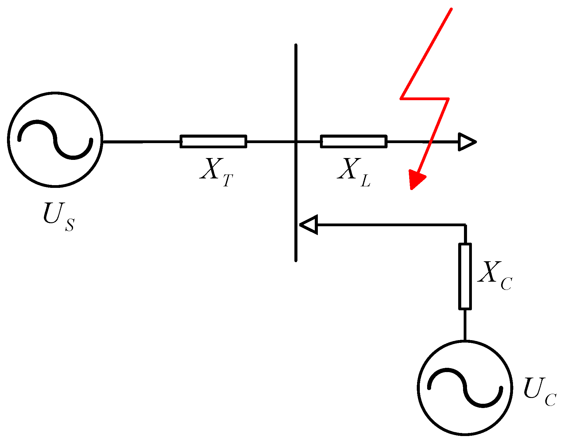
Figure 2.
Reactive power and voltage trajectories before and after synchronous condenser configuration.
Figure 2.
Reactive power and voltage trajectories before and after synchronous condenser configuration.

Figure 4.
(a) Effect of synchronous condenser capacity increase on system frequency deviation; (b) Effect of synchronous condenser capacity increase on system frequency rate of change.
Figure 4.
(a) Effect of synchronous condenser capacity increase on system frequency deviation; (b) Effect of synchronous condenser capacity increase on system frequency rate of change.
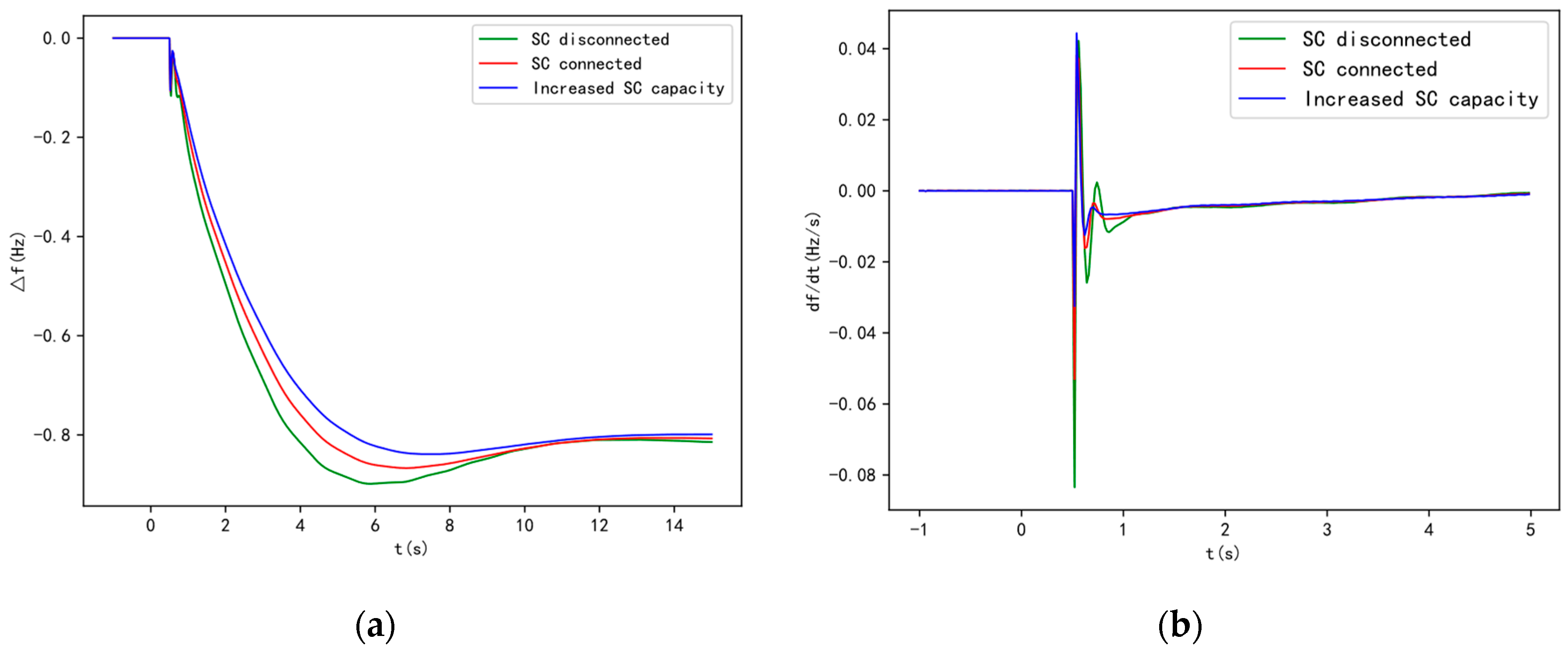
Figure 5.
Structure diagram for optimal configuration of the synchronous condenser.
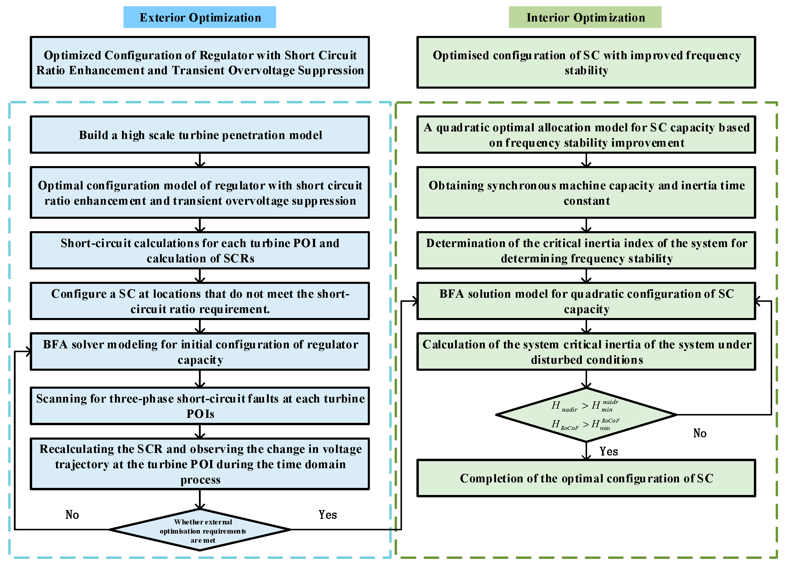
Figure 6.
IEEE 39 bus system with a high proportion of new energy.
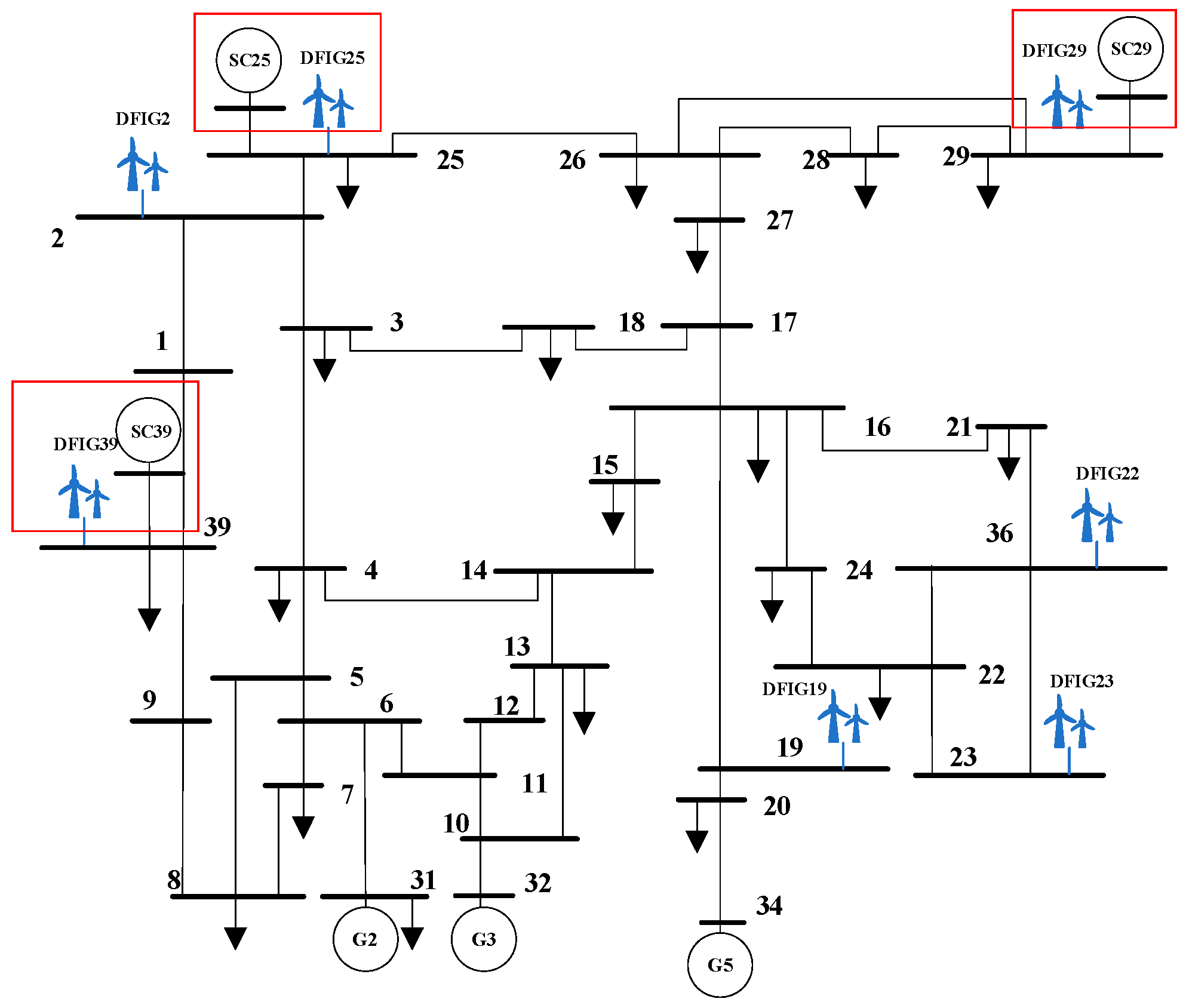
Figure 7.
Transient overvoltage traces for fault scenarios without synchronous condenser configuration.
Figure 7.
Transient overvoltage traces for fault scenarios without synchronous condenser configuration.
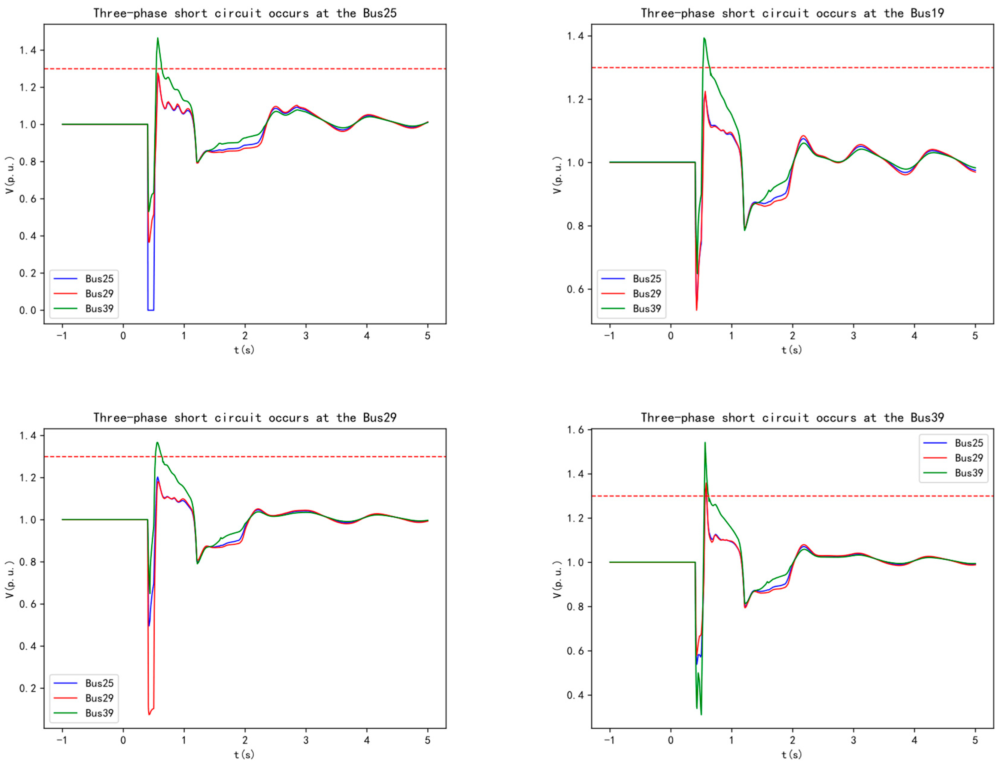
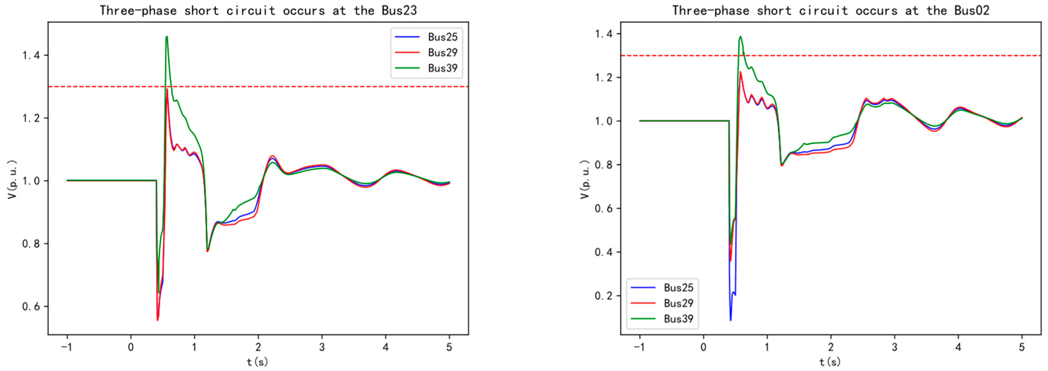
Figure 8.
Transient overvoltage traces at Bus39 for fault scenarios with synchronous condenser configuration.
Figure 8.
Transient overvoltage traces at Bus39 for fault scenarios with synchronous condenser configuration.
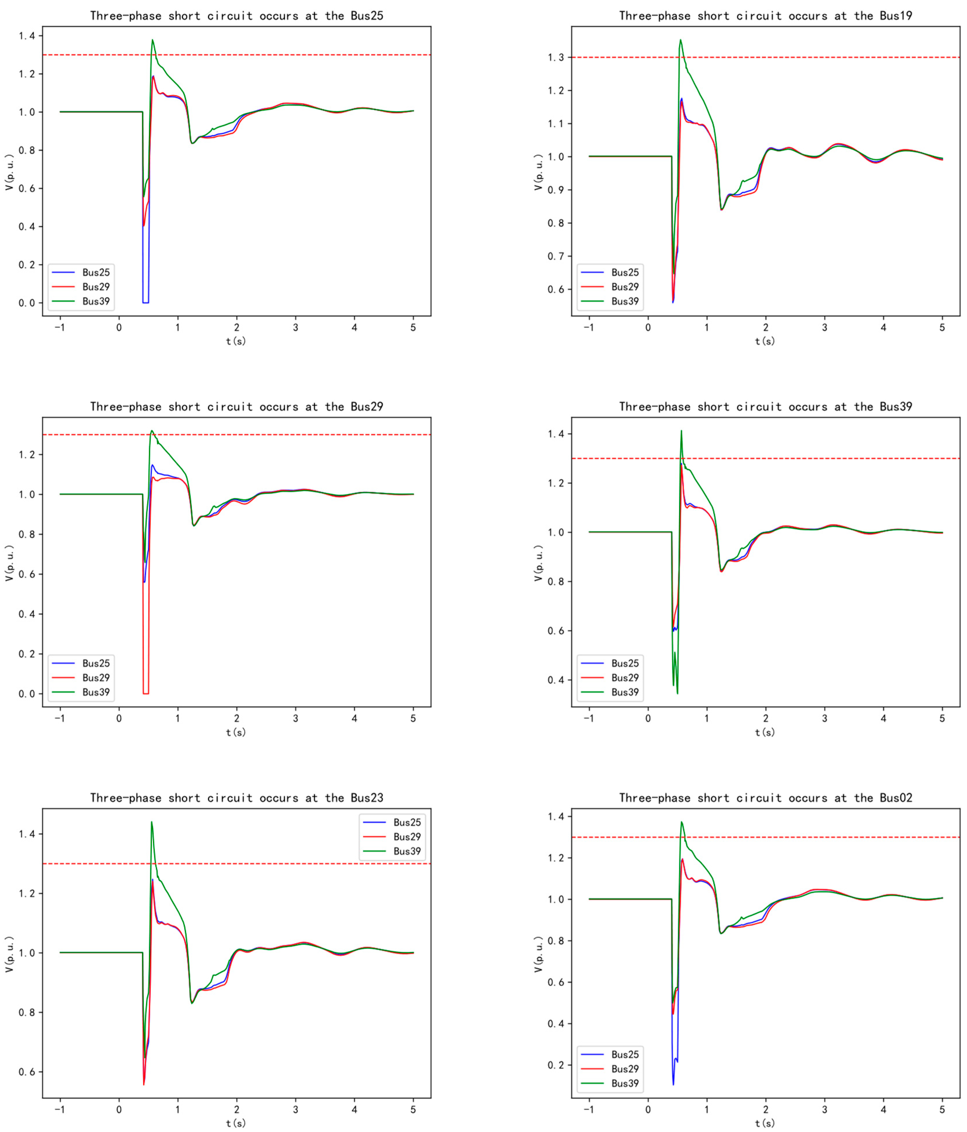
Figure 9.
Bus 39 voltage traces at different fault scenarios during the outer layer optimization of the synchronous condensers.
Figure 9.
Bus 39 voltage traces at different fault scenarios during the outer layer optimization of the synchronous condensers.
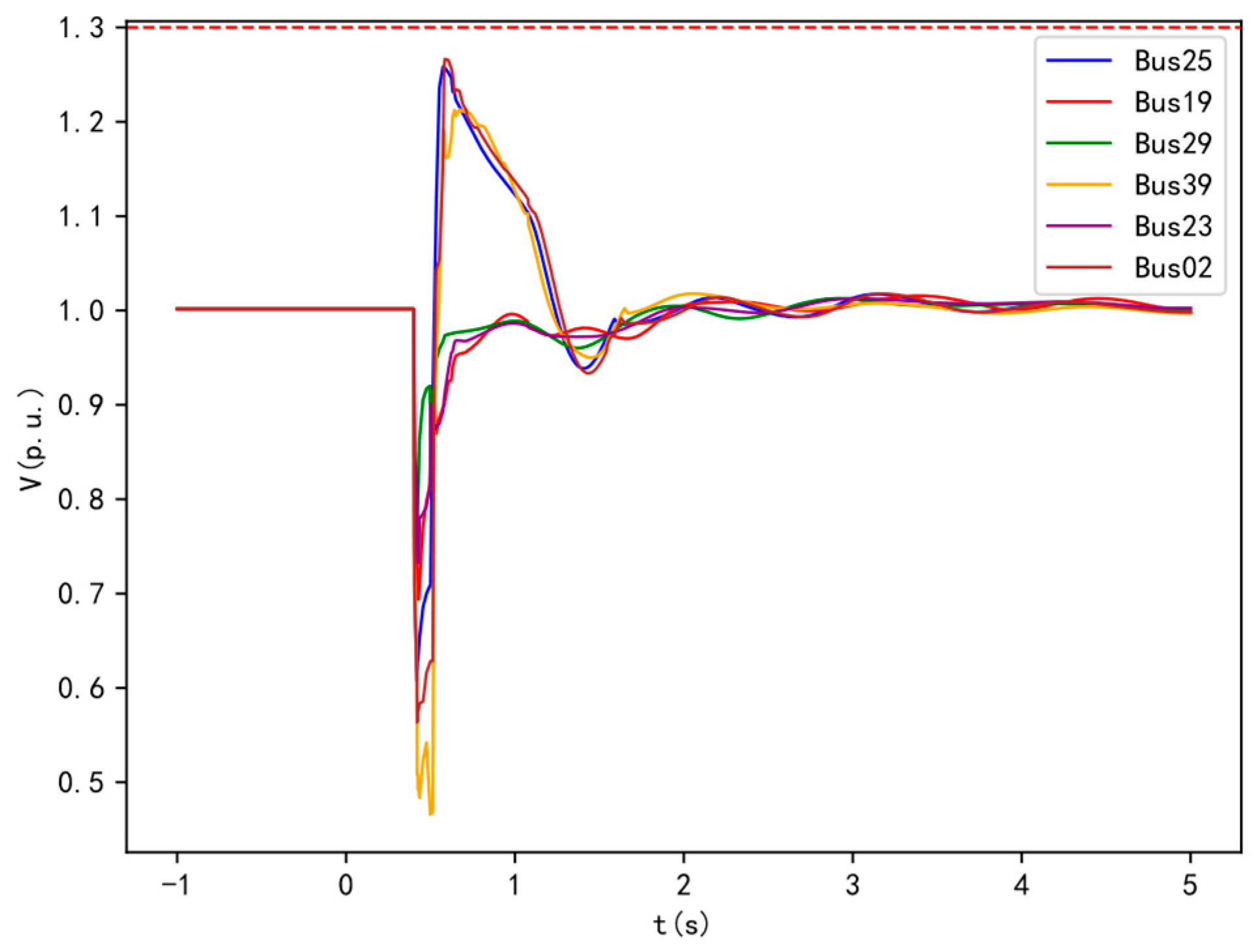
Figure 10.
The voltage trajectory at the DFIG39 wind turbine POI after the direct configuration of the synchronous condenser in fault scenarios.
Figure 10.
The voltage trajectory at the DFIG39 wind turbine POI after the direct configuration of the synchronous condenser in fault scenarios.
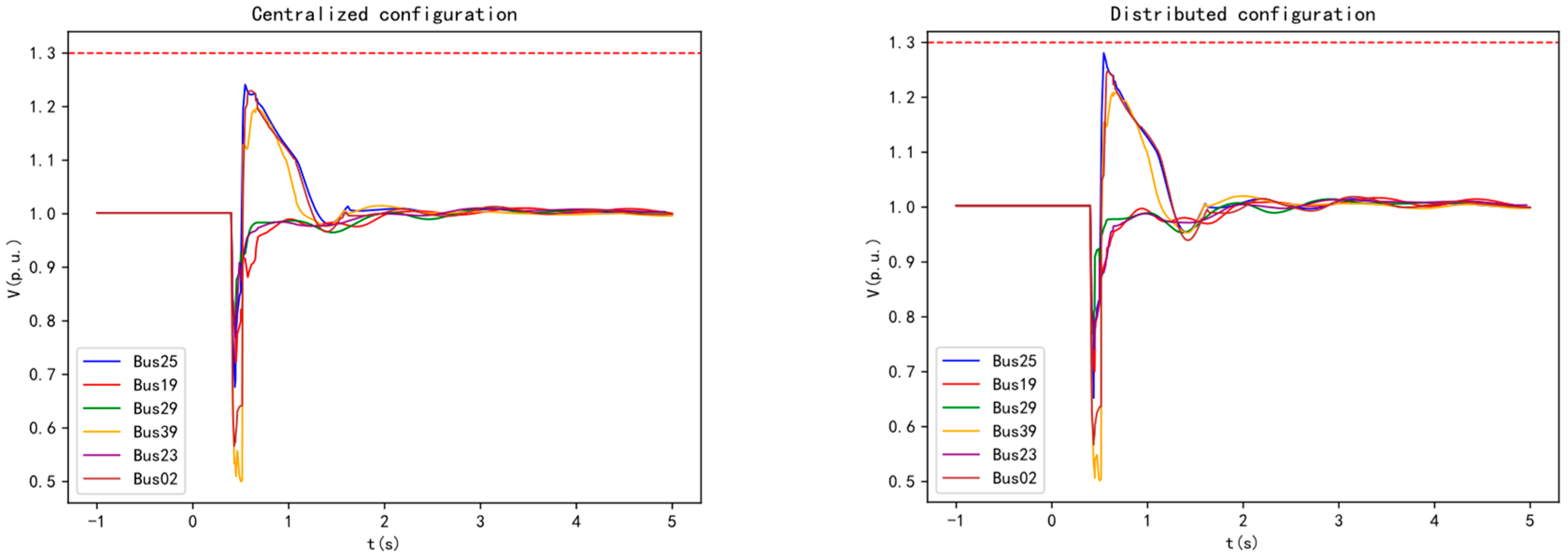
Figure 11.
Frequency dynamic response of the system after the optimized configuration of the outer layer (a) Rate of change of system frequency due to active power disturbance at Load 29; (b) System frequency deviation due to active power disturbance at Load 29; (c) Rate of change of system frequency due to active power disturbance at Load 03; (d) System frequency deviation due to active power disturbance at Load 03.
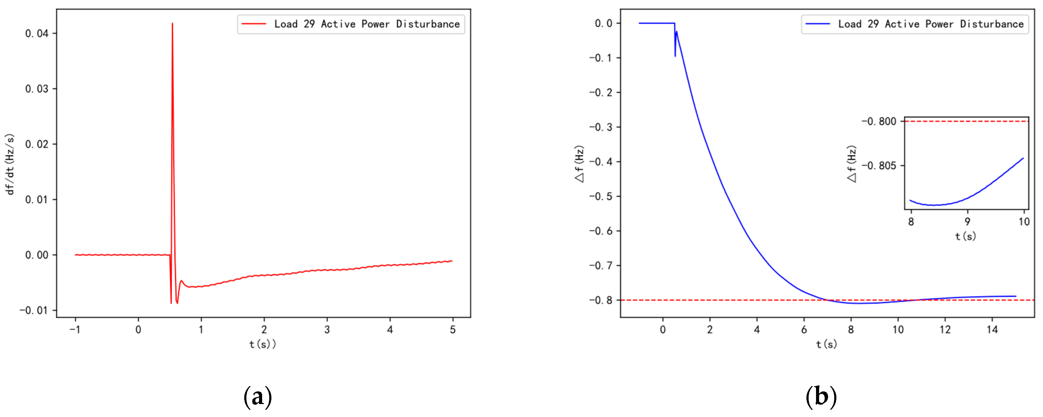
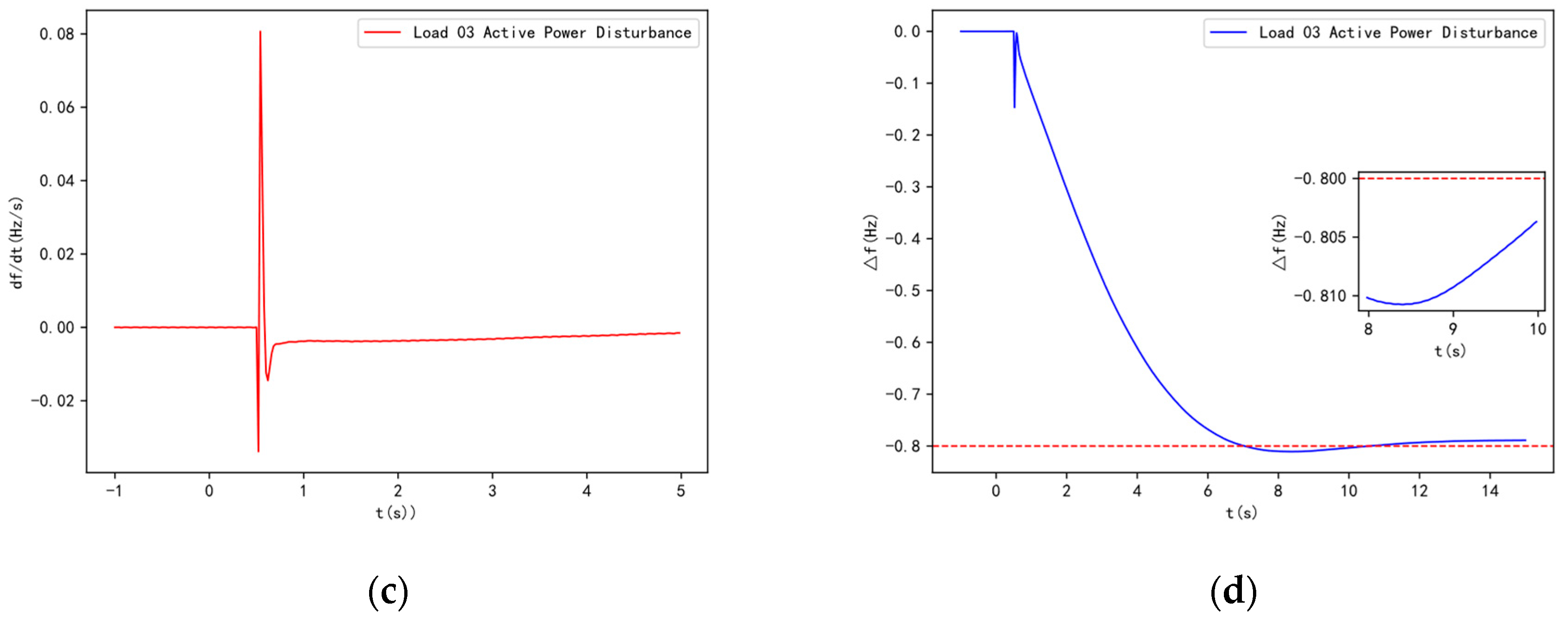
Figure 12.
Frequency dynamic response of the system after the optimized configuration of the inner layer (a) Rate of change of system frequency due to active power disturbance at Load 29; (b) System frequency deviation due to active power disturbance at Load 29; (c) Rate of change of system frequency due to active power disturbance at Load 03; (d) System frequency deviation due to active power disturbance at Load 03.
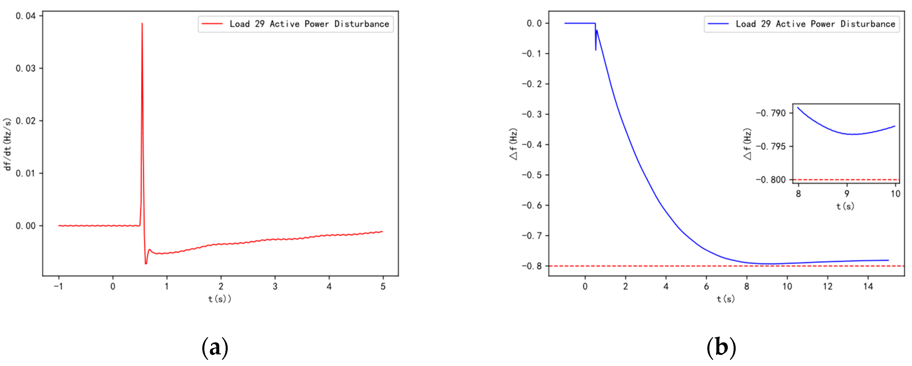
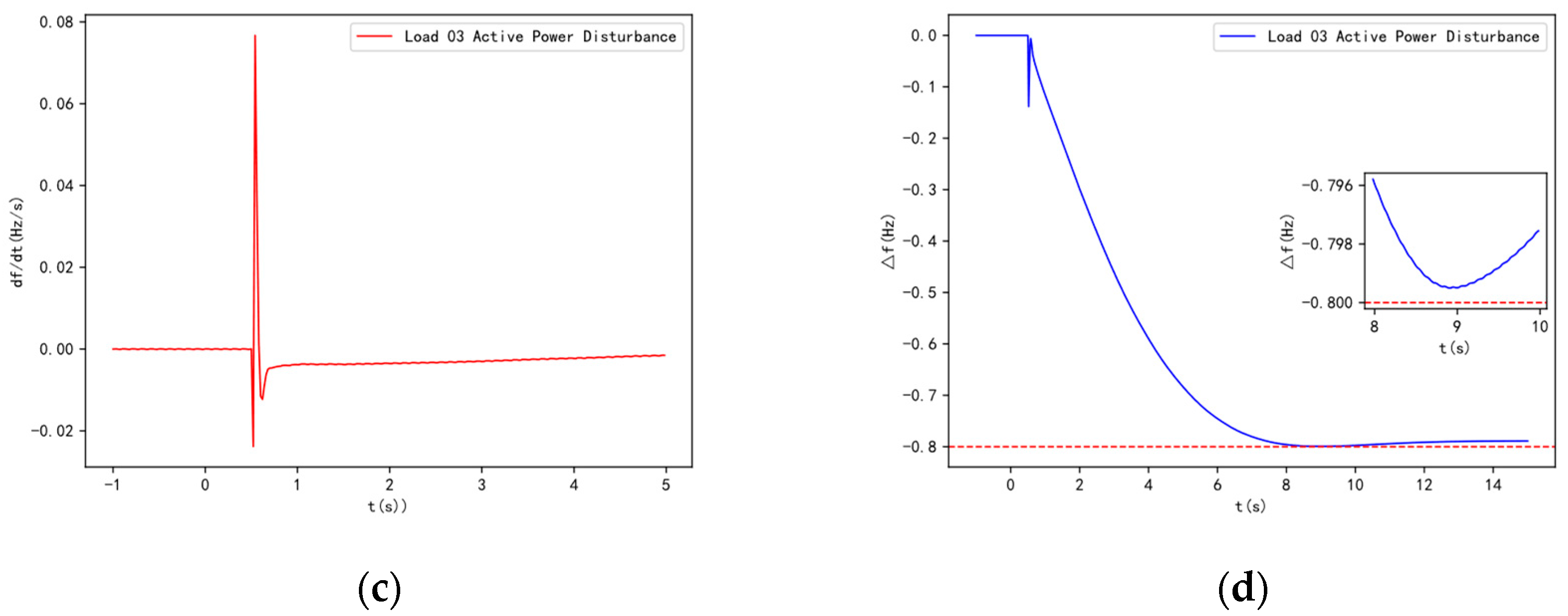
Figure 13.
Bus39 voltage traces for different fault scenarios during the optimization of the inner layer of the synchronous condensers.
Figure 13.
Bus39 voltage traces for different fault scenarios during the optimization of the inner layer of the synchronous condensers.
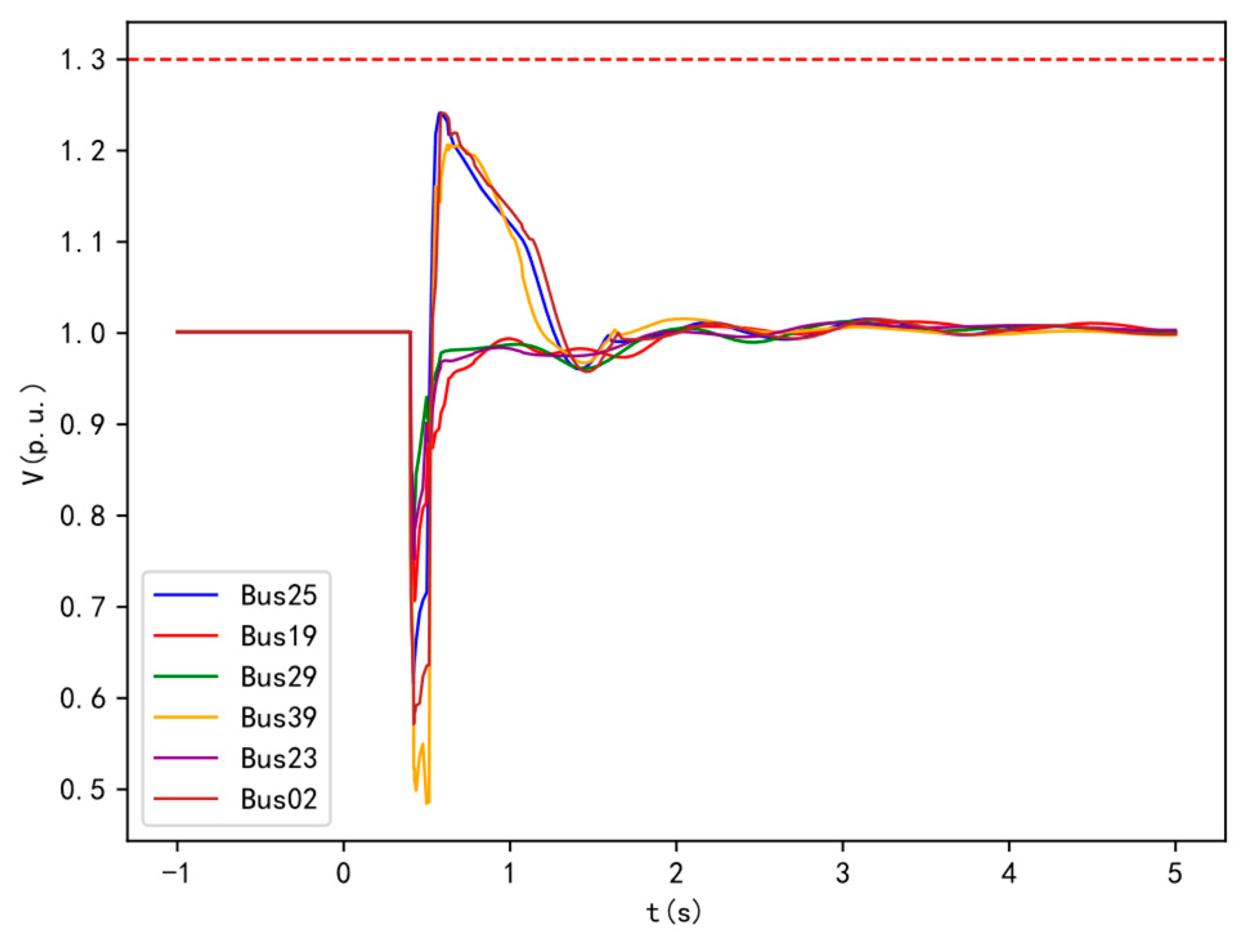
Figure 14.
Frequency dynamic response of the system with directly configured distributed synchronous condensers.
Figure 14.
Frequency dynamic response of the system with directly configured distributed synchronous condensers.
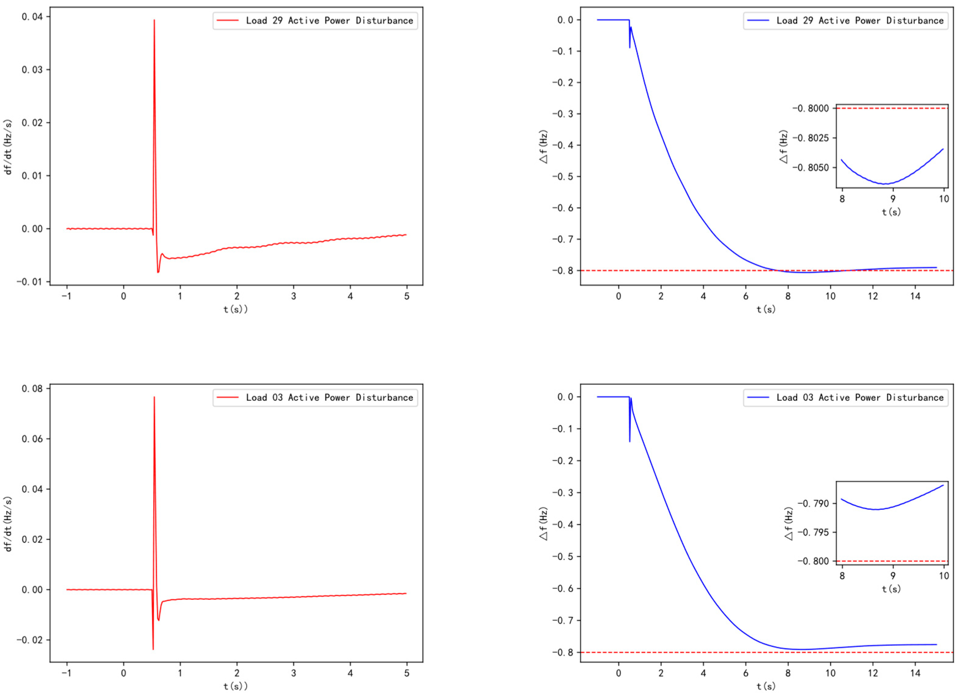
Table 1.
SCR levels at the POIs in the sending-end grid prior to synchronous condenser configuration.
Table 1.
SCR levels at the POIs in the sending-end grid prior to synchronous condenser configuration.
| wind turbine | SCR | wind turbine | SCR |
|---|---|---|---|
| DFIG2 | 10.70 | DFIG22 | 3.99 |
| DFIG39 | 1.67 | DFIG23 | 3.57 |
| DFIG19 | 6.18 | DFIG29 | 1.60 |
| DFIG25 | 2.37 |
Table 2.
The transient overvoltage and its maximum value that appeared in the wind turbines prior to the configuration of the synchronous condenser.
Table 2.
The transient overvoltage and its maximum value that appeared in the wind turbines prior to the configuration of the synchronous condenser.
| faulty bus | Wind turbines experiencing transient overvoltage (peaks) |
|---|---|
| Bus 25 | DF1G39(1.466p.u.) |
| Bus 19 | DF1G39(1.393p.u.) |
| Bus 29 | DF1G39(1.367p.u.) |
| Bus 39 | DF1G25(1.331p.u.) DF1G29(1.359p.u.) DF1G39(1.542p.u.) |
| Bus 23 | DF1G39(1.460p.u.) |
| Bus 02 | DF1G39(1.388p.u.) |
Table 3.
SCR levels at wind turbine POIs in the sending-end grid after synchronous condenser configuration.
Table 3.
SCR levels at wind turbine POIs in the sending-end grid after synchronous condenser configuration.
| wind turbine | SCR | wind turbine | SCR |
|---|---|---|---|
| DFIG2 | 13.07 | DFIG22 | 4.26 |
| DFIG39 | 2.21 | DFIG23 | 3.81 |
| DFIG19 | 6.53 | DFIG29 | 2.01 |
| DFIG25 | 2.93 |
Table 4.
The transient overvoltage and its maximum value that appeared in the wind turbines after the configuration of the synchronous condenser.
Table 4.
The transient overvoltage and its maximum value that appeared in the wind turbines after the configuration of the synchronous condenser.
| faulty bus | Wind turbines experiencing transient overvoltage (peaks) |
|---|---|
| Bus 25 | DF1G39(1.380p.u.) |
| Bus 19 | DF1G39(1.353p.u.) |
| Bus 29 | DF1G39(1.320p.u.) |
| Bus 39 | DF1G39(1.413p.u.) |
| Bus 23 | DF1G39(1.441p.u.) |
| Bus 02 | DF1G39(1.374p.u.) |
Table 7.
The SCR level at the wind turbine POI after the direct configuration of the synchronous condenser.
Table 7.
The SCR level at the wind turbine POI after the direct configuration of the synchronous condenser.
| wind turbine | SCR(centralized configuration) | SCR(distributed configuration) |
|---|---|---|
| DFIG2 | 17.18 | 15.17 |
| DFIG39 | 3.40 | 3.22 |
| DFIG19 | 6.96 | 6.83 |
| DFIG25 | 4.03 | 3.40 |
| DFIG22 | 4.14 | 4.04 |
| DFIG23 | 4.61 | 4.50 |
| DFIG29 | 3.41 | 3.21 |
Table 8.
The transient overvoltage values at the DFIG39 wind turbine POI after the direct configuration of the synchronous condenser.
Table 8.
The transient overvoltage values at the DFIG39 wind turbine POI after the direct configuration of the synchronous condenser.
| faulty bus | centralized configuration | distributed configuration |
|---|---|---|
| Bus 25 | DF1G39(1.241p.u.) | DF1G39(1.281p.u.) |
| Bus 39 | DF1G39(1.197p.u.) | DF1G39(1.197p.u.) |
| Bus 02 | DF1G39(1.230p.u.) | DF1G39(1.247p.u.) |
Table 9.
The required capacity of the synchronous condenser under different configuration methods.
| synchronous condenser configuration method | total capacity/MVA |
|---|---|
| direct configuration of centralized SCs | 710 |
| direct configuration of distributed SCs | 550 |
| the optimized configuration method of this paper | 500 |
Table 10.
The system inertia and critical inertia after the outer layer optimization configuration.
| power disturbance | critical inertia of the system | the system inertia after outer layer optimization | ||
|---|---|---|---|---|
| Load 29 power disturbance at 55% | 780 | 1864.76 | ||
| 3259.02 | 3220.80 | |||
| Load 03 power disturbance at 70% | 1125 | 1394.39 | ||
| 4700.51 | 4638.22 | |||
Table 11.
The system inertia and critical inertia after the inner layer optimization configuration.
| power disturbance | critical inertia of the system | the system inertia after outer layer optimization | ||
|---|---|---|---|---|
| Load 29 power disturbance at 55% | 780 | 2021.51 | ||
| 3530.58 | 3560.75 | |||
| Load 03 power disturbance at 70% | 1125 | 1466.56 | ||
| 4980.28 | 4983.36 | |||
Table 12.
Level of wind turbine SCR after the optimal configuration of the inner layer of the synchronous condensers.
Table 12.
Level of wind turbine SCR after the optimal configuration of the inner layer of the synchronous condensers.
| wind turbine | SCR | wind turbine | SCR |
|---|---|---|---|
| DFIG2 | 15.77 | DFIG22 | 4.54 |
| DFIG39 | 3.25 | DFIG23 | 4.08 |
| DFIG19 | 6.88 | DFIG29 | 3.50 |
| DFIG25 | 3.58 |
Table 13.
The transient overvoltage value at the DFIG39 wind turbine POI after the inner layer optimization of the synchronous condenser.
Table 13.
The transient overvoltage value at the DFIG39 wind turbine POI after the inner layer optimization of the synchronous condenser.
| faulty bus | Wind turbines experiencing transient overvoltage (peaks) |
|---|---|
| Bus 25 | DF1G39(1.242p.u.) |
| Bus 39 | DF1G39(1.206p.u.) |
| Bus 02 | DF1G39(1.240p.u.) |
Table 14.
The system inertia and critical inertia under two configuration methods.
| power disturbance | direct allocation of distributed synchronous condensers/s | Inner layer optimization configuration of synchronous condensers/s | ||||||||
|---|---|---|---|---|---|---|---|---|---|---|
| Load 29 power disturbance | 780 | 1979.9 | 780 | 2021.5 | ||||||
| 3414.2 | 3387.1 | 3530.6 | 3560.7 | |||||||
| Load 03 power disturbance | 1125 | 1426 | 1125 | 1466.6 | ||||||
| 4868.4 | 4923.4 | 4980.3 | 4983.4 | |||||||
Table 15.
The required capacity of the synchronous condenser under different configuration methods.
| synchronous condenser configuration method | total capacity/MVA |
|---|---|
| direct configuration of distributed synchronous condensers | 700 |
| the optimized configuration method of this paper" | 625 |
Disclaimer/Publisher’s Note: The statements, opinions and data contained in all publications are solely those of the individual author(s) and contributor(s) and not of MDPI and/or the editor(s). MDPI and/or the editor(s) disclaim responsibility for any injury to people or property resulting from any ideas, methods, instructions or products referred to in the content. |
© 2024 by the authors. Licensee MDPI, Basel, Switzerland. This article is an open access article distributed under the terms and conditions of the Creative Commons Attribution (CC BY) license (http://creativecommons.org/licenses/by/4.0/).
Copyright: This open access article is published under a Creative Commons CC BY 4.0 license, which permit the free download, distribution, and reuse, provided that the author and preprint are cited in any reuse.


