Preprint
Article

This version is not peer-reviewed.

Movement and Uncertainty of the Center of Relativistic Energy in an Isolated Frame of Reference

Submitted:

16 January 2025

Posted:

17 January 2025

Read the latest preprint version here

Abstract

We study whether the center of relativistic energy (CRE) is always constant in an isolated frame of reference (IFR). First, we assume that two objects, in a moving IFR (MIFR), move parallel to and very close to a coordinate axis from opposite directions and with equal speed. Each length in the direction of travel of the objects is much longer than that perpendicular to the direction of travel of them. Here it is assumed that the location of the CRE (LCRE) of each object, in the initial condition, is very close to the coordinate axis. When they become perfectly symmetric with respect to the coordinate axis, the forces perpendicular to the direction of travel of the objects are applied to each CRE and thereby a perfectly inelastic collision between them occurs on the coordinate axis. The combined object (CO) resulting from the perfectly inelastic collision begins to rotate because the momentum of the object before the combination acts like the moment of force on the CO. For simplicity, we examine the energy distribution of the CO when it becomes perpendicular to the coordinate axis due rotation. The magnitude of velocity of each minute portion (MP) symmetrical with respect to the coordinate axis is different depending on whether the direction of each rotational velocity is the same or opposite to the direction of travel of the MIFR. Then the energy of each MP is not the same. As a result, we quantitatively demonstrate that the LCRE of the CO significantly moves from the vicinity of the coordinate axis. Therefore, we conclude that the LCRE in the MIFR is not necessarily invariant. Second, we suppose a process in which a force causes a negative acceleration on a moving object (MO) and thereafter the MO eventually comes to rest. What is considered here is the LCRE when the MO comes to rest and Lorentz contraction of it disappears. We pay attention to the position of the force applied to the MO because the transmission time of force (TTF) inside the MO may vary depending on the position of the MO where the force is applied. As a result, we find that the position at which the MO comes to rest differs depending on the TTF inside the MO. Therefore, we conclude that the LCRE in an IFR differs depending on the position of the MO where the force is applied, in other words, it in an IFR is not necessarily uniquely determined.

Keywords: 
;  

1. Introduction

It is regarded as one of the most fundamental principles of physics that the location of center of mass in an IFR is always constant. From this principle, Einstein has derived the equivalence of mass and energy in special relativity (SR) .1,2 According to it, the location of the center of energy (CE) is always constant in an IFR.3-5 This is called the CE theorem in SR.3-5 The concept of CE is the relativistic generalization of center of mass because it includes not only rest energy in the form of mass but also all forms of energy.3 A research demonstrates, using the CE theorem, that relativistic effects appear in rotational motion which results from cutting superposed parts of mechanical transverse waves on a medium traveling at non-relativistic speeds.6 On the other hand, we cannot find any previous researches that refute the CE theorem.
Nevertheless, we consider the existence of physical phenomena in which the CE theorem does not hold, i.e., those in which the CRE in the IFR is not necessarily constant. We examine whether such physical phenomena occur in a MIFR and when a MO comes to rest.
First, we set up a physical phenomenon in which two objects approach parallel to a coordinate axis from opposite directions in the MIFR. When they are perfectly symmetric with respect to the coordinate axis, the forces perpendicular to the direction of travel of the objects are applied to each CRE. Then a perfectly inelastic collision between them occurs on the coordinate axis, and the CO begins to rotate due to each momentum of the objects before the combination. We examine whether the LCRE of the CO in rotational motion is different from that of the two objects in an initial condition.
Second, suppose a process in which a force causes a negative acceleration on a MO, thereafter it eventually comes to rest and Lorentz contraction of it disappears. Here it is important to pay attention to the position of the force applied to the MO. This is because the TTF inside the MO may vary depending on the position where the force is applied. We examine whether, when the MO comes to rest, its LCRE differs depending on the position of it to which the force is applied, considering the TTF inside each MO.

2. Movement of the LCRE in a MIFR

2.1. Thought Experiment

We presuppose two inertial frames of reference, S and S , that are in a state of uniform relative motion to each other. S moves with constant velocity V in the positive direction of the x axis in S 
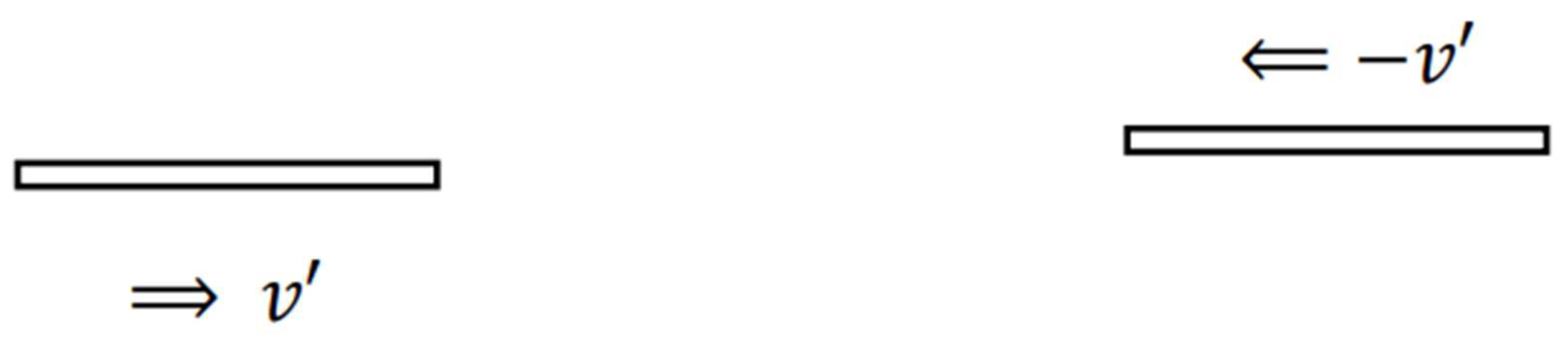
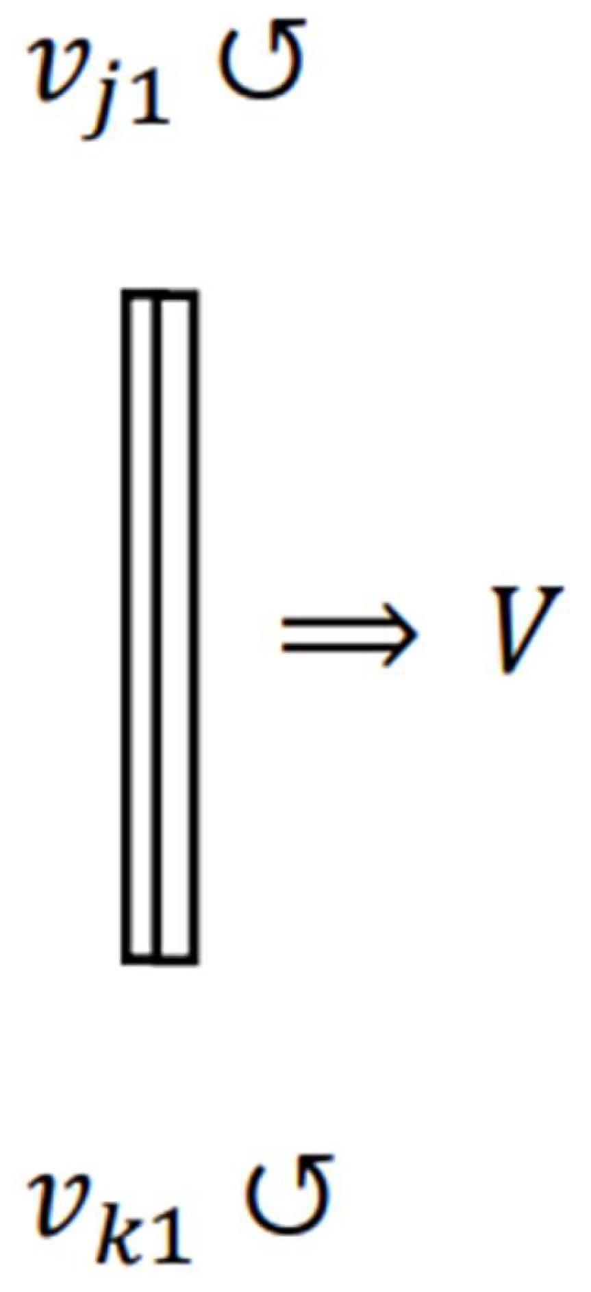
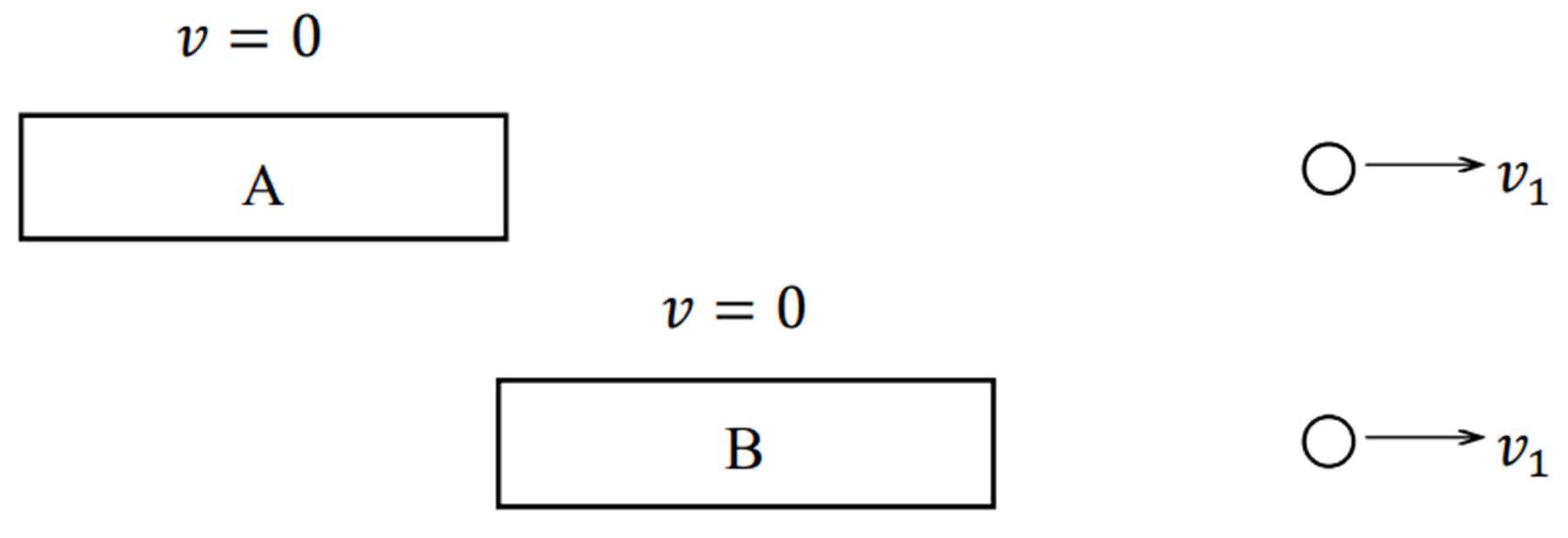
. Moreover, assume that the two objects having the same rest mass (RM) and the same size, in S , move parallel to the x -axis from opposite directions and with the same speed as shown in Figure 1. Those velocities are v and v , respectively. The two objects are symmetrical to the x -axis, and they are located very close to it. Each length in the direction of travel of the objects is much longer than that perpendicular to the direction of travel of them. Let y -axis be the axis perpendicular to the x -axis. In addition, assume that the origin of the y -axis is on the x -axis.
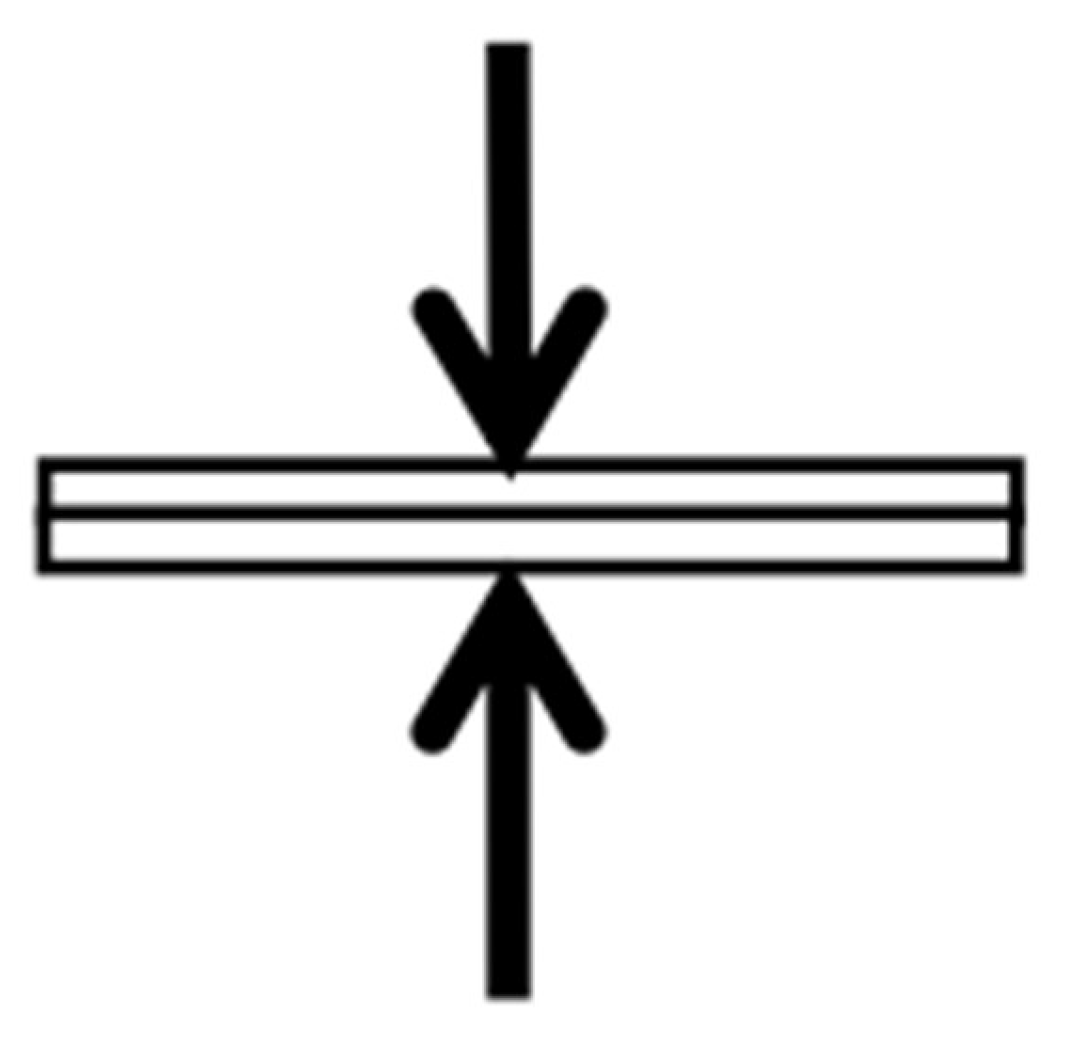
When the objects become perfectly symmetric with respect to the x -axis, as shown in Figure 2, the forces perpendicular to the direction of travel of them are applied to the CRE of each object in the MIFR. The forces result in a perfectly inelastic collision between the objects and thereby they combine. Here, as shown in Figure 2, the length in the direction of the y -axis of the CO is extremely short compared to that along the x -axis.
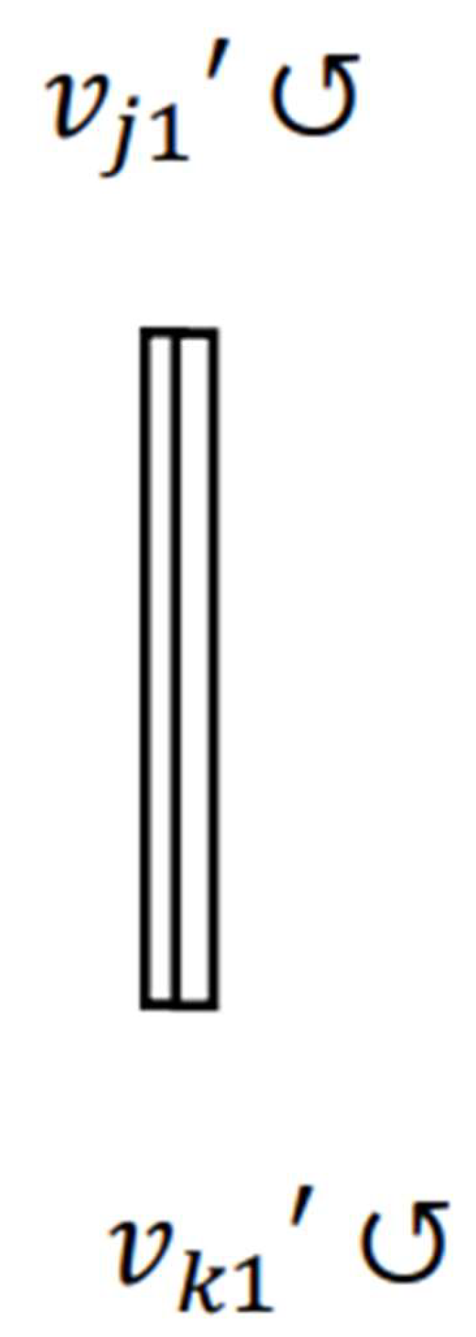
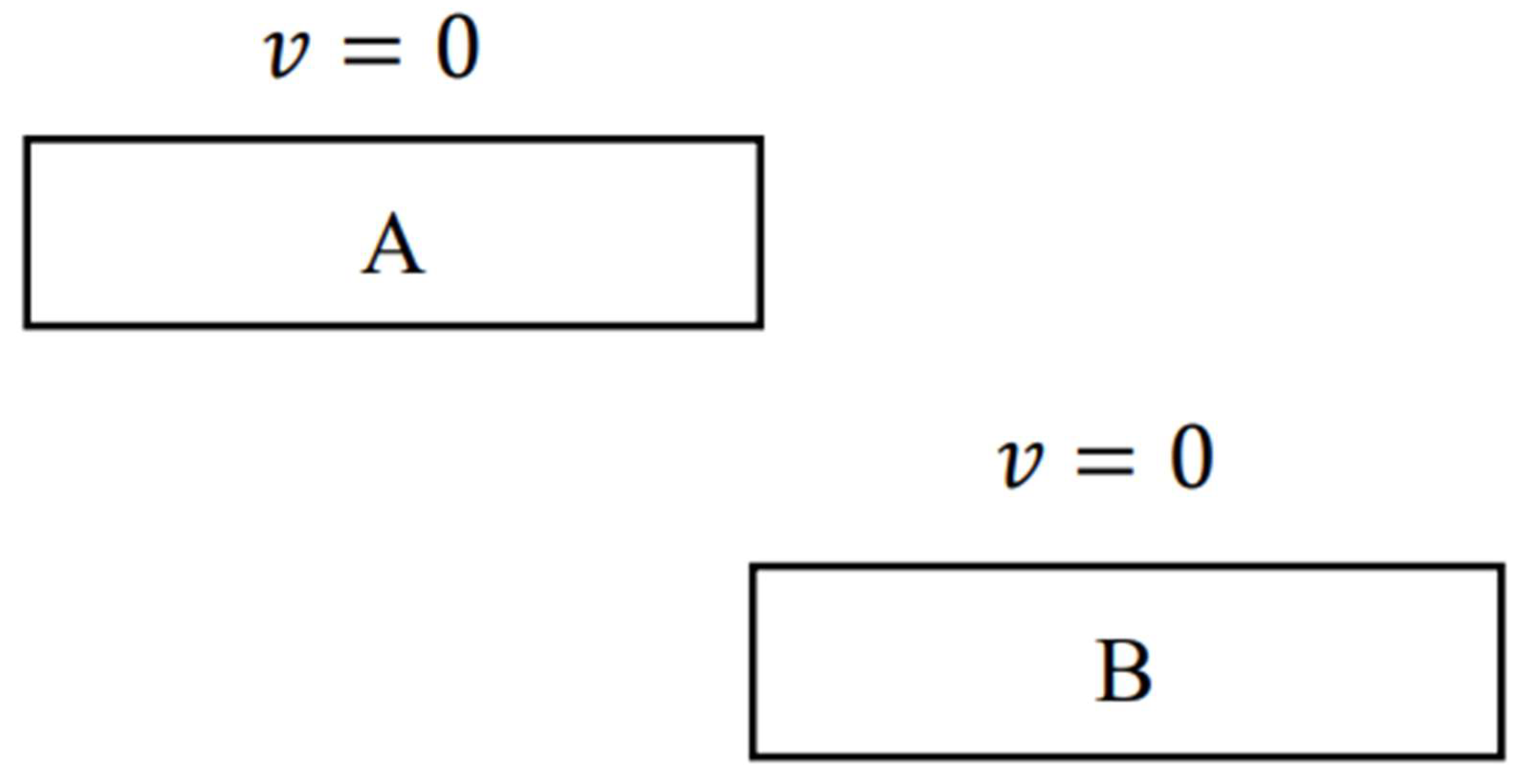
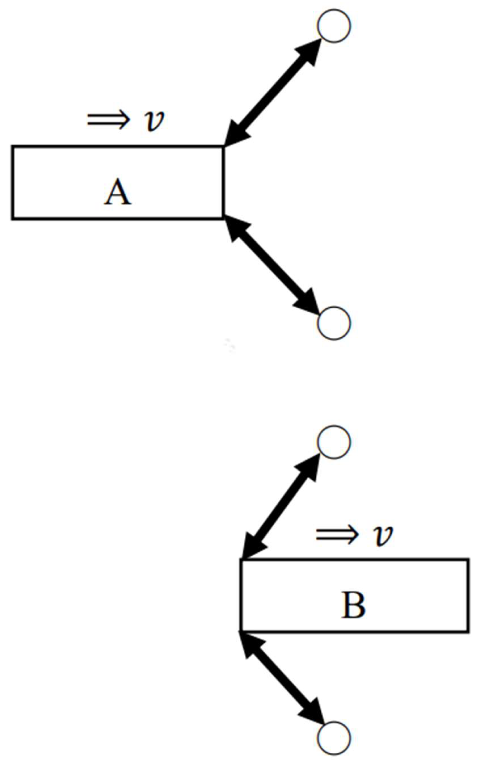
After the objects combine, the translational motion of each object stops, and a recoilless rotational motion of the CO occurs counterclockwise as shown in Figure 3. The reason for this is that each momentum of the objects before the combination between them acts like the moment of force on the CO. Suppose that this rotational motion takes place around y = 0 . When the CO rotates and becomes perpendicular to the x -axis, the distribution of RM of the CO is symmetric with respect to the x -axis. Let v j 1 be a velocity of a MP of the CO that lies in the range where y > 0 . Similarly, let v k 1 be a velocity of a MP of the CO that exists in the range where y < 0 . Suppose that a MP with v j 1 and one with v k 1 are symmetrical with respect to the x -axis. When observed from S , v j 1 and v k 1 of each MP are opposite in direction but equal in magnitude, i.e., v j 1 = v k 1 .
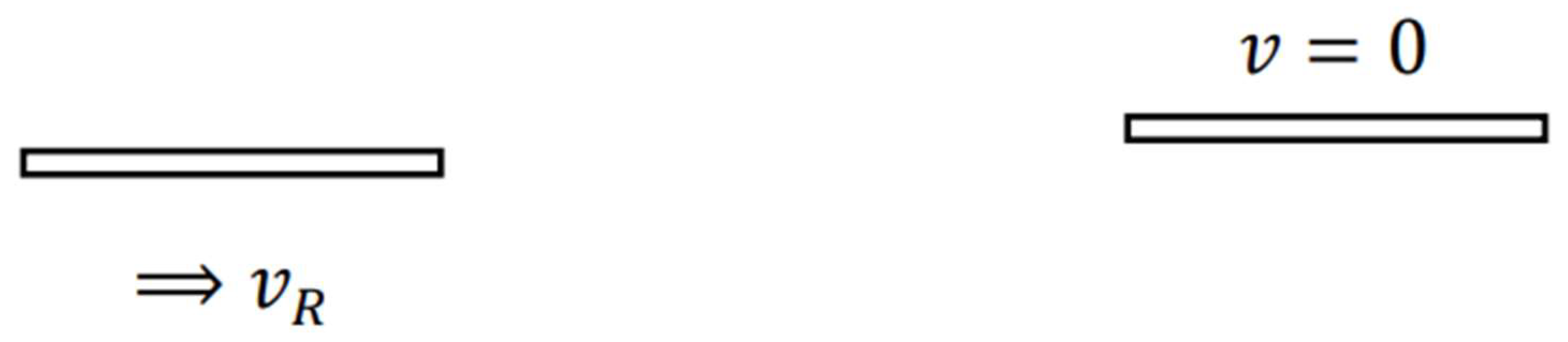
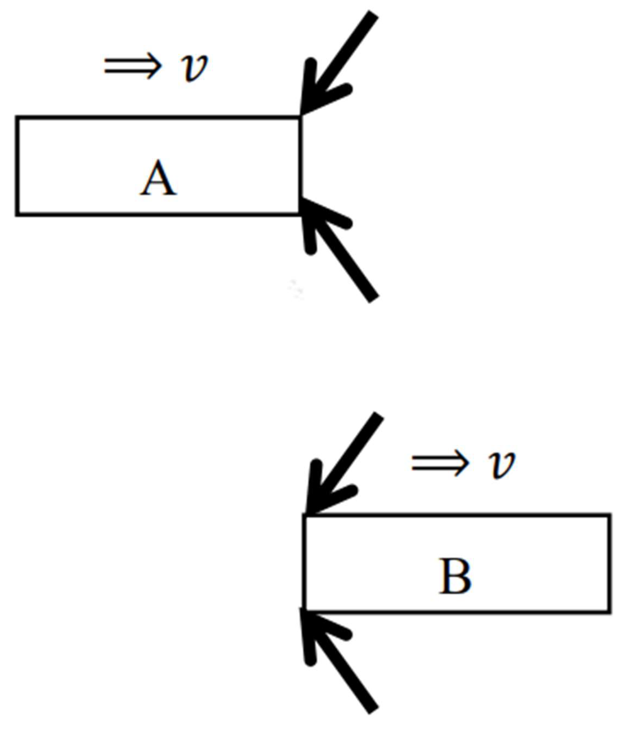
We will observe these phenomena from S . Suppose that, when observed from S , V = v . Then, as shown in Figure 4, the object on the right is stationary, and that on the left is moving at a velocity v R parallel to the x -axis.
Here v R is expressed as v + V / 1 + v V / c 2 based on the law of velocity addition in SR. For simplicity, if we assume that all velocities here are non-relativistic those which Newtonian mechanics is applicable, v R = v + V .
After a perfectly inelastic collision between the objects occurs, the CO starts rotating around y = 0 . When the CO rotates and becomes perpendicular to the x -axis, the length in the direction of the x -axis of the CO is extremely short as shown in Figure 5. On the other hand, the center of RM of the CO moves at V in the positive direction of the x -axis in S since its center of RM is stationary in S . This is also shown in Figure 5. Here let v j 1 be a velocity of a MP of the CO in the range where y > 0 . This corresponds to v j 1 in S . In addition, let v k 1 be a velocity of a MP of the CO in the range where y < 0 . This corresponds to v k 1 in S . Here it is assumed that a MP with v j 1 and one with v k 1 are symmetrical with respect to the x -axis. When observed from S , v j 1 and v k 1 of each MP are different in magnitude depending on whether the x-component of each rotational velocity is the same or opposite to the direction of travel of the CO.

2.2. Numerical Calculation of the CE Based on Newtonian Mechanics

For simplicity, we perform the numerical calculation for the CE in the above thought experiment based on Newtonian mechanics. We examine the location of the CE (LCE) before and after the combination of two objects. Let m be the RM. Since the rest energy of the CO remains symmetrical with respect to the x -axis, we will calculate only its kinetic energy, KE, 1 / 2 m v 2 , by substituting concrete values. Here, the units of various physical quantities will be omitted. The energy produced by the perfectly inelastic collision that becomes thermal energy leads to an increase in the RM of the object. This increase is symmetric with respect to the x -axis.
We assume that each object consists of 10 minute portions (MPs) which have the same RM and shape respectively in S . Each object in Figure 1 consists of 10 equal MPs parallel to y -axis. Each MP has a RM of 1 and is a square with side 1 on the x - y   plane. Each object has a RM of 10.0 , so the sum of the two is 20.0 . Since each object is moving at the uniform velocity of v = 10.0 or v = 10.0 along the x -axis, the velocities of the MPs are also v = 10.0 or v = 10.0 respectively. Let D and D be the distance from the x -axis to the center of each object and assume that they are 0.5 and 0.5 respectively.
We analyze the physical quantities of the object that becomes perpendicular to the x -axis due to the rotational motion after the combination. The CO in Figure 3, which has the length of 10 in the direction perpendicular to the x -axis, consists of 10 equal MPs parallel to the x -axis. Each MP has a length of 1 in the direction perpendicular to the x -axis and a length of 2 in the direction of the x -axis. The RM of each MP, which is generated by the combination of two objects, becomes 1.0 + 1.0 = 2.0 . In the direction perpendicular to the x -axis, the centers of each MP are located at distances of 4.5 , 3.5, 2.5, 1.5, 0.5, 0.5, 1.5, 2.5, 3.5, and 4.5 from the center of rotation, in other words, the x -axis.
The circumferences of the centers of the MPs at positions of 4.5 and 0.5 when they rotate once are 9.0 π and 1.0 π , respectively. Hence, the angular velocity of the former is 9.0 times that of the latter. Similarly, the angular velocity of the MP at 4.5 is approximately 1.3, 1.8 and 3.0 times the angular velocities of the MPs at 3.5, 2.5 and 1.5, respectively. If we assign the angular velocity to the center of each MP according to those magnifications, the angular velocities of the MPs at locations 4.5, 3.5, 2.5,1.5 and 0.5 are approximately 2.7, 2.1, 1.5, 0.9, 0.3, respectively. On the other hand, we can consider each MP at positions 0.5, 1.5, 2.5, 3.5, and 4.5 in the same way. The angular velocities of the MPs at locations 0.5, 1.5, 2.5, 3.5 and 4.5 are approximately 0.3, 0.9, 1.5, 2.1 and 2.7 respectively.
We consider the above physical phenomenon from S . Before two objects combine and begin to rotate, the velocity of one object is 10.0 + 10.0 = 20.0 , and that of the other object is 10.0 + ( 10.0 ) = 0 . The momentum, m v , of the former, which has the RM of 10.0 and the velocity of 20.0 , is 10.0 × 20.0 = 200.0 . On the other hand, the momentum of the object with the velocity of 0 is zero. The center of KE of two objects is at location 0.5 in the direction perpendicular to the x -axis since the center of the object having KE is at that location. After two objects combine and begin to rotate, the velocity of the center of the CO, which becomes the RM of 20.0 due to the combination, is 200.0 ÷ 20.0 = 10.0 .
We examine the velocity of each MP of the CO when they become perpendicular to the x -axis due to the rotation. Since the center of rotation of the CO has the above velocity of 10 and the relative velocities of the MPs to it are the values as their angular velocities we have already calculated, the velocity of each MP is:
10.0 + 2.7 = 7.3 ,   10.0 + 2.1 = 7.9 ,   10.0 + 1.5 = 8.5 , 10.0 + 0.9 = 9.1 ,   10.0 + 0.3 = 9.7 ,   10.0 + 0.3 = 10.3 , 10.0 + 0.9 = 10.9 ,   10.0 + 1.5 = 11.5 ,   10.0 + 2.1 = 12.1 , 10.0 + 2.7 = 12.7 . ( 1 )
Then the KE of each MP is:
1 / 2 × 2.0 × 7.3 2 = 53.29 ,   1 / 2 × 2.0 × 7.9 2 = 62.41 , 1 / 2 × 2.0 × 8.5 2 = 72.25 ,   1 / 2 × 2.0 × 9.1 2 = 82.81 , 1 / 2 × 2.0 × 9.7 2 = 94.09 ,   1 / 2 × 2.0 × 10.3 2 = 106.09 , 1 / 2 × 2.0 × 10.9 2 = 118.81 ,   1 / 2 × 2.0 × 11.5 2 = 132.25 , 1 / 2 × 2.0 × 12.1 2 = 146.41 ,   1 / 2 × 2.0 × 12.7 2 = 161.29 . ( 2 )
As a result, if let T K E be total KE, we get the following T K E :
53.29 + 62.41 + 72.25 + 82.81 + 94.09 + 106.09 + 118.81 + 132.25 + 146.41 + 161.29 = 1029.7 . ( 3 )
We consider the center of KE of the MPs when they become perpendicular to the x -axis. As above mentioned, the centers of the MPs are located at distances of 4.5 , 3.5, 2.5, 1.5, 0.5, 0.5, 1.5, 2.5, 3.5, and 4.5 from the x -axis. If let K E D be distance from the x -axis multiplied by KE, the distribution of KE of each MP is given as the following K E D :
53.29 × 4.5 = 239.80 ,   62.41 × 3.5 = 218.44 72.25 × 2.5 = 180.63 ,   82.81 × 1.5 = 124.22 , 94.09 × 0.5 = 47.05 ,   106.09 × 0.5 = 53.05 , 118.81 × 1.5 = 178.22 ,   132.25 × 2.5 = 330.63 , 146.41 × 3.5 = 512.44 ,   161.29 × 4.5 = 725.81 . ( 4 )
Furthermore, the sum of the K E D is:
239.80 + 218.44 + 180.63 + 124.22 + 47.05 + 53.05 + 178.22 + 330.63 + 512.44 + 725.81 = 990.01 . ( 5 )
Let LCKE be the location of the center of KE. We can derive the LCKE of the CO using the following formula:
K E D + K E D T K E . ( 6 )
Substituting Eq. (5) into the numerator in Eq. (6) and Eq. (3) into the denominator in Eq. (6), the LCKE of the MPs is given:
990.01 1029.7 = 0.96 . ( 7 )
Therefore, the LCKE of the CO moves by:
0.96 0.5 = 0.46 . ( 8 )
As a result, since the rest energy of the CO does not change, its LCE also moves in the negative direction on the y -axis no matter what the specific numbers are.

2.3. Movement of the LCRE

We demonstrate the LCRE before and after the combination of two objects based on the results of calculations of the CE according to Newtonian mechanics. We confirm the LCRE of the two objects before the combination between them. The formula for the RE is expressed by:
R E ( v ) = m c 2 1 v 2 / c 2 ( 9 )
where c is speed of light. Then the R E of the object stationary, R E ( 0 ) , by substituting 0 for v in Eq. 9, is expressed as follows:
R E ( 0 ) = m c 2 1 0 2 / c 2 = m c 2 . ( 10 )
By contrast, the R E of the object having v R = v + V / 1 + v V / c 2 , R E ( v R ) , by substituting v + V / 1 + v V / c 2 for v in Eq. 9, is as follows:
R E ( v R ) = m c 2 1 v + V / 1 + v V / c 2 2 / c 2 . ( 11 )
Since v + V / 1 + v V / c 2 > 0 , 1 v + V / 1 + v V / c 2 2 / c 2 < 1 . Hence, since R E ( v R ) > m c 2 , we get:
R E v R > R E 0 . ( 12 )
Since the distance in the direction perpendicular to the x -axis is not under Lorentz contraction, that from the center of each object to the x -axis is 0.5. Then the LCRE of them is:
m c 2 × 0.5 + m c 2 1 10 + 10 / 1 + 10 × 10 / c 2 2 / c 2 × 0.5 . ( 13 )
where m = 10 . From inequality (12), the distribution of RE of the two objects is not symmetric to the x -axis, and the LCRE of them is within the range y = 0 > y = 0.5 .
Now we consider the LCRE of the CO when it becomes perpendicular to the x -axis in S . We compare the RE of each MP of the CO located symmetrically to the x -axis. The value of numerator in Eq. (9), m c 2 is equal with respect to every MP since each MP has the same RM and c is the constant. Hence, the difference in RE between the MPs is determined by 1 v 2 / c 2 which is the value of denominator in Eq. (9).
Each MP of the CO in the range where y > 0 , since the CO rotates counterclockwise in S , has the velocity which is the sum of its negative rotational one and the positive translational one of S . By contrast, Each MP of the CO in the range where y < 0 has the velocity which is the sum of its positive rotational one and the positive translational one of S since the CO rotates counterclockwise in S .
The velocity of a MP is expressed as:
v j 1 = v j 1 + V 1 v j 1 V c 2 o r v k 1 = v k 1 + V 1 + v k 1 V c 2 . ( 14 )
We can assume that the values of V / c , v j 1 / c and v k 1 / c are extremely small, in other words, 1 v j 1 V / c 2   1 and 1 + v k 1 V / c 2   1 . Hence, since the values   v j 1 and   v k 1 are almost determined by each numerator, they are approximately equal to v j 1 + V and v k 1 + V respectively. This corresponds to the velocity of each MP obtained by the numerical calculation based on Newtonian mechanics above. Furthermore, since v j 1 + V < v k 1 + V , we obtain:
v j 1 < v k 1 . ( 15 )
Moreover, substituting v j 1 and v k 1 into v in Eq. (9) respectively, we have   1   v j 1 2 / c 2 and 1   v k 1 2 / c 2 . From inequality (15), we get:
1 v j 1 2 / c 2 > 1 v k 1 2 / c 2 . ( 16 )
If let R E j 1 and R E k 1 be the RE of a MP having v j 1 and that of a MP having v k 1 , respectively, each RE is expressed:
R E j 1 = m c 2 1 v j 1 2 / c 2 , R E k 1 = m c 2 1 v k 1 2 / c 2 . ( 17 )
As a result, from inequality (16), for R E j 1 and R E k 1 , we find the following inequality:
R E j 1 < R E k 1 . ( 18 )
In addition, let D j 1 and   D k 1 be the distance from the x -axis to a MP having v j 1 and that from the x -axis to one having v k 1 respectively, and then D j 1 = D k 1 . Moreover, for each MP, let R E D j 1 and R E D k 1 be each R E multiplied by each distance from the x -axis. For each MP symmetric to the x -axis, from the expression (18) and D j 1 =   D k 1 , the following inequality holds:
R E D j 1 < R E D k 1   ( 19 )
Since here D k 1 has a negative sign, the LCRE of two MPs is in the range where y < 0 .
Let R E D T j and R E D T k be the total of R E D j of all MPs in the range where y > 0 and that of R E D k of all MPs in the range where y < 0 , respectively. R E D T j is given by:
R E D T j = R E D j 1 + R E D j 2 + R E D j 3 + = i = 1 n R E D j i . ( 20 )
Likewise, R E D T k is expressed by:
R E D T k = R E D k 1 + R E D k 2 + R E D k 3 + = i = 1 n R E D k i . ( 21 )
Here it is assumed that each term in Eq. (20) and the corresponding one in Eq. (21) are symmetrical with respect to the x -axis. Therefore, from inequality (19), R E D of each term in Eq. (21) is always greater than that of the corresponding one in Eq. (20). We can find the following inequality:
R E D T j < R E D T k . ( 22 )
Since D k has a negative sign, the LCRE of the CO exists in the range where y < 0 . Furthermore, from Eqs. (7) and (8), excluding rest energy, we have already demonstrated that the LCKE of the CO moves from the initial that. On the other hand, the location of its center of rest energy does not change. As a result, the LCRE of the CO moves by the change of its LCKE, in other words, its location of the center of RE other than rest energy.
The above conclusion, of course, also holds when the CO is not perpendicular to the x -axis. Suppose that, in S , the rotating CO with extremely short width overlaps the x -axis, and hence its LCRE is on it. When observing this from S , we need to consider the relativity of simultaneity in SR. The time at each point in the rear in the CO’s traveling direction is advancing faster than those in the front in its traveling direction. Hence, the rotating CO does not overlap the x -axis completely. A MP in the rear in its traveling direction is already in the range of y < 0 even though that in the front in its traveling direction is on the x -axis, in other words, at the point of y = 0 . Here the former RE of including the rest energy shifts to the range of y < 0 since its RM shifts to there. In the realm where Newtonian mechanics applies, we are usually unable to observe such physical phenomenon because the difference in the locations of each MP are extremely small.6

3. Uncertainty of the LCRE When a MO Comes to Rest

3.1. Thought Experiment

We presuppose that two objects A and B with the same RM and size are moving parallel to the positive direction of the x -axis with the same velocity v .
We simultaneously, to each MO, apply the forces of the same magnitude that act in the opposite direction to the traveling direction of them. Let the y -axis be the axis perpendicular to the x -axis. To A from the positions x 2 , y 2 and x 2 , y 1 , and to B from the positions x 2 , y 1 and x 2 , y 2 , the forces are applied simultaneously in the direction of the arrow in Figure 6.
The forces on A are applied from the front in the traveling direction of it. By contrast, the forces on B are applied from the rear in the traveling direction of it. These are also shown in Figure 6. Each force is simultaneously applied from the point on the same x coordinate and acts on each object at the same time. Here, for component of force, each component perpendicular to the traveling direction of A is cancelled out since the directions of them are opposite. The same is true for B. Hence, the resultant force applied to A from two positions is parallel to the x -axis. The same is true for the resultant force applied to B from two positions.
After the force applied to A is transmitted to the rear of it, the velocity of it decreases and finally it comes to rest. By contrast, the force applied to B is transmitted to the front of it, and then the velocity of it decreases and finally it comes to rest. The time at each point in A is advancing faster than that at each point in B because the former is located behind the traveling direction compared to the latter. This is due to the relativity of simultaneity in SR. Therefore, the forces on A are transmitted throughout the object faster than those on B even if, when observed from the frame of reference where A and B are stationary, each force is simultaneously transmitted throughout each object. This means that the TTF inside each MO differs. As a result, as shown in Figure 7, A comes to rest faster than B. In other words, B continues to move after A comes to rest, so it moves forward in the positive direction of the x -axis and then comes to rest. Both A and B stop from the rear in the direction of travel because the time in it is advancing faster than that in the front respectively. The effect of Lorentz contraction disappears when the MO comes to rest due to negative acceleration motion. The length of an object at rest becomes longer than one when it is in motion, and its length becomes proper length.

3.2. Uncertainty of the LCRE.

We try to quantify the above process. Let x 0 , x 1 , x 2 and so on be the points spaced in order at equal intervals on the x -axis. Suppose that the rear end of A advances from x 0 to x 1 and comes to rest, and its tip advances from x 2 to x 4 and comes to rest. In other words, A at the position between x 0 and x 2 is located between x 1 and x 4 after coming to rest. On the other hand, the rear end of B advances from x 2 to x 4 and comes to rest, and its tip advances from x 4 to x 7 and comes to rest. In other words, B at the position between x 2 and x 4 is located between x 4 and x 7 after coming to rest.
Let C R E A and C R E B be the CRE of A and that of B. They equal to the center of rest energy if each object comes to rest. We examine each movement of C R E A and C R E B . Here let M D C R E A and M D C R E B be the movement distance of C R E A and C R E B , respectively. Then C R E A moves from x 2 + x 0 / 2 = x 1 to x 4 + x 1 / 2 = x 2.5   on the x -axis until A completely comes to rest. Hence M D C R E A becomes:
2.5 1.0 = 1.5 . ( 23 )
On the other hand, C R E B moves from x 4 + x 2 / 2 = x 3 to x 7 + x 4 / 2 = x 5.5 on the x -axis until B completely comes to rest. Thus M D C R E B becomes:
5.5 3.0 = 2.5 . ( 24 )
We find that the difference in M D C R E B and M D C R E A on the x -axis is as follows:
M D C R E B M D C R E A = 2.5 1.5 = 1.0 . ( 25 )
As a result, C R E B moves further in the positive direction of the x -axis compared with C R E A even though, to the objects with the same RM and size, we simultaneously apply the forces of the same magnitude and direction.
Now, using the case in Figure 6, if we assume that two particles, which have the same RM, are at the ends of the arrow lines, the reaction of the forces applied to A occurs to them, as shown in Figure 8.
Then they begin to move due to the reaction. The sum of momentums of their particles is equal in magnitude and opposite in the direction compared to the momentum of A. This is also true if two particles at the ends of the arrow lines start moving due to the reaction of the forces applied to B. Let P S A be the particle system that interacts with A. Similarly, let P S B be the particle system having the interaction with B. Moreover, let C R E P S A and C R E P S B be the CRE of P S A and that of P S B . Then, since A and B move in the negative direction of the x -axis, C R E P S A and C R E P S B move in the positive direction of it. In addition, C R E P S A and C R E P S B always exist at y 2 + y 1 / 2 = y 1.5 and y 1 + y 2 / 2 = y 1.5 respectively since they move parallel to the x -axis like A and B. Both C R E P S A and C R E P S B are originally at the location with the same x -coordinate. Each reaction of the forces applied to A and B occurs at the same time and at the above position. Hence, each location of x -coordinate of C R E P S A and C R E P S B always corresponds even if they move. Figure 9 shows that C R E P S A and C R E P S B represented by a circle are moving at the same velocity, and each location of x -coordinate at the same time is the same.
If let M D C R E P S A and M D C R E P S B be the movement distance of C R E P S A and that of C R E P S B , the relation between the two is:
M D C R E P S A = M D C R E P S B .   ( 26 )
As a result, from Eqs. (25) and (26), we can find the following relation between the interacting closed systems:
M D C R E A + M D C R E P S A < M D C R E B + M D C R E P S B .   ( 27 )
and furthermore, from Eq. (25), we obtain:
M D C R E B + M D C R E P S B M D C R E A + M D C R E P S A = 1.0 . ( 28 )
The LCRE, as shown in Figs. 8 and 9, differs depending on where the forces are applied to the MO, such as when the forces are applied to the front end of the MO, or when the forces are applied to the rear end of it. Here, for example, we assume that forces are applied to the front in the direction of travel of B. Then M D C R E B + M D C R E P S B of the closed system consisting of B and P S B is not the same as that in the above thought experiment. Therefore, we conclude that the LCRE in an IFR is not necessarily uniquely determined.

4. Conclusions

First, we assumed that two objects approach parallel to a coordinate axis from opposite directions in an MIFR. The two objects, when they become perfectly symmetric with respect to the coordinate axis, begin to rotate as one CO after perfectly inelastic collision between them resulting from the application of forces perpendicular to the direction of travel of them. We examined the physical phenomenon resulting from the rotational motion of the CO in the MIFR. We demonstrated that, when the CO begins to rotate, its LCRE lying very close to the coordinate axis moves to a location away from there because its energy moves in the direction perpendicular to it. Therefore, we concluded that the LCRE in the MIFR is not necessarily invariant.
Second, we supposed a process in which a force causes a negative acceleration on a MO and thereafter the MO eventually comes to rest. Here we paid attention to the position of the force applied to the MO because the TTF inside the MO may vary depending on the position where the force is applied. As a result, we found that the LCRE in an IFR differs depending on the position of the force applied to the MO. This means that the LCRE in an IFR is not necessarily uniquely determined.
We propose that the CE theorem in an IFR does not necessarily hold.
E-mail: kawaken@kanto-gakuin.ac.jp

References

  1. A. Einstein, “Ist die Trägheit eines Körpers von seinem Energieinhalt abhängig?,” Ann. Phys. 18, 639-641 (1905). [CrossRef]
  2. A. Einstein, “Das Prinzip von der Erhaltung der Schwerpunktsbewegung und die Trägheit der Energie,” Ann. Phys. 20, 627-633 (1906). [CrossRef]
  3. D. J. Griffiths, “Resource Letter EM-1: Electromagnetic Momentum,” Am. J. Phys. 80 (1), 7- 18 (2012). [CrossRef]
  4. T. H. Boyer, “Interaction of a magnet and a point charge: Unrecognized internal electromagnetic momentum,” Am. J. Phys. 83 (5), 433-442 (2015). [CrossRef]
  5. S. Coleman and J. H. Van Vleck, “Origin of “Hidden Momentum Forces” on Magnets,” Phys. Rev. 171 (5), 1370-1375 (1968). [CrossRef]
  6. K. Kawashima, “Relativistic Effects Appearing at Non-Relativistic Speeds,” (2020). [CrossRef]
Figure 1.  .
Figure 1.  .
Preprints 146333 g001
Figure 2.  .
Figure 2.  .
Preprints 146333 g002
Figure 3.  .
Figure 3.  .
Preprints 146333 g003
Figure 4.  .
Figure 4.  .
Preprints 146333 g004
Figure 5.  .
Figure 5.  .
Preprints 146333 g005
Figure 6.  .
Figure 6.  .
Preprints 146333 g006
Figure 7.  .
Figure 7.  .
Preprints 146333 g007
Figure 8.  .
Figure 8.  .
Preprints 146333 g008
Figure 9.  .
Figure 9.  .
Preprints 146333 g009
Disclaimer/Publisher’s Note: The statements, opinions and data contained in all publications are solely those of the individual author(s) and contributor(s) and not of MDPI and/or the editor(s). MDPI and/or the editor(s) disclaim responsibility for any injury to people or property resulting from any ideas, methods, instructions or products referred to in the content.
Copyright: This open access article is published under a Creative Commons CC BY 4.0 license, which permit the free download, distribution, and reuse, provided that the author and preprint are cited in any reuse.
Prerpints.org logo

Preprints.org is a free preprint server supported by MDPI in Basel, Switzerland.

Subscribe

Disclaimer

Terms of Use

Privacy Policy

Privacy Settings

© 2025 MDPI (Basel, Switzerland) unless otherwise stated