Submitted:
06 October 2024
Posted:
08 October 2024
You are already at the latest version
Abstract
In Military, Medical, Space, Professional equipments design there is a need to be able to prove that the devices can last a certain length of time with a certain confidence level. Or that reliability must be used in design to inform the design direction, either through component selection, component testing and sort or in amelioration techniques (like redundancy, FEC - Forward Error Correction and so on). A higher level of reliability became a compulsory demand in modern DC-DC converters. Since the latest version MIL-HDBK-217F Notice 2 released in 1995, newer failure rate prediction standards had appeared on the electronic systems reliability market. These are introduced to compensate for the lack of the newest component technology in the above-mentioned standard. When it comes to reliability many studies have shown that the output capacitor bank is demonstrated to be the most critical component. In this work, the failure rate of an output capacitor bank and MOSFET transistor pair used within a high current low voltage buck converter is calculated both by the latest prediction standard SN 29500 and by with the previous standard MIL-HDBK, providing a comparison between the two which is a helpful tool for the output capacitor selection in the early stage design. Both simulation and experimental workbench set-up for the converter was used to detect the temperatures of the components. The SN 29500 standard is particularly useful for components used in harsh environments, providing up-to-date failure rate data and stress models. The components’ environmental conditions were defined by a standard PoL buck converter used for both calculation methodologies. Results are compared by taking account of the influence of the component’s temperature and application of specific parameters such as reference conditions and operating conditions.
Keywords:
DC-DC converter
; MIL-HDBK-217F
; PoL
; reliability standard
; SN 29500
1. Introduction
This paper presents the comparative results of realibility calculation for PoL converter’s output capacitor bank and is an extended version of the conference paper [1].
Modern power electronics needs for a proper functioning of DC-DC converters to ensure higher output quality, less energy consumption and longer lifespan. This paper is focused on the last requirement by analyzing the reliability of the equipment from a comparison point of view. The United States Navy’s failure rate prediction of electronic components standard Military Handbook 217 published in 1965 was widely accepted for decades in order to reliability prediction even on industrial electronics and is still used today under critical manner because no more update after its latest version MIL-HDBK-217F - Notice 2 released in 1995 [2]. This standard includes formulae to account for environmental and usage conditions such as temperature, stress, fixed or mobile equipment, etc. In initial stages of a design, these calculations are useful in determining the overall reliability of a design to compare with the specified requirement and which components are most significant in terms of the system reliability so that design changes can be made if deemed necessary. Over the time this approach was mostly used but it does not accurately model the reliability because lack of taking account of the mission profile [3,4]. Therefore IEC (International Electrotechnical Commission) provided a newer standard named TR 62380 (Technical Report) which take account of the temperature cycling for the failure rate predictions by a means of annual mission profile [5]. Being not updated with data source for the new device technologies too, a newer standard is gaining attention for reliability engineers. This standard which is the subject of our comparison named SN 29500 from Siemens comes with the latest release of it in 2013 [6]. Since than were developed several other standard especially for telecommunication systems [7,8]. None of the ulterior proposed standards has accomplished to become well accepted, all of them being criticized or defended.The reliability technology and their failure rate’s methods of calculation are subject to continuous further development and thus to continuous change.
2. Brief Description of the Reliability Concept and Metrics to Express It.
What is the use of Reliability predictions? Reliability predictions can be used for assessment of whether reliability goals e.g., MTBF can be reached, identification of potential design weaknesses, evaluation of alternative designs and life-cycle costs, the provision of data for system reliability and availability analysis, logistic support strategy planning and to establish objectives for reliability tests [9,10].
What are the conditions that have a significant effect on the reliability? Important factors affecting reliability include:
- Temperature stress
- Electrical and mechanical stress
- Environment
- Duty cycle
- Quality of components
Reliability is the ability of an item to perform a specific function under given conditions but in a specific period of time, often expressed by the failure rate λ :
R(t) = e -λt
A more practical and commercial way to express reliability is Mean Time Between Failure (MTBF) which is the average length of time before the first failure appears after it starts to work, then the item no longer able to continue functioning in normal operation. It is expressed by the integral of (1)
A simpler form is resulting in:
MTBF = 1/ λ
At the moment of time t = 1/λ :
the mathematical mean of R(t) is the amount of time that should elapse until the first failure occurs, or in other words only 37% of the items within a large group will last as long as the MTBF number. So, λ signifying the intrinsic failure rate, excluding early failures and wear-out failures which is assumed constant during the Lifetime period as shown in bath tub curve (Figure 1) and expressed in [F/106 h] i.e., failures per one million component hours or [FIT] i.e., failures in time or one failure per one billion component hours. The term FIT (failure in time) is defined as a failure rate of 1 per billion hours. A component having a failure rate of 1 FIT is equivalent to having an MTBF of 1 billion hours. Most components have failure rates measured in 100’s and 1000’s of FITs. For components, such as transistors and ICs, the manufacturer will test a large lot over a period of time to determine the failure rate. If 1000 components are tested for 1000 hours, then that is considered to be equivalent to 1,000,000 hours of test time. There are standard formulas that convert the number of failures in a given test time to MTBF for a selected confidence level. For a system of components, one method of predicting the MTBF is to add the failure rates of each component and then taking the reciprocal. Therefore, all the standards provide a constant failure rate for system’s components during useful lifetime.
R = 1/e = 0.367
There are differences between observed, predicted and demonstrated MTBF.
- Observed - field failure experienced
- Predicted - estimated reliability based on reliability models and predefined conditions
- Demonstrated - statistical estimation based on life tests or accelerated reliability testing
In this work only predicted reliability is done.
3. Experimental, Materials and Method
- A.
- Workbench fase.
The experiment used to perform the comparison between the two reliability calculations based on the two mentioned standards has two stages. First, a workbench set-up was made with a converter made only with the two MOSFET transistors, for which a thermal scan was then made in IR with the aim of detecting the temperatures of the SMD type power transistor capsules with the characteristics in Table 1 The table also shows the load level of the converter, the input and output voltages and the switching
frequency. The scan results revealed a higher temperature for the Low-side MOSFET transistor Q2. The temperatures obtained for the transistors shown in Table 2 (see Figure 2) will then be used in Section 4 to find the thermal stress factor needed to calculate the πTMOSFET failure rate, which will later be useful in calculating the failure rate for each transistor of power - λMOSFET [12]
The junction temperature of the transistors will be calculated later on the basis of the capsule temperature and the thermal resistance specific to each transistor provided by the catalog.
- B.
- Simulation PSPICE fase.
In the simulation phase for the experiment, in order to obtain the temperature of the capacitors, the PSPICE simulation of the converter circuit shown in Figure 3 was carried out, in which realistic SPICE models provided by the component manufacturers were used for the capacitors [17,18]. U12-U15 switch configuration was used in the schematics to simulate a step-type load, thus subjecting the converter to a considerable stress level. All calculations and measurements were made in the CCM (continuous conduction mode) operating condition for the converter. This way for getting by simulation the temperature of the capacitor capsules can deliver some advantage to remove some criticisms addressed to thermal scanning in IR, which is especially susceptible to re-flexion aluminum capacitor capsules.
Capacitors can be affected by several stress factors that influence their performance and longevity. Here are some of the most common ones:
- Temperature - high temperatures can accelerate the degradation of the dielectric material inside capacitors, leading to reduced capacitance and potential failure.
- Voltage - Excessive voltage can cause dielectric breakdown, where the insulating material inside the capacitor fails, leading to short circuits.
- Ripple Current - High ripple currents can cause internal heating, which can degrade the capacitor over time.
- Charge - Discharge Cycles - Frequent charging and discharging can wear out the dielectric material, reducing the capacitor’s effectiveness.
- Humidity - Moisture can penetrate non-hermetic capacitors, leading to corrosion and electrical leakage.
Knowing that the ripple current is defined as RMS value of the current which is flowing into the capacitor and out of the capacitor each time the switch state turns ON and OFF. Further the current ripple flows through the so called ESR – so called equivalent series resistance within the capacitor, hence it will dissipate power as given by the well-known formula for power, i.e.,
Some combinations of n = 1÷3 aluminum polymer can-type SMD electrolytic and m = 1÷6 MLCC – SMD type capacitors are considered in [17]. Each capacitor’s current ripple was measured with PSPICE at a maximum load current where the ripple yields the highest value. The results are shown that if using more than four ceramic capacitors, the number of electrolytic capacitors does not influence the current ripple.
Among various choices, the optimized and specific calculation refers to an optimal combination of two electrolytic and four ceramic; one piece of HF ceramic capacitor THD (through hole mounting) was added in parallel for a better behavior at high frequencies. From [18] the simulation of the circuit gives a 2A intensity of the ripple current; so, the temperature change of the GRM32ER60J107ME20 ceramic MLCC capacitors packaged in SMD 1210 style, results for ambient temperature Tamb = 27 °C
where RTH represents the thermal resistance in °C per Watt and ΔT is the allowable temperature rise of the capacitor under test i.e., the temperature difference between capacitor and ambient environment.
and the temperature change for the PCF0J472MCL6G aluminum polymer can-type SMD capacitors packaged in SMD V- style with 6A intensity of the current ripple, results for ambient temperature Tamb = 27 °C
Pdissipate by capacitor = ΔT / RTH
As with the power transistors in the converter, we will use these temperatures obtained from the simulation to be able to calculate the thermal stress factor necessary for the subsequent calculation of the failure rate of all three types of capacitors in the bank component of the output filter.
4. Reliability Prediction Using the Two Standards. Methodology Behind It.
4.1. Input Data for Calculus with MIL-HDBK-217standard
This paper continues the reliability calculus within [4] which was focused on output capacitor bank’s failure rate calculation according to MIL-HDBK-217 rev.2 cap.10.1 – Capacitors, thus we use the same schematic for the converter from [1] where SPICE simulation was used for multiple-constraint choice of capacitor bank (Figure 3) with the same parameters (Table 1). Part Stress Analysls Prediction will be used further. This method is applicable when most of the design is completed and a detailed part list including part stresses is available. It can also be used during later design phases for reliability trade-offs vs. part selection and stresses.
- A.
- Reliability calculation for the MOSFETs.
According to subchapter 6.9 (Specification MIL-S-19500) from MIL217 standard we can calculate the failure rate for FET transistors using the following formula
expressed in [F/106 h] or [FIT].
λMOSFET-MIL-HDBK-217 = λbase×πT×πQ×πE
For MOSFETs λbase = 0.06, thermal stres factor
with Tj = junction temperature (about 40 °C for High-MOSFET and about 49 °C for λLow-MOSFET); Quality factor πQ = 1, for JAN category (Joint Army Navy – i.e., parts are the highest quality level of manufacturing), Environment factor πE = 1, for GB (Ground benign environment) – so, we have
λHigh-MOSFET-MIL-HDBK-217 = 0.06 × 1.4 × 1 × 1 = 0.084 [F/106 h] or 84 [FIT]
λLow-MOSFET-MIL-HDBK-217 = 0.06 × 1.6 × 1 × 1 = 0.096 [F/106 h]or 96 [FIT]
The environment that the device will see is a factor along with the type of packaging technology (ceramic vs plastic or metal packaging).
- B.
- Reliability calculation for capacitors.
We show here the equation for failure rate of either electrolytic or ceramic capacitors stated by above mentioned standard:
λcapacitor-MIL-HDBK-21 7= λbase×πT×πQ×πV×πSR×πE×πC
Because our investigated DC-DC converter is a synchronous buck converter who has a series structure from reliability calculation point of view, we apply the parts count approach. Thus, the overall system failure rate can be written as being the sum of all components’ failure rate.
Equation (14) illustrates the total failure rate [17,18] with N = total number and λi = the failure rate for ith component.
The calculus in [1] had has the following results for the three types of capacitors used in converter (according with Table 1):
and for the entire bank:
λ polymer electrolytic capacitor-MIL-HDBK-217 = 0.015333864 [F/106 h] or 15.334 [FIT] (for two pieces in parallel)
λ MLCC capacitor-MIL-HDBK-217 = 0.52585624 [F/106 h] or 525.9 [FIT] (four pieces in parallel)
λ ceramic HF capacitor-MIL-HDBK-217 = 0.007666932 [F/106 h] or 7.666 FIT (only one pieces)
λ capacitor bank -MIL-HDBK-217 = the sume of the above three values =
= 0.548861812 [F/106 h] or 548.9 [FIT] (2 × polymer + 4×MLCC + one ceramic HF through hole)
MTBF capacitor bank -MIL-HDBK-217 = 1821952
4.2. Input Data for Calculus with SN 29500 Standard
To predict reliability using the SN 29500 standard, follow these steps:
1. Define the System - start by outlining your system, sub-systems, and components. This can be done using a reliability prediction tool that supports SN 29500.
2. Gather data - collecting accurate data for each component. This includes environmental conditions, operational profiles, and stress factors.
3. Apply Failure Rates - using the failure rate data provided in the SN 29500 standard. This data is specific to different types of electronic and electromechanical components.
4. Calculate Failure Rates - input the data into the prediction tool. The tool will use the SN 29500 models to calculate the failure rates for each component and the overall system.
5. Analyze Results - review the calculation of failure rates to identify potential reliability issues and areas for improvement.
The SN29500 standard, developed by Siemens, is used to estimate the failure rates of electronic components for reliability analysis. Here are the key components of SN29500:
1. Failure Rate data - it provides expected failure rates for various types of electronic components, such as resistors, capacitors, and integrated circuits³.
2. Temperature factors - adjustments based on the operating temperature of the components¹.
3. Voltage factors - adjustments based on the operating voltage.
4. Current factors - adjustments based on the operating current.
5. Stress factors - adjustments based on the percentage of time the component is under stress.
These factors help in calculating the Failure In Time (FIT) rate, which is crucial for assessing the reliability of components in safety-critical applications. SN 29500 failure rates calculation for MOSFETs are valid for:
- A.
- Reference conditions – stated as:
- Failure criterion, i.e., complete failures and changes of major parameters leading to failure in the majority of applications.
- Time interval, i.e., the operating interval of time need to be greater than 1000 h.
- Operating voltage, i.e., about 50% of the maximum permissible voltage.
- Junction temperature θj, stated in Tables 1,2 and 3 (page 4 from SN 29500-3: expected values for discrete semiconductors - Siemens Norm, Edition 2009-06)
- Description of environment, i.e., the same statement like in IEC 60721 parts 3-1,3-2, and 3-3 are valid.
- Operating mode, i.e., continuous duty under constant stress.

Table 3.
Elected parameters for the converter under study.
| Capacitor type | Temperature |
|---|---|
| PCF0J471MCL6GS – Polymer electrolytic SMD Can-type, ESR = 18 mΩ – from Nichicon | 59 °C |
| GRM32ER60J107ME20 – MLCC, SMD -Class II (X7R) ESR = 8 mΩ - from Murata | 32 °C |
The expected values under reference conditions λref,i that are found in above mentioned
Tables from standard should be understood for operation under above stated reference conditions. From Table 1-Failure rate for transistors from standard we can found that λref (power-MOSFET) = 200 FIT for θj = 125 °C. The conversion from reference condition to operating conditions is as follow:
where πT, is temperature dependence factor:
with: TUref = θUref + 273 [°K], T1 = θj,1 + 273 [°K], T2 = θj,2 +273[°K], and A, Ea1, Ea2, θUref - are constant, is found in specific table within standard, θj,1 - is reference virtual (equivalent) junction temperature in [°C], θj,2 - is the actual junction temperature in [°C] obtained from thermal IR scanning from [y]. For power transistors we have:
λ = λref × πT
πT = [A‧e(Ea1‧z) + (1-A) ‧ e(Ea2×z)] / [A‧e(Ea1×zref) +(1-A) ‧ e(Ea2‧ zref)]
where: z = 11605 × (1/TUref - 1/T2) [1/eV]
and zref = 11605 × (1/TUref - 1/T1) [1/eV]
A = 1, Ea1 = 0.4 eV, Ea2 = 0.7 eV, θUref = 40 °C, and
θj,2 = θU + Δ θ with θU = mean ambient temperature of the component in °C, and
Δ θ = P ×Rth with P = operating power dissipation, Rth = thermal resistance (junction to ambient).
For Q1 – High MOSFET we have θj,2 - HighMOSFET = 40 °C and from transistor’s datasheet:
R(DS)on = 6.2 mΩ, Coss = 430 pF (output MOSFET capacitance), Rth(J-C) = 20 °C/W (thermal resistance - junction to case)
Hence, in order to calculate the failure rate value :
PConduction-Loss = R(DS)on· (ILoad)2 = (6.2 mΩ) · (5.43 A)2 = 182.80638mW
PSwitching-Loss = fSW·Coss·(Vin)2 = 250 kHz·430 pF·(12 V)2 = 15.48 mW
PTotal-Loss = PConduction-Loss + PSwitsching-Loss / 2 = 190.54 mW
Tcase= 40°C, Tjunction = Tcapsule+ Rth(J-C)·PTotal-Loss = 40 °C + 20°C/W · 0.19054 W = 60.6 °C
For Q2 – Low MOSFET we have θj,2 - LowMOSFET = 49 °C
from transistor’s datasheet:
R(DS)on = 2.5 mΩ, Coss = 2070 pF (output MOSFET capacitance), Rth(J-C) = 1.4 °C/W (thermal resistance - junction to case)
Hence, in order to calculate the failure rate value :
PConduction-Loss = R(DS)on· (ILoad)2 = (2.5 mΩ)·(5.43 A)2 = 73.71 mW
PSwitching-Loss = fSW·Coss·(Vin)2 = 250 kHz·2070 pF·(12)2 = 74.52 mW
PTotal-Loss = PConduction-Loss + PSwitsching-Loss / 2 = 110.97 mW
Tcase = 49 °C, Tjunction = Tcapsule+ Rth(J-C) ·PTotal-Loss = 49 °C + 75.121 = 124.12 °C
πT-HighMOSFET = 0.092, so λ HighMOSFET = λref × πT-HighMOSFET = 200 × 0.092 = 18.4 [FIT]
πT-LowMOSFET = 0.15, so λ LowMOSFET = λref × πT-LowMOSFET = 200 × 0.15 = 30 [FIT]
- B.
- Operating stress conditions
Operating stress conditions are typical in industrial environment pretty similar to IEC 60654-1 class C – i.e., sheltered location who have an average temperature of 40°C during long period of time. θ1 = 40°C from standard table means 25°C from ambient temperature plus the internal self-heating due to ripple current through capacitor. θ2 is the actual capacitor’s temperature that was obtained from SPICE simulation [14,15] and is shown in Table 2.
Taking account of Section 3 and after doing the extracting work of data from SN29500 standard’s tables we found that [1] :
-
For polymer capacitor we have: C2 = 1.9; C3 =3; Umax = 6.3 V; Uref /Umax = 0.8; U = 1.2V ;U /Umax =0.19048; A = 0.4; Ea1= 0.14; Ea2 = 0; θUref = 40°C; θ1 = 40°C; θ2 = 28°C (from Table 2 within standard); TUref = 313[°K], T1 =313[°K], T2 = 301 [°K]; zref = -3632327.923 [1/eV], z = -1.478139959 [1/eV] results:λref-polymer electrolytic = 3 ; πU = 2.735932892; πT = 0.542388224; πQ =2;
-
For MLCC capacitor we have: C2 = 1; C3 =4; Umax = 6.3 V; Uref /Umax = 0.5; U = 1.2V; U /Umax =0.19048; A = 1; Ea1= 0.35; Ea2 = 0; θUref = 40°C; θ1 = 40°C; θ2 = 32°C (from Table 2 within standard); TUref = 298[°K], T1 =313[°K], T2 = 305 [°K]; zref = -362327.923 [1/eV], z = -1.478139959 [1/eV] results:λref-MLCC = 2; πU = 3.71; πT = 0.712242068; πQ =2;
-
For ceramic through hole HF capacitor we have: C2 = 1; C3 =4; Umax = 25 V; U = 1.2V ;Uref /Umax = 0.5; U /Umax =0.048; A = 0.4; Ea1= 0.14; Ea2 = 0; θUref = 40°C; θ1 = 40°C; θ2 = 32°C (see Table II.); TUref = 313°K, T1 =313°K, T2 = 301 [°K]; zref = -3632327.923 [1/eV], z = -1.478139959 [1/eV] results:λref-ceramic cap HF = 3; πU = 2.735932892; πT = 0.542388224; πQ =2;
5. Results
And after doing the math we have:
λ polymer electrolytic capacitor- SN 29500 = 0.004451813 [F/106 h] or 4.451 [FIT] (one piece)
λ MLCC capacitor- SN 29500 = 0.005285 [F/106 h] or 5.285 [FIT] (one piece)
λ ceramic HF capacitor- SN 29500 = 0.00389908 [F/106 h] or 3.899 [FIT] (one piece)
And for the entire capacitor bank we have:
λ capacitor bank - SN 29500 = 0.06788410532 [F/106 h] or 67.9 [FIT]
(2 × polymer + 4 × MLCC + one ceramic HF through hole)
- MTBF capacitor bank - SN 29500 = 14730989 h (38)
These data are grouped within Table 4.
A diagram comparison of the two failure rates for the entire capacitor bank is shown in Figure 4. We can observe a pretty big difference between the two standard’s calculation results. A less difference is obtained by calculus with SN 29500 standard and for the very same schematic and capacitors. The same observation for the entire converter’s MTBF is true and the results can be seen in Figure 5.
6. Discussion
The root cause of it may be the values for stress factors within Mil-HDBK-217 standard’s tables which was stated for the capacitor’s technology at that time. As an example, basic failure rate λbase - values for ceramic capacitors descripted as,,Capacitor, Chip, Multiple Layer, Fixed, Ceramic Dielectric, Established reliability” in table,,10.1 Capacitors” is equal to 0.020 and for polymer capacitors descripted as,,Capacitor, Fixed Electrolytic (DC, Aluminum, Dry Electrolyte, Polarized)” is equal to 0.00012 . Here discussion need (with no intention to criticized the wide world accepted and used standard above mentioned):
- Firstly a λbase = 0.020 value for MLCC will make the final result of failure rate calculation much bigger compared to SN29500’s result of calculation (548.9 FIT vs. 67.9 FIT)
- The environment that the device will see is a factoralong with the type of packaging technology
- Industrial electronics reliability calculations obtained using Siemens SN 29500, are specific mostly for Europe while Mil 217 is an USA standard.
7. Conclusion
This paper provide a comparison calculation using two reliability standard: a world-wide used one (also the very first appeared on the reliability prediction market) and a newer one who takes account of the newer capacitor’s technology like polymer and MLCC. A consistent difference appear between the results of the two calculations. According to calculation using the newer standard a better MTBF is revealed. This two reliability standards provide a common basis for reliability prediction, based on anatysis of the best available data at the time of issue. It Is interded to make reliability prediction good a tool as possible. However, like any tool reliability prediction must be used intelligently,with due consideration of its limitations.
Author Contributions
Author Contributions: Conceptualization, D.B.; methodology, D.B.; formal analysis, D.B. and G.B.; resources, D.B.; writing, D.B.; writing—review and editing, G.B.; project administration, D.B. All authors have read and agreed to the published version of the manuscript.
Data Availability Statement
Data is contained within the article.
Conflicts of Interest
“The authors declare no conflicts of interest.”
References
- D. Butnicu, “POL DC-DC Converter Output Capacitor Bank’s Reliability Comparison using Prediction Standard MIL-HDBK-217F and SN 29500,” 2021 IEEE 27th International Symposium for Design and Technology in Electronic Packaging (SIITME), Timisoara, Romania, 2021, pp. 169-172.Anon., Military Handbook - Reliability Prediction of Electronic Equipment, MIL-HDBK-217F, Notice 2, Feb 28, 1995. [CrossRef]
- Anon., Military Handbook - Reliability Prediction of Electronic Equipment, MIL-HDBK-217F, Notice 2, Feb 28, 1995.
- D. Zhou, Y. Song, Y. Liu and F. Blaabjerg, “Mission profile-based reliability evaluation of capacitor banks in wind power converters,” in IEEE Trans. Power Electron. 34 (5) 4665–4677, May 2019. [CrossRef]
- D. Zhou, Y. Song, Y. Liu and F. Blaabjerg, “Mission profile-based reliability evaluation of capacitor banks in wind power converters,” in IEEE Trans. Power Electron. 34 (5) 4665–4677, May 2019. [CrossRef]
- IEC. TR 62380: Reliability Data Handbook; IEC: Geneva, Switzerland, 2006.
- Anon., http://www.applied-statistics.org/Siemens_SN_29500.html.
- “IEC 61709 (2017): Electric Components - Reliability - Reference Conditions for Failure Rates and Stress Models for Conversion,” 2017.
- Anon., https://telecom-info.njdepot.ericsson.net/site-cgi/ido/docs.cgi?ID=SEARCH&DOCUMENT=SR-332).
- M. G. Pecht and F. R. Nash, “Predicting the reliability of electronic equipment” in Proceedings of the IEEE, vol. 82, no. 7, pp. 992- 1004, July 1994. [CrossRef]
- [10] Dorin O. Neacsu, “Telecom Power Systems ”, ISBN 9781138099302 Published December 8, 2017 by CRC Press.
- J. Falck, C. Felgemacher, A. Rojko, M. Liserre, P. Zacharias, “Reliability of power electronic systems: an industry perspective,” IEEE Ind. Electron. Mag. 12, pp. 24–35, June 2018. [CrossRef]
- D. Butnicu, “A Reliability Comparison between Disrupting eGaN-FET and Cutting Edge Silicon MOSFET Devices in POL Buck Converters,” 2019 International Symposium on Signals, Circuits and Systems (ISSCS), Iasi, Romania, 2019, pp. 1-4. [CrossRef]
- Anon., http://www.nichicon.co.jp/english/products/spice/index.html.
- Anon., https://www.murata.com/englobal/search/productsearch?cate=cgsubCeramicCapacitors&partno=GRM32ER60J107ME20%23&realtime=1.
- Anon., chrome-extension://efaidnbmnnnibpcajpcglclefindmkaj/https://www.infineon.com/dgdl/irf6617pbf.pdf?fileId=5546d462533600a4015355e853f21a17.
- Anon., chromeextension://efaidnbmnnnibpcajpcglclefindmkaj/https://ro.mouser.com/datasheet/2/196/irf6691pbf-1297981.pdf.
- Butnicu and D., O. Neacsu, “Using SPICE for reliability based design of capacitor bank for telecom power supplies”, 2017 IEEE 23rd International Symposium for Design and Technology in Electronic Packaging (SIITME), pp. 423-426, Constanta, 2017.
- Dan Butnicu, Dorin O. Neacsu, “Using SPICE for multiple-constraint choice of capacitor bank for telecom power supplies”, 2017 IEEE 23rd International Symposium for Design and Technology in Electronic Packaging (SIITME).
Figure 1.
Failure rate and his bathtub curve-shaped format (in orange). The three main regions are highlighted and the fact that in the second region the failure rate is approximately constant [11].
Figure 1.
Failure rate and his bathtub curve-shaped format (in orange). The three main regions are highlighted and the fact that in the second region the failure rate is approximately constant [11].

Figure 2.
Buck synchronous converter implementation and the scanned area for detection of the transistor’s capsules temperatures.
Figure 2.
Buck synchronous converter implementation and the scanned area for detection of the transistor’s capsules temperatures.
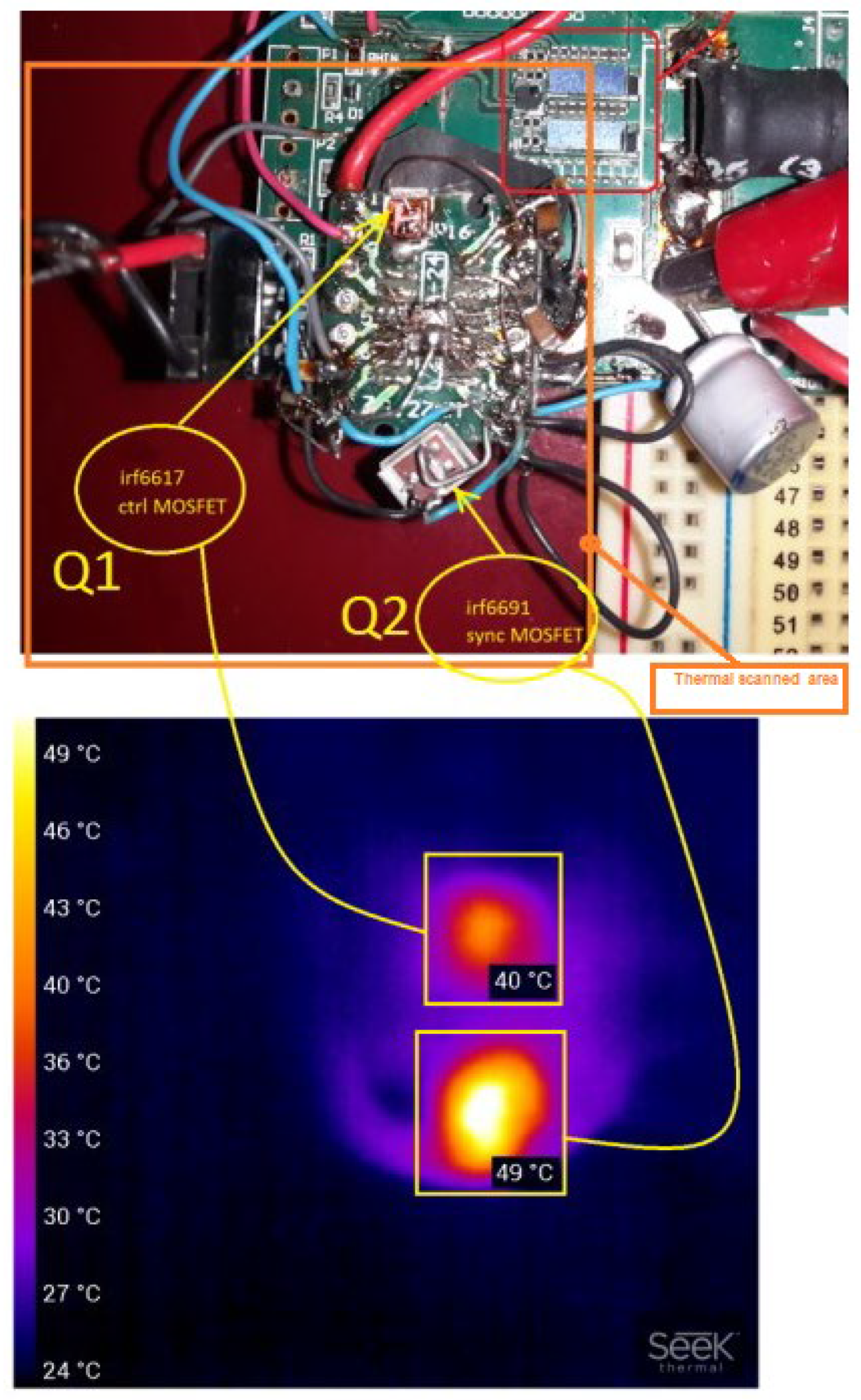
Figure 3.
Converter under investigation schematic. High fidelity dedicated SPICE model provided by the manufacturers was used.
Figure 3.
Converter under investigation schematic. High fidelity dedicated SPICE model provided by the manufacturers was used.
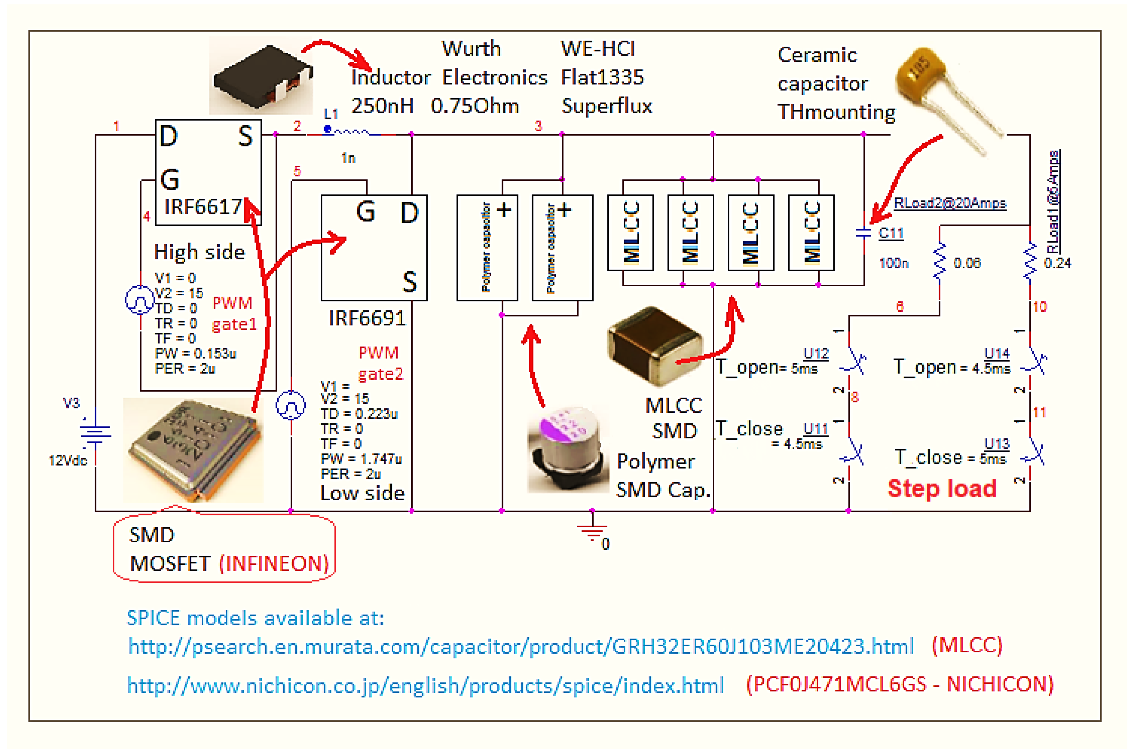
Figure 4.
Capacitor bank’s MTBF comparison resulting from calculation of the two standards.
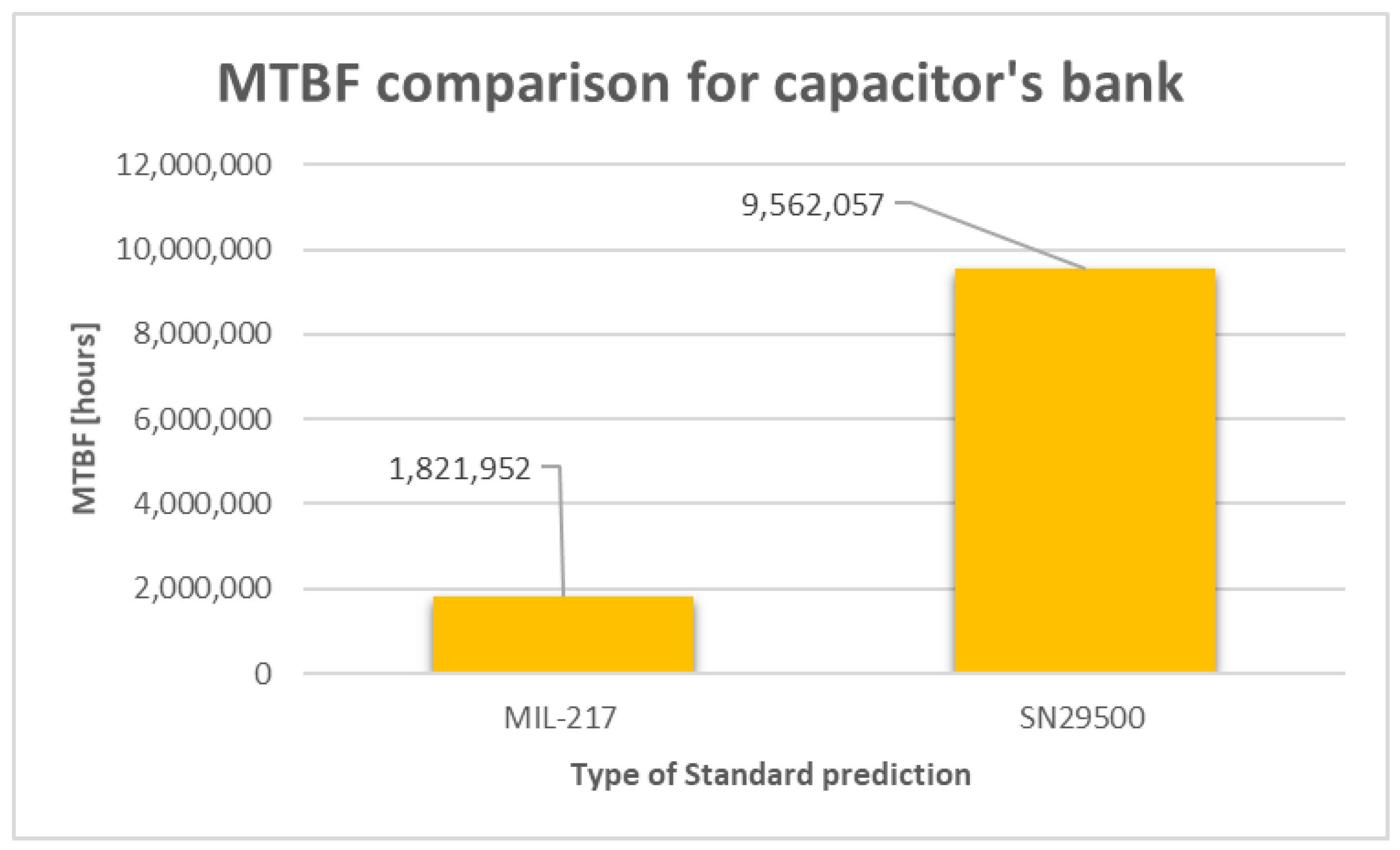
Figure 5.
Entire converter’s MTBF comparison resulting from calculation of the two standards.
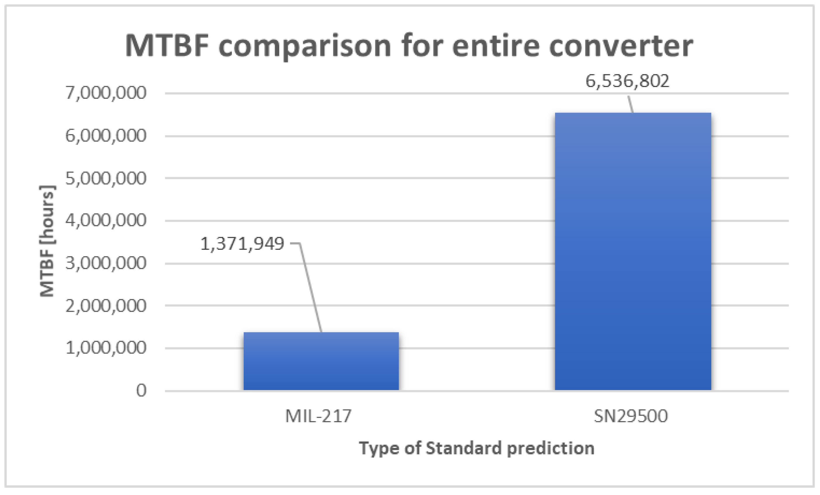
Figure 6.
Distribution of failure rates by components of the converter for MIL-217 Standard.
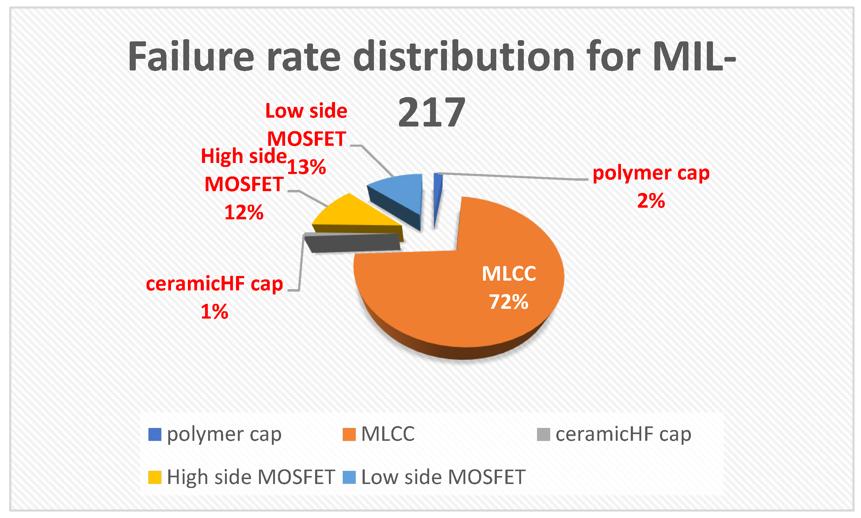
Figure 7.
Distribution of failure rates by components of the converter for SN 29500 Standard.
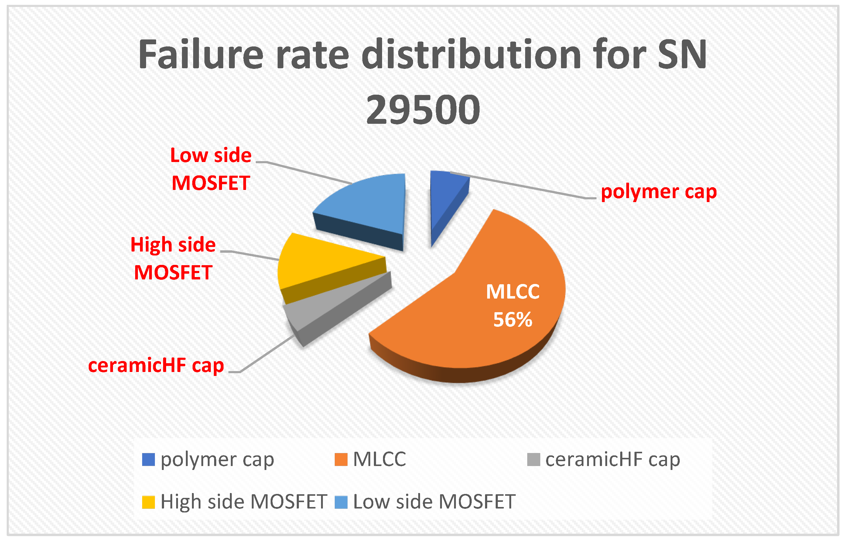
Table 1.
Elected parameters for the converter under study.
| Parameters of convertor | Value |
|---|---|
| Rated output active power, Po | max. 0.06 Ω ×25 Amp = 37.5 W |
| Input voltage, Vin | 12 V DC with 5% tolerance |
| Output voltage, Vout | 1.2 V DC ± 50 mV |
| Switching frequency, fsw | 500 khz @ Duty cycle = 7.65 % |
| Inductor, L | 250 nH / 0.75 Ω, flat 1335, superflux |
| Output capacitor bank, C | Polymer Electrolytic: 2 pcs. × 470 μF [13] MLCC: 4 pcs. × 100 μF [14] HF-through hole ceramic: 1pcs. × 100 nF HF ceramic: 1 pcs. × 100 nF |
| High side (control) MOSFET | IRF 6617, R(DS)on = 6.2 mΩ, Coss = 430 pF, Rth(J-C) = 20 °C/W [15] |
| Low side (synchro) MOSFET | IRF 6691, R(DS)on = 2.5 mΩ, Coss = 2070 pF Rth(J-C) = 1.4 °C/W [16] |
| Transient load current step | Current variation between : I down = 5A, I up = 25A |
| Ambiant temperature | 27 °C |
Table 2.
MOSFET technologies, role, type and detected temperature by IR scanning (also see Figure 2).
Table 2.
MOSFET technologies, role, type and detected temperature by IR scanning (also see Figure 2).
| MOSFET transistor | Capsule’s Temperature |
|---|---|
| Q1: High side (control) MOSFET IRF6617 | 40 °C |
| Q2: Low side (synchro) MOSFET IRF6691 | 49 °C |
Table 4.
Elected parameters for the converter under study.
| Component or device | λ MIL-217 [FIT] | πT MIL-217 | πT SN29500 | λ SN29500 [FIT] | MTBF MIL-217 [h] | MTBF SN29500 [h] |
|---|---|---|---|---|---|---|
|
2×polymer electrolytic SMD PCF0J471MCL6GS – Polymer electrolytic SMD Can-type |
15.334 | NA | 0.542388224 | 11.23 | ||
|
4×MLCC SMD GRM32ER60J107ME20 – MLCC, SMD - Class II (X7R) |
525.89 | NA | 0.712242068 | 85.5 | ||
| 1×ceramic through hole HF | 7.666 | NA | 0.542388224 | 7.85 | ||
|
Entire capacitors bank (2×polymer)‖(4×MLCC) ‖(1×ceramic through hole HF) |
1,821,952 h | 9,562,057 h | ||||
|
High side (control) MOSFET IRF6617 |
84 | 2 | 0.092 | 18.4 | ||
| Low side (synchro) MOSFET IRF6691 | 96 | 4.9 | 0.15 | 30 | ||
|
Entire converter Capacitor bank + MOSFETs |
1,371,949 h | 6,536,802 h | ||||
Disclaimer/Publisher’s Note: The statements, opinions and data contained in all publications are solely those of the individual author(s) and contributor(s) and not of MDPI and/or the editor(s). MDPI and/or the editor(s) disclaim responsibility for any injury to people or property resulting from any ideas, methods, instructions or products referred to in the content. |
© 2024 by the authors. Licensee MDPI, Basel, Switzerland. This article is an open access article distributed under the terms and conditions of the Creative Commons Attribution (CC BY) license (http://creativecommons.org/licenses/by/4.0/).
Copyright: This open access article is published under a Creative Commons CC BY 4.0 license, which permit the free download, distribution, and reuse, provided that the author and preprint are cited in any reuse.


