
Submitted:
25 June 2024
Posted:
26 June 2024
You are already at the latest version
Abstract
In the last decade, a higher level of reliability became a compulsory demand when it comes to modern DC-DC converters. This work addresses the main reliability metrics: the failure rate λλ and MTBF of an output capacitor bank used within a high current low voltage buck converter due to many studies have shown that the output capacitor bank was demonstrated being the most critical component within the converter. Many authors treated this issue, usually by doing reliability predictions. The majority of the papers use only one specific Standard Prediction to solve the problem. Herein calculation was done using both the older standard MIL-HDBK-217 and the latest one Telcordia SR-332, providing a benchmark comparison between the two which is a helpful tool for the output capacitor selection in the early stage design. Military standard was well accepted for decades in order to reliability prediction even on industrial electronics and is still used today under a critical manner because no more update after the latest version MIL-HDBK-217F - Notice 2 released in 1995. Since then, newer prediction standards had appeared in the electronics reliability market. Over time, this standard was mostly used but it does not accurately model the reliability because lack of taking account of mission profile. The above-mentioned newer standard – i.e., Telcordia SR-332 is trying to compensate also the lack of the newest component technology in the older standard (which is the first standard released on the market) supplying useful design data for design engineers who use the so-called “design with the reliability in mind” concept. Within the paper were established the environmental condition for the passive components by means of a PoL (Point of load) buck converter that is used for both calculation methods. The influence of temperature and several specific concepts like reference conditions, operating conditions, ripple, and internal self-heating were taking account in order to display the results. The temperature for the capacitor’s capsule needed in πT stress factor calculation was derived by PSPICE simulation. High fidelity and dedicated SPICE models provided by the manufacturer were used for MOSFETs, polymer electrolytic, and MLCC capacitors that compose the converter.
Keywords:
polymer electrolytic capacitor
; prediction standard
; reliability
; MTBF
1. Introduction
If we take in to account the current concepts like
Decarbonization, Industry 4. 0, Sustainable Energy or Green Transition that are
very visible today [1] we must think more and
more seriously about reliability. They can be guaranteed by a good reliability,
especially the one aimed at the power supply sources. The reliability of the
electronic circuits that make up any computing, telecommunications or
automotive equipment requires a revision of the design mindset. In the last
decade, the so-called concept of “designing with the reliability in mind”
appears more and more often. An increased reliability of electronic equipment
leads to a correct realization of the concepts we were talking about at the
beginning of the chapter. Also, high reliability is a way to compensate for an
unwanted but real phenomenon (which ruins the realization of any new project or
any maintenance operation) that appeared after the pandemic period - shortage
of component supplying.
On the other hand, more and more companies
producing electronic components and devices (especially those in the power
electronics subdomain) are starting to introduce a reliability chapter in the
data sheet for the product in question, in response to the increasing demand
from designers and end users of electronic parts of data about the reliability
of the purchased product.
But how can you create a satisfactory picture about
the reliability of a product in the shortest possible time and which is also
“reliable”? It would seem that the most accessible and unanimously accepted
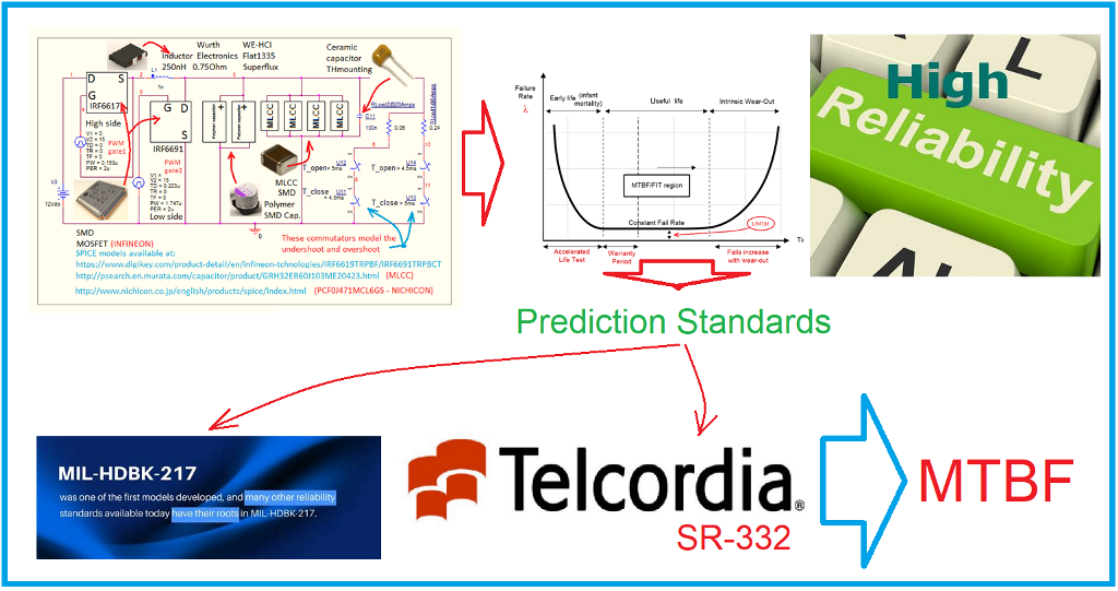
method is the use of reliability prediction standards [2,3].
2. Brief Math Presentation of the Reliability Concept
This A very well accepted definition of Reliability
looks like this: the ability of an item like part, device, or component to
perform a specific function under given conditions but in a specific period of
time. Often this period of time is expressed by correlation with the failure
rate λ:
R(t) = e -λt
The frequency of the component’s failures is
represented by the symbol λ (greek letter Lambda) named failure rate.
The frequency of the component’s
failures is represented by the symbol λ (greek letter
Lambda) named failure rate.
More and more frequently a more practical and
commercial way to express reliability is Mean Time Between Failure (MTBF) or
MTTF (Mean Time To Repair) for non-repairable systems. Thus, MTBF for example, specifies how often a unit (part, component, device) fails as a
statistical average. Or the average length of time before the first
failure appears after it starts to work, then the item no longer able to
continue functioning in normal operation.
This situation is mathematically expressed by mean
of the below integral
Or we could write a more straightforward form like:
MTBF = 1/ λ
If we choose the specific moment of
time t = 1/λ, such that
R = 1/e = 0.367
we could say that the mathematical
mean of R(t) represent the amount of time that should elapse until the
first failure occurs. Or, in other words, only 37% of the items within a
large group will last as long as the MTBF number.
Or we could see this as the device
will work properly for as long as it’s MTBF figure, with a 36.7% of confidence
level
[4–7]
.
Failure rate λ means the intrinsic
failure rate, i.e., excluding early failures and wear-out failures.
It is assumed as constant value during the lifetime (useful life or service
lifetime) period as we can see in the so called bathtub curve
[8]
(
Figure 1
) in which we can
distinguish three regions over time:
- Early life failures - characterized by a relatively higher initial failure rate, which reduces rapidly. Early-life failures are primarily caused by manufacturing defects that are not effectively screened. Defects will always occur.
- Useful (normal) life failures - is the region of the bath tub curve where the failure rate is relatively low and constant. This failure rate is quantified in units of Failure In Time (FIT) – which is an estimate of the number of failures that could occur in a billion (i.e.,109) cumulative hours of the product’s operation.
- Intrinsic wear-out - is a period of the product’s lifecycle when intrinsic wear-out dominates and failures increase exponentially. The end of a product’s useful lifetime is specified as the time of onset of wear-out. These types of failures are caused by well-known factors such as channel-hot-carrier effects, electromigration, time-dependent dielectric breakdown and negative bias temperature instability [9]. Usually there are two units of measure for its expression is:
- [F/106 h], which stands for failures per one million component -hours
- [FIT], which stands for failures in time (that is one failure per one billion component-hours)
* the latter is mainly used by component manufacturers and they use it in catalogs, application notes, etc.
The useful life period represents the segment of time during which failures occur randomly (this leading to λ = constant). Therefore, all the reliability prediction standards must provide a constant failure rate for the system’s components during the lifetime. In practice, are rather preferred specifications in MTBF, because the failure rate λ is given in 1 failure / hour (one failure per hour) which is a smaller value (as is the ‘‘failure in time’’ specification: 1 FIT = 1 failures / 109 hour), whereas the MTBF uses the unit of hours. A matter of nuance must be clarified from the start, that as there is no direct connection (or correlation) between the notion of useful life and the notion of MTBF. For the non-specialist engineers, these notions are very often confounded or mixed in. The truth is that both concepts are different but either are compulsory to describe the reliability as a well presented whole. But the thing they have in common and which makes both decreases is the temperature.
3. PSPICE Simulation for Determining the Capacitor’s Temperature
In order to determining the capacitor’s temperature (which will be required for the πT stress factor calculation) several methods are used by the engineers. In this paper, the PSPICE simulation-based method is chosen.
A buck synchronous circuit with parameters synthetized in Table 1 was elected for the reliability calculation of the DC-DC converter’s output capacitor bank.
In order to place ourselves within the latest technologies for the component parts of the converter, it was made with two MOSFET transistors in silicon technology - IRF6617 [10] was chosen as the drive transistor and IRF6691 [11] - Infineon as the sync transistor. These transistors are RoHS Compliant, Lead-Free (Qualified up to 260°C Reflow), are very suitable for application in DC-DC converters, have low conduction losses, high dv/dt immunity and low profile (< 0.7mm). Construction is type Dual Sided Cooling Compatible with existing Surface Mount Techniques.
The capacitor bank was composed of capacitors in currently used technologies - polymer aluminum can-type vertical: PCF0J471MCL6GS - manufacturer Nichicon [12]. Capacitance 470 uF at voltage rating: 6.3 Volts-DC, Tolerance 20 %, ESR: 18 mΩ - MLCC (Multi-layer ceramic capacitor) GRM32ER60J107ME20, SMD - Class II -X5R (EIA) -1210 inch package code (3225 mm), capacity of 100μF at voltage rating: 6.3 Volts,DC [13]. MLCC have the bigger ESR of all capacitors and behave very well with frequency. Polymer capacitors have greater volumetric efficiency. Conductive Polymers are used in Aluminum Capacitors to replace the wet electrolyte. These Capacitors have much lower ESR and don’t dry out over time. In order to meet the high frequency (HF) work requirements, a 100 nF through hole ceramic capacitor was added in parallel to this bank. All converter’s components are automotive qualified. The complete diagram of the buck converter used in the PSPICE simulation is shown in Figure 2.
For the simulation, precise, dedicated models, provided by the manufacturer, were used both for MOSFET transistors and for polymer electrolytic capacitors and MLCC [14,15,16]. This gives the results obtained for the temperature of the capacitors a better approach to reality and increased precision. To simulate the step-load effect (which generates overshoots and undershoots in the form of a wave at the output of the converter), use switches from the SPICE library.
As it is well known, the ripple current is defined as RMS value of the current which is flowing into the capacitor and out of the capacitor each time the switch state turns ON and OFF.
We start from the fact that the current ripple flows through the so called ESR -equivalent series resistance within the capacitor, hence it will dissipate power as given by the well-known formula for power, i.e.,:
Some combinations of N = 1÷3 aluminum polymer can-type SMD electrolytic and M = 1÷6 MLCC – SMD type capacitors are considered in [15]. Each capacitor’s current ripple was measured with PSPICE at a maximum load current where the ripple yields the highest value. The results are sown that if using more than four ceramic capacitors, the number of electrolytic capacitors does not influence the current ripple.
Among various choices, the optimized and specific calculation refers to an optimal combination of two electrolytic and four ceramic; one piece of HF ceramic capacitor THD (through hole mounting) was added in parallel for a better behavior at high frequencies. It must be said that ESR could be dependent on temperature but also on switching frequency. But that will be the subject of a future study. From [14] the simulation of the circuit gives a 2A intensity of the ripple current; so, the temperature change of the GRM32ER60J107ME20 ceramic MLCC capacitors packaged in SMD 1210 style, results (for ambient temperature Tamb = 27 °C):
Rthermic represents the thermal resistance in °C per Watt and ΔT is the allowable temperature rise of the capacitor under test i.e., the temperature difference between capacitor and ambient environment.
and the temperature change for the PCF0J472MCL6G aluminum polymer can-type SMD capacitors packaged in SMD V- style with 6A intensity of the current ripple, results (for ambient temperature Tamb = 27 °C):
4. MIL-HDBK-217-F Prediction Standard, Brief Presentation, Discussion and Reliability Calculation According to It
The United States Navy’s failure rate prediction of electronic components standard - Military Handbook 217 [17] – which was published 1965 and was widely accepted as the “Bible” of engineers involved in electronics reliability prediction. It has well international acknowledgement among specialists. This is still used today under critical manner because no more update after its latest version MIL-HDBK-217F - Notice 2 released 1991 (see Figure 3). Several experienced well-known manufacturers shown concern about the values used of this standard for failure rates, which are considered too conservative versus the ones within Telcordia SR-332 standard. This latter, are based on values from a spread range of industrial experience, which are close to reality. This is the reason for using it’s latest release in 2016 [18] which was used for calculation and to made a comparison with military standard.
4.1. How MIL-HDBK-217standard Do the Reliability Calculation
Usually, the reliability of a DC-DC converter is predicted by considering the reliability of the sum of its components. This method is often named as ‘‘parts count’’ reliability prediction [19]. Then, when the power electronic product has been designed and component stresses can be measured or calculated will be the moment when a more precise ‘‘parts stress reliability prediction’’ can be well established. The failure rate data should be obtained from the field, if we speak ideally. Mostly used for decades this standard does not accurately model the reliability because lack of taking account of mission profile [20]. In this paper it is considered for comparison the reliability calculus within [14,15] which was focused on the output capacitor bank’s failure rate calculation according to MIL-HDBK-217 rev.2 cap.10.1. So, we will use the schematic for the converter the schematic from above mentioned paper where PSPICE simulation was done for multiple-constraint choice of capacitor bank (Figure 2) with the same parameters (Table 1).
Failure rate prediction uses the reference conditions (parts count). Relationship for failure rate of electrolytic and ceramic capacitors is stated within standard as follow:
and the failure rate for equipment under reference conditions is calculated as follows:
where λref is the failure rate under reference conditions and n is the number of components. The reference conditions adopted need to be typical for the majority of applications of components in convertor and they include statements concerning:
λcapacitor-MIL-HDBK-217 = λbase ×πT × πQ × πV × πSR × πE × πC
- operating phase
- failure criterion
- mode of operation (continuous or intermittent)
- mechanical stresses
- electrical stresses
- climatic stresses
It is assumed that the failure rate used under reference conditions is specific to the component, which means it includes the effects of:
- technology of packaging
- different manufacturers from
- manufacturing process
- complexity
Data sources used should be the latest available that are applicable to the power electronic product and its specific conditions for use.
4.2. Reliability Calculation for the Converter under Test
DC-DC converter under test in this paper consists in a buck converter having a series structure from a reliability calculation point of view, so, it will be used the parts count method. Thus, the overall system failure rate became the sum of all components’ failure rate:
Equation (9) illustrates the total failure rate [15] with N = total number of components and λi = the failure rate for ith component.
According to parameters of the converter from Table 1 and taking in to account the three technology types for capacitors used in the converter under test, calculation done in [15] has delivered the following results:
λ [polymer electrolytic capacitor V-SMD -MIL-HDBK-217] = 0.007667 [F/106 h] or 7.667 [FIT]
(for 2 parts in parallel we have 0.015334 or 15.334 [FIT])
λ [MLCC capacitor MLCC SMD1210 package-MIL-HDBK-217] = 0.131475 [F/106 h] or 131.47 [FIT]
(for 4 parts in parallel we have 0.5259 [F/106 h] or 525.9 [FIT])
(14)
and for the entire bank:
λ [ceramic HF capacitor TH-MIL-HDBK-217] = 0.007666 [F/106 h] or 7.666 [FIT]
(for only 1 part)
λ [entire capacitor bank -MIL-HDBK-217] = (10) + (11) + (12) = 0.5489 [F/106 h]
or 548.9 [FIT], (2×polymer-SMD+4×MLCC-SMD+one ceramic HF)
MTBF[entire capacitor bank -MIL-HDBK-217] = 1,821,826 [hours]
If we take this latter result at a glance, it might seem to be very big (i.e., 1,821,826 hours). But, do not forget that MTBF is a statistical number and more important, this isn’t equal to useful-life (the latter being usually 10 to 15 years, depending of the manufacturer’s declaration).
5. Telcordia SR-332 Prediction Standard, Brief presentation, and Reliability Calculation According to It
Telcordia SR-332 is a reliability prediction standard that uses so called Black-Box technique [21] (also called parts count method – according to subchapter 3.1 from the standard [18]) in order to establish a reliability calculation. In this paper we consider that one part is one capacitor. The process for prediction of the steady-state failure rate for an investigated device is based on a generic steady-state failure rate for the any type of devices. This process provides methods for estimating the failure rates of electronic equipment rather for the Early Life and Steady-State periods of the equipment life cycle. The methods do not cover the Wear-Out period of the life-cycle; it is assumed that the equipment has not entered the Wear-Out phase of its life cycle – for details please see the content of the reliability standard. Then, the generic value is modified for:
- Quality
- Stress
- Temperature
The result is the mean black box steady-state failure rate, as follow:
λBBi = λGi× πQi × πSi × πTi
and for the standard deviation of the black box steady-state failure rate:
σBBi = σGi× πQi × πSi × πTi
where:
- the term λGi represents generic steady-state failure rate for the device i (according to Section 8 within standard).
- the term σGi represents standard deviation of the generic steady-state failure rate for device i (Section 8).
- the term πQi represents quality factor for device i (according to Section 9.3 - within standard).
- the term πSi represents electrical tress factor for device i (according to Section 9.2 - within standard) and is based on the percent electrical stress. If stress is unknown, we have use 1, which assumes a 50% electrical stress.
- the term πTi represents temperature factor that correspond to device i (according to Section 9.1 - within standard) and is based on normal operating temperature during the steady state.
If there isn’t laboratory data or field data for device under test, then, mean deviation and standard deviation of the device steady-state failure rate λSSi and σSSi both equaling the mean deviation and standard deviation of the black-box steady state failure rate [21]:
- λSSi = λBBi
- σSSi = σBBi
Reliability calculation for the output capacitor bank using Telcordia SR332 Standard is done as follow:
- Electrical stress percentage for capacitors in this standard is based on voltage, i.e., electrical stress (%) = (applied DC voltage + AC peak voltage)/rated voltage. So, we have for both capacitors MLCC and for Polymer: (1.2 0.2V)/6.3V = 22.2 % and for ceramic Th capacitor results: (1.2 0.2V)/25V = 10 %.
- πS factor for capacitor stress is taken from Table 9-2 (from Standard) and results for polymer capacitors πS= 0.32 (using curve 3), for MLCCs πS= 0.52 (using curve 7) and πS= 0.2 for ceramic TH capacitor.
- From standard’s Table 8-1 also results: λG-polymer = 0.19, λG-MLCC = 1,
σ G-polymer = 0.13, σ G-MLCC = 4.4 and the temperature factors: πT-polymer = 1.48, πT-MLCC = 0.7, πT-ceramic TH = 0.9.
The results of the calculation for the investigated PoL converter’s failure rates are as follow (according to the parameters and converter’s specs within Table 1 if using the calculated temperatures of the converter component’s capsule according to (8) and (9)):
λ[BB-polymer electrolytic capacitorSMD V-packageTelcordia SR332] = 0.19×0.9×1.4×0.32 = 0.076608[F/106 h] = 76.608[FIT], (153.216 [FIT] for two pieces)
σ[BB-polymer electrolytic capacitorSMD V-package Telcordia SR332] = 0.13×0.9×1.4×0.32 = 0.052416[F/106 h] = 52.416 [FIT]
λ[BB-MLCC capacitor SMD 1210 package Telcordia SR332] = 0.41×0.6×0.7×0.53 = 0.091266 [F/106 h] = 91.266 [FIT], (365.064 FIT for 4 pieces)
σ[BB-MLCC capacitor SMD 1210 package Telcordia SR332] = 0.19×0.6×0.7×0.53 = 0.042294 [F/106 h] = 42.294 [FIT]
λ[BB ceramic HF capacitor Telcordia SR332] = 0.1×1×0.9 ×0.2 = 0.018[F/106 h] = 18 [FIT] (one pcs.)
σ[BB ceramic HF capacitor Telcordia SR332] = 0.01×1×0.9×0.2 = 0.0018 [F/106 h] = 1.8 [FIT]
(25)
λ[BB-entire capacitor bank Telcordia SR332] =0.15321 +0. 365064+0.018 =
0.53628 [F/106 h] = 536.28 [FIT]
(2 × polymer electrolytic capacitor V-SMD, 4 × MLCC SMD1210 package and one HF ceramic capacitor TH mounting) and finally:
MTBF[capacitor bank Telcordia SR332] = 1,864,697 [h]
In Table 2 are synthetized the failure rate and MTBF values resulted from both calculations used.
6. Comparative Results
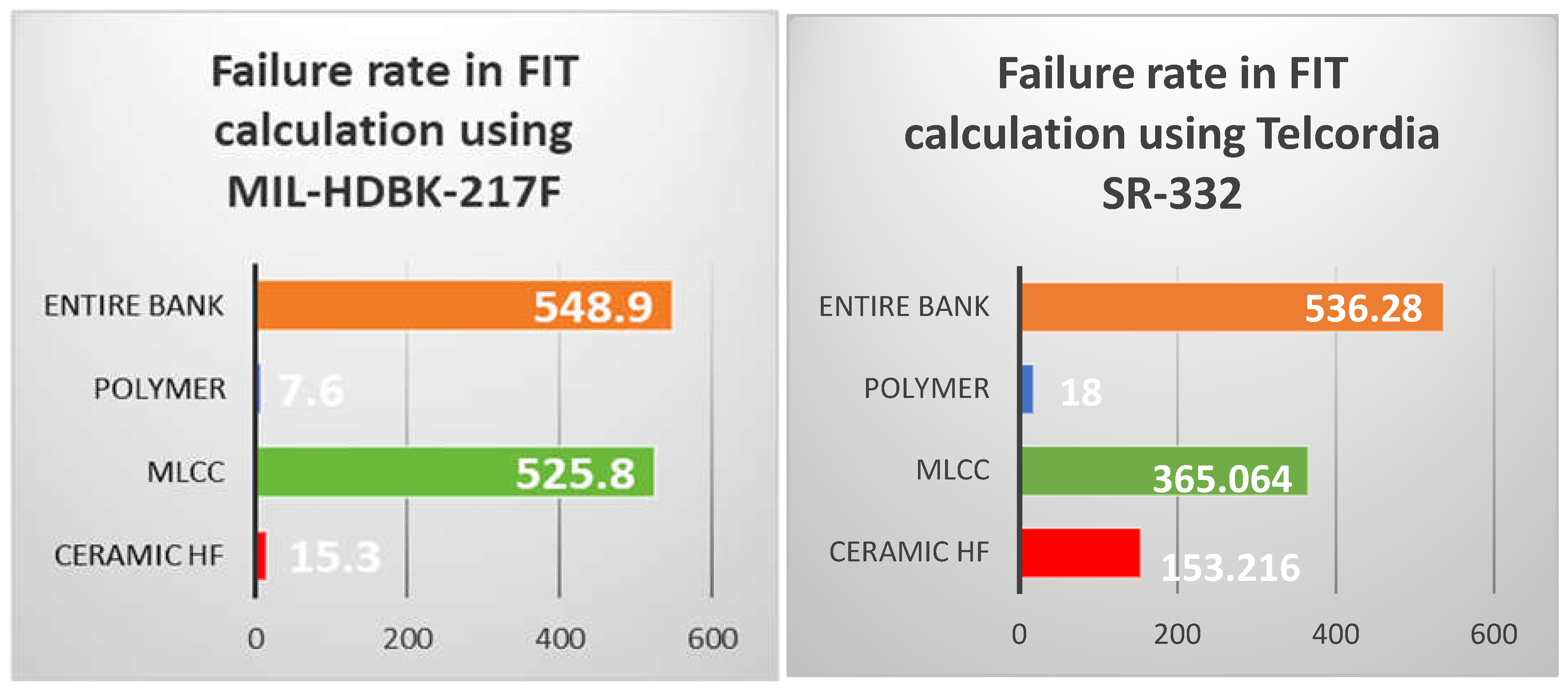
Below is the comparison of the values for failure rate and MTBF summarized in Table 2 and in Figure 3. In the table, the failure rate is measured in FIT and the MTBF is measured in hours (for the entire capacitor bank, the value in years was also shown).
Figure 4.
− Graphical comparison of the failure rate’s value using the two reliability prediction standards (the unit of measure on the horizontal axis is [FIT]).
Figure 4.
− Graphical comparison of the failure rate’s value using the two reliability prediction standards (the unit of measure on the horizontal axis is [FIT]).
7. Conclusions
The novelty provided by the work presented consists in doing the calculation of reliability using both the one that appeared first on the market, MIL-HDBK-217F and the newest one Telcordia – SR332 standard (which is mostly used by the engineers from Telecom industry) applied to a synchronous buck converter in a PoL configuration built with the newest components and using dedicated SPICE models offered by the manufacturers for simulation. MIL-HDBK-217 is more conservative and comprehensive, while Telcordia SR-332 is simpler and often yields lower failure rate predictions. The choice between them depends on the specific context and requirements of the project. SPICE simulation used for found the component’s temperature case were used in the calculation of the thermal stress factors necessary to evaluate the MTBF. Experimental results showed that calculation with MIL-HDBK-217 standard prediction gives an enhanced value of failure rate for MLCC and extremely low value for polymer capacitor. Using Telcordia standard prediction we found more balanced values. For the entire capacitor bank, the failure rate has had quasi similar values. A more functional value for the ceramic TH capacitor results in Telcordia calculation. Thus, the numbers offered by Telcordia standard seem to be more realistic.
Conflicts of Interest
The author declare no conflicts of interest.
References
- Anon., https://www.un.org/.../PB_141.pdf.
- M. G. Pecht and F. R. Nash, Predicting the reliability of electronic equipment, in Proceedings of the IEEE, vol. 82, no. 7, pp. 992-1004, July 1994. [CrossRef]
- B. Chong, “Automated CHIP MTBF Calculator,” 2022 11th International Conference on Communications, Circuits and Systems (ICCCAS), Singapore, Singapore, 2022, pp. 59-63. [CrossRef]
- W. Kanert, “Product reliability at low failure rates: Wrong expectations and real limitations,” 2012 IEEE International Reliability Physics Symposium (IRPS), Anaheim, CA, USA, 2012, pp. 5C.4.1-5C.4. [CrossRef]
- M. Krasich, “How to estimate and use MTTF/MTBF would the real MTBF please stand up?,” 2009 Annual Reliability and Maintainability Symposium, Fort Worth, TX, USA, 2009, pp. 353-359. [CrossRef]
- D. Zhou, Y. Song, Y. Liu and F. Blaabjerg, “Mission profile-based reliability evaluation of capacitor banks in wind power converters,” in IEEE Trans. Power Electron. 34 (5) 4665–4677, May 2019.
- A. B. Chong, “Automated CHIP MTBF Calculator,” 2022 11th International Conference on Communications, Circuits and Systems (ICCCAS), Singapore, Singapore, 2022, pp. 59-63. [CrossRef]
- W. S. Griffith, “Representation of Distributions Having Monotone or Bathtub-Shaped Failure Rates,” in IEEE Transactions on Reliability, vol. R-31, no. 1, pp. 95-96, April 1982. [CrossRef]
- Anon., https://www.ti.com/lit/pdf/SLOA294.
- https://www.infineon.com/cms/en/product/power/mosfet/n-channel/irf6617/.
- https://www.digikey.in/en/products/detail/infineon-technologies/IRF6691TR1PBF/1189804.
- Anon., http://www.nichicon.co.jp/english/products/spice/index.html.
- Anon., http://psearch.en.murata.com/capacitor/product/GRM32ER60J107M.
- D. Butnicu and D. O. Neacsu, Using SPICE for reliability based design of capacitor bank for telecom power supplies, 2017 IEEE 23rd International Symposium for Design and Technology in Electronic Packaging (SIITME), pp. 423-426, Constanta, 2017.
- Dan Butnicu, Dorin O. Neacsu, Using SPICE for multiple-constraint choice of capacitor bank for telecom power supplies, 2017 IEEE 23rd International Symposium for Design and Technology in Electronic Packaging (SIITME).
- Dorin O. Neacsu, Dan Butnicu, A review and ultimate solution for output filters for high-power low-voltage DC/DC converters, 2017 International Symposium on Signals, Circuits and Systems (ISSCS).
- Anon., Military Handbook - Reliability Prediction of Electronic Equipment, MIL-HDBK-217F, Notice 2, Feb 28, 1995.
- Anon., https://telecom-info.njdepot.ericsson.net/site-cgi/ido/docs.cgi?ID=SEARCH&DOCUMENT=SR-332M. G.
- R. N. S, C. A, D. Krishnachaitanya, A. M. K, S. M. S and R. W, “Reliability Analysis of PMSM Drives Processor for Commercial Electric Vehicle Utility,” 2024 Second International Conference on Emerging Trends in Information Technology and Engineering (ICETITE), Vellore, India, 2024, pp. 1-8. [CrossRef]
- D. Zhou, H. Wang, and F. Blaabjerg, Mission Profile Based System-Level Reliability Analysis of DC/DC Converters for a Backup Power Application, IEEE Trans. Power Electron., vol. 33, no. 9, pp. 8030–8039, 2018.
- R. B. Darla and C. A, “A Blackbox Failure Rate Prediction Method for Power Electronic Converters,” 2021 IEEE Madras Section Conference (MASCON), Chennai, India, 2021, pp. 1-6. [CrossRef]
- >5 A. B. Chong, “Automated CHIP MTBF Calculator,” 2022 11th International Conference on Communications, Circuits and Systems (ICCCAS), Singapore, Singapore, 2022, pp. 59-63. [CrossRef]
Figure 1.
Contribution to converter’s Failure rate from various components of a PoL converter (percentual).
Figure 1.
Contribution to converter’s Failure rate from various components of a PoL converter (percentual).
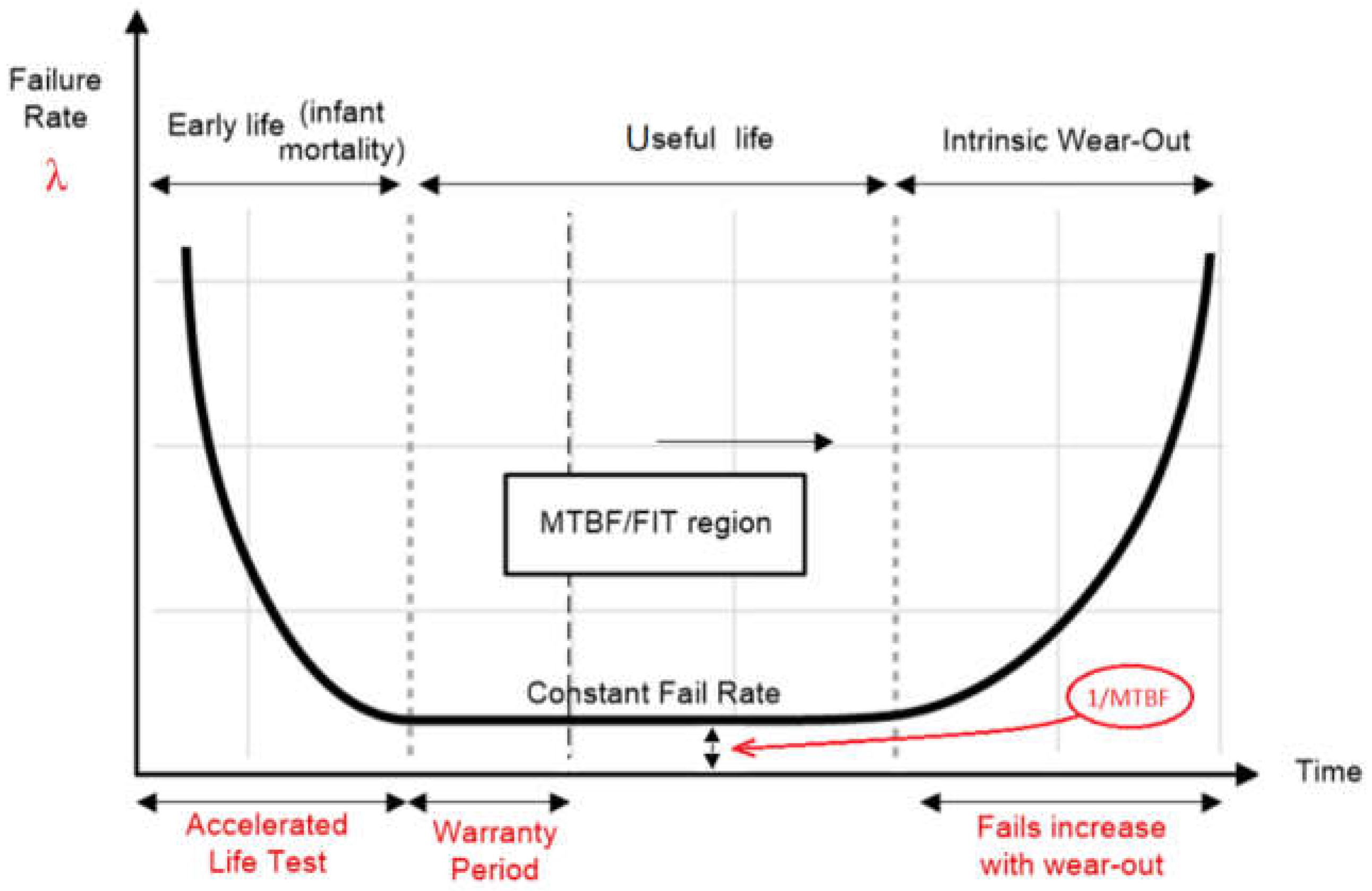
Figure 2.
Complete synchronous buck converter schematics for PSPICE simulation using dedicated models provided by the manufacturers. PWM command are modelled by Pulse sources and Step-Load variation by commutators.
Figure 2.
Complete synchronous buck converter schematics for PSPICE simulation using dedicated models provided by the manufacturers. PWM command are modelled by Pulse sources and Step-Load variation by commutators.
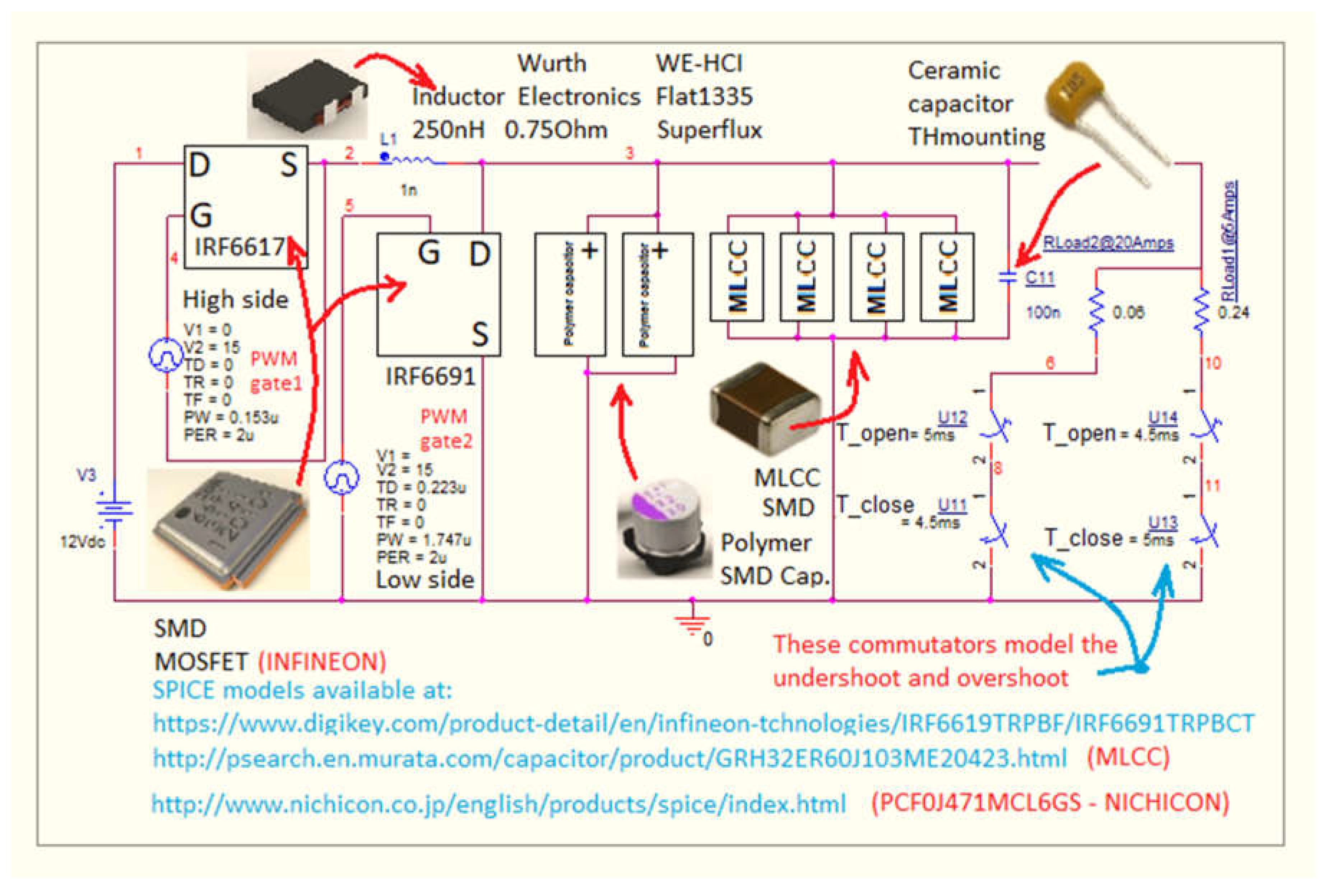
Figure 3.
− Front cover of the last MIL-HDBK-217 – Version: Revision F, Notice1 - released 2 dec1991.
Figure 3.
− Front cover of the last MIL-HDBK-217 – Version: Revision F, Notice1 - released 2 dec1991.

Table 1.
Elected parameters for the converter under study.
| Convertor’s parameters | Value |
|---|---|
| Rated output active power, Po | max. 0.06 Ω × (25 A)2 = 37.5 W |
| Load current | Iout = max. 25 A , (5A @ transition step) |
| Input voltage, Vin | 12 V DC with 5% tolerance |
| Output voltage, Vout | 1.2 V DC ± 50 mV |
| Switching frequency, fsw | 500 kHz @ Duty cycle = 7.65 % |
| Output capacitor bank, C | Polymer Electrolytic: 2 pcs. × 470 μF MLCCs: 4 pcs. × 100 μF HF-through hole ceramic: 1pcs. × 100 nF |
| Inductor, L | 250 nH, 0.75 Ω, flat 1335, superflux |
| Switching Transistors (MOSFETs) | IRF6617 (drive) and IRF6691 (sync) |
| Transient load step | Current range variation: I down = 5A, I up = 25A |
Table 2.
The resulted values for λ and MTBF.
| Capacitor’s technology | Failure rate [FIT] and MTBF [h] | |
|---|---|---|
|
λ MIL-HDBK-217 MTBF MIL-HDBK-217 |
λ Telcordia SR-332 MTBF Telcordia SR-332 |
|
| Two - polymer electrolytic (SMD) | 15.3 [FIT] 65,359,477 hour |
153.216 [FIT] 6,526,733 hour |
| Four - MLCCs (SMD) | 525.8 [FIT] 1,901,863 hour |
365.064 [FIT] 2,739,245 hour |
| One - HF ceramic (through hole) | 7.6 [FIT] 131,578,947 hour |
18 [FIT] 55,555,555 hour |
| Entire capacitor bank | 548.9 [FIT] 1,821,825 hour |
536.28 [FIT] 1,864,697 hour |
Disclaimer/Publisher’s Note: The statements, opinions and data contained in all publications are solely those of the individual author(s) and contributor(s) and not of MDPI and/or the editor(s). MDPI and/or the editor(s) disclaim responsibility for any injury to people or property resulting from any ideas, methods, instructions or products referred to in the content. |
© 2024 by the authors. Licensee MDPI, Basel, Switzerland. This article is an open access article distributed under the terms and conditions of the Creative Commons Attribution (CC BY) license (http://creativecommons.org/licenses/by/4.0/).
Copyright: This open access article is published under a Creative Commons CC BY 4.0 license, which permit the free download, distribution, and reuse, provided that the author and preprint are cited in any reuse.


