
Submitted:
09 September 2024
Posted:
10 September 2024
You are already at the latest version
Abstract
The role of coalesced bainite in hydrogen embrittlement of tempered martensitic steels was investigated. Results showed that the coalesced bainite significantly enhanced the hydrogen embrittlement resistance by restricting hydrogen accumulation at the prior austenite grain boundaries, thus shifting the hydrogen-assisted failure mode from intergranular to transgranular fracture.
Keywords:
hydrogen embrittlement
; tempered martensitic steels
; microstructure
; coalesced bainite
1. Introduction
Hydrogen is well-known for its detrimental effect on the mechanical properties of high-strength steels [1,2]. This phenomenon, known as hydrogen embrittlement, has been extensively studied over the past decades by numerous researchers [3,4,5,6,7,8,9,10,11]. The most common hydrogen embrittlement mechanisms are hydrogen-enhanced decohesion (HEDE) and hydrogen-enhanced localized plasticity (HELP) [12,13,14,15]. The HEDE mechanism demonstrates that hydrogen reduces the bonding strength between metal atoms, thereby promoting interface decohesion [16,17,18]. Local decohesion initiates cracks, mostly at the high-angle grain boundaries, which are already weakened by the presence of highly concentrated hydrogen. By contrast, the HELP mechanism focuses dislocation motion caused by hydrogen atoms near the crack tip [19,20,21,22]. The presence of hydrogen facilitates dislocation motion, thereby enhancing plastic deformation in the metal lattice.
Dislocations are critical microstructural factors that play a key role in hydrogen embrittlement. For example, Depover et al. investigated the detrimental effect of hydrogen at dislocations in Fe-C-X alloys, suggesting that mobile hydrogen trapped at dislocations significantly affects hydrogen embrittlement [21]. Momotani et al. found that a higher initial dislocation density facilitates hydrogen accumulation around the prior austenite grain boundary during the early stage of deformation in a lath martensite structure because numerous mobile dislocations can transport hydrogen [23]. In addition, hydrogen transport theory associated with dislocations has been proposed [24,25,26,27,28,29]. Hydrogen transport aided by dislocation motion accelerates hydrogen accumulation in stressed environments. Dadfarnia et al. suggested that lattice diffusion alone delivers a hydrogen concentration ahead of a crack tip that is approximately three times greater than the nominal concentration. By contrast, dislocation helps transport approximately nine times the nominal concentration for at bcc system [29]. As previously discussed, a major issue emerging from hydrogen embrittlement is the dislocation densities of microstructures. The present study aims to investigate how coalesced bainite formed during the cooling process affects the hydrogen embrittlement resistance of tempered martensitic steels.
2. Experimental Procedure
This study utilized steel with a chemical composition of Fe-0.44C-0.22Si-1.02Mn-1.15Cr-0.34Ni-0.20Mo (wt.%). The steel was austenitized at 830 ℃ for 90 min, followed by cooling at the different rates of 3.5 ℃/s, 5.3 ℃/s, and 7.5 ℃/s and then tempering at 550 ℃ for 120 min. The cooling rates were selected based on previous studies showing the phase fraction of the investigated steels in conjunction with computational thermodynamic calculation by using JMatPro® with the Fe database.
The microstructures were observed using field-emission scanning electron microscopy (FE-SEM, Hitachi SU8010, Japan). Electron backscatter diffraction (EBSD, TSL Hikari XP, USA) was performed using a SEM equipped with a TSL system with a Hikari camera at an accelerating voltage of 20 kV, a beam current of 12 nA, a scan step size of 70 nm, a specimen tilt angle of 70°, and a working distance of 15 mm. The orientation imaging software was provided by TSL (TexSEM Laboratories, Inc. Draper, USA) and used to analyze the EBSD data. Electron channeling contrast imaging (ECCI) was performed using an FE-SEM equipped with a backscattered electron (BSE) detector at an accelerating voltage of 20 kV, a beam current of 20 μA, and a working distance of 8.6 mm. X-ray diffraction (XRD, Bruker DE/D8 Advance, Bruker, Germany) was performed using a Cu Kα target (λ = 1.5405 Å). The scanning rate and range of XRD analysis were 2°/min and 40° ~ 100°, respectively. XRD peak broadening was also evaluated to investigate the dislocation density of each steel through the following Willamson-Hall equation [30]:
where β, θ, λ, ε, and D are the full width at half maximum calculated in different peaks, diffraction angle, X-ray wavelength, strain, and crystallite size, respectively. Based on the strain and crystallite size from the Willamson-Hall plot, the dislocation density ρ can be derived as follows:
where b is the magnitude of the Burgers vector.The effects of hydrogen on the tensile properties were evaluated by a slow strain-rate test (SSRT) using a universal testing machine (UT-100E, MTDI, Korea) with a capacity of 10 t. Two types of tensile specimens were machined in transverse orientation; plate type smooth (ASTM E8 1/2 sub-size, gauge length: 25.0 mm, width: 6.3 mm, thickness: 2.0 mm) [31] and round type notch (ASTM G142 standard, grip diameter: 12.7 mm, notch angle: 60°, notch radius: 0.083 mm) [32]. For the smooth tensile specimen, the strain rate was set at 5.0 × 10⁻⁵ s-1, while the crosshead speed for the notch tensile specimen was 0.015 mm/min. Hydrogen was electrochemically pre-charged into the tensile specimens in a 1 M NaOH + 3 g/L NH4SCN solution at a current density of 25 A/m2 for 24 h. Fractographic observations of the fracture surfaces of the tensile specimens were performed using SEM. Relative reduction in area (RRA) and relative notch tensile strength (RNTS) were used to estimate the hydrogen embrittlement resistance of smooth and notch tensile specimens, respectively. These hydrogen embrittlement indices were determined using the following equation:
3. Results and Discussion
Figure 1a presents the continuous cooling transformation (CCT) diagram. Bainite forms with cooling rates lower than 1 ℃/s, and the untransformed austenite decomposes into martensite. The phase fraction of bainite increases with decreasing cooling rates (Figure 1b). SEM images of the investigated steels, as shown in Figure 2a–c, reveal a tempered martensitic microstructure with dark regions. The dark regions merged into larger areas in the steels with a cooling rate of 3.5 ℃/s, whereas the regions became smaller with an increasing cooling rate. The ECCI techniques were introduced to characterize microstructural defects by channeling contrast between the grains of the steels with a cooling rate of 3.5 ℃/s [33,34,35,36,37,38]. The dark regions likely represent tempered bainite, given their lower dislocation density compared to tempered martensite (Figure 2e). The dark larger grains were coalesced bainite formed by the coalescence of adjacent small platelets during the cooling process from austenite to bainite (Figure 2f) [39,40,41,42,43,44]. Bhadeshia et al. reported that coalesced bainite tends to form at low transformation temperatures and can be found at slower cooling rates [39].
Figure 3a–d shows EBSD analytical results for the steel with a cooling rate of 3.5 ℃/s. Coalesced bainite appeared as coarse grains due to the coalescence of identically oriented fine bainite plates. In addition, coalesced bainite formed only if two adjacent platelets had identical crystallographic orientations and developed simultaneously [39,41]. This was more evident in the point-to-point misorientation and IQ value analyses, in which the line was tracked across the interface between the coalesced bainite and surrounding grains, as shown in Figure 3e,f. The coalesced bainite had higher IQ values than tempered martensite and exhibited low misorientation angles of less than 3°. Figure 4 shows XRD results for the steels under different cooling rates of 3.5 ℃/s, 5.3 ℃/s, and 7.5 ℃/s. In all samples, only the α-Fe phase was identified without detecting other phases. The dislocation density was 6.43 × 10¹⁴ /m-2, 6.66 × 10¹⁴ /m-2, and 2.12 × 10¹⁵ /m-2 for the steels under cooling rates of 3.5 ℃/s, 5.3 ℃/s, and 7.5 ℃/s, respectively.
Figure 5a shows the variations in tensile properties of the steels investigated in this study. Given that the quenched and tempered steels exhibited similar tempered martensitic microstructures, all specimens had similar tensile strengths. However, due to the presence of coalesced bainite, only the steel cooled at 3.5 ℃/s exhibited a slight 5% decrease in yield strength compared with those cooled at 5.3 ℃/s and 7.5 ℃/s [43,44]. The RRA and RNTS results are plotted in Figure 5b. Both hydrogen embrittlement resistances increased with decreasing cooling rates. This occurred because a high fraction of tempered bainite and a new generation of coalesced bainite at low cooling rates improved the hydrogen embrittlement resistance by restricting hydrogen transport with the low dislocation density.
To elucidate the effects of coalesced bainite on hydrogen embrittlement, SSRT was performed on both smooth and notched tensile specimens. The RNTS decreased only by 30.9% under cooling rates of 3.5 ℃/s to 7.5 ℃/s, whereas the RRA decreased by 79.7% in the same range. Figure 6a–d show the fracture surfaces of the H-charged specimens to determine the effects of the cooling rates and geometries of the tensile specimens on the fracture mode. The smooth tensile specimen with a cooling rate of 3.5 ℃/s exhibited a combination of quasi-cleavage and ductile fracture modes, whereas that with a cooling rate of 7.5 ℃/s showed an intergranular fracture mode where cracks were propagated along prior austenite grain boundaries. By contrast, the notch tensile specimens under cooling rates of 3.5 ℃/s and 7.5 ℃/s exhibited a combination of intergranular and quasi-cleavage fracture modes.
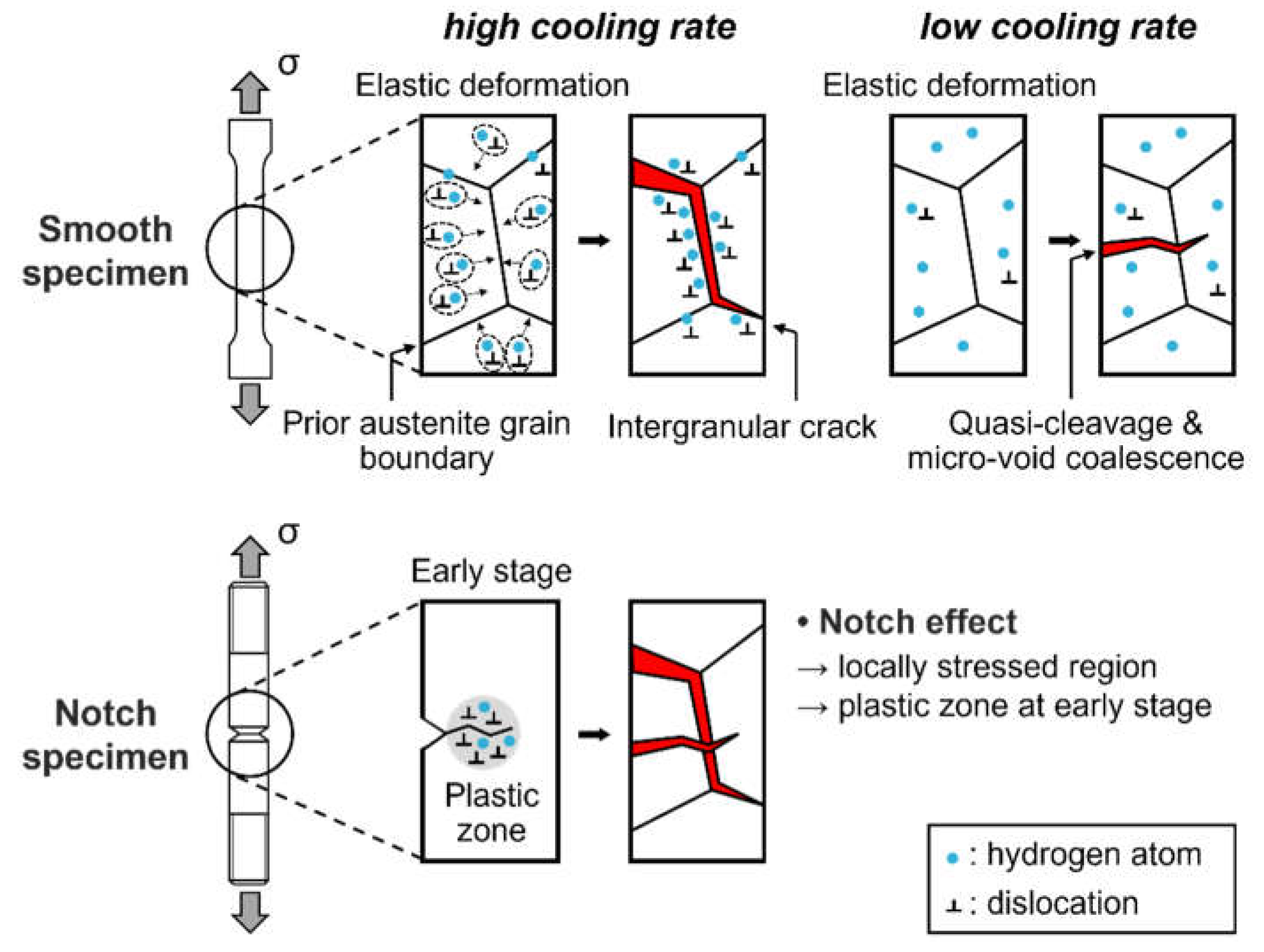
Figure 7 presents schematics showing the differences in hydrogen embrittlement behavior according to specimen geometry. For smooth specimens under tensile deformation, hydrogen atoms could migrate along dislocations and accumulate at prior austenite grain boundaries in the elastic region before yielding [23]. Hydrogen atoms accumulated at prior austenite grain boundaries can cause premature fracture through the HEDE mechanism, making the steel highly vulnerable to hydrogen embrittlement when dislocations are not sufficiently released. In smooth specimens with a high fraction of tempered martensite and high dislocation density, intergranular fractures became dominant, as shown in Figure 6b. However, hydrogen atoms became immobile in the coalesced bainite due to their large area and with relatively low dislocation density (Figure 2f), resulting in weak accumulation at prior austenite grain boundaries. This enables the smooth specimen with low cooling rates to become sufficiently elongated until it fractured in a transgranular mode consisting of dimples and quasi-cleavage, as shown in Figure 6a. Therefore, the RRA was greatly changed as the cooling rate increased from 3.5 ℃/s to 5.3 ℃/s. Accordingly, we could conclude that the formation of coalesced bainite contributed to an increase in the hydrogen embrittlement resistance of tempered martensitic steels. Interestingly, the differences in the fracture modes resulting from the cooling rate disappeared for the notch specimens. When the notch introduced triaxial stress and generated highly local stressed regions, dislocation pile-ups at the notch accelerated crack initiation at a very early stage of deformation. Because the stress concentration at the notch was dominant from the initial deformation stage, a similar fracture morphology occurred even though the initial dislocation density changed the hydrogen embrittlement resistance of the tempered martensite.
4. Conclusions
The introduction of coalesced bainite significantly enhanced the hydrogen embrittlement resistance of tempered martensitic steels. The formation of coalesced bainite with a low dislocation density impeded hydrogen transport and accumulation at prior austenite grain boundaries. Accordingly, SSRT results of the smooth tensile specimens indicated a shift from the intergranular to the ductile fracture mode. However, the effect of the cooling rate diminished in the notch tensile specimens due to the prevailing stress concentration at the notch. Overall, these findings suggest that exploring the role of coalesced bainite offers valuable insights for improving the performance of tempered martensitic steels in hydrogen-rich environments and thus warrants further investigation of microstructural alterations.
Acknowledgments
This research was supported by the Technology Innovation Program (Grant No. 20015945) funded by the Ministry of Trade, Industry and Energy (MOTIE) and by the Basic Science Research Program through the National Research Foundation of Korea (NRF-2022R1A2C2004834). The authors are very grateful to Hyun-Joo Seo and Hwan-Gyo Jung, POSCO, for providing the steels used in this study.
References
- Zielinski, A.; Domzalicki, P. Hydrogen degradation of high-strength low-alloyed steels. J. Mech. Work. Technol. 2003, 133, 230–235. [Google Scholar] [CrossRef]
- Liu, Q.; Atrens, A. A critical review of the influence of hydrogen on the mechanical properties of medium-strength steels. Corros. Rev. 2013, 31, 85–103. [Google Scholar] [CrossRef]
- Cotterill, P. The hydrogen embrittlement of metals. Prog. Mater. Sci. 1961, 9, 205–250. [Google Scholar] [CrossRef]
- Bernstein, I. The role of hydrogen in the embrittlement of iron and steel. Mater. Sci. Eng. 1970, 6, 1–19. [Google Scholar] [CrossRef]
- A Oriani, R. Hydrogen Embrittlement of Steels. Annu. Rev. Mater. Sci. 1978, 8, 327–357. [Google Scholar] [CrossRef]
- Wang, M.; Akiyama, E.; Tsuzaki, K. Effect of hydrogen and stress concentration on the notch tensile strength of AISI 4135 steel. Mater. Sci. Eng. A 2005, 398, 37–46. [Google Scholar] [CrossRef]
- Kim, S.-G.; Shin, S.-H.; Hwang, B. Machine learning approach for prediction of hydrogen environment embrittlement in austenitic steels. J. Mater. Res. Technol. 2022, 19, 2794–2798. [Google Scholar] [CrossRef]
- Yoo, I.; Lee, J.-M.; Lim, H.-S.; Suh, J.-Y.; Lee, J.; Hwang, B. Comparative Study of Hydrogen Embrittlement of Three Heat-resistant Cr-Mo Steels Subjected to Electrochemical and Gaseous Hydrogen Charging. Met. Mater. Trans. A 2020, 51, 2118–2125. [Google Scholar] [CrossRef]
- Nagumo, M. Hydrogen related failure of steels – a new aspect. Mater. Sci. Technol. 2004, 20, 940–950. [Google Scholar] [CrossRef]
- Lee, S.-I.; Lee, J.-M.; Lee, S.-Y.; Kim, H.-J.; Suh, J.-Y.; Shim, J.-H.; Baek, U.-B.; Nahm, S.-H.; Lee, J.; Hwang, B. Tensile and fracture behaviors of austenitic high-manganese steels subject to different hydrogen embrittlement test methods. Mater. Sci. Eng. A 2019, 766, 138367. [Google Scholar] [CrossRef]
- Koyama, M.; Akiyama, E.; Lee, Y.-K.; Raabe, D.; Tsuzaki, K. Overview of hydrogen embrittlement in high-Mn steels. Int. J. Hydrogen Energy 2017, 42, 12706–12723. [Google Scholar] [CrossRef]
- Lynch, S. Hydrogen embrittlement phenomena and mechanisms. Corros. Rev. 2012, 30, 105–123. [Google Scholar] [CrossRef]
- Li, X.; Ma, X.; Zhang, J.; Akiyama, E.; Wang, Y.; Song, X. Review of Hydrogen Embrittlement in Metals: Hydrogen Diffusion, Hydrogen Characterization, Hydrogen Embrittlement Mechanism and Prevention. Acta Met. Sin. 2020, 33, 759–773. [Google Scholar] [CrossRef]
- Huang, S.; Hui, H.; Peng, J. Prediction of hydrogen-assisted fracture under coexistence of hydrogen-enhanced plasticity and decohesion. Int. J. Hydrogen Energy 2023, 48, 36987–37000. [Google Scholar] [CrossRef]
- Djukic, M.B.; Bakic, G.M.; Zeravcic, V.S.; Sedmak, A.; Rajicic, B. The synergistic action and interplay of hydrogen embrittlement mechanisms in steels and iron: Localized plasticity and decohesion. Eng. Fract. Mech. 2019, 216, 106528. [Google Scholar] [CrossRef]
- Troiano, A.R. The Role of Hydrogen and Other Interstitials in the Mechanical Behavior of Metals. Met. Microstruct. Anal. 2016, 5, 557–569. [Google Scholar] [CrossRef]
- Nagao, A.; Dadfarnia, M.; Somerday, B.P.; Sofronis, P.; Ritchie, R.O. Hydrogen-enhanced-plasticity mediated decohesion for hydrogen-induced intergranular and “quasi-cleavage” fracture of lath martensitic steels. J. Mech. Phys. Solids 2018, 112, 403–430. [Google Scholar] [CrossRef]
- Dong, X.; Wang, D.; Thoudden-Sukumar, P.; Tehranchi, A.; Ponge, D.; Sun, B.; Raabe, D. Hydrogen-associated decohesion and localized plasticity in a high-Mn and high-Al two-phase lightweight steel. Acta Mater. 2022, 239, 118296. [Google Scholar] [CrossRef]
- Beachem, C.D. A new model for hydrogen-assisted cracking (hydrogen “embrittlement”). Met. Trans. 1972, 3, 441–455. [Google Scholar] [CrossRef]
- Birnbaum, H.; Sofronis, P. Hydrogen-enhanced localized plasticity—a mechanism for hydrogen-related fracture. Mater. Sci. Eng. A 1994, 176, 191–202. [Google Scholar] [CrossRef]
- Depover, T.; Verbeken, K. The detrimental effect of hydrogen at dislocations on the hydrogen embrittlement susceptibility of Fe-C-X alloys: An experimental proof of the HELP mechanism. Int. J. Hydrogen Energy 2018, 43, 3050–3061. [Google Scholar] [CrossRef]
- Martin, M.L.; Dadfarnia, M.; Nagao, A.; Wang, S.; Sofronis, P. Enumeration of the hydrogen-enhanced localized plasticity mechanism for hydrogen embrittlement in structural materials. Acta Mater. 2018, 165, 734–750. [Google Scholar] [CrossRef]
- Momotani, Y.; Shibata, A.; Yonemura, T.; Bai, Y.; Tsuji, N. Effect of initial dislocation density on hydrogen accumulation behavior in martensitic steel. Scr. Mater. 2020, 178, 318–323. [Google Scholar] [CrossRef]
- Windle, A.H.; Smith, G.C. The Effect of Hydrogen on the Plastic Deformation of Nickel Single Crystals. Met. Sci. J. 1968, 2, 187–191. [Google Scholar] [CrossRef]
- Tien, J.K.; Richards, R.J.; Buck, O.; Marcus, H.L. Model of dislocation sweep-in of hydrogen during fatigue crack growth. Scr. Met. 1975, 9, 1097–1101. [Google Scholar] [CrossRef]
- Kurkela, M.; Latanision, R. The effect of plastic deformation on the transport of hydrogen in nickel. Scr. Met. 1979, 13, 927–932. [Google Scholar] [CrossRef]
- Hwang, C.; Bernstein, I. Dislocation transport of hydrogen in iron single crystals. Acta Met. 1986, 34, 1001–1010. [Google Scholar] [CrossRef]
- Itoh, G.; Jinkoji, T.; Kanno, M.; Koyama, K. Effect of impurity hydrogen on the deformation and fracture in an Al-5 mass Pct Mg alloy. Met. Mater. Trans. A 1997, 28, 2291–2295. [Google Scholar] [CrossRef]
- Dadfarnia, M.; Martin, M.L.; Nagao, A.; Sofronis, P.; Robertson, I.M. Modeling hydrogen transport by dislocations. J. Mech. Phys. Solids 2015, 78, 511–525. [Google Scholar] [CrossRef]
- Williamson, G.K.; Hall, W.H. X-ray line broadening from filed aluminium and wolfram. Acta Metall. 1953, 1, 22–31. [Google Scholar] [CrossRef]
- ASTM E8/E8M-2013; Standard Test Methods for Tension Testing of Metallic Materials. ASTM, 2001.
- ASTM G142 Standard Test Methods for Determination of Susceptibility of Metals to Embrittlement in Hydrogen Containing Environments at High Pressure, High Temperature, or Both, 2016.
- Crimp, M.A. Scanning electron microscopy imaging of dislocations in bulk materials, using electron channeling contrast. Microsc. Res. Tech. 2006, 69, 374–381. [Google Scholar] [CrossRef] [PubMed]
- Gutierrez-Urrutia, I.; Zaefferer, S.; Raabe, D. Electron channeling contrast imaging of twins and dislocations in twinning-induced plasticity steels under controlled diffraction conditions in a scanning electron microscope. Scr. Mater. 2009, 61, 737–740. [Google Scholar] [CrossRef]
- Gutierrez-Urrutia, I.; Raabe, D. Dislocation and twin substructure evolution during strain hardening of an Fe–22wt.% Mn–0.6wt.% C TWIP steel observed by electron channeling contrast imaging. Acta Mater. 2011, 59, 6449–6462. [Google Scholar] [CrossRef]
- Yao, M.; Pradeep, K.; Tasan, C.; Raabe, D. A novel, single phase, non-equiatomic FeMnNiCoCr high-entropy alloy with exceptional phase stability and tensile ductility. Scr. Mater. 2013, 72, 5–8. [Google Scholar] [CrossRef]
- He, Y.; Jung, J.; Xu, L.; Liu, S.; Shin, K. A highly efficient and flexible route to study multi-scale microstructures in steels via BSE observation. Mater. Lett. 2022, 306, 130871. [Google Scholar] [CrossRef]
- Gao, J.; Xu, Z.; Fang, X.; He, J.; Li, W.; Du, X.; He, Y.; Jia, X.; Zhou, S. Enhancing creep resistance of aged Fe–Cr–Ni medium-entropy alloy via nano-sized Cu-rich and NbC precipitates investigated by nanoindentation. J. Mater. Res. Technol. 2022, 20, 1860–1872. [Google Scholar] [CrossRef]
- H. K. D. H. Bhadeshia, E. Keehan, L. Karlsson, H. O. Andren. Trans. Indian Inst. Met. 2006, 59, 689–694.
- Keehan, E.; Karlsson, L.; Bhadeshia, H.; Thuvander, M. Three-dimensional analysis of coalesced bainite using focused ion beam tomography. Mater. Charact. 2008, 59, 877–882. [Google Scholar] [CrossRef]
- Keehan, E.; Karlsson, L.; Bhadeshia, H.K.D.H.; Thuvander, M. Electron backscattering diffraction study of coalesced bainite in high strength steel weld metals. Mater. Sci. Technol. 2008, 24, 1183–1188. [Google Scholar] [CrossRef]
- Pak, J.H.; Bhadeshia, H.K.D.H.; Karlsson, L.; Keehan, E. Coalesced bainite by isothermal transformation of reheated weld metal. Sci. Technol. Weld. Join. 2008, 13, 593–597. [Google Scholar] [CrossRef]
- He, S.; He, B.; Zhu, K.; Huang, M. On the correlation among dislocation density, lath thickness and yield stress of bainite. Acta Mater. 2017, 135, 382–389. [Google Scholar] [CrossRef]
- Su, C.-H.; Li, Q.-G.; Huang, X.-F.; Huang, W.-G. Effect of bainite microstructure during two-step quenching and partitioning process on strength and toughness properties of a 0.3%C bainitic steel. J. Iron Steel Res. Int. 2018, 25, 235–242. [Google Scholar] [CrossRef]
Figure 1.
(a) Continuous cooling transformation (CCT) diagram of the investigated steels (M, martensite; B, bainite; A, austenite; F, ferrite; P, pearlite) and (b) the phase fraction plotted as a function of different cooling rates of 3.5 ℃/s, 5.3 ℃/s, and 7.5 ℃/s. Both phase diagrams were calculated by thermodynamic calculation software.
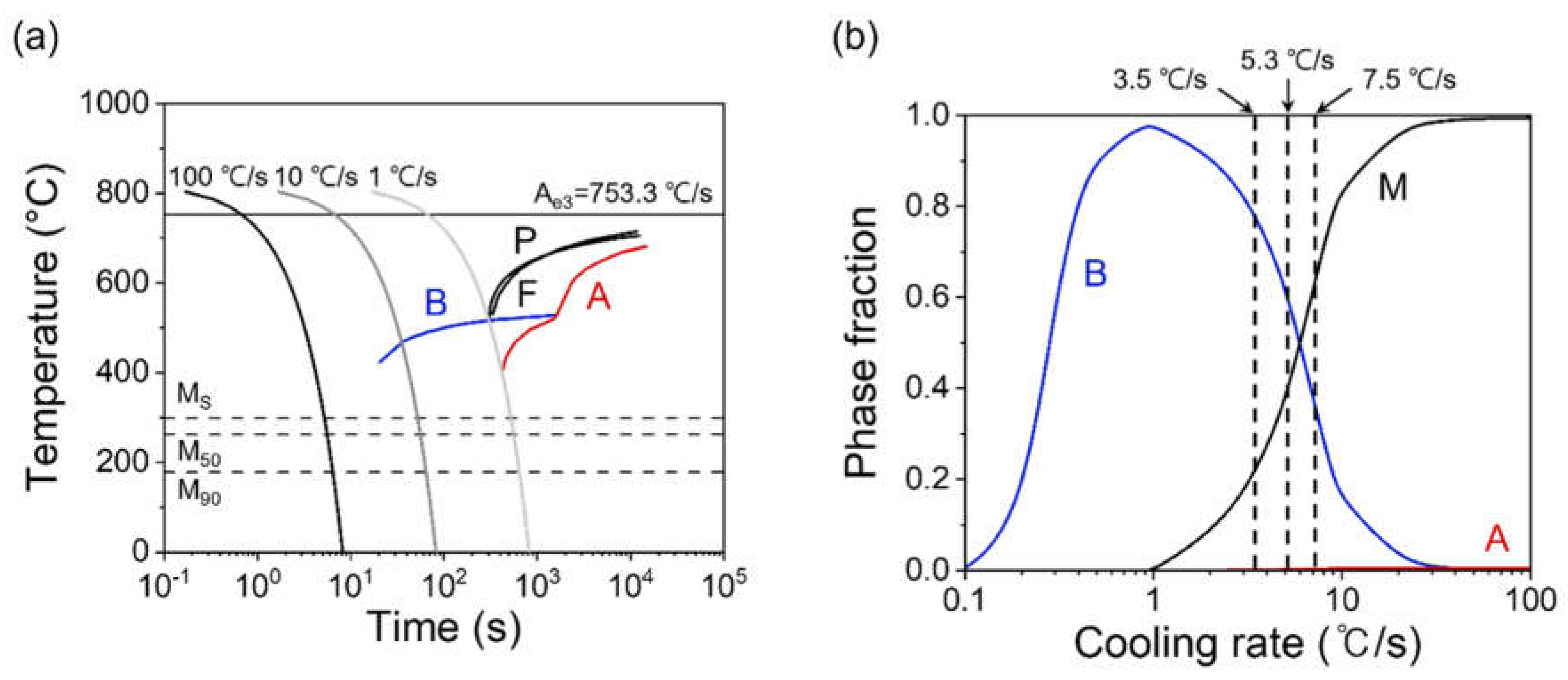
Figure 2.
SEM micrographs of the steels under different cooling rates of (a) 3.5 ℃/s, (b) 5.3 ℃/s, and (c) 7.5 ℃/s. (d) Magnified view showing coalesced bainite (CB) in the white dotted box for the (a) micrograph. (e) and (f) Electron channeling contrast imaging (ECCI) micrographs for the steels with a cooling rate of 3.5 ℃/s. TB refers to tempered bainite, and TM indicates tempered martensite.
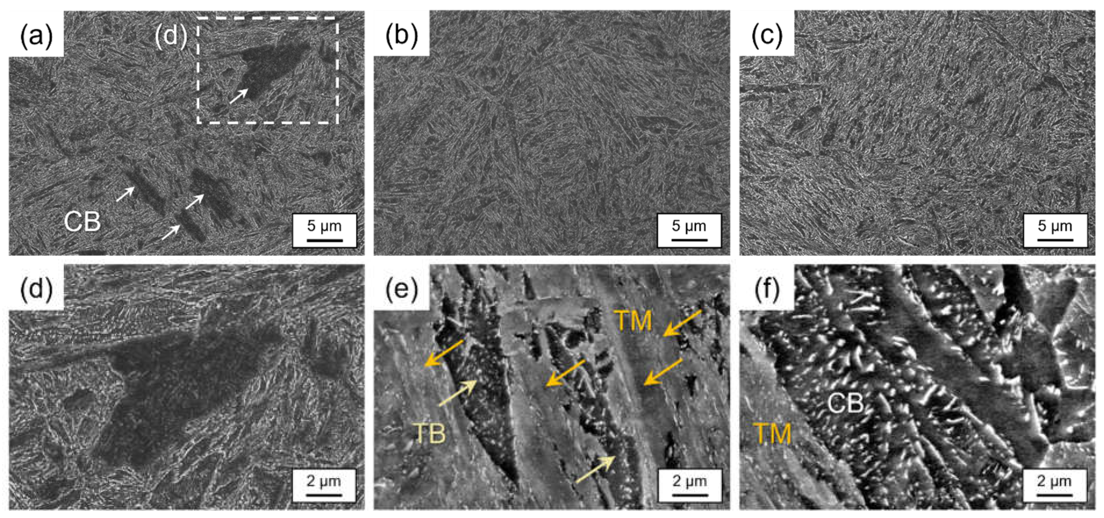
Figure 3.
(a)–(c) Inverse pole figure (IPF) and (d) image quality (IQ) maps obtained from electron backscatter diffraction (EBSD) results for the steels with a cooling rate of 3.5 ℃/s. The (b) and (c) IPF maps magnified in the (a) IPF map (TM; tempered martensite, CB; coalesced bainite, TB; tempered bainite). The (e) and (f) misorientation and image quality (IQ) value distributions of coalesced bainite (CB) relative to surrounding microstructures, which are profiled along blue arrows in (b) and (c), respectively.
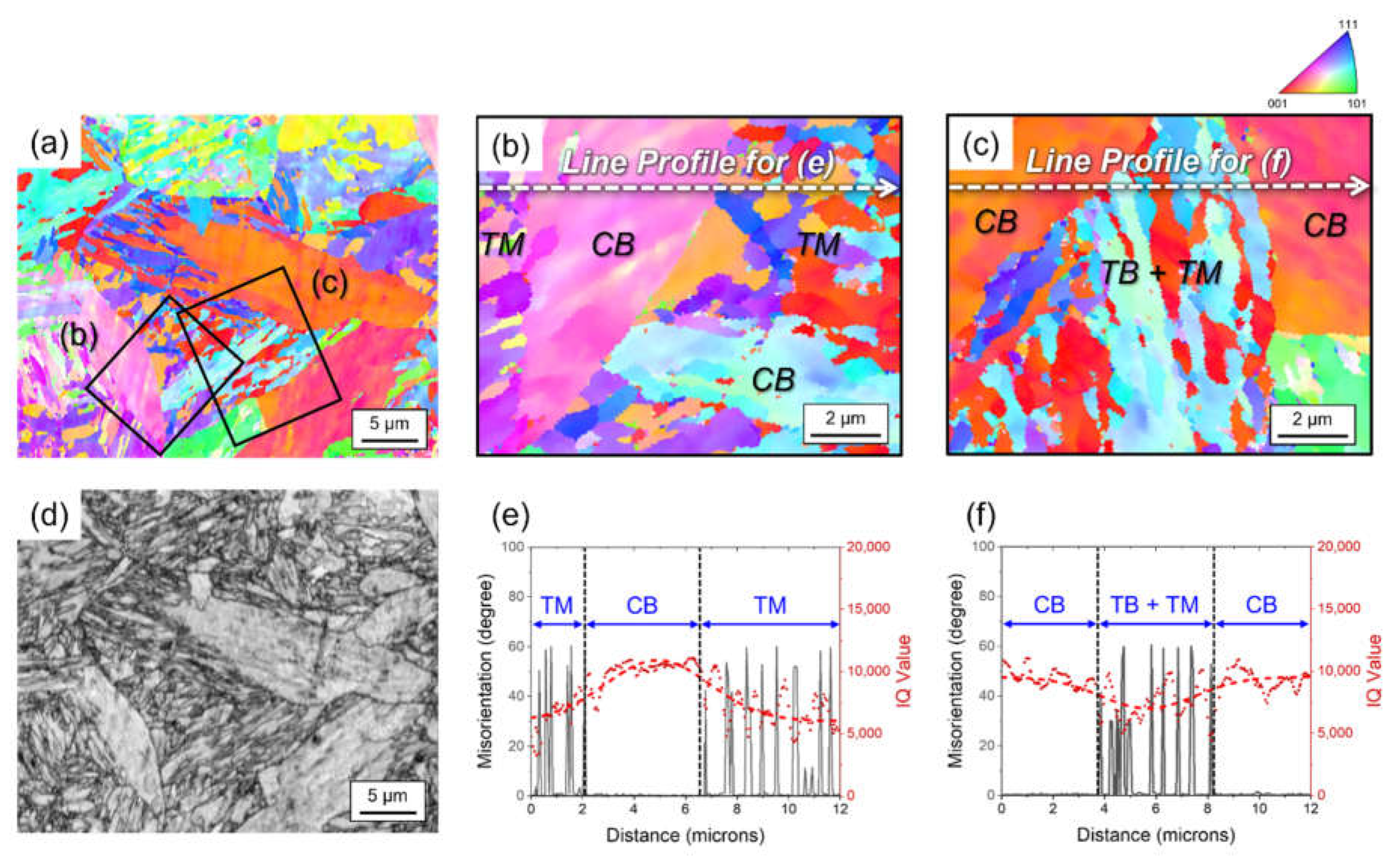
Figure 4.
(a) X-ray diffraction (XRD) profile results and (b)–(d) Williamson-Hall plots for the steels under different cooling rates of 3.5 ℃/s, 5.3 ℃/s, and 7.5 ℃/s.
Figure 4.
(a) X-ray diffraction (XRD) profile results and (b)–(d) Williamson-Hall plots for the steels under different cooling rates of 3.5 ℃/s, 5.3 ℃/s, and 7.5 ℃/s.
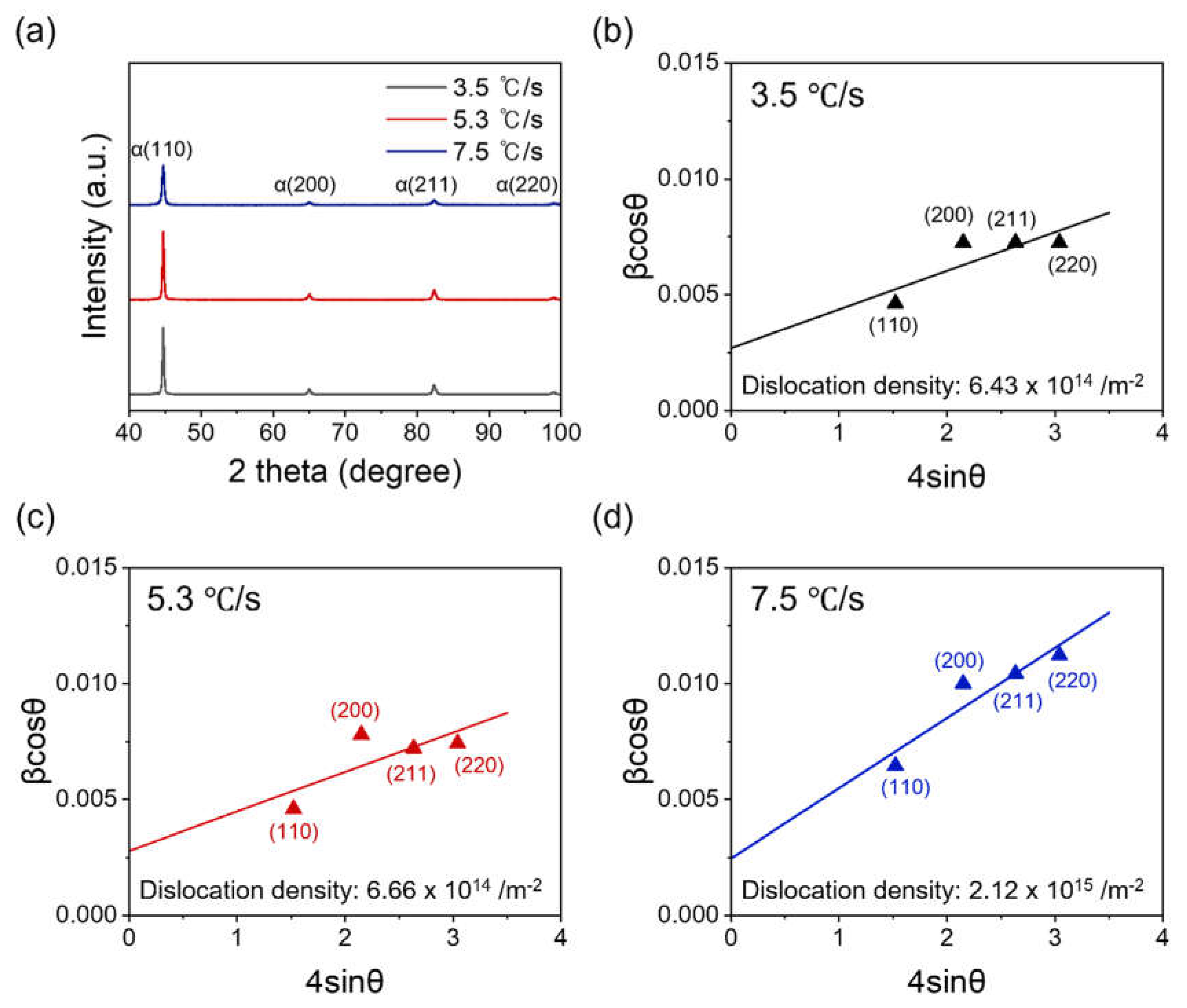
Figure 5.
(a) Variations of tensile properties and (b) relative index of hydrogen embrittlement resistance measured from the slow strain-rate test (SSRT) results for the steels under different cooling rates of 3.5 ℃/s, 5.3 ℃/s, and 7.5 ℃/s.
Figure 5.
(a) Variations of tensile properties and (b) relative index of hydrogen embrittlement resistance measured from the slow strain-rate test (SSRT) results for the steels under different cooling rates of 3.5 ℃/s, 5.3 ℃/s, and 7.5 ℃/s.
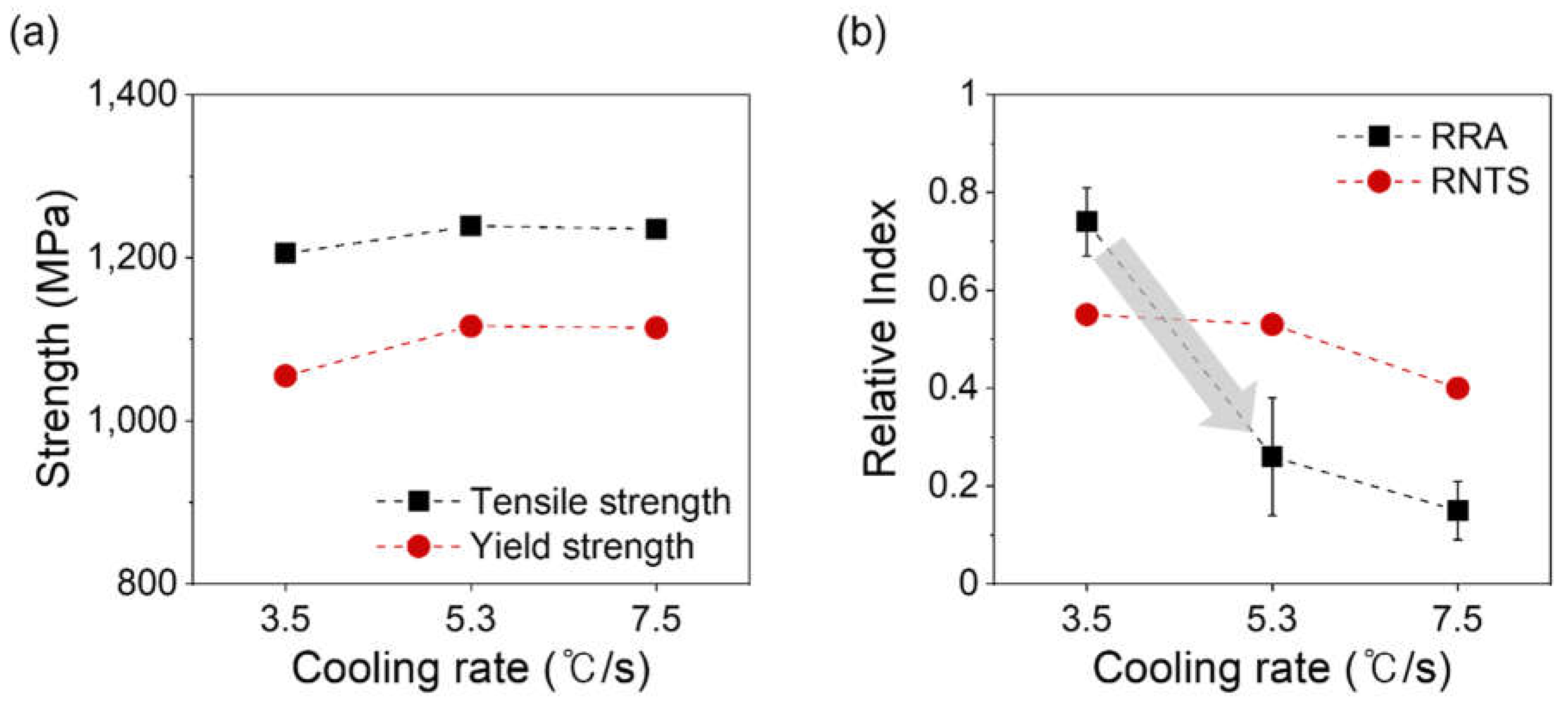
Figure 6.
SEM fractographs of the H-charged tensile specimens of (a) and (b) smooth, and (c) and (d) notch for the steels under different cooling rates of (a) and (c) 3.5 ℃/s, and (b) and (d) 7.5 ℃/s.
Figure 6.
SEM fractographs of the H-charged tensile specimens of (a) and (b) smooth, and (c) and (d) notch for the steels under different cooling rates of (a) and (c) 3.5 ℃/s, and (b) and (d) 7.5 ℃/s.
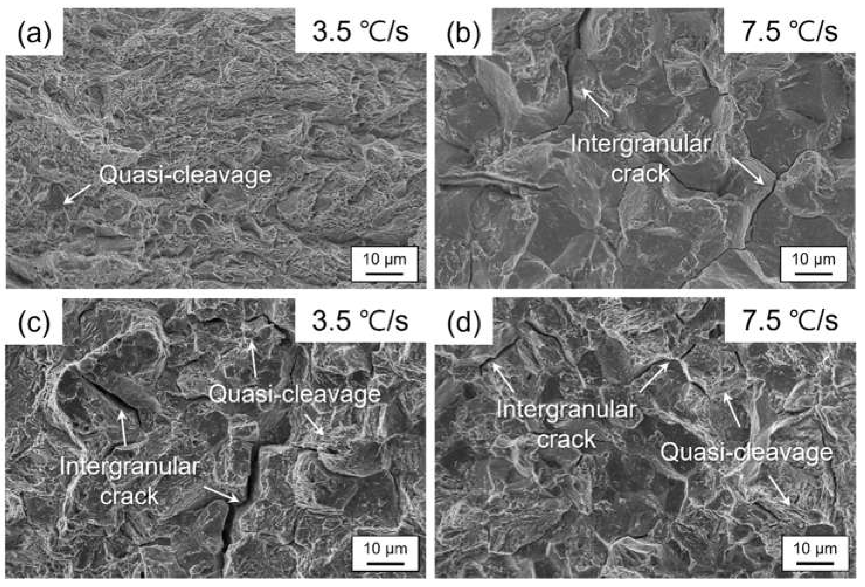
Figure 7.
Schematic illustration explaining the fracture mechanism of the smooth and notch tensile specimens.
Figure 7.
Schematic illustration explaining the fracture mechanism of the smooth and notch tensile specimens.
Disclaimer/Publisher’s Note: The statements, opinions and data contained in all publications are solely those of the individual author(s) and contributor(s) and not of MDPI and/or the editor(s). MDPI and/or the editor(s) disclaim responsibility for any injury to people or property resulting from any ideas, methods, instructions or products referred to in the content. |
© 2024 by the authors. Licensee MDPI, Basel, Switzerland. This article is an open access article distributed under the terms and conditions of the Creative Commons Attribution (CC BY) license (http://creativecommons.org/licenses/by/4.0/).
Copyright: This open access article is published under a Creative Commons CC BY 4.0 license, which permit the free download, distribution, and reuse, provided that the author and preprint are cited in any reuse.


