Submitted:
28 August 2024
Posted:
28 August 2024
You are already at the latest version
Abstract
An efficient cooling system is necessary for the reliability and safety of the modern microchips for longer life. As microchips become smaller and more powerful, the heat flux generated by these chips per unit area also rises sharply. Traditional cooling techniques are inadequate to meet the recent cooling requirements of microchips. To meet the current cooling demand of Microelectromechanical devices (MEMS) devices and microchips, microchannel heat sinks (MCHS) technology is the latest invention that can dissipate a significant amount of heat because of its high surface area to volume ratio. This study provides a concise summary of design, material selection, and performance parameters of MCHS that are developed over the last few decades. The limitations and challenges associated with different techniques employed by researchers over time to enhance the thermal efficiency of microchannel heat sinks are discussed. The effects on the thermal enhancement factor, Nusselt number, and pressure drop at different Reynold numbers, in passive techniques (flow obstruction) i.e. ribs, grooves, dimples, and cavities change in curvature of MCHS are discussed. This study also discusses the increase in heat transfer using nanofluids and how change in coolant type also significantly affects the thermal performance of MCHS by obstructing flow. This study provides trends and useful guidelines for researchers to design more effective MCHS to keep up with the cooling demands of power electronics.
Keywords:
Microchannel Heat Sink
; Microelectromechanical Systems
; Active and Passive Techniques
; Efficient Cool-ing Systems
1. Introduction
Microchips have evolved at a rapid pace over the years. In 1970, the first microchips that had been introduced to the market were quite big, about 100 square millimeters, and had about 2000 transistors [1]. Microchips continued to become smaller while transistor counts increased during the decade of the 1990s. A chip might consist of a few hundred thousand up to a million transistors. Microchips’ size also greatly decreases with average sizes around a few and tens of square millimeters. Further developments in transistor scaling and miniaturization were made in the 2000s. Transistor counts on microchips reached the millions to tens of millions. Microchips started crossing the 100 million transistors in the 2010s as a result of advanced manufacturing processes and transistor architectures reaching billions of transistors on a single chip. Even smaller microchips now frequently have dimensions in the single-digit square millimeter range.
In 2018, Intel Corporation introduced a 10nm processor, which had over 100 million transistors but only 100 square millimeters of surface area [2]. The size miniaturization of micro-processors along with the simultaneous increase in computing power is a significant development of advancement in microprocessor technology [1]. However, this miniaturization and rise in computing power microchips result in a sharp increase in heat flux generated by these microchips as shown in Figure 1. [3]
Due to a lack of heat dissipation, this high heat flux develops the hotspots in chips which present a great threat to the safety of the microchip itself and reduces its life span. Thus, thermal management is a crucial aspect for designers to ensure the safe operation of these microchips for a longer duration [4]. Also, with the size of mechanical and electrical components changing from micrometers to nanometres, efficient and sustainable cooling of these components is essential to ensure the seamless function of these microsystems. For the better and optimum functioning of microsystems, advanced cooling systems are developed that were more effective than conventional cooling technologies. The rapid development in MEMS technology has inspired researchers for designing novel cooling systems that dissipate more heat efficiently compared to conventional cooling systems [5]. As the miniaturization and power density of electronic devices have increased, cooling systems have evolved from fan cooling to more extensive heat transfer processes to withstand severe heat fluxes [6]. Several methods have been studied and developed, including micro jet impingement, micro heat pipes, micro electro hydrodynamics, and MCHS. Among all these cooling methods, MCHS are best to remove flux from microchips [7], [8].
The arrangement or design of heat sinks within a thermal management system is referred to as heat sink topology in Figure 2. Here, the pie chart’s sections are divided into distinct categories. The term flow-based refers to heat sink topologies that optimize the passage of the cooling medium. The thermal performance-based category includes heat sink topologies created to maximize thermal performance and heat dissipation using materials with more conductive ability. Heat sink topologies that make use of special geometries to produce effective cooling are represented by the new geometry-based topology. A comparison-based section may indicate a portion of the pie chart that compares or analyzes different heat sink topologies based on various factors, such as cost-effectiveness, thermal efficiency, or ease of implementation. The design-based section includes heat sink topologies that are determined by certain design factors, such as space limitations or system or device compatibility.
Figure 3 shows the flow type that the researchers have used to study thermohydraulic parameters of MCHS.
Microchannel Heat Sink (MCHS)
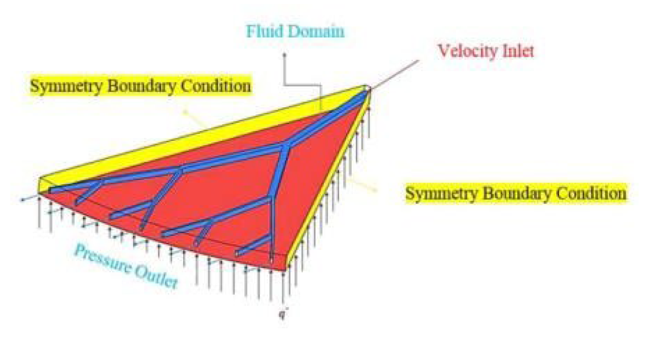
MCHS was introduced by D.B. Tuckerman and R.F.W. Pease at Stanford University in 1981. [11]. Since then, various academics have conducted extensive research on MCHS. [12]. MCHS is a heat sink that has micro extrusions that allow the working fluid to flow through it for heat transfer in electronic devices [Figure 4]. Microchannel heat sinks can generate very high heat transfer rates with increase in heat transmission because of small passage size and large area of surface to volume ratio [4].
To achieve least pressure losses and thermal resistance, a few design variables must be taken into account while designing MCHS. These include material of the MCHS, number of pin-fins, shape, and fin alignment. [5]. Material selection is primarily based on the thermal conductivities of materials [14]. MCHS is made of good thermal conductors like copper and aluminum. Copper costs more in terms of money than Aluminum, but it is roughly twice as conductive compared to Aluminum and hence more efficient [15]. Aluminum can easily be formed by the extraction and has less weight that faces less stress on fragile parts. Because of these properties of aluminum, complex cross-sections can be made. Also, Zinc is an acceptable material for heat sinks. As in the casting process when zinc is mixed with an alloy, it degrades its porosity, unlike copper and aluminum. But the thermal conductivity of zinc is less than both copper and aluminum [15]. The inclusion of fins has a major effect on the effectiveness of MCHS. Most heat exchangers require a large heat transfer per volume ratio for electronics cooling as the number of fins increases, this ratio will correspondingly rise. [16]. However, increasing the quantity of fins also increases the amount of pressure loss, which require extra pumping power. [17]. Different shapes of fins i.e., Pin fins, wavy fins, straight fins, fluted fins, etc. are used in MCHS [18]. Other non-standard fins are also present and new geometries are also being designed. These non-standard fin shapes are unique or specialized arrangements made to meet certain thermal management requirements or to solve particular heat dissipation challenges. The most commonly used pin fins include square, hexagonal, cylindrical, and elliptical [18]. Straight fins with rectangular cross-sections are also very common.
A forced convection system is one that uses a pump to aid with fluid flow [19]. In that case, the cross-sectional area for flow, volumetric flow rate, and pressure drop are all system limitations. Otherwise, these are the design specifications. Resistance to the coolant movement is called pressure drop. It does not create much difference, but still, the selected MCHS shape changes overall pressure losses of system [20]. So, the MCHS selected should have less pressure losses than pump delivery pressure. The turbulence of flow is determined by the flow rate of the incoming liquid. When fan is specified, it’s flow regime and fluid velocity are known. [21]. Thus, increasing the velocity at the entrance raises the volumetric flow rate, which in turn promotes turbulence. If the flow is laminar with the given geometry, the thermal resistance will be enhanced. Specifically, for an entrance velocity of 2.5 m/s and a channel length of 50 mm, the thermal resistance decreases from 0.035 K/W to 0.022 K/W, demonstrating the significant impact of flow velocity on thermal performance. The cross-sectional area for flow can be designed based on the rate of flow requirements. If the cross-sectional measurement of channel becomes smaller, more input is required to pump fluid at required rate [20].
2. Methods Used to Enhance the Thermal Efficiency of MCHS
As the heat flux removal requirements from MCHS rise, several strategies are developed to improve MCHS’s capability of dissipating more heat effectively. These methods can be divided into two categories: active methods and passive methods. [22]. Figure 6 illustrates the details of these strategies
2.1. Active Techniques
Active methods increase the thermal efficiency of smooth rectangular MCHSs by utilizing outside energy sources [8]. Go JS et al. [23] Investigated effects of vibration induced by flow on thermal performance in 2003 in micro fin array. They reported that a larger heat exchange rate was achieved through raising the micro fin’s vibration displacement because vibration-induced chaotic convection. They compared the thermal performance based on thermal resistance encountered in plain wall and micro fin array heat sink. The evaluated heat transfer rate was found to be an increase of 5.5 and 11.5% at air velocities of 4.4 and 5.5 m/s, respectively. Hessami et al. [24] Investigated the impact of flow pulsation technique on smooth MCHS performance. Their research revealed that raising the frequency and decreasing the intensity of flow pulsation led to improved heat removal.
Active techniques are those techniques which uses external power source or energy for thermal performance enhancement in microchannel heat sink. The major reason to use both or either active techniques or passive technique is to disrupt the flow and secondary flow generation. Due to its compact size Active techniques have not been used more often in microchannel comparing to passive techniques. Different approaches have been used by researchers like electrostatic forces, flow pulsation and vibration etc. Krishnaveni et al. [25] Proposed rectangular MCHS by inducing chaotic mixing in flow through the application of an electrostatic field. Morini et al. [26] numerically studied the electro osmotic flow (EOF) in MCHS having rectangular and trapezoidal cross sections Using Poisson– Boltzmann equation and the Navier–Stokes equations. The results demonstrated the Reynolds numbers are in general low for EOF and for this reason, in the analysis of the heat transfer, the contribution related to the axial conduction along the silicon wafer can be important because it changes the axial distribution of the heat flux. Han et al. [27] has evaluated the thermal performance of pure electro-osmotic flow (EOF), pure pressure driven flow (PDF), and combination flow (CF) using numerical simulations. They observe notable disruption in fluid motion with the aid of EOF, particularly in smaller hydraulic diameter MCHS.
Narrein et al. [28] numerically investigated a helical shaped microchannel heat sink with working fluid (Al2O3/water). They compare performance for steady and pulsatile flow and it was observed that pulsatile flow has better heat transfer with marginal reduced pressure drop. Nandi and Chattopadhyay [29] implemented pulsatile flow in a microchannel in wavy shape. They concluded their findings that flow pulsation was able to enhance heat transfer with reduced pressure drop even at low range of Re.
2.2. Passive Techniques
Passive techniques are relying on natural mechanisms like convection, conduction, and radiation to remove the heat without the need for mechanical devices like fans or pumps. These techniques facilitate heat transfer using built-in properties of the heat sink and its immediate surroundings. In MCHS, passive cooling techniques are used to dissipate heat in a various applications, including the electronics, automotive, and aerospace sectors. Through a decrease or elimination of the dependence on active cooling components, they provide the benefits of silent operation, less power consumption, and increased system reliability. Some of the passive techniques for heat transfer in MCHS are discussed below.
2.2.1. Flow Disruption Technique
One strategy for improving heat transmission in MCHS is fluid flow obstruction. This technique involves inserting small obstacles into the flow channel to impede the flow and create turbulence. Reducing the thickness of the thermal boundary layer and raising the convective heat transfer rate lead to improved heat dissipation. MCHS can use various flow obstacles, comprising micro fins, micro-pin fins, micro-dimples, micro-cavities, micro-ridges, etc. These microstructures are made to create swirls, and vortices, which encourage heat transmission. The effectiveness in flow obstruction method depends upon several factors, including flow rate, the thermal characteristics of the fluid, obstruction size, shape, and distribution.
2.2.2. Ribs
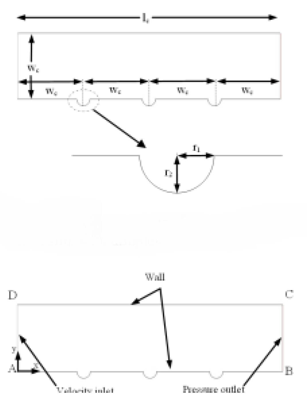
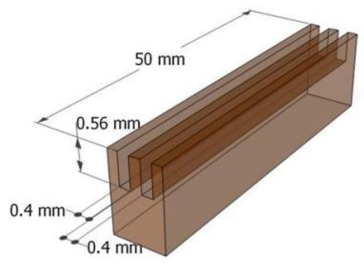
One common method of flow interruption on MCHS walls is the insertion of ribs. On the channel sidewalls, the small projections known as ribs can be positioned in several configurations, including parallel or staggered patterns. The flow turbulences created by these ribs reduce the heat of the thermal boundary layer and raise the heat transfer coefficient. Julian Wang et al. [30] investigated microscale ribs and grooves influence on heat flux rate. They observed that, in comparison to a smooth microchannel, the Nusselt number is increased by 1.1–1.55 times when ribs and grooves are added to the microchannel. Friction factor for the rib-grooved microchannel with compared rib heights of 0.6, 0.73, and 0.85 is more than 0.38 times, 2.16 times, and 4.09 times higher than the smooth microchannel, respectively, according to their investigation into the impact of altering the relative rib height on the friction factor. Xia et al. [31] studied the effect of arc-shaped grooves and ribs on the thermohydraulic properties of a microchannel. Statistical methods were utilized in conjunction with the two target functions and the design elements relative grooves altitude, relative ribs height, and relative ribs width to reduce thermal resistance and pumping power at a fixed volume flow rate. It was found that relative rib height showed the highest performance, with overall thermal resistance decreasing linearly as rib height increased. The impact of various cylindrical ribs and cavities were studied on thermal and flow characteristic of MCHS by Faraz Ahmad et al. [32]. For rib spacing (Sr) = 0.4 mm, the side wall ribs had the maximum thermal enhancement factor of 0.98, while the base wall ribs had the lowest thermal enhancement factor of 0.90. The all-wall rib arrangement achieved a Nusselt number of 12.58, which is 71% higher than the Nusselt number of 7.35 for the smooth MCHS.
Shizhong Zhang et al. [12] studied influence of various arrangements of ribs and cones on walls of MCHS and found that conning at 45 degrees decreases the pressure drop by 85% while reducing the maximum Nusselt number by 25%. Furthermore, it was discovered that hexagonal ribs were the most effective of the various layouts considered. Shahzad Ali et al. [33] analyzed the outcome of adding different arrangements of hydrofoil ribs on the thermo-fluid characteristic of a MCHS. They found best performance was obtained at rib spacing (Sr) = 0.4 mm and the staggered arrangement performed more than the aligned ribs configuration. The maximum performance evaluation factor of 1.06 was found in case of the aligned configuration at Re 1000. Aatif Ali Khan et al. [34] numerically analyzed MCHS with six configurations of ribs. It was concluded that circular ribs have the lowest and rectangular ribs have the greatest pressure drop, while triangular-circular ribs have the highest thermal performance factor. They noted that triangular ribs have least thermal resistance across range of Reynolds number and rectangular ribs have highest thermal resistance. Yao Hsien et al. [35] investigated the influence of ribs and grooves on heat transfer and friction in a rectangular microchannel. They found that the convective heat transfer coefficient was enhanced by 1.40 times, and the friction factor ratio increased by up to 1.30 times. They concluded that the discrete angled arrangement of grooved ribs exhibited the best thermal performance among the configurations studied. Lau. Et al [36] studied the effect of staggered ribs on turbulent heat transfer in a microchannel. It was concluded that discrete ribs with rib angles-of-attack α= 60 degrees and 90 degrees create very high heat transfer from the ribbed walls, while discrete ribs with angles-of-attack α = 45 degrees possess the greatest thermal efficiency. The thermal performance of cooling channels in turbine airfoils is improved by replacing angled complete ribs with these discrete ribs. Shizhong Zhang et al. [37] studied the effect of trefoil ribs walls of MCHS and side wall trefoil ribs provided the greatest performance factor, measuring 1.60. The impact of bidirectional ribs on the heat transfer performance of microchannel heat sinks was studied by Guilian Wang.et al [38]. It was concluded that adding bidirectional ribs increases the Nusselt number by 1.4-2 and 1.2-1.42 times over vertical and spanwise ribs at the expense of increased pressure drop. Sadiq Ali et al. [39] analyzed the thermohydraulic characteristics of MCHS with trefoil-shaped rib. They studied the various trefoil rib shapes and concluded that the side wall trefoil ribs (MC-SWTR) had the highest thermal enhancement factor of 1.6, while the all wall trefoil ribs (MC-AWTR) had the lowest thermal enhancement factor of 0.87 at Re 1000.
M. M. U. Rehman. Et al [36] analyzed influence of unqiue sidewall ribs on the heat transfer and flow characteristics of MCHS. Their research showed that hydrofoil ribs had the highest heat transfer improvement of 26% from various geometrical rib profiles and as a result, the pressure drop of the hydrofoil ribs was also enhanced by 66% as compared to the smooth MCHS. The effect of sinusoidal cavities and rectangular ribs on heat transfer augmentation of the microchannel heat sink was investigated by Ihsan Ali Ghani. Et al [41]. It was concluded that the maximum overall performance enhancement factor of 1.85 with Re = 800 was obtained with a cavity amplitude of 0.15, rib width of 0.3, and rib length of 0.5. Lei Chai et al. [42] investigated the influence of rectangular ribs on the heat transmission properties of an interrupted microchannel and determined the best rectangular rib parameters. It was discovered that the new interrupted microchannel with a length of 0.5 mm has a maximum enhancement factor of 1.35, while MCHS with length of 0.1 mm has the lowest enhancement factor of 1.12. Y.F. Li et al. [43] investigated the effects of triangular and rectangular the cavities and ribs on laminar flow parameters in microchannel heat sinks. They found that a microchannel having triangular cavities and rectangular ribs with a rib width of 0.3 and cavity width of 2.24 gains a thermal enhancement factor of 1.619 at Re=500. Y.L. Zhai et al. [21] evaluated the performance of three types of microchannels and noted that the microchannel with circular ribs has the maximum thermal enhancement factor of 1.5 at Re=600, while the microchannel with rectangular ribs has the lowest thermal enhancement factor of 1. Ayodeji S. Binuyo [44] investigated the effect of an interrupted microchannel on an Al2O3-water-based nanofluid. The study concluded that increasing the pulse amplitude increased the Nusselt number, and increasing the pulsating frequency improved the heat transfer enhancement compared to decreasing the pulse amplitude.
Abdelkader Korichi et al. [45] investigated the impact of heated obstructions placed on the top and bottom walls of a microchannel. Their analysis revealed that the presence of these obstacles enhanced heat transfer by up to 123.1% when increasing the Reynolds number from 50 to 500, and by 48.5% when increasing from 500 to 1000, as indicated by the overall Nusselt number. Aparesh Datta et al. [46] studied the influence of triangular cavities and ribs on microchannel heat transfer performance. It was reported that back-to-back cavities with widths 0.75 times and lengths 0.0454 times the basic microchannel provided the best thermal performance. They also observed that coppers MCHS has the highest thermal performance of 2.31 and silicon’s MCHS has a thermal performance 1.96. Faraz Ahmad et al. [47] examined a microchannel heat sink’s conjugate heat transfer capabilities with side wall ribs. It was concluded that elliptical ribs had the maximum Nusselt number because of greater streamlining effect and that more than 96% of losses are due to heat transfer in the microchannel heat sink.
Q.Zhu et al. [48] analyzed the effect of rectangular grooves and rectangular ribs on thermohydraulic characteristics of MCHS. Different configurations of grooves and ribs were investigated and found that grooved channel having rectangular ribs gives optimum efficiency with a rib width of 0.25. In order to maximize the Nusselt number while maintaining the lowest possible friction factor, several rib designs were used. The Nusselt number and pressure drop were found to be significantly impacted by the spacing between ribs, the angle at which ribs are installed, and the geometry of ribs (e.g., circular, cone shape, miro-scale, trefoil ribs, and hexagonal ribs) [12,30,32,34,36]. Nusselt number increases when rib spacing decreases, but pressure drop also rises as a consequence. Placing ribs at angles minimizes fluid flow resistance which is required to overcome the problem of pressure drop.
The following tables serve to provide a concise overview of the nature of the research work and the key parameters related to the MCHS. Table 1 describes the additional data for ribs as flow obstruction technique.
Figure 7.
Rectangular microchannel with Micro-scale Ribs and Grooves by Guilian Wang.et al [30]. Reproduced with permission from Guilian Wang. et al. [30]; published by Electronic materials, 2024.
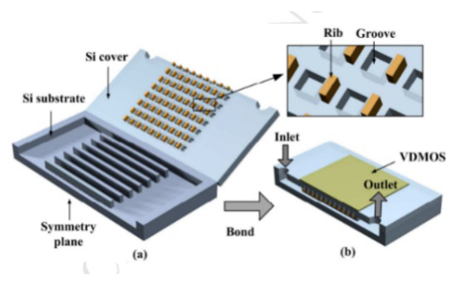
Figure 8.
Rectangular microchannel with arc-shaped ribs and grooves G. D. Xia et al [31]. Reproduced with permission from G. D. Xia et al [31]; published by Electronic materials, 2024.
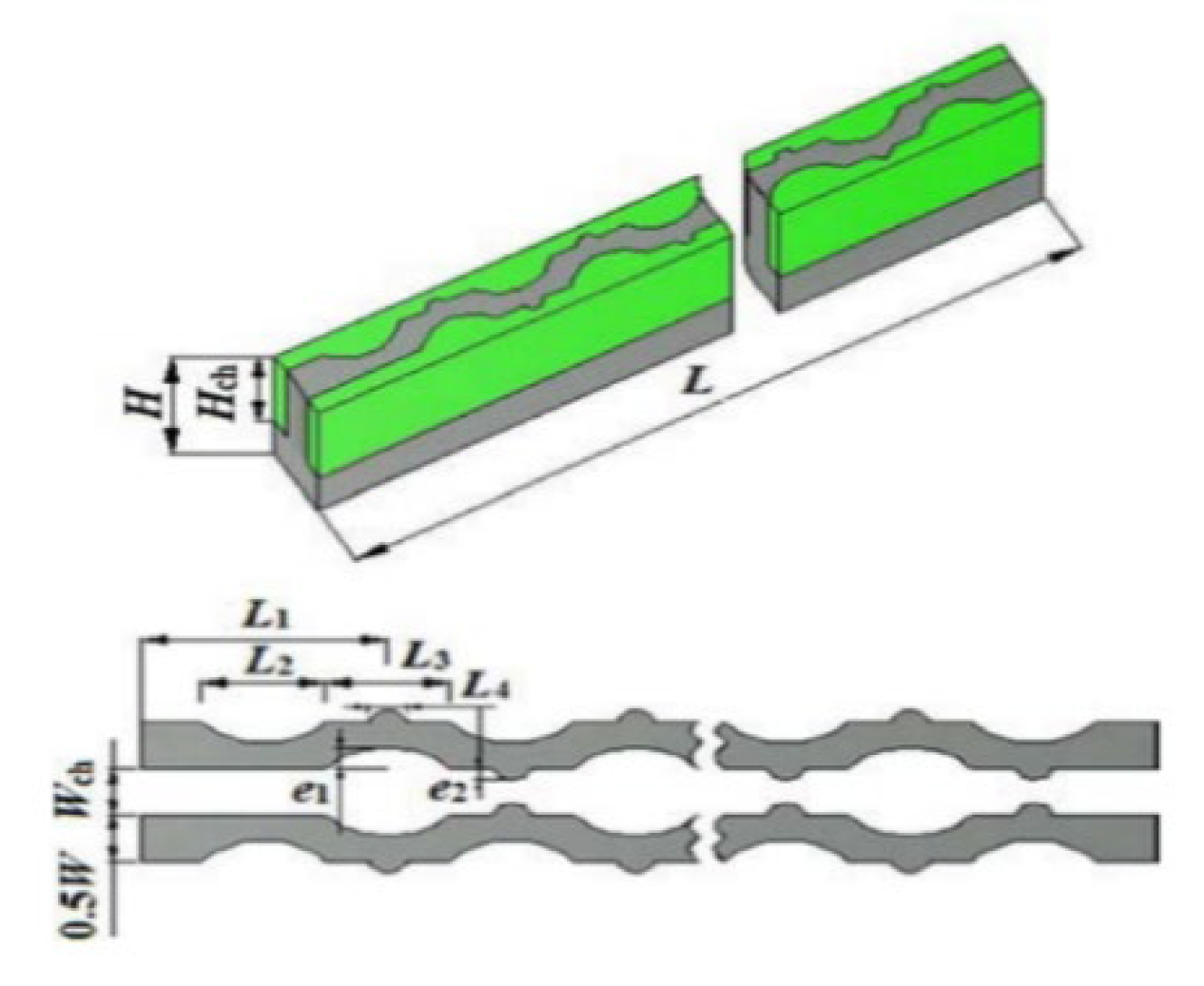
Figure 9.
Rectangular microchannel with cylindrical ribs and cavities byFaraz Ahmad. et al. [32]. Reproduced with permission from Faraz Ahmad. et al. [32]; published by Electronic materials, 2024.
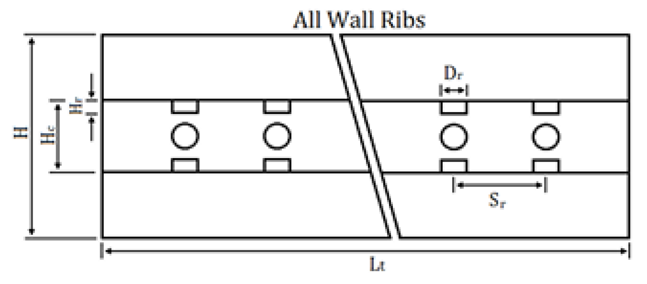
Figure 10.
Rectangular microchannel with trefoil-shaped ribs by Shizhong Zhang. et al. [12]. Reproduced with permission from Shizhong Zhang. et al. [12]; published by Electronic materials, 2024.
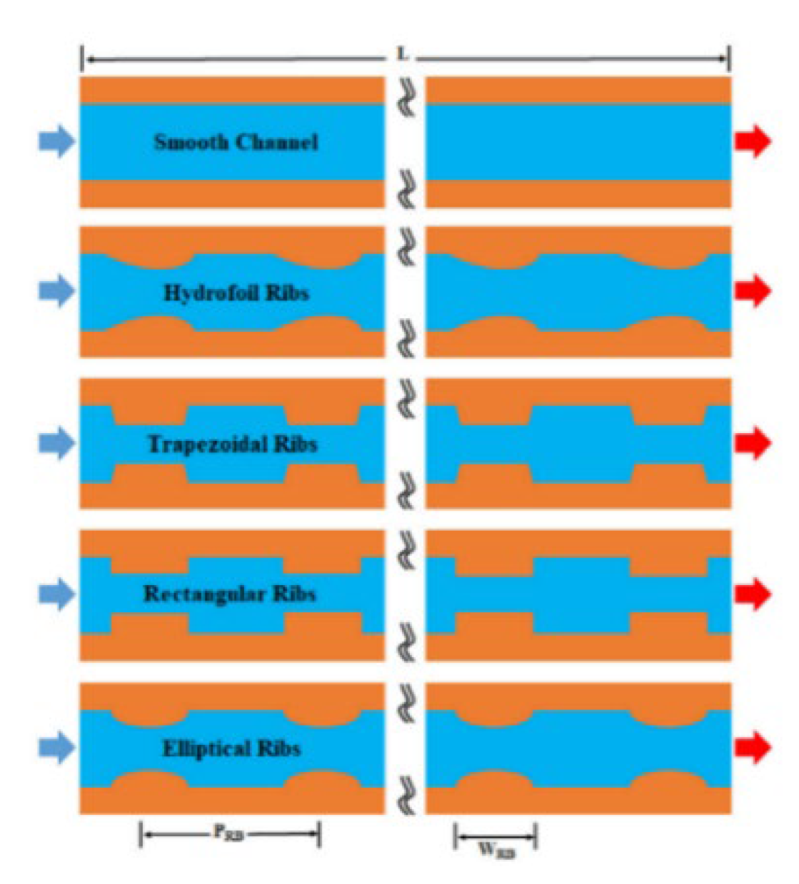
Figure 11.
Rectangular microchannel with Hydrofoil Ribs by Shahzad Ali. et al. [33]. Reproduced with permission from Shahzad Ali. et al. [33]; published by Electronic materials, 2024.
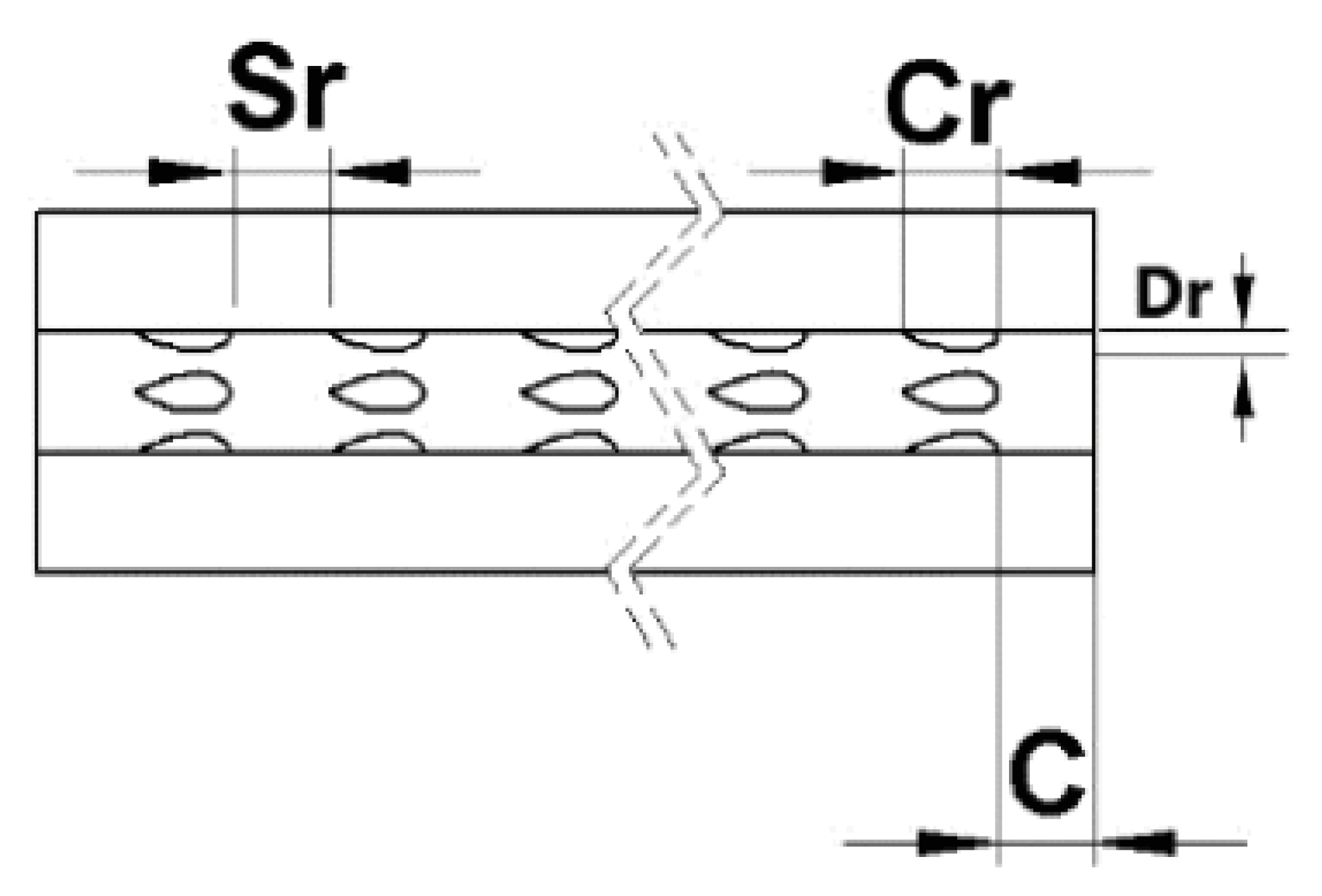
Figure 12.
Rectangular microchannel with ribs and cones by Shizhong Zhang. et al. [37]. Reproduced with permission from Shizhong Zhang. et al., [37]; published by Electronic materials, 2024..
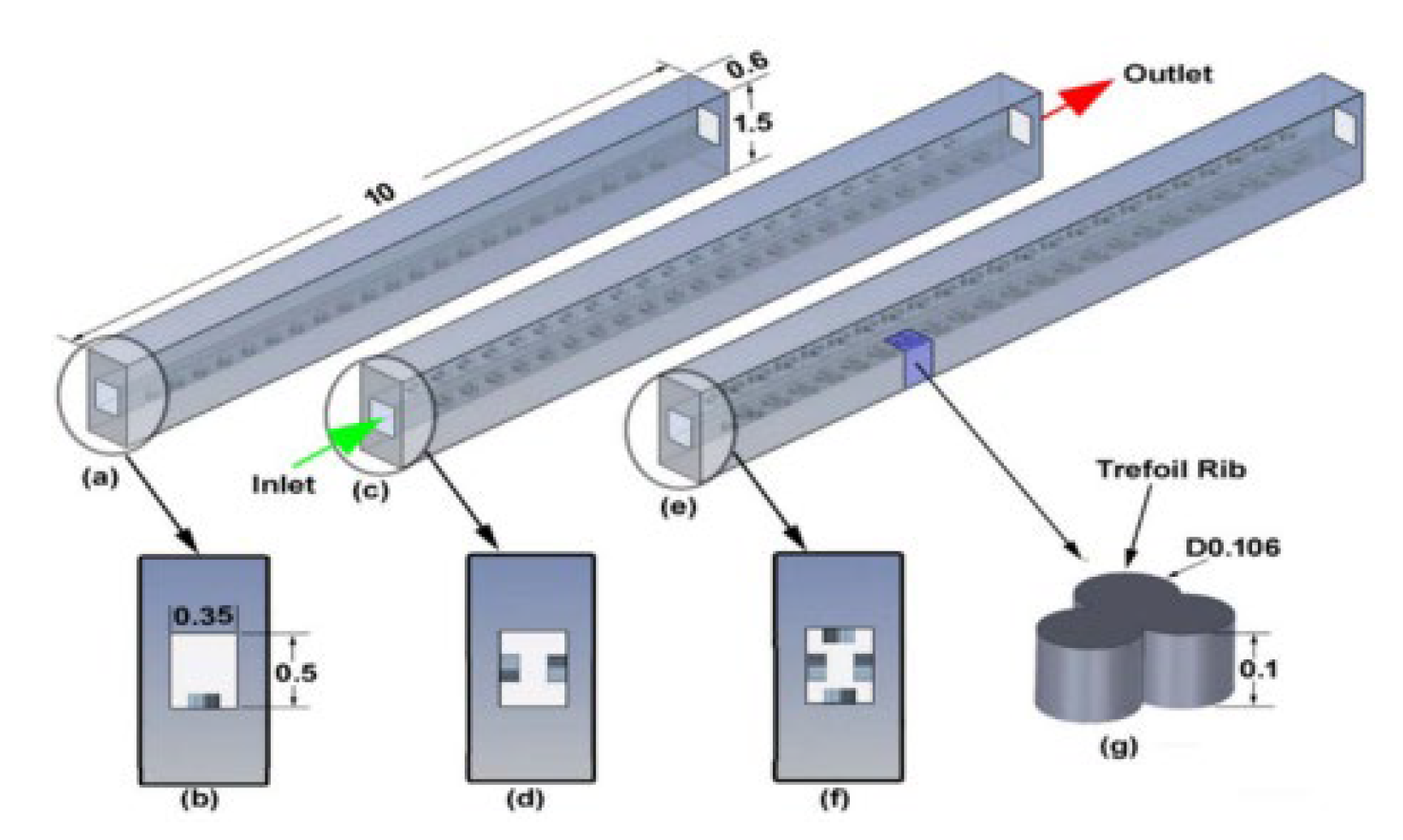
Figure 13.
Rectangular microchannel with bidirectional Ribs by Guilian Wang.et al [38]. Reproduced with permission from Guilian Wang.et al [38]; published by Electronic materials, 2024.
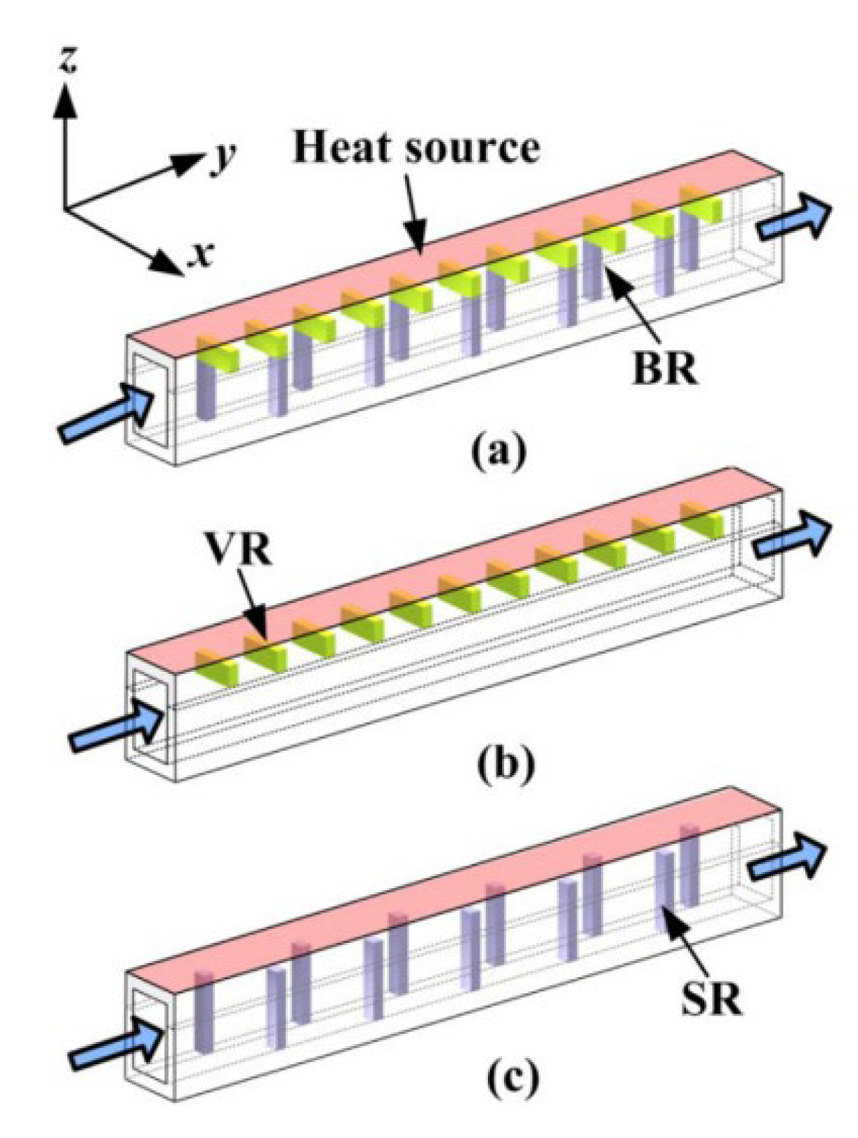
Figure 14.
Rectangular microchannel with trefoil-shaped ribs by Sadiq Ali. et al. [39]. Reproduced with permission from Sadiq Ali. et al., [39]; published by Electronic materials, 2024.
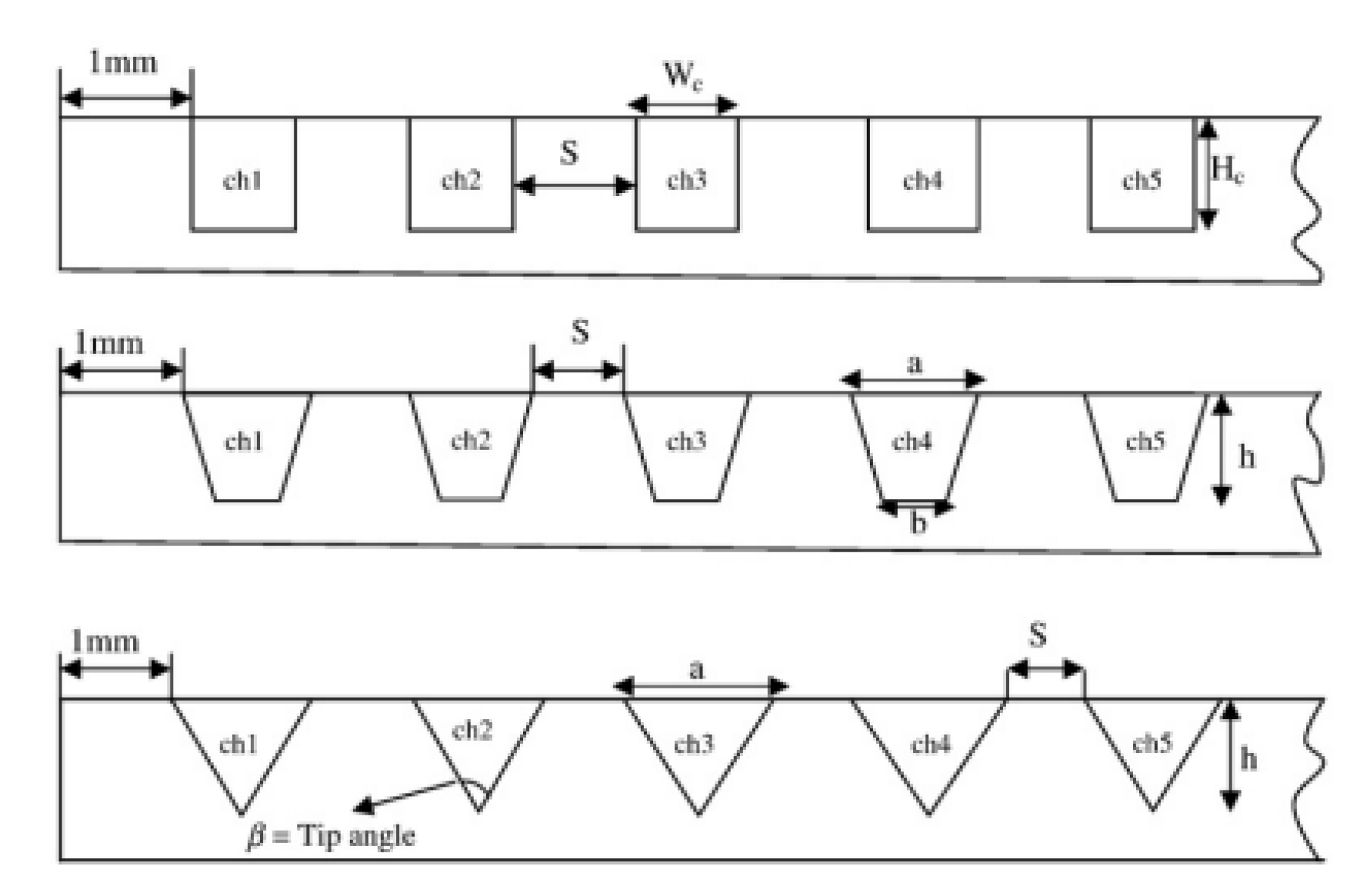
Figure 15.
Rectangular microchannel with rectangular ribs and sinusoidal cavities by Ihsan Ali Ghani. et al. [41]. Reproduced with permission from Ihsan Ali Ghani. et al. [41]; published by Electronic materials, 2024.
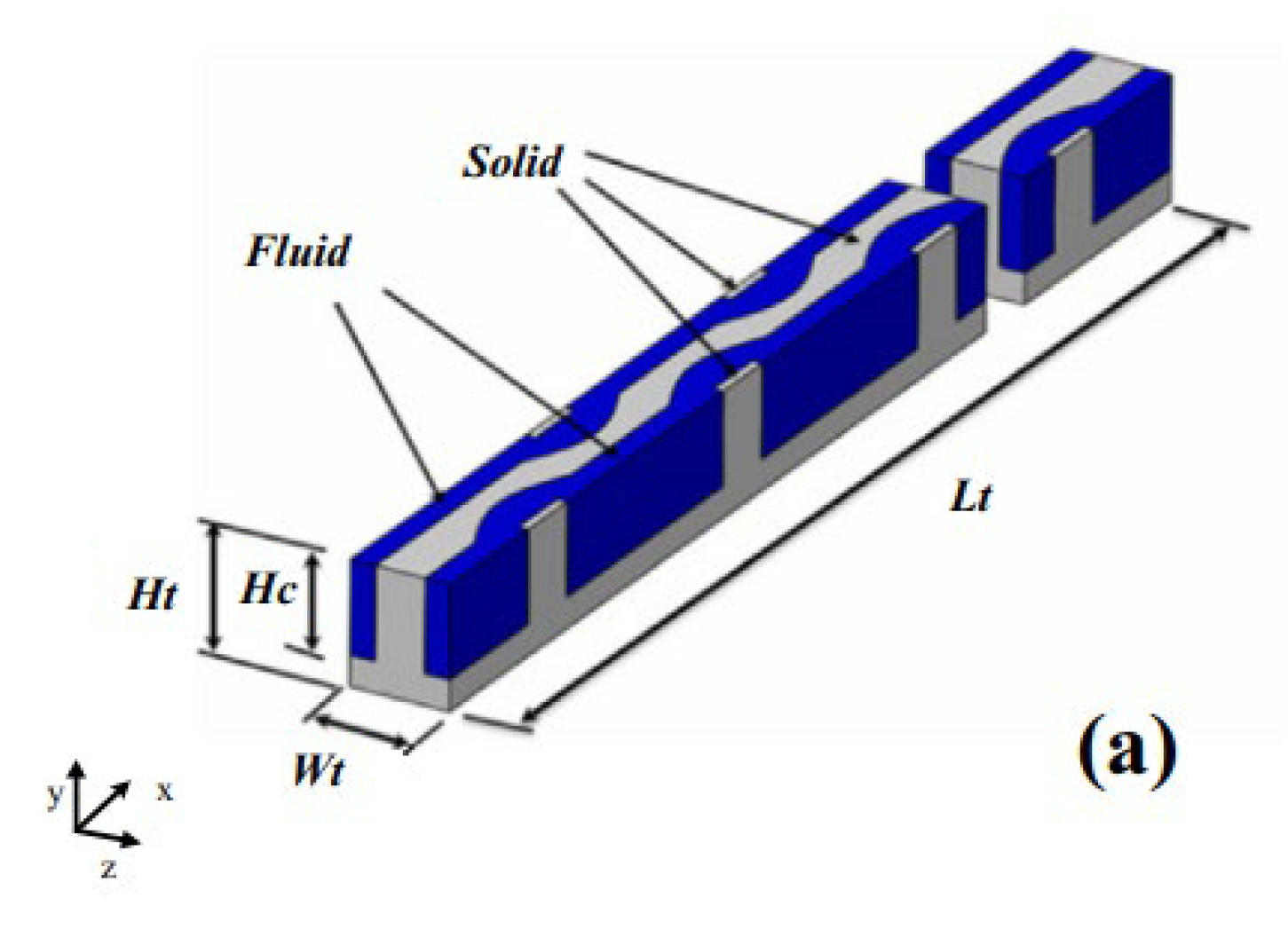
Figure 16.
Interrupted microchannel with rectangular ribs by Lei Chai. et al. [42] Reproduced with permission from Lei Chai. et al. [42]; published by Electronic materials, 2024.
Figure 17.
Rectangular microchannel with rectangular ribs and triangular cavities Y.F. Li. et al. [43]. Reproduced with permission from Y.F. Li. et al. [43]; published by Electronic materials, 2024.
Figure 18.
Rectangular microchannel with rectangular, trapezoidal, and circular Ribs by Y.L. Zhai. et al. [21]. Reproduced with permission from Y.L. Zhai. et al. [21]; published by Electronic materials, 2024.
Figure 19.
Interrupted microchannel on an Al2O3-water-based nanofluid by Ayodeji S. Binuyo [44].
Figure 19.
Interrupted microchannel on an Al2O3-water-based nanofluid by Ayodeji S. Binuyo [44].
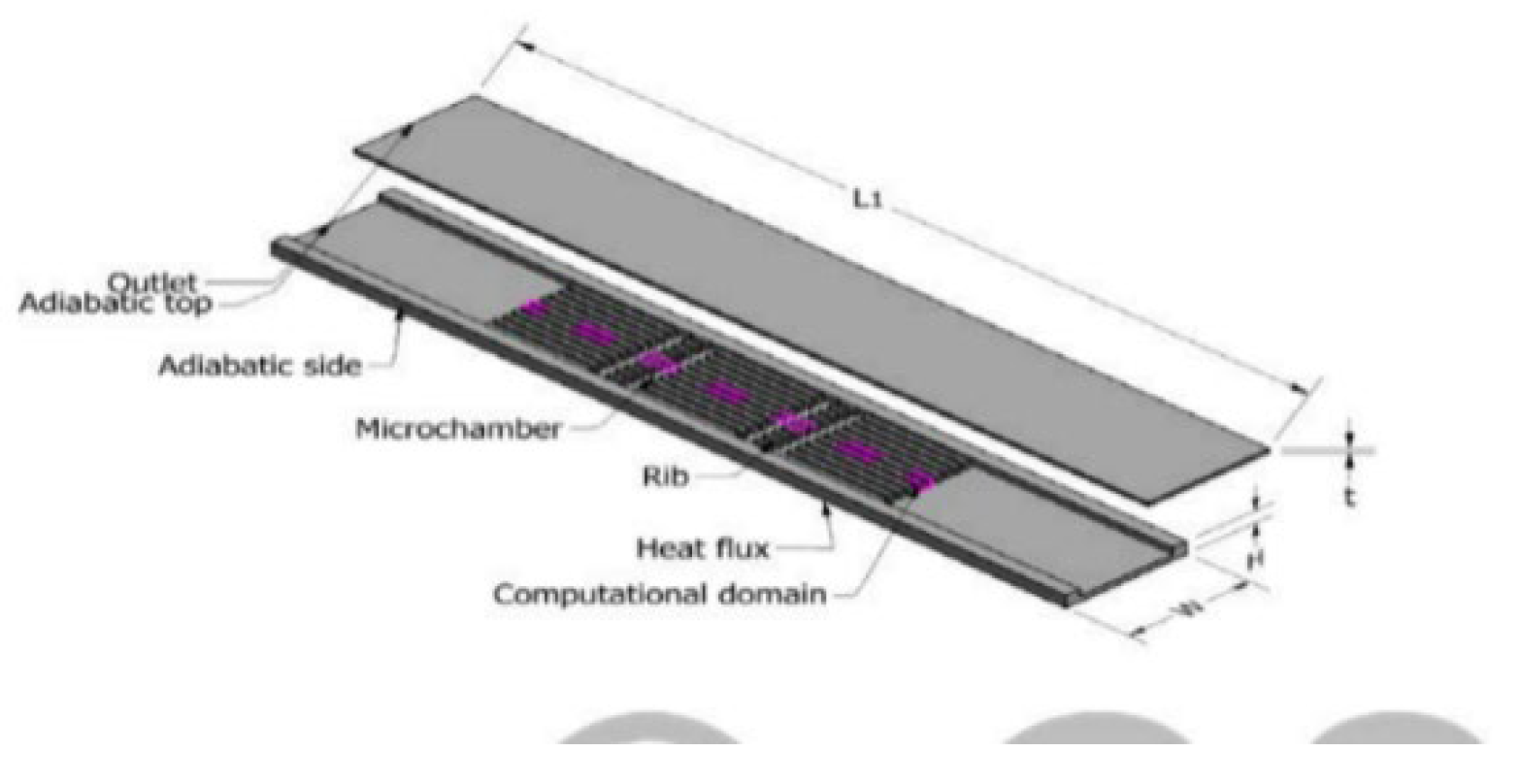
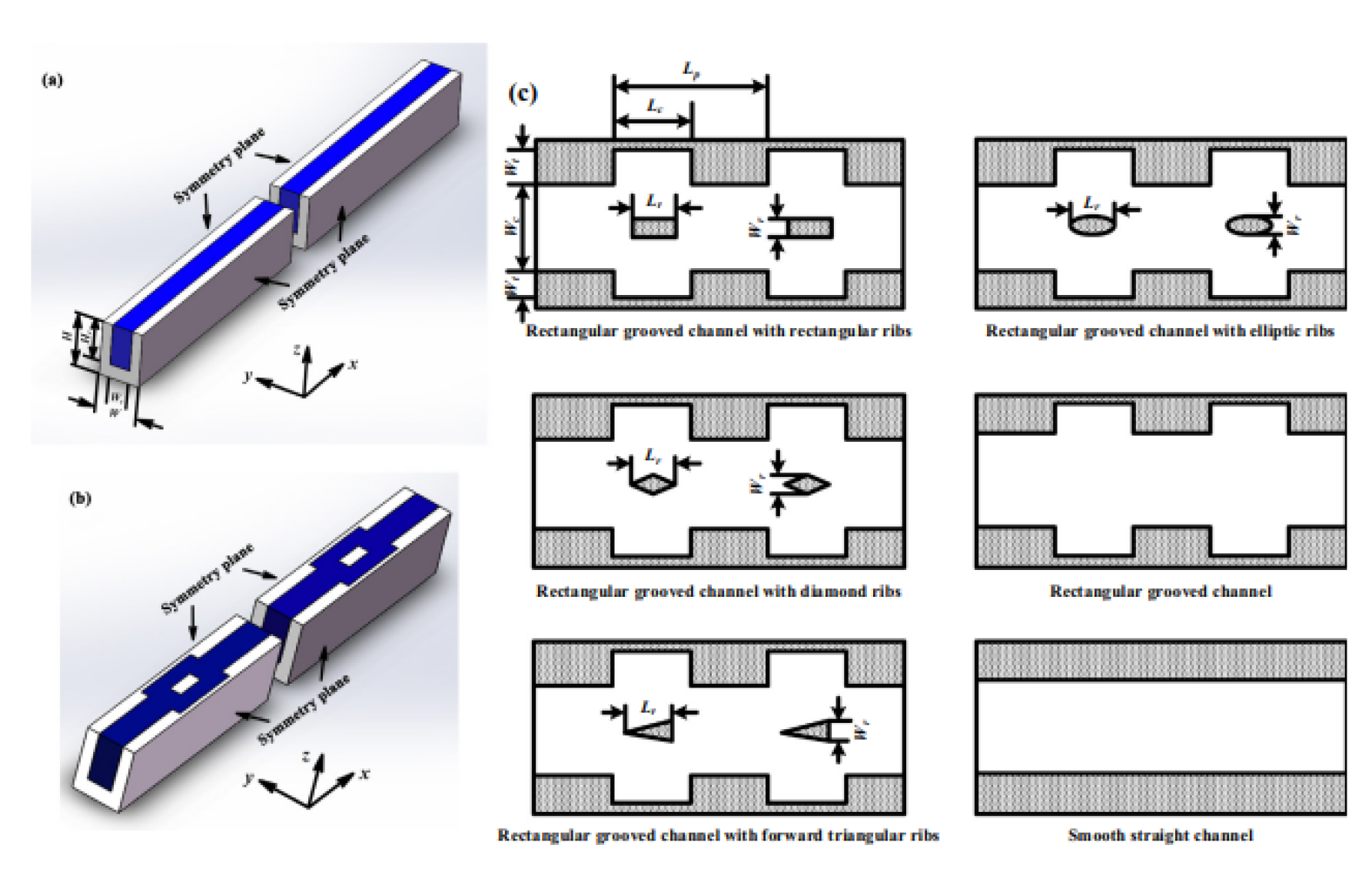
Figure 20.
Rectangular with rectangular grooves and different-shaped ribs by Q.Zhu et al. [48].
Figure 20.
Rectangular with rectangular grooves and different-shaped ribs by Q.Zhu et al. [48].
2.2.3. Grooves
Another technique for improving the thermal performance of MCHS is the introduction of grooves in MCHS. Grooves can effectively increase the thermal characteristics of MCHS. Grooves help to rise the surface area of the MCHS, which allows for a greater amount of heat dissipation. The increased surface area allows for more contact with the cooling medium, fluid flow also increases due to the grooves in MCHS which can help to remove heat more efficiently. The grooves can create turbulence in the fluid flow, which can promote better mixing and heat transfer. Overall, the inclusion of grooves in MCHS can lead to improved thermal performance, making them more effective at dissipating heat and cooling electronic devices. Hamdi E. Ahmed et al. [49] investigated the impact of design factors on grooved microchannel heat sinks (MCHS). Their analysis showed a 2.35% increase in the friction factor, from 0.183 to 0.187, and a 51.59% improvement in the Nusselt number, from 22.4 to 33.9. These changes led to the most effective thermal design for MCHS. Pankaj Kumar [50] studied heat transfer in trapezoidal microchannels with Reynolds numbers from 96 to 720. The study found a 12% increase in heat transfer efficiency for trapezoidal channels compared to rectangular ones, and a 28% enhancement with grooves in the trapezoidal channels. The simulations were conducted with a constant heat flux of 100 W/cm². The geometry with Semi-circular grooves had an extra pressure drop from frictional loss and 16% higher heat transfer than rectangular grooves. Guodong Xia. et al. [51] numerically investigated MCHS with triangular reentrant cavities to find the impact of geometric factors on heat transfer. Four design variables are taken for optimum thermal design. For Re= 406.94, and Re = 611.25, 814.09, and 1015.96 the optimal parameters are discussed. et al. [52]studied the grooved channel with curved vanes using holographic interferometry. Heat transfer is raised by factor of 1.5 to 3.5 around Re= 450 and the pressure drop increased by 3 to 5 times as compared to smooth MCHS. A range of groove structures, such as curved vanes [52], semi-circular grooves, rectangular and trapezoidal grooves [46], and triangular reentrant cavities [51] are covered in this section. Semi-circular grooves improves heat transmission at the expense of higher pressure drop. Furthermore, variations in Reynolds number also influence the performance of the grooves [51]. Table 2 gives detailed information about the research work done on grooves.
Figure 21.
Grooved MCHS by Hamdi E. Ahmed.et al [49]. Reproduced with permission from Hamdi E. Ahmed.et al [49]]; published by Electronic materials, 2024.
2.2.4. Cavities and Dimples
Utilizing cavities and dimples on the surface of MCHS is another method for improving heat transfer. Vortices and swirls in the flow are produced by cavities and dimples, which cause mixing and improve heat dissipation. Minghai Xu et al. [54]. investigated the thermal performance of microchannel heat sinks with aspect ratios of 1:1 to 4:1 and dimple configurations (0.2 mm radius, 0.1 mm depth) at a Reynolds number of 500. Results show a significant increase in the average Nusselt number from 8.21 to 9.44 (15%) with dimples, and a 2% reduction in pressure drop, demonstrating enhanced heat transfer efficiency and reduced fluid resistance.Yu Chen. et al. [55] conducted numerical investigations over the dimpled surface with turbulent channel flow. Reynolds number ranges from 4000 to 6000 However, the Prandtl number remains unchanged at 0.7. The results showed an asymmetric dimple with a 15% stream-wise skewness and a depth ratio of ℎ/D = 15%. When compared to a symmetrical dimple with the same depth ratio, heat transmission increased considerably while pressure loss remained unchanged.
The microchannel with turbulent flow over a dimpled surface was experimentally studied by Moon. et al. [56]. The thermochromic liquid crystal (TLC) technique was used to evaluate the local heat transfer coefficient. The channel heights of 0.37, 0.74, 1.11, and 1.49 were examined in range of Reynolds number from 12000 to 60000. The Nusselt number of dimpled walls is 2.1 times that of a conventional channel, yet the friction factor is only 1.6 to 2.0 times that of a conventional channel in thermally developed area. S. Gururatana [57] investigated the micro-channel heat sink (MCHS) with dimples and found that the dimples have a significant impact when the Reynolds number exceeds 125. Specifically, when the Reynolds number increases from 100 to 300, the pressure drop rises from 0.1 to 0.4, while the heat transfer increases from 0.2 to 0.26. Heat transfer is enhanced by the turbulence generated by dimples and cavities. In this section, different studies are summarized which include the effect of dimples at different Reynolds numbers, dimples with varying aspect ratios [54], turbulent flow channels [55], thermochromic liquid crystal (TLC) technology to analyze dimples and cavities [56], and varying channel heights. Heat transmission rises in response to an increase in Reynolds number [57].Table 3 gives the additional information for cavities and dimples as flow disruption technique.
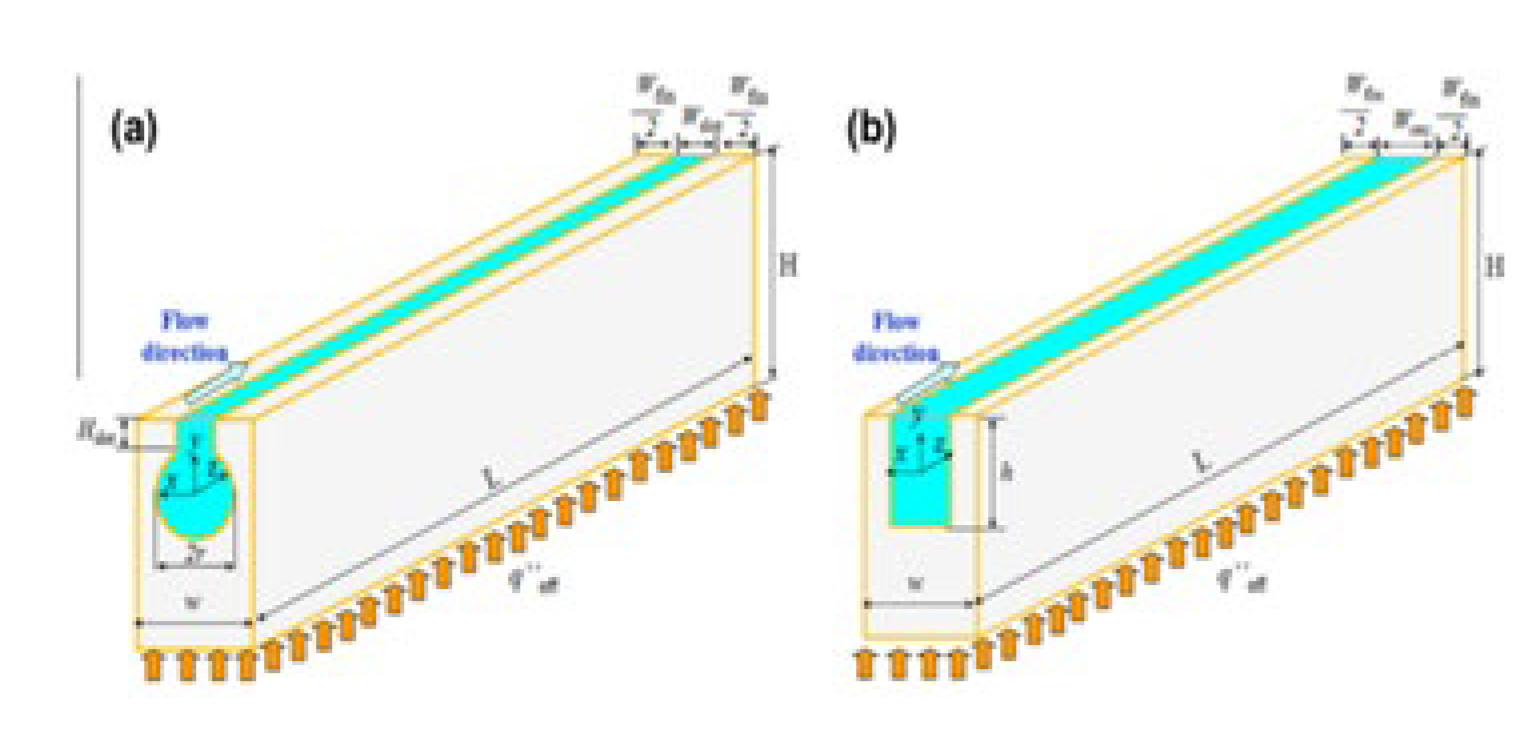
Figure 23.
MCHS with hemispherical shape protrusions/ dimples by Mohib-ur-Rehman [53]. Reproduced with permission from Mohib-ur-Rehman [53]; published by Electronic materials, 2024.
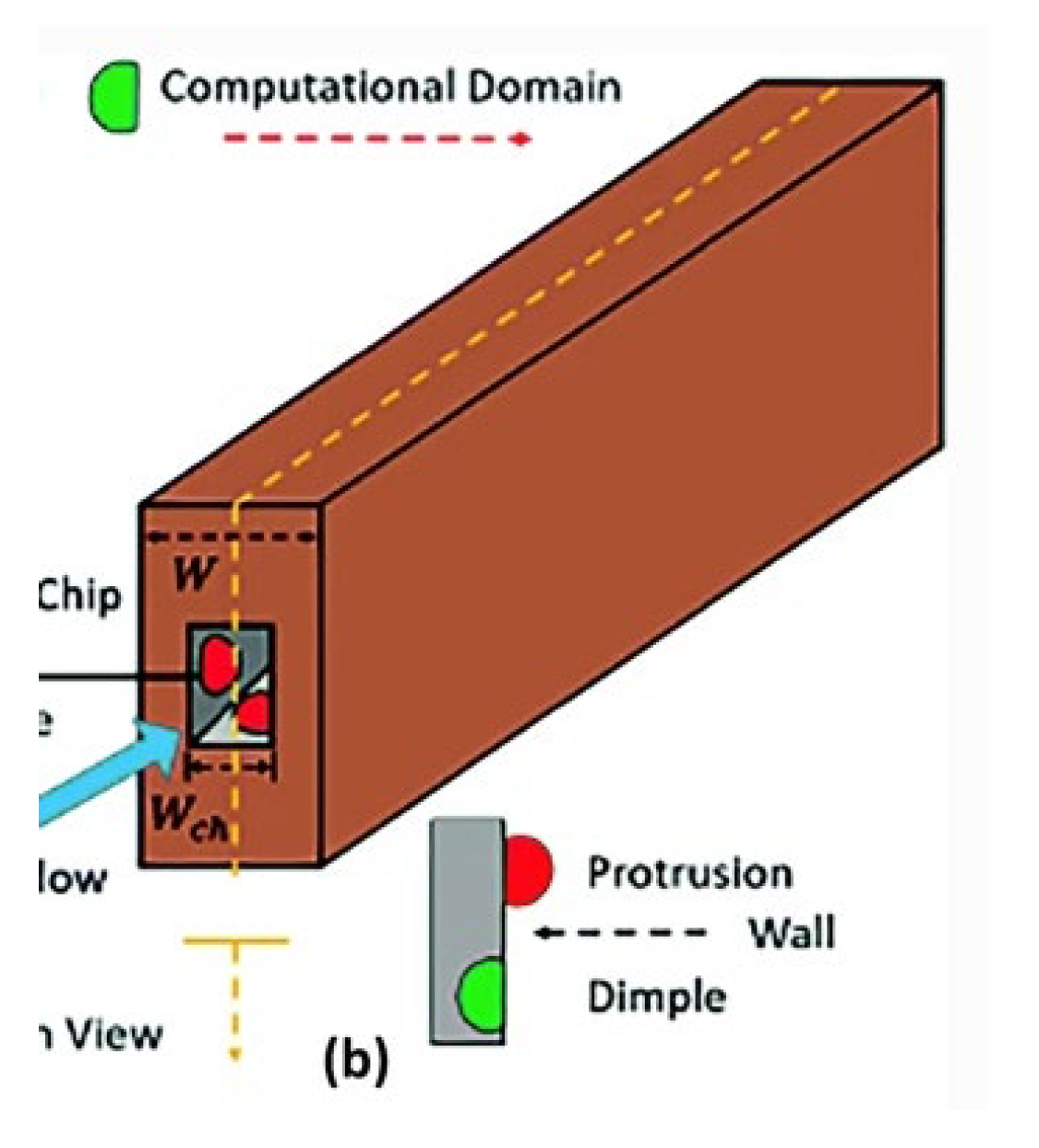
Figure 24.
MCHS with turbulent flow over the dimpled surface by Yu Chen [55]. Reproduced with permission from Yu Chen [55]; published by Electronic materials, 2024.
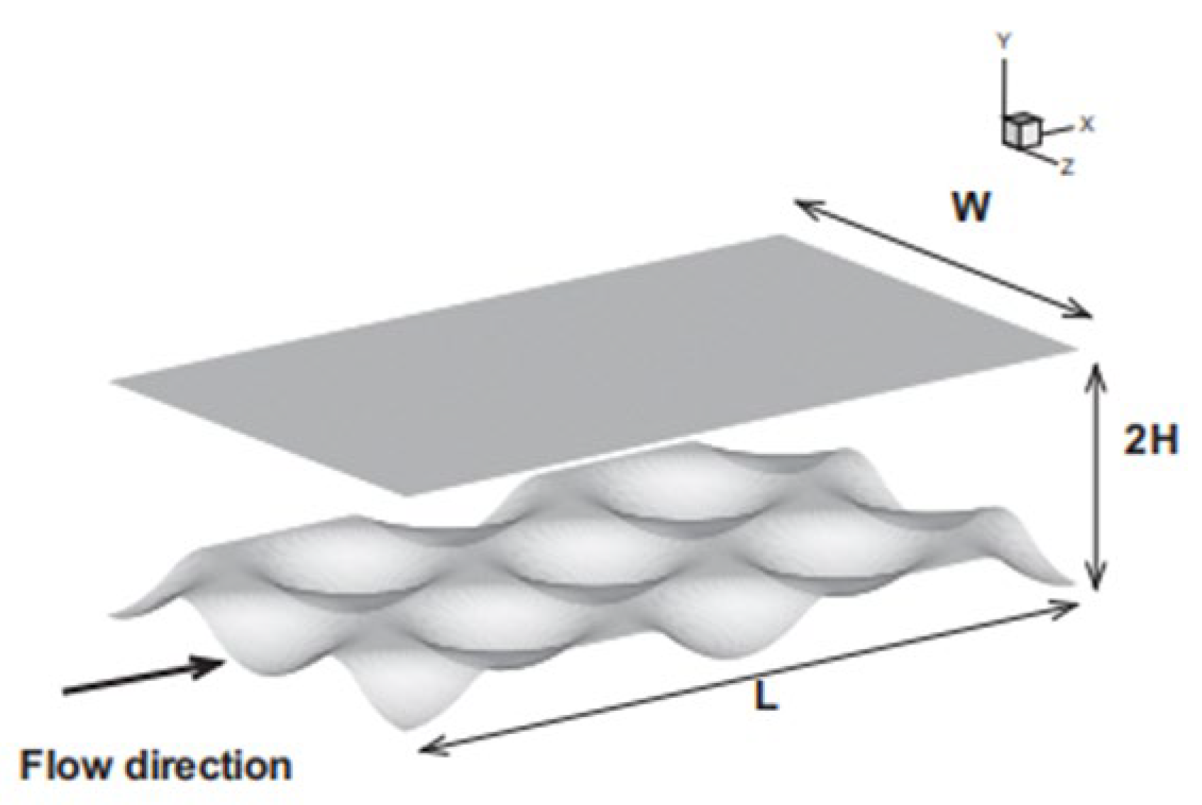
Figure 25.
MCHS with dimples by Minghai Xu [54]. Reproduced with permission from Minghai Xu [54]; published by Electronic materials, 2024.
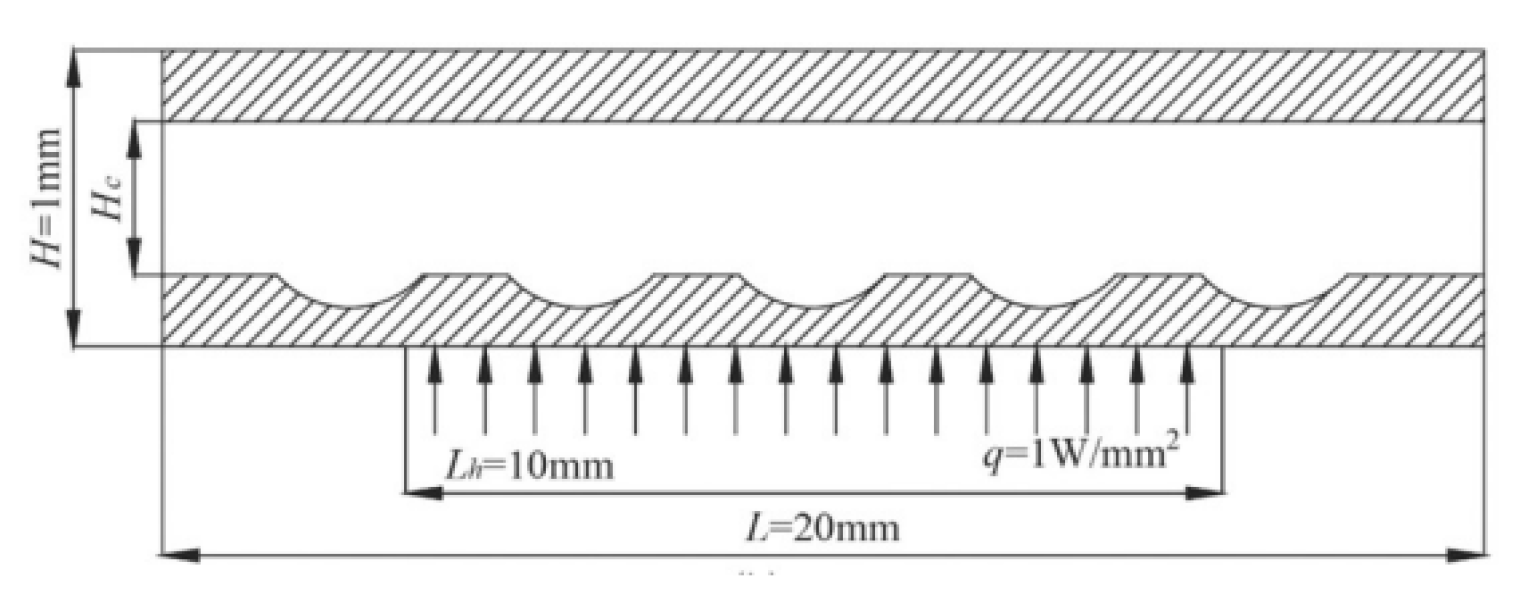
Figure 26.
Rectangular MCHS with concavities by Moon [56].
Figure 26.
Rectangular MCHS with concavities by Moon [56].
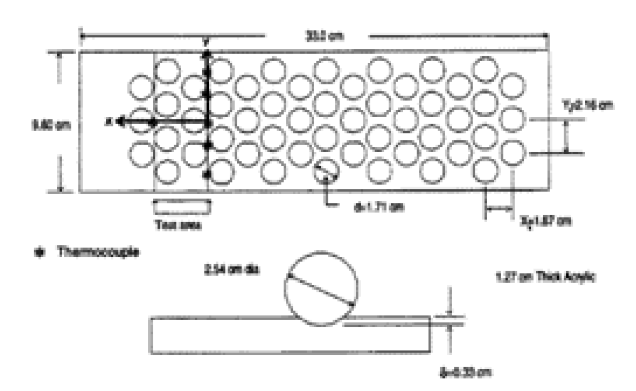
Figure 27.
Computational domain of Suabsakul Gururatana [57].
Figure 27.
Computational domain of Suabsakul Gururatana [57].
2.2.5. Micro-Fins
Another method of disrupting the flow in microchannel heat sinks is micro fins. Small protrusions called pin fins are positioned in the flow route. The pin fin’s turbulence in the flow enhances heat transmission by expanding the surface area available for heat transfer and promoting mixing. Nawaz Khan. et al. [17] numerically analyzed the different configurations of fins with varying heights mounted at the channel’s base wall. The study found that when the Reynolds number was between 150 and 350, the maximum Nusselt number was obtained by using full-length fins upstream, and when the Reynolds number was higher, the maximum Nusselt number was obtained by using full-length fins at the microchannel’s inlet and exit. The lowest pressure drop had achieved using a full-length fin at the center of the microchannel. Dogan. et al. [16] experimentally studied the heat transfer using horizontal microchannel having longitudinal fins with varying heights and spacing, for an extensive range of altered Rayleigh numbers. Their findings indicate that maximal heat transmission occurred at the spacing of S= 8-9 mm, and that the ideal spacing relies on the Rayleigh number. Offset strip-fin microchannel was studied numerically for convective heat transfer by F.Hong et al. [54]. The geometric characteristics of the strip-fins, such as fin thickness (Ww), channel width (Wc), fin depth (Hc), fin interval (L1), and fin length (Ls), were used to study the efficiency of offset strip-fin MCHS. Two dimensionless numbers are used to find the effect of fins on pressure drop, which are K= L1/Ls and M= L/ (Ls + L1. Results concluded that K=1 was optimal for better heat transfer of offset strip-fin MCHS . Ping Li.et al [59] numerically studied and optimized the dimpled and pin-finned water-cooled microchannel. Reynold’s number ranges from 50-300 and the findings demonstrated that for all Reynolds values, the Nu increased with increasing pin diameter and decreasing separation. Thermal performance was a maximum of 10.35 at Re=200. Wazir. et al. [60] studied effect of full length round pin fins on thermal and flow characteristics of MCHS. They found that MCHS with MC-Mixed configuration achieved highest thermal enhancement factor of 1.4 and Nusselt number increase of 2.3 times compared to smooth MCHS. Microfins with different shapes, heights, and spacing [17] have been analyzed. It has been found that having full-length fins in the middle of the channel lowers pressure drop, and a full-length pin fin at the start and at the end improves the heat transfer. Additionally, the Rayleigh number determines the appropriate fin spacing in the microchannel heat sink [16].
Details are given in Table 4 on the application of micro-fins in microchannel heat sinks.
2.2.6. Channel Curvatures
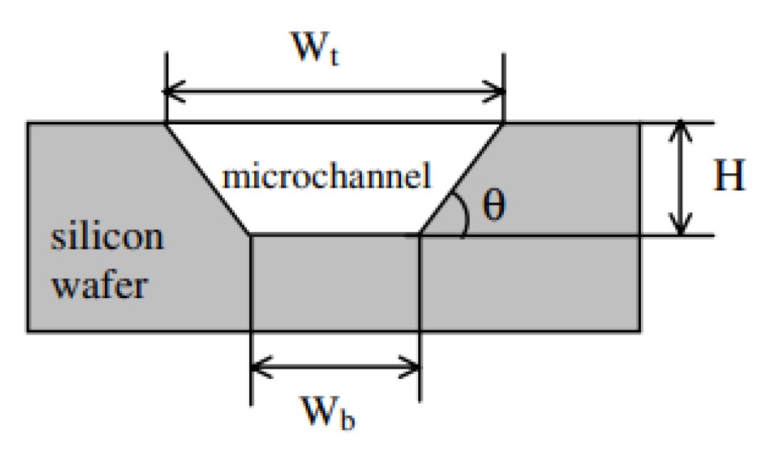
Changing the channel curvatures is another method for enhancing the MCHS’s thermal performance. The curvature of the channels affects the thermal performance of microchannel heat sinks. Centrifugal forces are experienced by the fluid flowing through a curved channel, which may enhance the fluid velocity along the channel’s outside walls. This higher velocity encourages more efficient heat transfer between the fluid and the channel walls, enhancing the heat sink’s total heat transfer capabilities. The channel walls’ surface area may also be increased by the curvature, increasing the area where heat can be transferred. Chu. et al. [61] examined the four sets of triangular microchannels experimentally and noted how heat transmission and pressure drop were affected. Reynold’s number increases cause the friction factor to drop nonlinearly. The Nusselt number increases as the Reynold number increases in the low Reynold number zone, which is less than 100. Following Re=30, the Nusselt number increases slowly. The Correlation between numerical and experimental results is within 15%. Deng et al. [62] found that in a reentrant microchannel heat sink, the Nusselt number increased by up to 39% from 10 to 13.9, and thermal resistance decreased by up to 22% from 0.21 C/W to 0.16 C/W, within a Reynolds number range of 150 to 1100. The pressure drop and heat resistance produced by the reentrant microchannels were similar to or slightly larger than those of their regular rectangular counterparts. Wu. H .et al [63] experimentally investigated the thirteen different trapezoidal silicon microchannels. The Nusselt number and friction constant rose as the surface roughness and hydrophilic characteristic increased. The Nusselt number increases more slowly when the Reynolds number exceeds 100.
The wavy microchannel heat sink within the range of Reynolds number from 100 to 1000 was investigated using the finite-volume method (FVM) by Mohammed. et al. [64]. The amplitudes of the wavy microchannel ranged from 125 to 500 μm. The results showed that the wavy microchannels outperform the straight microchannels with the same cross-section in terms of heat transmission. The improvement in heat transmission outweighs the pressure drop penalty resulting from the wavy microchannels. The amplitude of the wavy microchannel grows as heat transport occur. Except for microchannels with a wavy amplitude of 0.25, all wavy microchannels had better performance than traditional rectangular microchannels. The impact of geometrical factors on heat transport in microchannels for Reynolds numbers 100–1000 was investigated numerically by Gunnasegaran. P. et al. [65]. Step MCHS was the best channel for the highest hydraulic performance, while zigzag MCHS was the best channel for the highest thermal performance when compared to conventional straight MCHS. Converging–diverging microchannels were examined by H. Ghaedamini et al. [66] found that converging-diverging microchannels improved the performance factor by 0.8, 1.0, and 1.2 at Reynolds numbers of 200, 400, and 600, respectively, compared to conventional microchannels. X. F. Peng.et al [67] experimentally studied the rectangular microchannels having hydraulic diameters of 0.133-0.367 mm and aspect ratios of height to width ratio H/W = 0.333-1. Laminar heat transfer took place at Reynolds numbers 200–700, whereas fully turbulent convective heat transfer formed at Reynolds numbers 400–1500. It was observed that geometric parameters greatly influenced the heat transfer and fluid flow. Laminar convective heat transmission occurred when the aspect ratio was close to 0.75, but turbulent heat transfer functioned best between 0.5-0.75. A tree-shaped microchannel net was numerically investigated by Xiang-Qi Wang.et al [68] . The pressure drop and uneven temperature difference in typical microchannel led to conduct of this investigation. According to the findings, these channel networks outperform traditional parallel channel nets in a number of areas, such as having a more consistent and lower temperature distribution and greater stability when a channel segment becomes accidentally blocked.
The trapezoidal microchannel of different aspect ratios for fully developed, single phase, laminar flow without slip circumstances was quantitatively studied by John P. Mchale et al. [69]. Numerical setup was used for silicon MCHS and experimental setup was used for poly carbonate-Al MCHS, 45 degrees and 54.7 degrees were selected as the sidewall angles. The research presents the local and average Nusselt numbers as a function of dimensionless length and aspect ratio. It was investigated how the Prandtl number affects the thermal admission condition. The fully formed friction factors calculated and linked as a function of channel aspect ratio. The fluid moving over a curved channel faces centrifugal forces, which might increase the fluid velocity near the outside walls of the channel. The total transfer of heat capabilities of the heat sinks are improved by this increased velocity, leading to improved heat transfer between the fluid and the channel walls.The surface area for heat transfer is increased by surface roughness [63] and wavy microchannel heat sinks [64] which results in greater heat transmission. Table 5 shows more information on the section of channel curvature described above.
Figure 28.
Rectangular MCHS with offset strip-fin by F.Hong [58]. Reproduced with permission from F.Hong [58]; published by Electronic materials, 2024.
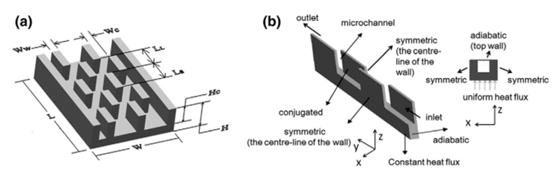
Figure 29.
Rectangular MCHS with Longitudinal fins by Dogan [16]. Reproduced with permission from Dogan [16]; published by Electronic materials, 2024.
Figure 30.
Rectangular MCHS with dimple and pin-fin by Ping Li [59]. Reproduced with permission from Ping Li [59]; published by Electronic materials, 2024.
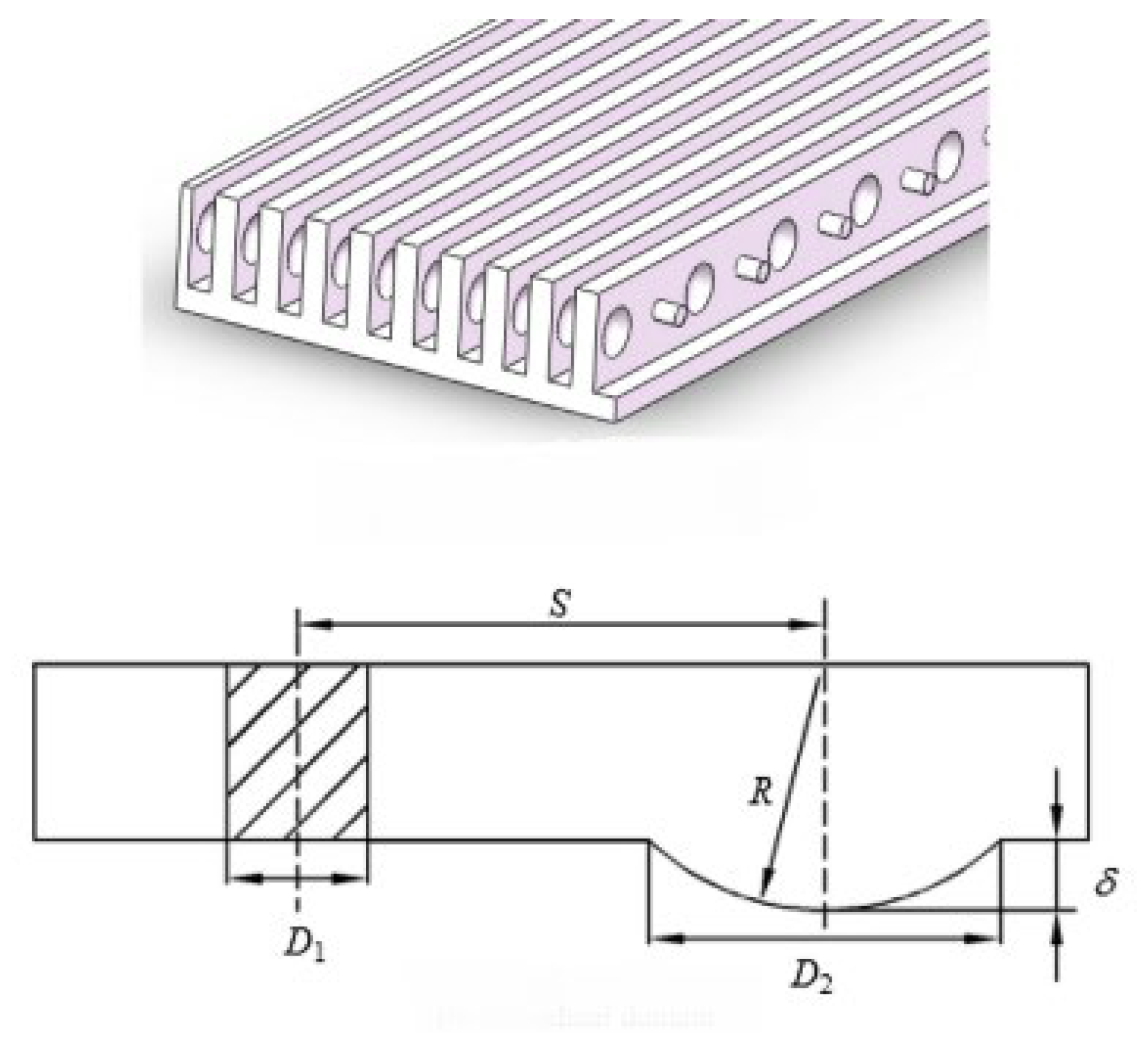
Figure 31.
MCHS with semi-closed omega-shaped configuration by Daxiang Deng. et al. [62]. Reproduced with permission from Daxiang Deng. et al. [62]; published by Electronic materials, 2024.
2.2.7. Thermal Enhancement Techniques and Analysis for Smooth Microchannel Heat Sinks
In this section the other work related to primary flow channel without using any obstructions would be demonstrated. Weilin Qu et al. [20] have examined the heat transfer and the properties related to pressure drop of a single-phase microchannel heat sink. They noticed the laminar to turbulent flow transition within the Reynold number ranging from 139 to1672. The other parameter which has also been investigated was the Nusselt number. At the bottom wall of channel the Nusselt number was lower as compared to the channel side wall. A theoretical and experimental investigation of gas flow in the microchannel was performed by John C. Harley. et al. [70] concluded that the Knudsen number was less than 0.38 and the data were within 8% of theoretical predictions of the friction constant. Through a triangular microchannel of silicon the characteristics of heat transfer of water as a coolant were evaluated by I. Tiselj. et al. [71].They concluded that the water temperature as well as the temperature of the heated wall do not change linearly along the channel. Todd M. Harms et al. [72] studied single-phase forced convection of two configurations in a deep rectangular microchannel. They found that their microchannel system established for developing laminar flow outperforms the comparable single-channel system designed for turbulent flow and lowering the channel width and enhancing the channel depth provides better flow and good performance in terms of heat transfer. K.C. Toh. et al. [73] investigated fluid flow and heat transfer characteristics in a microchannel heat sink. They observed that the cold flow friction factor corresponds to the fully developed friction factor with parameters of the microchannel heat sink by decreasing Reynolds numbers, there is a reduction in friction factor with heating. Gabriel Gamrat et al. [74] investigated the effects of entrance and conduction on liquid flow in laminar region of a microchannel heat sink. They found that with the reduction in channel spacing from 1mm to 0.1mm had no effect on heat transfer properties and the effects of conduction would be stronger in low Reynolds number range.
The enhancement in heat transfer using redevelopment of thermal boundary layer was studied by J.L. Xu et al. [75]. They found that the increase in Nusselt numbers and shorter effective flow length at the microchannel heat sink thermal entrance zone has improved the heat transfer and caused significantly reduced pressure drops. The effect of geometrical parameters on the single-phase forced convective heat transfer in microchannel heat sinks was investigated by X. F. Peng et al. [76] They concluded that the properties of liquid convection are different from those of channels of a similar size, changing from a laminar flow regime at Re 300 to a completely turbulent flow regime at about Re 1000. Amy Rachel Betz et al. [77] found that segmented flow increases the Nusselt number by over 100%, reaching values of 10.1–22.9, and enhances heat transfer by 140%, compared to single-phase flow conditions. Azad Qazi Zade et al. [78] explored the effects of growing gaseous slip flow in micro-channels. Their findings indicated that the Nusselt number experienced changes of 15% in the fully-developed region and 20% in the entry region.
Baoqing Deng.et al [79] studied an enhanced porous medium model for the microchannel heat sink and extended the porous medium to the substrate. They also derived an analytical solution for the hydrodynamically and thermal fully developed flow. Kuppusamay, N.R et al. [92] examined the hydrodynamic performance of single-phase flow in array mini channels and discovered that the inlet plenum design for fluid entry improved flow distribution, the maximum discrepancy was less than 3.4%, and the transition from laminar flow occurs early at Re=1100. The effect of the two-phase flow on the thermal performance of the heat sink was studied by Tom Saenen.et al [80] and they verified the numerical code using the method of manufactured solutions and revealed that numerical order in space and time is consistent with the expected values from theory, second-order, and first-order, respectively. Yang. Et al [81] studied single phase hybrid microchannel heat sink with secondary oblique channels. They found that pressure drop reduced by 11% and thermal resistance reduced by 24% compared to smooth MCHS. They concluded that their suggested heat sink exhibited maximum chip temperature of 53oC with pressure drop of 3.77kPa. Zhi-Qiang Yu. et al. [82] conducted a comprehensive review on microchannel heat sink for electronic cooling applications. They summarized heat transfer applications, coolants, materials and performance of different channels with single phase and phase change flow in MCHS. Min Yang.et al [83] studied Pareto frontier for performance evaluation of MCHS configurations. They used pumping power and thermal resistance as a performance evaluation criteria. They concluded that hybrid MCHS exhibit lower pumping power and superior thermal performance. Table 6 shows work of different researchers on the optimization of microchannel heat sink and Table 7 discusses research done on microchannel heat sink without any flow obstruction.
Saenen, T. et al. [80] examined the MCHS using a cooling system with two-phase flow. Simple algorithms were used for the results prediction. The equations were solved using finite volume discretization, and the numerical codes were validated using experimental results. The correlation between findings was good and accurately predicted the model of system. Sharma. et al. [84] analyzed the fluid flow heat transfer properties in a microchannel heat sink using hot water as a coolant for an even hotter electronic chip. There was laminar flow inside of the channel and turbulent flow at the inlet and outlet manifolds of the heat sink. For the analysis of local entropy generation Reynolds number 2400 and high Reynolds number 11200 were used. The results concluded that due to viscous dissipation there is an increase in Reynolds number and in the entropy generation. Hot water as coolant reduces entropy generation. The effect of substrate thickness on heat transfer in MCHS was numerically examined by Ali Kosar [14]. Different materials including Polyimide, Silica Glass, Quartz, Steel, Silicon, and Copper of different substrate thicknesses, t=100µm- 1000µm, are analyzed. Nusselt number was related as a function of Biot number Bi, and relative conductivity k. The Nusselt number for Silica glass is 50% higher than Polyimide MCHS. Zhigang. et al. [85] used the Reynolds number ranging from 101-1775 to analyze the effect of thermal properties variations on heat transfer. Several methodologies, as well as experimental results, correlations, and data from the simplified theoretical solution, are used to compare the obtained local and average flow and heat transfer properties. The forced convection in microchannels was analyzed by Chien-Hsin Chen [19]. Numerical simulations were made on the fluid-saturated porous medium modeled microchannel. The results concluded that with increasing aspect ratio, and porosity overall Nusselt number increased. Chih -Wei Chen. et al. [86] used the simulated annealing approach. Three design variables including channel height, fin width, and channel width were analyzed to find the optimal performance of the microchannel heat sink.
Figure 33.
Rectangular Microchannel by J.H. Ryu. et al. [56]. Reproduced with permission from J.H. Ryu. et al. [56]; published by Electronic materials, 2024.
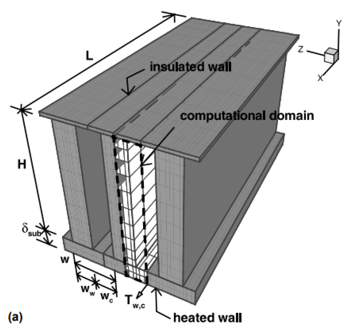
Figure 34.
C Rectangular Microchannel by K.C. Toh. et al. [73]. Reproduced with permission from K.C. Toh. et al. [73]; published by Electronic materials, 2024.
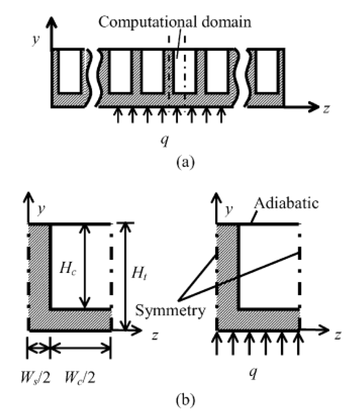
Figure 35.
Rectangular Microchannel by J.L. Xu. et al. [75]. Reproduced with permission from J.L. Xu. et al. [75]; published by Electronic materials, 2024.
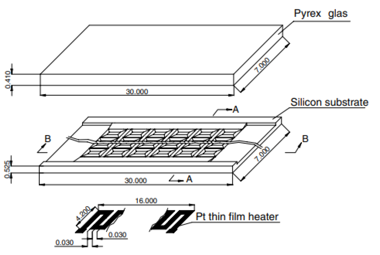
Figure 36.
Rectangular Microchannel by Amy Rachel Betz. et al. [77] Reproduced with permission from Amy Rachel Betz. et al. [77]; published by Electronic materials, 2024.
Figure 37.
Array Minichannel by Mohammed.H. et al. [64]. Reproduced with permission from Mohammed.H. et al. [64]; published by Electronic materials, 2024.
Figure 38.
MCHS with two-phase flow byTom Saenen. et al. [80].
Figure 38.
MCHS with two-phase flow byTom Saenen. et al. [80].
Figure 39.
Microchannel heat sink with manifold and oblique channels by Min Yang. Et al [83]. Reproduced with permission from Min Yang. Et al [83]; published by Electronic materials, 2024.
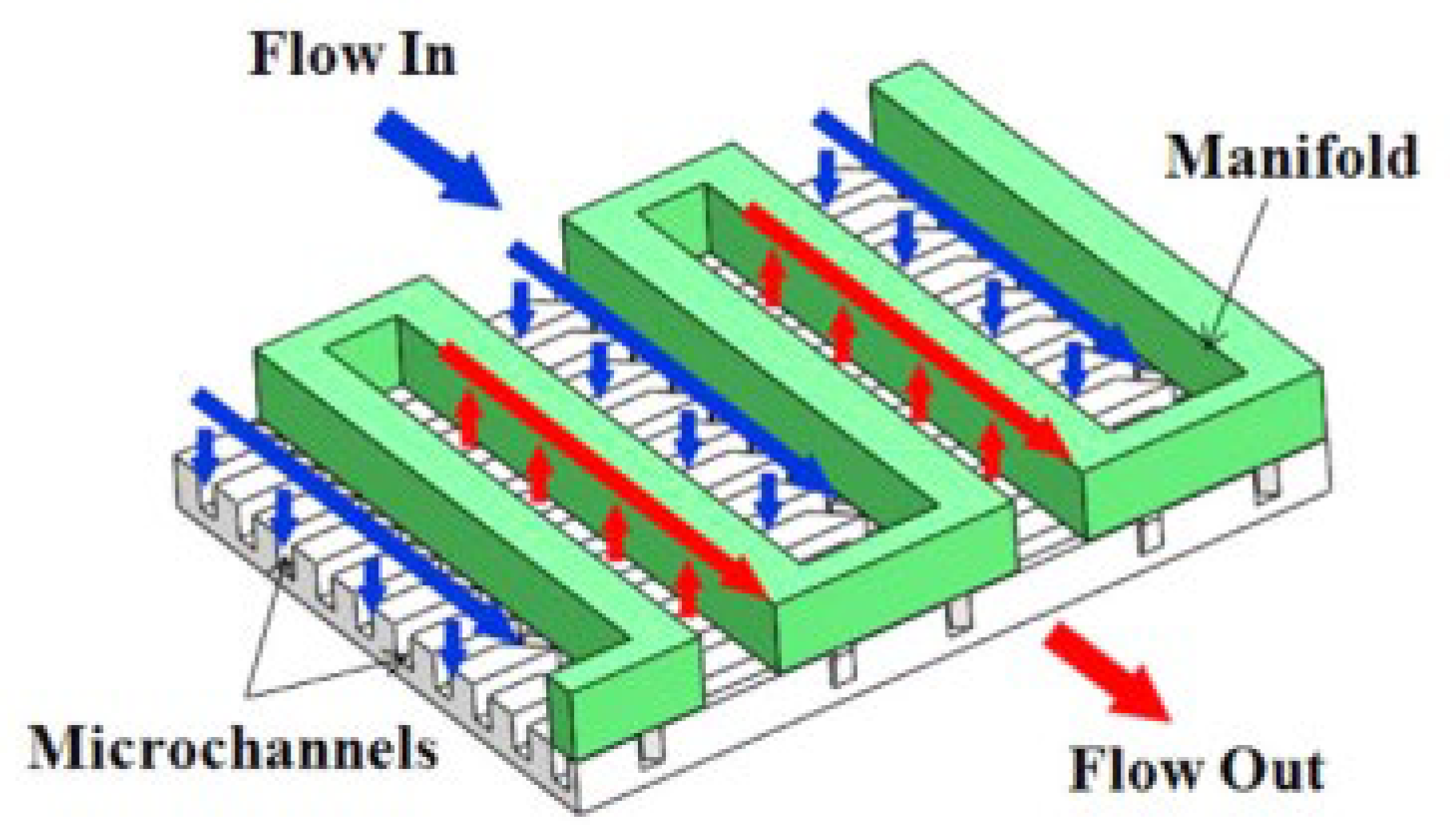
Table 8 shows other techniques used for microchannel heat sink modeling and analysis.
Figure 40.
Rectangular MCHS by Peng. X. et al. [76]. Reproduced with permission from Peng. X. et al. [76]; published by Electronic materials, 2024.
Figure 41.
Rectangular MCHS with Porous medium by Tsung-Hsun Tsai. et al. [117]. Reproduced with permission from Tsung-Hsun Tsai. et al. [117]; published by Electronic materials, 2024.
Figure 42.
Rectangular microchannels of Copper, silicon, and stainless steel by Zhigang.et al [85]. Reproduced with permission from Zhigang.et al [85]; published by Electronic materials, 2024.
Figure 43.
CRectangular MCHS using water-air coolant byZade. A.Q. et al. [78]. Reproduced with permission from Zade. A.Q. et al. [78]; published by Electronic materials, 2024.
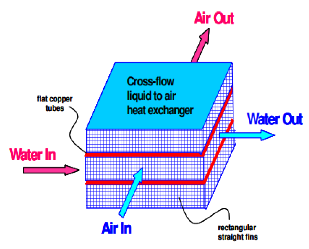
Figure 44.
Rectangular Microchannel by Chien-Hsin Chen. et al. [19]. Reproduced with permission from Chien-Hsin Chen. et al. [19]; published by Electronic materials, 2024.
2.2.8. Induced Secondary Flow
This section covers secondary channels’ potential to improve the effectiveness of heat transfer in microchannel heat sinks. Secondary channels are smaller channels that are located inside the main microchannel. The secondary flow created by these channels increases the microchannel heat sink’s ability to transfer heat more effectivly. Secondary channels decreases the thermal boundary layers thickness, improve the surface area available for heat transfer, and promote better flow mixing using secondary flow streams. For use in microchannel heat sinks, secondary channels can be arranged in a variety of methods. One common arrangement is straight parallel channels that are positioned transverse to the main microchannel.The secondary passages create vortices in the flow, which enhance mixing and heat transfer. The addition of curved secondary channels provides various arrangements, such as a serpentine or meandering design, to the main microchannel. These curved channels create secondary flows that increase heat transfer efficiency and decrease the thermal boundary layer thickness. For optimal heat transfer efficiency, the size, curvature, and spacing of the curved channels can be adjusted. Perforated plates are another secondary channel design for microchannel heat sinks. It is filled with thin plates with tiny holes, called perforated plates, which make up the primary microchannel. The perforated plates induce turbulence in flow, improving heat transfer. For multilayer arrangements, MCHS can also include secondary channels. Secondary channels are positioned in between layers of microchannels that are piled on top of one another. Secondary channels assist microchannel heat sinks to transfer more heat because they produce secondary flows that improve heat transfer. One of the challenges associated with the utilization of secondary channels is the fabrication of secondary channels with high precision and accuracy. To accomplish the intended heat transfer enhancement, the secondary channels must be positioned with a high degree of precision and accuracy. High precision and accuracy microchannel fabrication often costs a lot and calls for sophisticated fabrication methods like photolithography and MEMS technology. (Bahrami, 2011).
Another challenge is pressure losses occurring due to the use of secondary channels. The performance of the flow rate and heat transfer may be impacted by the pressure drop in the channel, which may raise the overall pressure losses. To obtain the best overall performance, the optimised design with secondary channels should balance the pressure losses with the improvement of heat transfer. Also, secondary channels can lead to flow maldistribution and thermal nonuniformity in microchannel heat sinks. The secondary channels can induce complex flow patterns, resulting in maldistributed flow patterns, resulting in non-uniform heat transfer and temperature distribution. Using secondary channels in microchannel heat sinks presents several challenges in terms of fabrication, pressure loss, flow maldistribution, and thermal non-uniformity; therefore, the best design with secondary channels should consider these issues to achieve the best overall performance. Wan Mohd. et al. [8] examined the effectiveness of the secondary channel numerically at Reynolds number (Re) ranging from 100 to 450. A comparison analysis of related geometries is used to examine the efficiency of suggested MCHS with rectangular ribs, triangular cavities, and micro channels with rectangular ribs and triangular cavities The outcome shows that the suggested design when compared to other designs, has an exceptional overall performance because of the collective effects of thermal boundary layer re-development and mixing of flow in the main channel. Ghani. et al. [101] conducted a numerical simulation at Reynolds numbers ranging from 100 to 800 to investigate properties heat transfer and fluid flow in MCHS having cavities in sinusoidal shape and rectangular ribs. The optimized results showed that the suggested geometry with cavities in sinusoidal shape and rectangular ribs with parameters of relative cavity amplitude 0.15, relative rib width 0.3 and relative rib length 0.5 has the best overall performance of 1.85.
The heat transfer of microchannel heat sinks with periodic expansion–constriction cross sections were investigated both experimentally and numerically by Lei chai. et al. [88].Results showed that in comparison with the straight rectangular MCHS, the pressure drop in the suggested new heat sink is lower when Re < 300, but increases rapidly and was higher at 300 < Re < 750, heat transfer is significant due to the greater mixing of the cooling fluid. Memon. et al. [82] studied computationally modeled secondary flow channels in different orientations rectangular and trapezoidal. It is evident from results that the trapezoidal microchannel heat sink had a higher average Nusselt number and enhanced heat transfer coefficient to 64% as compared to the conventional parallel orientation without secondary flow. M. Yang et al. [90] optimized microchannel heat sinks with secondary oblique channels, achieving an 18.83% reduction in thermal resistance compared to traditional manifold MCHS while maintaining similar pressure levels. W.Gao. et al. [91] suggested a multi-jet impingement heat sink with trapezoidal fins and secondary channels via using numerical simulations. The results predicted that the suggested heat sink performs well, with good heat transfer enhancment. N.R Kuppusamy. et al. [92] employed Secondary flow in (MCHS) in alternating orientation by introducing slanted passage in the channel wall. Due to disruption in the hydrodynamic boundary layer and redevelopment at the leading edge of the following wall, the results showed that the overall performance of suggested MCHS increased by 1.46 times and thermal resistance also reduced. The thermo hydraulic attributes of a Nano fluid containing graphene–silver nanoparticles in a MCHS having ribs and secondary channels were evaluated by Bahirae. et al. [93]. The use of auxiliary channels, ribs, and nano fluid greatly enhanced performance. The average convective heat transfer coefficient increases by 17% at Re=100 when the concentration rises from 0 to 0.1% with an increase in Reynolds number.
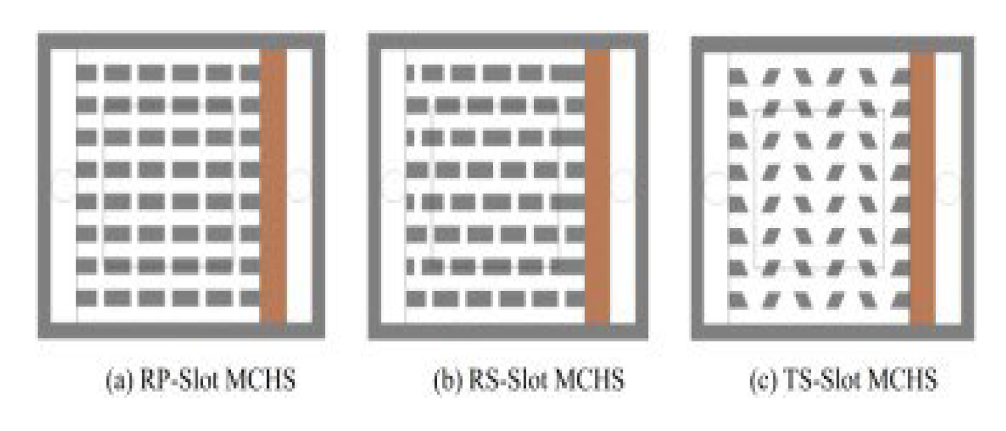
Wang.et al [94] By incorporating transverse gaps into the ribs, wavy configurations with secondary branches were created for the investigated micro channel heat sinks, which had symmetric and parallel wavy micro channels at Reynolds numbers ranging from 50 to 700. The new hybrid design’s performance was evaluated against the original wavy configurations. The findings showed that the new hybrid MCHS performs better overall with a small increase in pressure loss.Ma. D. et al. [95] developed wavy Sinusoidal microchannels with secondary channels. The testing findings demonstrated that the proposed micro channels could provide superior heat elimination performance than the standard rectangular micro channels because of the existence of the secondary channel. A new Microchannel Heat Sink (MCHS) design with cavities in trapezoidal shape, secondary channels, and ribs was proposed by SA Razali. et al. [96]. Heat transfer characteristics and fluid flow were numerically analyzed for Reynold numbers ranging from 100 to 500. Four different microchannel heat sink geometries had been taken under study. They found that the secondary MCHS with ribs in rectangular shape is the best-proposed design compared to the other four geometries, with a maximum performance factor of 1.78. Farzaneh. et al. [97] investigated the effect of branching to develop a system configuration that had minimum resistance to heat flow. According to the examined data, raising the number of branches lowers both temperature and pressure drop. According to experiments, when compared to case without a branch, one with more number of branches have greater heat transfer characteristics. Huang. et al. [98] numerically studied three types of MCHS for heat transfer characteristics, which were Parallel-Slot Rectangular Micro channel Heat Sink, Stagger-Slot Rectangular Micro channel Heat Sink, and Trapezoidal Stagger-Slot Micro channel Heat Sink. The findings demonstrated that the Trapezoidal Stagger-Slot MCHS was the best in terms of total heat transfer capabilities and thermal performance with non-changing pumping power since it has the lowest drop in pressure and the best heat transfer qualities. The oblique fin micro channel heat sink was experimentally investigated by Poh Seng Lee. et al. [99]. Due to the oblique fins there is also the introduction of secondary path for the flow. As a result the average Nusselt number has increased from 8.6 to 15.8 with reduction in the total thermal resistance.
Yan Fan et al. [100] numerically studied the heat transfer in laminar flow through novel cylindrical discrete oblique fin heat sinks. Their results revealed that the average Nusselt number increased by 73.5%, from 14.6 to 25.4, and the average convective thermal resistance decreased by 61%, from 0.075 °C/W to 0.029 °C/W, compared to smooth microchannel heat sinks (MCHS). Secondary channels reduce the thickness of the thermal boundary layers, increasing the surface area available for heat transfer, which promotes better flow mixing via secondary flow streams.In these micro channels with secondary flow, pressure drop is low at lower Reynolds numbers but increases with increasing Reynolds numbers [42]. Secondary flow decreases thermal resistance and increases channel transport efficiency [90]. Disruption in the boundary layer caused by secondary flow improves the fluid mixing thus increasing the Nusselt number.
Table 9 summarizes the use of secondary flows in microchannel heat sink improvement.
Figure 46.
Rectangular MCHS with ribs and cavities by Ghani. et al. [101]. Reproduced with permission from Ghani. et al. [101]; published by Electronic materials, 2024.
Figure 47.
Rectangular MCHS with triangular cavities by Lei Chai. et al. [42].
Figure 47.
Rectangular MCHS with triangular cavities by Lei Chai. et al. [42].
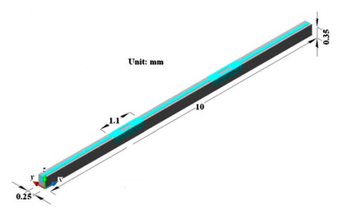
Figure 48.
Trapezoidal and Parallel Orientations rectangular MCHS by Memon. et al. [89]. Reproduced with permission from Memon. et al. [89]; published by Electronic materials, 2024.
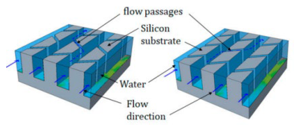
Figure 49.
Manifold MCHS with secondary oblique fin by yang. et al. [90]. Reproduced with permission from yang. et al. [90]; published by Electronic materials, 2024.
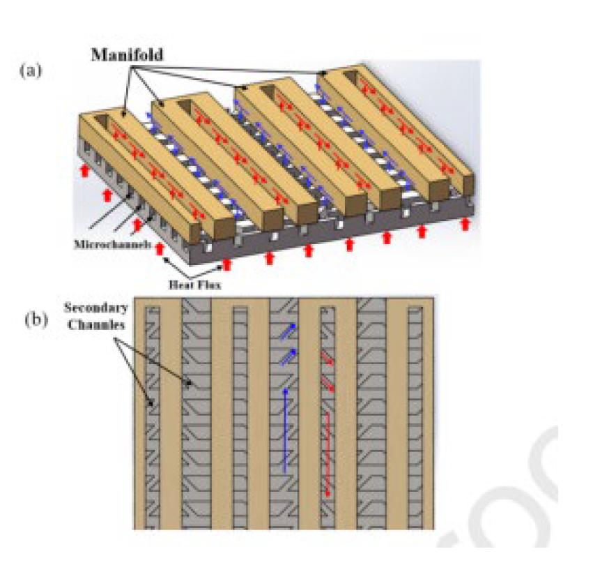
Figure 50.
Rectangular secondary flow MCHS byKuppusamay. et al. [92]. Reproduced with permission from Kuppusamay. et al. [92]; published by Electronic materials, 2024.
Figure 51.
MCHS with ribs and secondary channels by Bahirae. et al. [93]. Reproduced with permission from Bahirae. et al. [93]; published by Electronic materials, 2024.
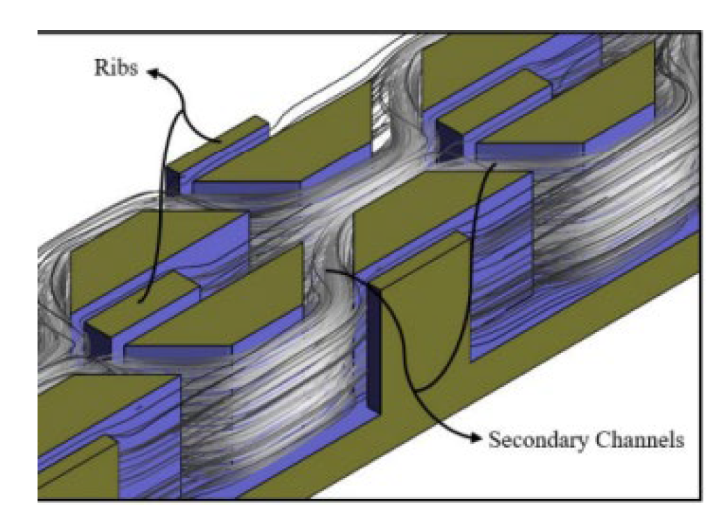
Figure 52.
Sinusoidal secondary flow MCHS by D.D.Ma. et al. [95]. Reproduced with permission from D.D.Ma. et al. [95]; published by Electronic materials, 2024.
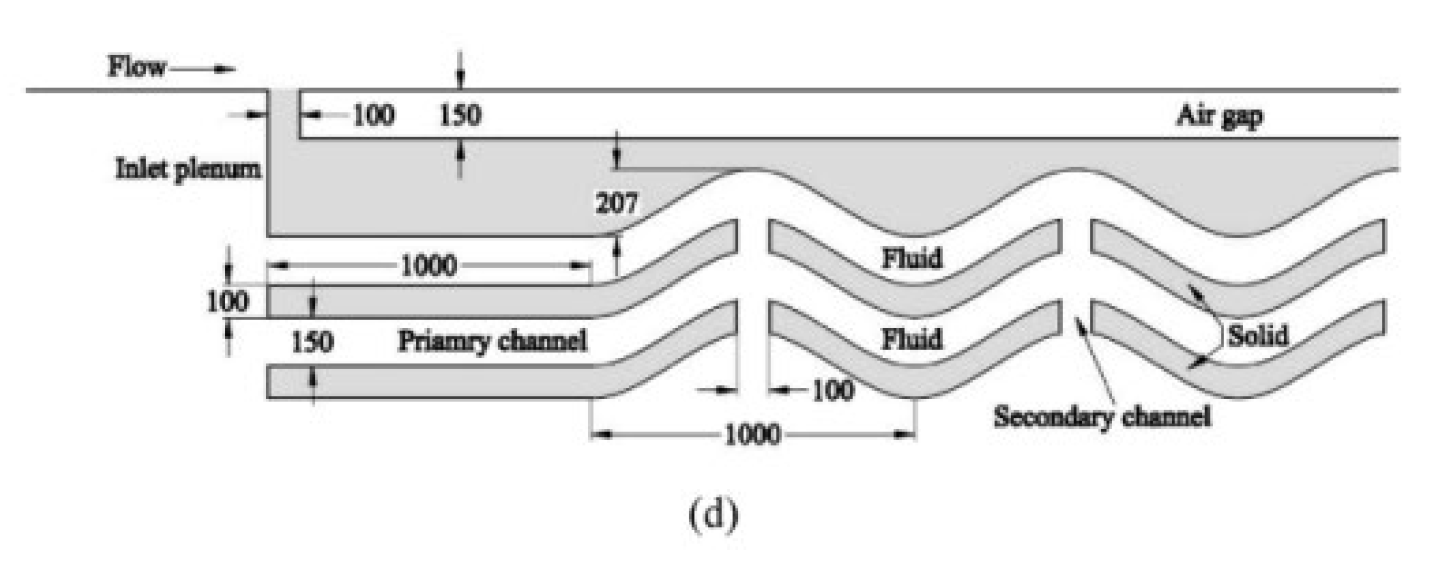
Figure 53.
C MCHS with ribs and secondary channels by SA Razali. et al. [96].
Figure 53.
C MCHS with ribs and secondary channels by SA Razali. et al. [96].
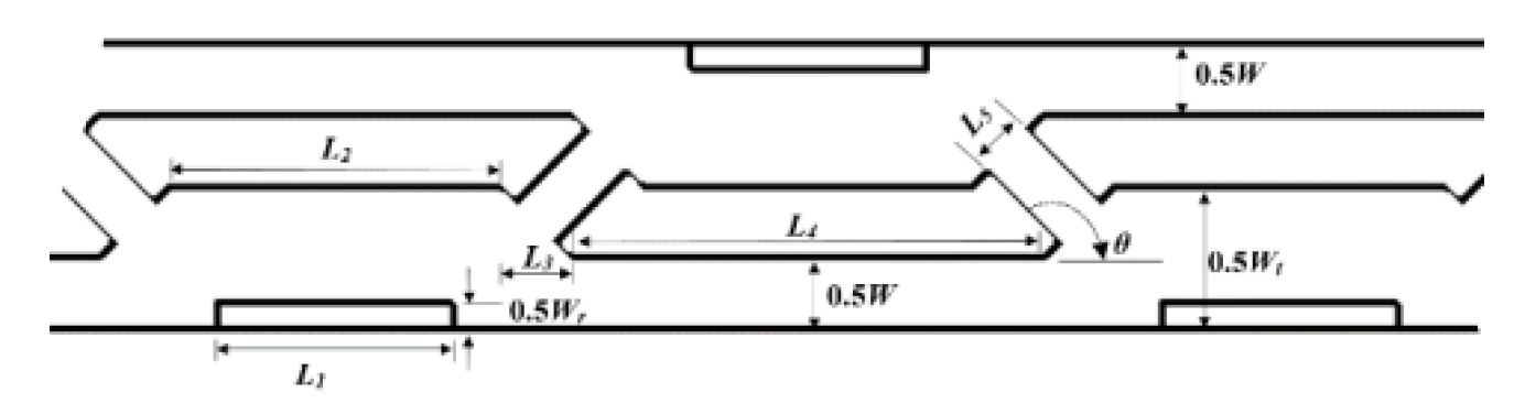
Figure 54.
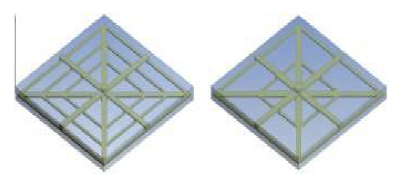
Square-shaped MCHS with one and two initial loops. by Farzaneh. et al. [97]. Reproduced with permission from Farzaneh. et al. [97]; published by Electronic materials, 2024.
2.2.9. Nano Fluids
The poor thermal conductivity of common fluids like water, ethylene glycol, or oil results in low heat transfer efficiency in MCHS. Nanoscale particles suspended in a basic fluid, like water or oil, make up nano-fluids. More heat dissipation from MCHS may arise from these nanoparticles’ increased thermal conductivity of the base fluid, whereas nanofluids can significantly increase heat transfer in microchannel heat sinks, their use is also limited by several limitations. Nanoparticle agglomeration and sedimentation will reduce the thermal conductivity of nanofluids and clog microchannels as they settle over time. This may affect the long-term stability of the nanofluid and reduce its heat transfer efficiency. CuO-water nanofluids were found to lose up to 30% of their thermal conductivity after 30 days as a result of agglomeration in a study by Lyu et al. [102] The higher density and viscosity of nanofluids compared to their base fluids causes greater pressure to drop in microchannels, which may increase pumping power requirements and limit the maximum flow rate.
S. Abubakar [103] investigated the impact of temperature on the micro channel heat sink with water and Fe3O4-H2O4 as fluids. To replicate conjugate heat transfer in a three-dimensional rectangular microchannel heat sink, a continuous heat flow of 9000000 W/m2 was applied to the top of the silicon heat sink. The presence of nanoparticles lowers the temperature of the surfaces as the particle volume % of Fe3O4-H2O4 grows due to its higher dynamic viscosity and lower heat capacity compared to pure water. When using Fe3O4-H2O4 as a working fluid with a volume fraction of 0.4 in comparison with pure water it shows 0.04% temperature reduction and there is direct relation between Nano particles concentration and temperature is setup. Three distinct nanofluids—ethylene glycol-based CuO, water-based CuO, and Al2O3—were used in study by A. Sivakumr et al. [104] to examine the thermal performance of a serpentine-shaped microchannel heat sink in the Reynolds number range of 100 to 1300. The results showed that, in comparison to their base fluids, the heat transfer coefficients of the nanofluids CuO/ethylene glycol and Al2O3/water are higher, and that the heat transfer coefficient of the nanofluid CuO/ethylene glycol is higher than the heat transfer coefficient of nanofluid CuO/water and Al2O3/water. L.snoussi. et al. [105] numerically studied laminar nanofluid flow in 3D rectangular copper MCHS and constant heat flux. It was discovered that the heat transfer coefficient increased by 14% at 2% Al2O3/water Nano fluid concentration. Additionally, 4% more heat is transferred when utilizing Cu-water than Al2O3-water, which may be a result of Cu-water’s better thermal conductivity. In the study by Sarafraz et al. [106], the heat transfer coefficient (HTC) values for CNT/water nanofluid were reported as follows: At a Reynolds number of 200, the HTC was 3870 W/m²·°C, and at 1100, it increased to 6100 W/m²·°C. For a mass concentration of 0.1% CNT, at a heat flux of 90 kW/m², the HTC was 3580 W/m²·°C, while for a 0.15% concentration, it was 4645 W/m²·°C. In an experimental study, MR Thansekhar et al. [107] examined the effects of nanofluids with volume concentrations of 0.1% and 0.25% in Al2O3/water and SiO2/water, as well as deionized water. The greatest heat transfer improvement achieved by the nanofluid Al2O3/water at a 0.25% volume concentration was 36.63% when compared to water. Al2O3/water outperformed SiO2/water Nano fluid in heat transfer because of the higher thermal conductivity of Al2O3 nanoparticles.
In double-layered MCHS, A.A.A. Arani et al. [108] examined the heat transfer properties of nanofluid water/single-wall carbon nanotubes at Reynolds numbers 500, 1000, and 2000. The effect of the proportion of nanoparticles in water-based nanofluid in a Newtonian suspension was explored for values of 0.04, 0.08, and 0. 0. Their findings revealed that the ratio of maximal to the lowest temperature difference for the microchannel’s bottom wall, as well as the thermal resistance ratio, decreased with increasing nanoparticle volume percentage and decreasing truncated length. Arabpour. A et al. [109] reported that MCHS cooled with SiO2 nanofluids had a thermal performance enhancement of 3580 to 4645 W/m²°C compared to water. The CCZ-HS showed a thermal performance improvement of 3580 to 4645 W/m²°C over the CZ-HS. R.Vinoth. et al. [7] examined the impact of channel cross section on an oblique finned MCHS’s heat transfer efficiency experimentally. nanofluid used was Al2O3/water with volume fraction of 0.25%.The three channel cross-sections of the oblique finned micro channels were square, semicircle, and trapezoidal. When nanoparticles are introduced to the base fluid, the rate of heat transmission increases by 4.6% when compared to water. It has been discovered that trapezoidal cross-section profiles are more effective than square and semicircle cross-section profiles in heat transmission and flow characteristics.
Abdollahi et al. [110] studied the heat transfer properties of a nanofluid flow by doing a three-dimensional numerical simulation of an interrupted MCHS. With an Al2O3/water coolant nanofluid, interrupted MCHS with ellipse and diamond ribs was taken into consideration. It was shown that Al2O3/water nanofluid may increase the Nusselt number by more than 30% at a volume fraction of 5% nanoparticles. Based on the comparison with an unbroken, pure water-cooled MCHS, the findings showed that elliptical rib MCHS with nanofluid can enhance microchannel performance. Using Al2O3 nanofluid combined with various base fluids, Altayyeb Alfaryajat al. [111] quantitatively examined the heat transfer properties in 3D rhombus MCHS. The Al2O3 content in these fluids was 4%, and the nanoparticle diameter is 25 nm. Al2O3-water was shown to have the lowest temperature, the best heat transfer properties, and the least amount of thermal resistance when compared to the other base fluids. MM Sarafraz et al. [112] evaluated the thermal performance of MCHS using Ag/water as a nanofluid by experimental means. The silver/water nanofluid was shown to have a greater heat transfer coefficient than the base fluid. The results showed that the heat transfer coefficient rose by 47% at a silver (Ag) to water ratio of 0.1. A novel multi-nozzle trapezoidal MCHS (MNT-MCHS) using Al2O3 and TiO2 as coolants was numerically investigated by Ngoctan tran. et al. [113]. The optimized findings indicated that higher thermal conductivities and bigger volume fractions of nanoparticles in nanofluids will result in better thermal performance than lower thermal conductivities and smaller volume fractions of nanoparticles in nanofluids. The thermal performance of single-walled carbon nanotubes (SWCNT) and multi-walled carbon nanotubes (MWCNT) distributed in the two base fluids of water and kerosene in a fractal microchannel was quantitatively examined by Zongjie Lyu et al. [102] at Reynolds numbers of 1500 to 3000. According to the study, at the same Re number and nanoparticle volume percent, the water-based nanofluid’s performance assessment criteria was four times higher than the kerosene-based nanofluid’s. As a result, it was advised to cool SWCNT nanoparticles in fractal silicon microchannels using water as the working fluid.
A.A Razali. et al. [115] examined the impact of heat transmission using both computational and experimental methods to Al2O3 nanofluids after used as working fluid in MCHS. When Al2O3 nano fluids were used instead of water, it had been found that the rate of heat transfer was greater. However, the Al2O3 particle structure tends to be more intact and the crystallite size increased after increasing the temperature in the microchannel, according to the X-ray diffraction method (XRD). In the study by AR Chabi et al. [116], they used CuO/water nanofluids with concentrations of 0.1% and 0.2% by volume to examine forced convective heat transfer in a microchannel heat sink (MCHS). The experimental results revealed that at a Reynolds number of 1150, the average heat transfer coefficient for 0.2 vol% CuO nanofluid was increased by approximately 7200 W/m²°C compared to deionized water. The top limits of the particle volume fraction for TiO2-water nanofluid heat transfer performance in MCHS were experimentally determined by Manay et al. [117]. Analysis was done on the impact of the Reynolds number ranging from 100-750 and particle volume percentage at constant microchannel height of 200mm on the parameters of heat transfer and pressure drop. Heat transfer was seen to be improved by the water-TiO2 nanofluid up to 2.0 vol% but declined after that point. Furthermore, the thermal resistance was computed, and it was shown that adding nanoparticles to the base fluid with an average diameter of less than 25 nm might lower the thermal resistance.
A numerical analysis of the performance of a nanofluid-cooled microchannel cardiac sink was conducted by Tsung-Hsun Tsai et al. [118]. Through the use of a porous media model, the velocity and temperature distributions within the MCHS were determined. Heat transmission between the working fluid and the MCHS increased significantly when this fluid was used. By increasing the aspect ratio and porosity from optimum values nanofluid did not decreases thermal resistance. Nanoparticles improve the thermal conductivity of conventional fluids like water or oils, in addition to their convective heat transfer coefficient, leading to increased heat dissipation from microchannels. However, these nanofluids have some disadvantages, including the fact that nanoparticles settle in the channel over time, creating an additional layer and increasing thermal resistance. The more dense nanofluids have a higher pressure drop and require more pumping power [102]. However, nanoparticles significantly enhance fluid heat transfer abilities, which is the main goal of microchannel heat sinks
Table 10 summarizes the data for use of nano fluids in microchannel heat sink.
Figure 56.
Truncated double-layer MCHS by AAA Arani. et al. [108]. Reproduced with permission from AAA Arani. et al. [108]; published by Electronic materials, 2024.
Figure 57.
Double layer MCHS by Arabpour, A.. et al. [109]. Reproduced with permission from Arabpour, A.. et al. [109]; published by Electronic materials, 2024.
Figure 58.
Multi nozzle trapezoidal MCHS by Ngoctan. et al. [113]. Reproduced with permission from Ngoctan. et al. [113]; published by Electronic materials, 2024.
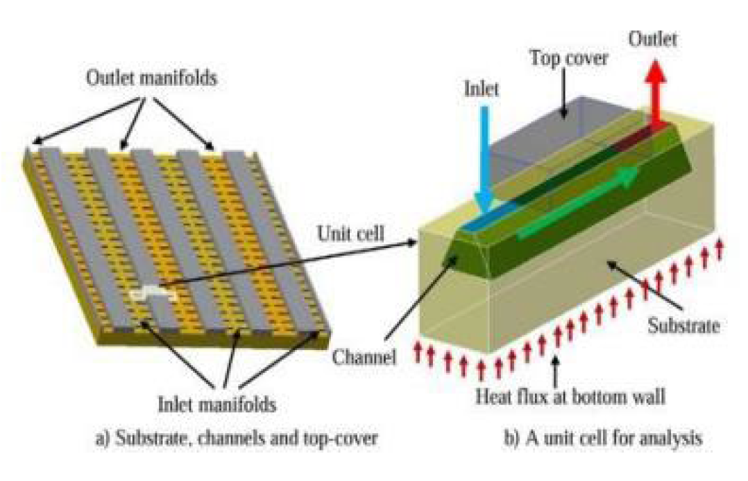
Figure 59.
Single-layer fractal MCHS by Zangonji. et al. [102].
Figure 59.
Single-layer fractal MCHS by Zangonji. et al. [102].
3. Conclusions
After conducting a thorough analysis of the available literature on MCHS, we conclude that shape and internal geometry of the cooling system are essential in enhancing its thermal performance. Different aspects such as temperature, flow uniformity, and heat transfer rate are influenced by the system’s geometry, as factors such as heat transfer coefficient, Nusselt number, and pressure drop determine the cooling system’s overall effectiveness.
- The outcomes of this review paper suggest that flow disruption techniques, optimization, secondary flows, and the use of nanofluids are all promising approaches for optimizing the thermal performance of MCHS.
- Flow disruption techniques such as ribs, grooves, cavities, dimples, and fins play an important role in enhancing the thermal performance of MCHS by disturbing the flow of the coolant and promoting better heat transfer between the coolant and the heat sink surface.
- Optimization is a crucial step in adjusting various design parameters of heat sink to obtain optimal performance, while using secondary flow promotes better mixing of fluid and enhances convective heat transfer.
- The use of nanofluids combined with flow disruption methods is also promising for enhancing MCHS thermal performance by boosting the convective heat transfer coefficient and promoting improved coolant mixing.
Overall, this critical review provides valuable insights into the impact of channel geometrical parameters on the efficiency of MCHS and highlights potential areas for future research. By optimizing the design and exploring innovative techniques, it is possible to improve the thermal performance of MCHS and unlock new possibilities for various applications.
4. Future Recommendations
Heat management has always been a major challenge because of how quickly electronic devices have evolved. Therefore, future studies should focus on the following areas:
- The optimization of different design MCHSs should be carried out to obtain their ideal geometries and enhance heat transfer efficiency. Future research should look at the use of multi-objective optimization approaches to balance various design features for microchannel heat sinks. We can achieve optimal solutions that go beyond conventional single-objective optimization techniques by taking into account several performance indicators at once, including pressure drop, heat transfer coefficient, and uniformity of temperature distributions.
- Future research should explore the concept or introduction of secondary flows in various designs of microchannel heat sinks, such as asymmetric, tapered, or curved channels. Researchers can find the best designs that best use secondary flows and enhance overall performance by carefully investigating the effects of various geometries on heat transfer characteristics.
- Investigate the manufacturing of, MCHS with unconventional fin geometry using advanced manufacturing techniques like 3D printing, and selective laser sintering. Complex and complicated fin structures that were previously challenging or impossible to construct using conventional techniques can now be made because of this technology. Researchers can investigate unconventional fin shapes, such as elliptical, triangular, and conical structures or customised arrangements, by using advanced manufacturing to improve heat transfer efficiency.
- Future studies should focus on developing nanoparticles with tailored properties specifically for microchannel heat sink applications. Explore more use of nanomaterials besides traditional metallic or oxides nanoparticles. Go through the possibility of adding carbon-based nanomaterials to nanofluids, such as carbon nanotubes or graphene. Evaluate their effect on thermal stability, heat transfer performance, and compatibility with microchannel heat sink materials.
- Study the advantages of including more than one layer in the microchannel structure. Investigate patterns with various channel widths, heights, or shapes across multiple layers. This can improve heat transfer uniformity, flow mixing, and efficient fluid distribution. Explore the effects of multiple-layer arrangements on pressure drop and overall thermal performance.
Author Contributions
KA, MAW and UG conceived and designed the study. M.A.W and U.G. collected data and organized the manuscript. UG, MAW, SS and MW wrote the first draft of manuscript. All authors contributed to final manuscript revision and approved the submitted version.
Acknowledgments
The authors acknowledge the support of UET Peshawar for providing the computational facilities to conduct this research.
Conflicts of Interest
The authors declare no conflict of interest.
References
- Furber, S. (2017). Microprocessors: the engines of the digital age. Proceedings of the Royal Society A: Mathematical, Physical and Engineering Science, 473(2199), 20160893. [CrossRef]
- Krazit, T. Intel unveils its first 10-nanometer Ice Lake processors. The Seattle Times. [cited 2019, August 1]. Intel Ice Lake Processors: Specs, Details, Release Date | WIRED.
- Hanafi, M. Z. M., Ismail, F. S., & Rosli, R. (2015). Radial plate fins heat sink model design and optimization. 2015 10th Asian Control Conference (ASCC). [CrossRef]
- Black, J. R. (1969). Electromigration—A brief survey and some recent results. IEEE Transactions on Electron Devices, 16(4), 338–347. [CrossRef]
- Deng, D., Xie, Y., Huang, Q., & Wan, W. (2017). On the flow boiling enhancement in interconnected reentrant microchannels. International Journal of Heat and Mass Transfer, 108, 453–467.
- Ghani, I. A., Sidik, N. A. C., & Kamaruzaman, N. (2017). Hydrothermal performance of microchannel heat sink: The effect of channel design. International Journal of Heat and Mass Transfer, 107, 21–44.
- Vinoth, R., & Senthil Kumar, D. (2017). Channel cross section effect on heat transfer performance of oblique finned microchannel heat sink. International Communications in Heat and Mass Transfer, 87, 270–276.
- Wan Mohd. Arif Aziz Japar , Nor Azwadi Che Sidik , Rahman Saidur , Yutaka Asako and Siti Nurul Akmal Yusof A review of passive methods in microchannel heat sink application through advanced geometric structure and nanofluids: Current advancements and challenges. 2020. 9(1): p. 1192-1216. [CrossRef]
- Khattak, Z., & Ali, H. M. (2019). Air cooled heat sink geometries subjected to forced flow: A critical review. International Journal of Heat and Mass Transfer, 130, 141–161.
- Adham, A., N. Mohd-Ghazali, and R. Ahmad, Thermal and hydrodynamic analysis of microchannel heat sinks: A review. Renewable and Sustainable Energy Reviews, 2013. 21: p. 614-622. [CrossRef]
- Tuckerman, D. B., & Pease, R. F. W. (1981). High-performance heat sinking for VLSI. IEEE Electron Device Letters, 2(5), 126–129. [CrossRef]
- Shizhong Zhang, Faraz Ahmad, Amjid Khan, Nisar Ali & Mohamed Badran et al. Performance improvement and thermodynamic assessment of microchannel heat sink with different types of ribs and cones, Scientific Reports volume 12, Article number: 10802 (2022).
- Nemati, H., A General Equation Based on Entropy Generation Minimization to Optimize Plate Fin Heat Sink. Engineering Journal, 2018. 22: p. 159-174. [CrossRef]
- Koşar, A,, Effect of substrate thickness and material on heat transfer in microchannel heat sinks. International Journal of Thermal Sciences, 2010. 49(4): p. 635-642.
- Woodcraft, A.L., Recommended values for the thermal conductivity of aluminium of different purities in the cryogenic to room temperature range, and a comparison with copper. Cryogenics, 2005. 45(9): p. 626-636.
- Dogan, M., & Sivrioglu, M., Experimental investigation of mixed convection heat transfer from longitudinal fins in a horizontal rectangular channel. 2010. 53(9-10): p. 2149-2158.
- Khan, M. N., & Karimi, M. N.: Journal of Process Mechanical Engineering, Analysis of heat transfer enhancement in microchannel by varying the height of pin fins at upstream and downstream region. 2021. 235(4): p. 758-767. [CrossRef]
- Yang, D., Wang, Y., Ding, G., Jin, Z., Zhao, J., & Wang, G. et al., Numerical and experimental analysis of cooling performance of single-phase array microchannel heat sinks with different pin-fin configurations. Applied Thermal Engineering, 2017. 112: p. 1547-1556.
- Chen, C.-H. (2007). Forced convection heat transfer in microchannel heat sinks. International Journal of Heat and Mass Transfer, 50(11-12), 2182–2189.
- Qu, W., & Mudawar, I., Experimental and numerical study of pressure drop and heat transfer in a single-phase micro-channel heat sink. 2002. 45(12): p. 2549-2565. [CrossRef]
- Zhai, Y. L., Xia, G. D., Liu, X. F., & Li, Y. F. (2014). Heat transfer in the microchannels with fan-shaped reentrant cavities and different ribs based on field synergy principle and entropy generation analysis. International Journal of Heat and Mass Transfer, 68, 224–233.
- Li, Y., Zhang, F., Sunden, B., & Xie, G. (2014). Laminar thermal performance of microchannel heat sinks with constructal vertical Y-shaped bifurcation plates. Applied Thermal Engineering, 73(1), 185–195.
- Go, J.S., Design of a microfin array heat sink using flow-induced vibration to enhance the heat transfer in the laminar flow regime. Sensors and Actuators A: Physical, 2003. 105(2): p. 201-210. [CrossRef]
- Hessami, M.-A., A. Berryman, and P. Bandopdhayay, Heat Transfer Enhancement in an Electrically Heated Horizontal Pipe Due to Flow Pulsation. Vol. 374. 2003. ISBN: 0-7918-3718-1.
- T. Krishnaveni, T. Renganathan, J. R. Picardo, and S. Pushpavanam et al., Numerical study of enhanced mixing in pressure-driven flows in microchannels using a spatially periodic electric field. Physical Review E, 2017. 96(3): p. 033117. [CrossRef]
- Morini, G. L., Lorenzini, M., Salvigni, S., & Spiga, M. (2006). Thermal performance of silicon micro heat-sinks with electrokinetically-drivenflows. International Journal of Thermal Sciences, 45(10), 955–961. [CrossRef]
- Han, Y., Lee, Y. J., & Zhang, X. (2013). Trapezoidal Microchannel Heat Sink With Pressure-Driven and Electro-Osmotic Flows for Microelectronic Cooling. IEEE Transactions on Components, Packaging and Manufacturing Technology, 3(11), 1851–1858. [CrossRef]
- Narrein, K., Sivasankaran, S., & Ganesan, P. (2016). Numerical investigation of two-phase laminar pulsating nanofluid flow in a helical microchannel. Numerical Heat Transfer, Part A: Applications, 69(8), 921–930. [CrossRef]
- Nandi, T. K., & Chattopadhyay, H. (2013). Numerical investigations of simultaneously developing flow in wavy microchannels under pulsating inlet flow condition. International Communications in Heat and Mass Transfer, 47, 27–31.
- Wang, G., Niu, D., Xie, F., Wang, Y., Zhao, X., & Ding, G. et al., Experimental and numerical investigation of a microchannel heat sink (MCHS) with micro-scale ribs and grooves for chip cooling. 2015. 85: p. 61-70.
- Xia, G. D., Jia, Y. T., Li, Y. F., Ma, D. D., & Cai, B., et al., Numerical simulation and multiobjective optimization of a microchannel heat sink with arc-shaped grooves and ribs. Numerical Heat Transfer, Part A: Applications, 2016: p. 1-16. [CrossRef]
- Ahmad, F., T.A. Cheema, and M.M.U. Rehman, Flow and heat transfer characteristics of microchannel heat sink with cylindrical ribs and cavities. Ahmad, F., T.A. Cheema, and M.M.U. Rehman, Fflow... - Google Scholar.
- Shahzad Ali, Faraz Ahmad, Muhammad Hassan, Zabdur Rehman, Abdul Wadood,Khurshid Ahmad and Herie Park, et al., Thermo-fluid characteristics of microchannel heat sink with multi-configuration NACA 2412 hydrofoil ribs. 2021. 9: p. 128407-128416.
- Khan, A. A., Kim, S.-M., & Kim, K.-Y. (2016). Performance Analysis of a Microchannel Heat Sink with Various Rib Configurations. Journal of Thermophysics and Heat Transfer, 30(4), 782–790. [CrossRef]
- Liu, Y.-H., Lo, Y.-H., Li, X.-X., & Huh, M. (2016). Heat Transfer and Friction in a Square Channel with Ribs and Grooves. Journal of Thermophysics and Heat Transfer, 30(1), 144–151. [CrossRef]
- LAU, S. C., KUKREJA, R. T., & MCMILLIN, R. D. (1992). Turbulent heat transfer in a square channel with staggered discrete ribs. Journal of Thermophysics and Heat Transfer, 6(1), 171–173.
- Zhang, S,Faraz Ahmad; Haseeb Ali; Sadiq Ali; Kareem Akhtar and Nisar Ali et al., Computational Study of Hydrothermal Performance of Microchannel Heat Sink With Trefoil Shape Ribs. 2022. 10: p. 74412-74424.
- Wang, G., Qian, N., & Ding, G. (2019). Heat transfer enhancement in microchannel heat sink with bidirectional rib. International Journal of Heat and Mass Transfer, 136, 597–609.
- Ali, S,Faraz Ahmed, Kareem Akhtar, Numan, Habib,Muhammad, Aamirkhaled Giasin, Ana Vafadar and Danil Yurievich Pimenov et al., Numerical investigation of microchannel heat sink with trefoil shape ribs. 2021. 14(20): p. 6764.
- Rehman, M. M. U., Cheema, T. A., Ahmad, F., Khan, M., & Abbas, A. (2019). Thermodynamic Assessment of Microchannel Heat Sinks with Novel Sidewall Ribs. Journal of Thermophysics and Heat Transfer, 1–12. [CrossRef]
- Ghani, I. A., Kamaruzaman, N., & Sidik, N. A. C. (2017). Heat transfer augmentation in a microchannel heat sink with sinusoidal cavities and rectangular ribs. International Journal of Heat and Mass Transfer, 108, 1969–1981.
- Chai, L., Xia, G., Zhou, M., Li, J., & Qi, J. (2013). Optimum thermal design of interrupted microchannel heat sink with rectangular ribs in the transverse microchambers. Applied Thermal Engineering, 51(1-2), 880–889.
- Li, Y. F., Xia, G. D., Ma, D. D., Jia, Y. T., & Wang, J. (2016). Characteristics of laminar flow and heat transfer in microchannel heat sink with triangular cavities and rectangular ribs. International Journal of Heat and Mass Transfer, 98, 17–28.
- Binuyo, A.S. Numerical Investigation Of Two-Phase Laminar Pulsating Nanofluid Flow In AnInterruptedMicrochannel Heat Sink. 2020. View article (google.com).
- Korichi, A., & Oufer, L. (2007). Heat transfer enhancement in oscillatory flow in channel with periodically upper and lower walls mounted obstacles. International Journal of Heat and Fluid Flow, 28(5), 1003–1012.
- Datta, A., Sharma, V., Sanyal, D., & Das, P. (2019). A conjugate heat transfer analysis of performance for rectangular microchannel with trapezoidal cavities and ribs. International Journal of Thermal Sciences, 138, 425–446.
- Ahmad, F., et al., Thermodynamic Analysis of Microchannel Heat Sink With Cylindrical Ribs and Cavities. Journal of Heat Transfer, 2020. 142(9). [CrossRef]
- Zhu, Q., Chang, K., Chen, J., Zhang, X., Xia, H., Zhang, H., … Jin, Y. (2020). Characteristics of heat transfer and fluid flow in microchannel heat sinks with rectangular grooves and different shaped ribs. Alexandria Engineering Journal. [CrossRef]
- Ahmed, H. E., & Ahmed, M. I. (2015). Optimum thermal design of triangular, trapezoidal and rectangular grooved microchannel heat sinks. International Communications in Heat and Mass Transfer, 66, 47–57.
- Kumar, P. (2019). Numerical investigation of fluid flow and heat transfer in trapezoidal microchannel with groove structure. International Journal of Thermal Sciences, 136, 33–43. [CrossRef]
- Xia, G., Chai, L., Wang, H., Zhou, M., & Cui, Z. (2011). Optimum thermal design of microchannel heat sink with triangular reentrant cavities. Applied Thermal Engineering, 31(6-7), 1208–1219.
- Herman, C., & Kang, E. (2002). Heat transfer enhancement in a grooved channel with curved vanes. International Journal of Heat and Mass Transfer, 45(18), 3741–3757. [CrossRef]
- Rehman, M. M. U., Cheema, T. A., Ahmad, F., Abbas, A., & Malik, M. S. (2019). Numerical investigation of heat transfer enhancement and fluid flow characteristics in a microchannel heat sink with different wall/design configurations of protrusions/dimples. Heat and Mass Transfer. [CrossRef]
- Xu, M., Lu, H., Gong, L., Chai, J. C., & Duan, X. (2016). Parametric numerical study of the flow and heat transfer in microchannel with dimples. International Communications in Heat and Mass Transfer, 76, 348–357.
- Chen, Y., Chew, Y. T., & Khoo, B. C. (2012). Enhancement of heat transfer in turbulent channel flow over dimpled surface. International Journal of Heat and Mass Transfer, 55(25-26), 8100–8121.
- Moon, H., T. O’connell, and B. Glezer. Channel height effect on heat transfer and friction in a dimpled passage. in Turbo Expo: Power for Land, Sea, and Air. 1999. American Society of Mechanical Engineers.ezer. [CrossRef]
- Gururatana, S.J.A.J.o.A.S., Numerical simulation of micro-channel heat sink with dimpled surfaces. 2012. 9(3): p. 399.
- Hong, F., & Cheng, P., Three dimensional numerical analyses and optimization of offsetstrip-fin microchannel heat sinks. 2009. 36(7): p. 651-656.
- Li, P., Luo, Y., Zhang, D., & Xie, Y. (2018). Flow and heat transfer characteristics and optimization study on the water-cooled microchannel heat sinks with dimple and pin-fin. International Journal of Heat and Mass Transfer, 119, 152–162.
- Wazir, M.A., et al., Thermal enhancement of microchannel heat sink using pin-fin configurations and geometric optimization. Engineering Research Express, 2024. DOI.
- Chu, J.-C., et al., Heat transfer for water flow in triangular silicon microchannels. 2008. 3(3): p. 410-420. [CrossRef]
- Deng, D., Wan, W., Tang, Y., Shao, H., & Huang, Y. (2015). Experimental and numerical study of thermal enhancement in reentrant copper microchannels. International Journal of Heat and Mass Transfer, 91, 656–670.
- Wu, H. ., & Cheng, P. (2003). An experimental study of convective heat transfer in silicon microchannels with different surface conditions. International Journal of Heat and Mass Transfer, 46(14), 2547–2556. [CrossRef]
- Mohammed, H., et al., Numerical simulation of heat transfer enhancement in wavy microchannel heat sink. 2011. 38(1): p. 63-68.
- Gunnasegaran, P., et al., The effect of geometrical parameters on heat transfer characteristics of microchannels heat sink with different shapes. 2010. 37(8): p. 1078-1086.
- Ghaedamini, H., P.S. Lee, and C.J. Teo, Developing forced convection in converging–diverging microchannels. International Journal of Heat and Mass Transfer, 2013. 65: p. 491-499.
- Peng, X.F., G.P. Peterson, and B.X. Wang, Heat transfer characteristics of water flowing through microchannels. Experimental Heat Transfer, 1994. 7(4): p. 265-283. [CrossRef]
- Wang, X.-Q., A.S. Mujumdar, and C.J.I.J.o.T.S. Yap, Thermal characteristics of tree-shaped microchannel nets for cooling of a rectangular heat sink. 2006. 45(11): p. 1103-1112. [CrossRef]
- McHale, J. P., & Garimella, S. V. (2010). Heat transfer in trapezoidal microchannels of various aspect ratios. International Journal of Heat and Mass Transfer, 53(1-3), 365–375.
- Harley, J.C., et al., Gas flow in micro-channels. Journal of Fluid Mechanics, 1995. 284: p. 257-274.
- Tiselj, I., Hetsroni, G., Mavko, B., Mosyak, A., Pogrebnyak, E., & Segal, Z. (2004). Effect of axial conduction on the heat transfer in micro-channels. International Journal of Heat and Mass Transfer, 47(12-13), 2551–2565.
- Harms, T.M., M.J. Kazmierczak, and F.M. Gerner, Developing convective heat transfer in deep rectangular microchannels. International Journal of Heat and Fluid Flow, 1999. 20(2): p. 149-157. [CrossRef]
- Toh, K.C., X.Y. Chen, and J.C. Chai, Numerical computation of fluid flow and heat transfer in microchannels. International Journal of Heat and Mass Transfer, 2002. 45(26): p. 5133-5141. [CrossRef]
- Gamrat, G., et al., Conduction and entrance effects on laminar liquid flow and heat transfer in rectangular microchannels. 2005. 48(14): p. 2943-2954.
- Xu, J. L., Gan, Y. H., Zhang, D. C., & Li, X. H. (2005). Microscale heat transfer enhancement using thermal boundary layer redeveloping concept. International Journal of Heat and Mass Transfer, 48(9), 1662–1674.
- Peng, X., G.J.I.J.o.H. Peterson, and M. Transfer, The effect of thermofluid and geometrical parameters on convection of liquids through rectangular microchannels. 1995. 38(4): p. 755-758. [CrossRef]
- Betz, A. R., & Attinger, D. (2010). Can segmented flow enhance heat transfer in microchannel heat sinks? International Journal of Heat and Mass Transfer, 53(19-20), 3683–3691.
- Zade, A.Q., et al., Heat transfer characteristics of developing gaseous slip-flow in rectangular microchannels with variable physical properties. 2011. 32(1): p. 117-127.
- Deng, B., Y. Qiu, and C.N.J.A.t.e. Kim, An improved porous medium model for microchannel heat sinks. 2010. 30(16): p. 2512-2517.76.
- Saenen, T. and M.J.I.j.o.t.s. Baelmans, Numerical model of a two-phase microchannel heat sink electronics cooling system. 2012. 59: p. 214-223.
- Yang, M., Li, M.-T., Hua, Y.-C., Wang, W., & Cao, B.-Y. (2020). Experimental study on single-phase hybrid microchannel cooling using HFE-7100 for liquid-cooled chips. International Journal of Heat and Mass Transfer, 160, 120230.
- Zhi-Qiang Yu, Mo-Tong Li and Bing-Yang Cao, International Journal of Extreme Manufacturing, Volume 6, Number 2.
- Min Yang , Mo-Tong Li , Xin-Gang Yu, Lei Huang , Hong-Yang Zheng , Jian-Yin Miao and Bing-Yang Cao, Applied Thermal Engineering Volume 212, 25 July 2022, 118550. [CrossRef]
- Sharma, C.S., et al., Thermofluidics and energetics of a manifold microchannel heat sink for electronics with recovered hot water as working fluid. 2013. 58(1-2): p. 135-151.
- Li, Z., et al., Effects of thermal property variations on the liquid flow and heat transfer in microchannel heat sinks. 2007. 27(17-18): p. 2803-2814.
- Chen, C.-W., et al., Optimum thermal design of microchannel heat sinks by the simulated annealing method. 2008. 35(8): p. 980-984.
- Japar, W. M. A. A., Sidik, N. A. C., & Mat, S. (2018). A comprehensive study on heat transfer enhancement in microchannel heat sink with secondary channel. International Communications in Heat and Mass Transfer, 99, 62–81.
- Chai, L., et al., Heat transfer enhancement in microchannel heat sinks with periodic expansion–constriction cross-sections. 2013. 62: p. 741-75182.
- Memon, S.A., et al., Hydrothermal investigation of a microchannel heat sink using secondary flows in trapezoidal and parallel orientations. 2020. 13(21): p. 5616.
- Yang, M., & Cao, B.-Y. (2020). Multi-objective optimization of a hybrid microchannel heat sink combining manifold concept with secondary channels. Applied Thermal Engineering, 115592.
- Gao, W., Zhang, J. F., Qu, Z. G., & Tao, W. Q. (2021). Numerical investigations of heat transfer in hybrid microchannel heat sink with multi-jet impinging and trapezoidal fins. International Journal of Thermal Sciences, 164, 106902.
- Raja Kuppusamy, N., Saidur, R., Ghazali, N. N. N., & Mohammed, H. A.., et al., Numerical study of thermal enhancement in micro channel heat sink with secondary flow. 2014. 78: p. 216-223.
- Bahiraei, M., Jamshidmofid, M., & Goodarzi, M., Efficacy of a hybrid nanofluid in a new microchannel heat sink equipped with both secondary channels and ribs. 2019. 273: p. 88-98.
- Wang, S.-L., Zhu, J.-F., An, D., Zhang, B.-X., Chen, L.-Y., Yang, Y.-R., … Wang, X.-D. (2022). Heat transfer enhancement of symmetric and parallel wavy microchannel heat sinks with secondary branch design. International Journal of Thermal Sciences, 171, 107229.
- Ma, D., Y. Tang, and G.J.A.T.E. Xia, Experimental investigation of flow boiling performance in sinusoidal wavy microchannels with secondary channels. 2021. 199: p. 117502.
- Razali, S., N. Sidik, and S. Yusof. Numerical studies of fluid flow and heat transfer in microchannel heat sink with trapezoidal cavities, ribs and secondary channel. in Journal of Physics: Conference Series. 2021. DOI.
- Farzaneh, M., Salimpour, M. R., & Tavakoli, M. R. (2016). Design of bifurcating microchannels with/without loops for cooling of square-shaped electronic components. Applied Thermal Engineering, 108, 581–595.
- Huang, S., et al., Thermal performance and structure optimization for slotted microchannel heat sink. 2017. 115: p. 1266-1276.
- Poh Seng Lee, Y.-J., P.-S. Lee, and S.-K. Chou. Experimental investigation of oblique finned microchannel heat sink+. in 2010 12th IEEE Intersociety Conference on Thermal and Thermomechanical Phenomena in Electronic Systems. 2010. IEEE. [CrossRef]
- Fan, Y., et al. Numerical simulations of forced convection in novel cylindrical oblique-finned heat sink. in 2011 IEEE 13th Electronics Packaging Technology Conference. 2011. IEEE. [CrossRef]
- Ghani, I. A., Sidik, N. A. C., Mamat, R., Najafi, G., Ken, T. L., Asako, Y., & Japar, W. M. A. A. (2017). Heat transfer enhancement in microchannel heat sink using hybrid technique of ribs and secondary channels. International Journal of Heat and Mass Transfer, 114, 640–655.
- Lyu, Z., Pourfattah, F., Arani, A. A. A., Asadi, A., & Foong, L. K et al., On the Thermal Performance of a Fractal Microchannel Subjected to Water and Kerosene Carbon Nanotube Nanofluid. Scientific Reports, 2020. 10(1): p. 7243. [CrossRef]
- Abubakar, S., C.N. Azwadi, and A.J.J.A.R.M.S. Ahmad, The use of Fe3O4-H2O4 nanofluid for heat transfer enhancement in rectangular microchannel heatsink. 2016. 23: p. 15-24.
- Sivakumar, A., Alagumurthi, N., & Senthilvelan, T. (2015). Effect of Serpentine Grooves on Heat Transfer Characteristics of Microchannel Heat Sink with Different Nanofluids. Heat Transfer-Asian Research, 46(3), 201–217. [CrossRef]
- Snoussi, L., et al., Numerical simulation of nanofluids for improved cooling efficiency in a 3D copper microchannel heat sink (MCHS). Physics and Chemistry of Liquids, 2018. 56(3): p. 311-331. [CrossRef]
- Sarafraz, M. M., Nikkhah, V., Nakhjavani, M., & Arya, A.., et al., Fouling formation and thermal performance of aqueous carbon nanotube nanofluid in a heat sink with rectangular parallel microchannel. Applied Thermal Engineering, 2017. 123: p. 29-39.
- Thansekhar, M. R., & Anbumeenakshi, C. (2017). Experimental Investigation of Thermal Performance of Microchannel Heat Sink with Nanofluids Al2O3/Water and SiO2/Water. Experimental Techniques, 41(4), 399–406. [CrossRef]
- Arani, A. A. A., Akbari, O. A., Safaei, M. R., Marzban, A., Alrashed, A. A. A. A., Ahmadi, G. R., & Nguyen, T. K. et al., Heat transfer improvement of water/single-wall carbon nanotubes (SWCNT) nanofluid in a novel design of a truncated double-layered microchannel heat sink. International Journal of Heat and Mass Transfer, 2017. 113: p. 780-795.
- Arabpour, A., Karimipour, A., & Toghraie, D. (2017). The study of heat transfer and laminar flow of kerosene/multi-walled carbon nanotubes (MWCNTs) nanofluid in the microchannel heat sink with slip boundary condition. Journal of Thermal Analysis and Calorimetry, 131(2), 1553–1566. [CrossRef]
- Abdollahi, A., Sharma, R. N., Mohammed, H. A., & Vatani, A., et al., Heat transfer and flow analysis of Al 2 O 3 -Water nanofluids in interrupted microchannel heat sink with ellipse and diamond ribs in the transverse microchambers. Heat Transfer Engineering, 2017. 39. [CrossRef]
- Altayyeb ALFARYJAT1, Adina-Teodora GHEORGHIAN2, Ahmed NABBAT3, Mariana-Florentina ȘTEFĂNESCU4, Alexandru DOBROVICESCU5, et al., The impact of different base nanofluids on the fluid flow and heat transfer characteristics in rhombus microchannels heat sink. UPB Scientific Bulletin, Series D: Mechanical Engineering, 2018. 80: p. 181-194.
- Sarafraz, M. M., Nikkhah, V., Nakhjavani, M., & Arya, A. (2018). Thermal performance of a heat sink microchannel working with biologically produced silver-water nanofluid: Experimental assessment. Experimental Thermal and Fluid Science, 91, 509–519.
- Tran, N., Y.-J. Chang, and C.-C. Wang, Optimization of thermal performance of multi-nozzle trapezoidal microchannel heat sinks by using nanofluids of Al2O3 and TiO2. International Journal of Heat and Mass Transfer, 2018. 117: p. 787-798.
- Razali, A.A., A. Sadikin, and S.A. Ibrahim, Heat transfer of Al2O3 nanofluids in microchannel heat sink. 2017. 1831(1): p. 020050.
- Chabi, A. R., Zarrinabadi, S., Peyghambarzadeh, S. M., Hashemabadi, S. H., & Salimi, M. (2016). Local convective heat transfer coefficient and friction factor of CuO/water nanofluid in a microchannel heat sink. Heat and Mass Transfer, 53(2), 661–671. [CrossRef]
- Manay, E. and B. Sahin, Heat Transfer and Pressure Drop of Nanofluids in a Microchannel Heat Sink. Heat Transfer Engineering, 2017. 38(5): p. 510-522. [CrossRef]
- Tsai, T.-H., & Chein, R. (2007). Performance analysis of nanofluid-cooled microchannel heat sinks. International Journal of Heat and Fluid Flow, 28(5), 1013–1026.
Figure 1.
Major Causes of Electronic Failure [3].
Figure 1.
Major Causes of Electronic Failure [3].
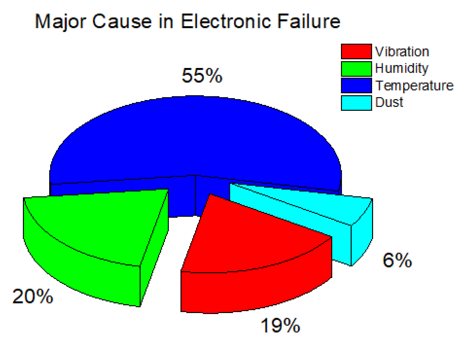
Figure 2.
Heat sinks Topology [9]. Reproduced with permission from Khattak. et al., [9]; published by Electronic materials, 2024.
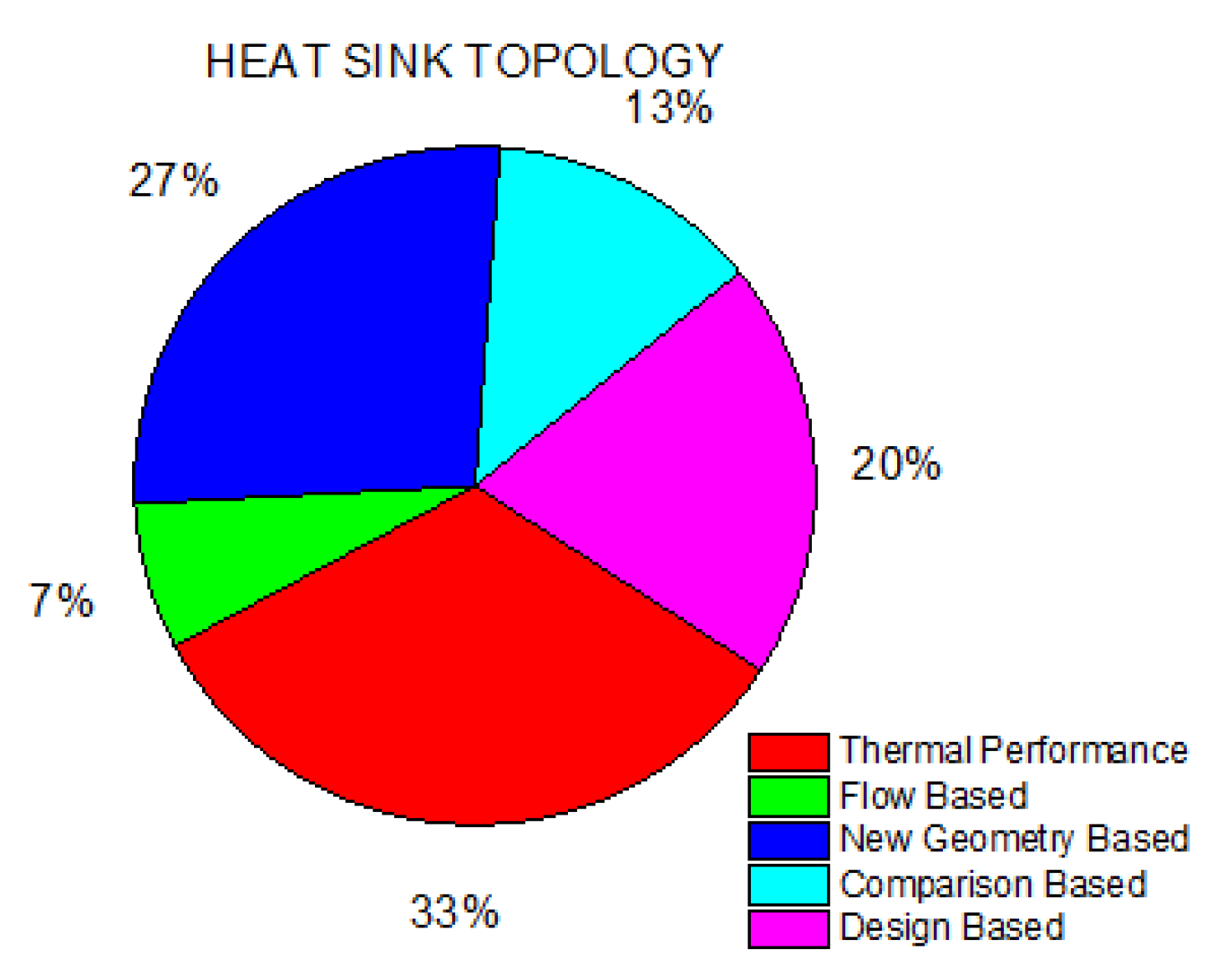
Figure 3.
Number of Studies vs Flow Type [10]. Reproduced with permission from Adham.et al, [10]; published by Electronic materials, 2024.
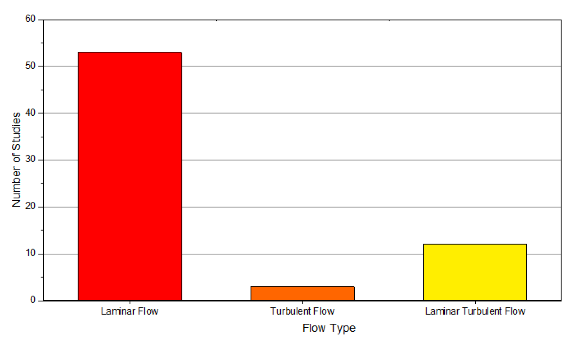
Figure 4.
A typical plate-fin heat sink [13].
Figure 4.
A typical plate-fin heat sink [13].
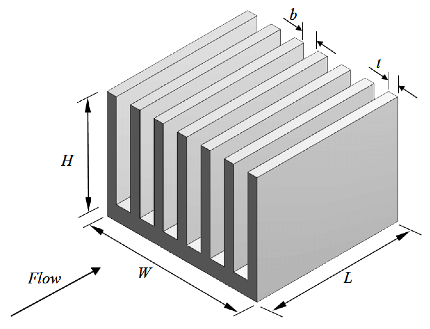
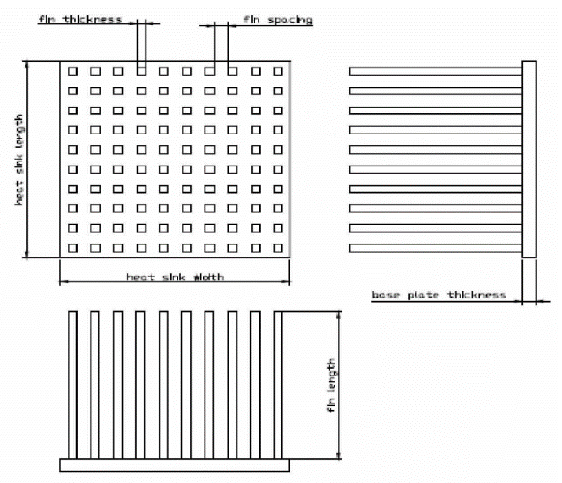
Figure 6.
Heat transfer enhancement techniques for MCHS.
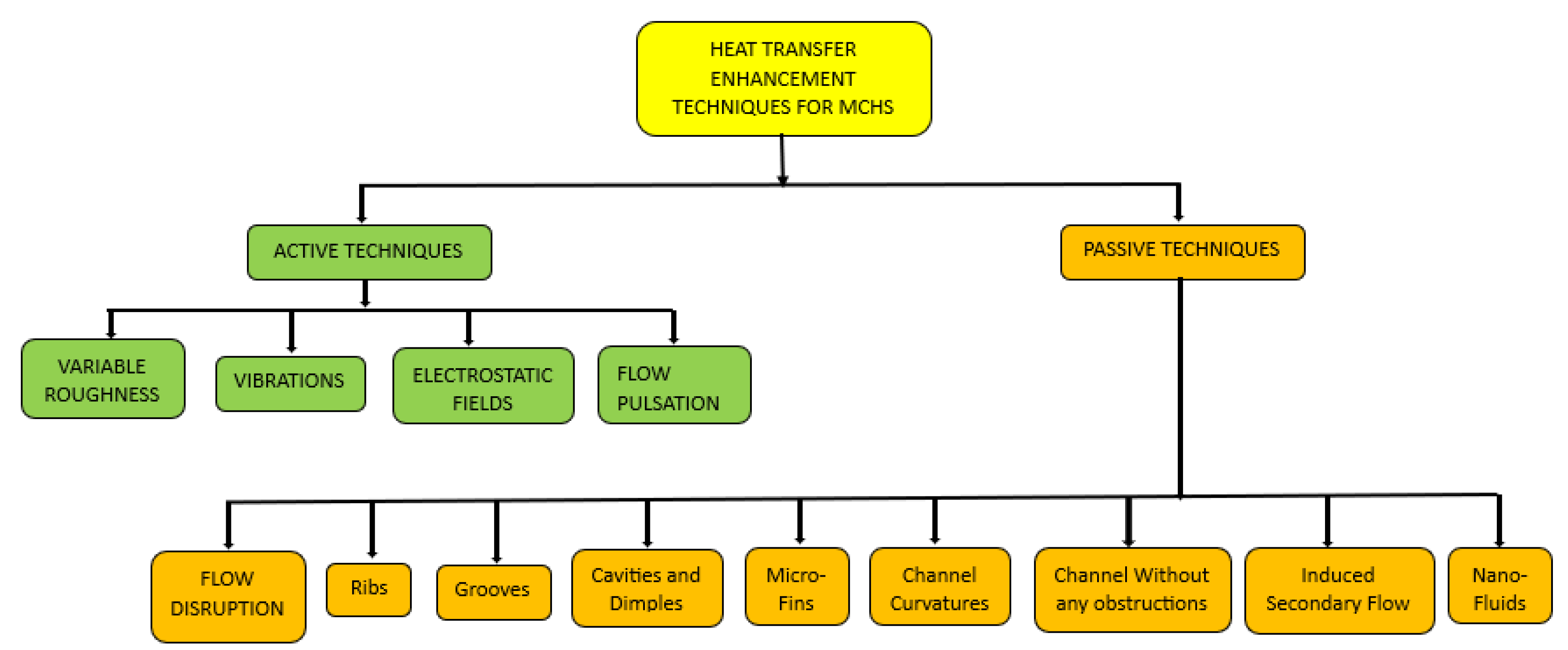

Table 1.
Additional Data for Ribs.
| S.No | Authors | Geometry | Nature of Work | Substrate Material | Coolant Type | Key Findings |
|---|---|---|---|---|---|---|
| 1 | D. B. Tuckerman. et al. [11] | Rectangular | Experimental | Silicon | Water | Maximum thermal resistance of 0.1oC/W for 1cm2 area Thermal resistance depends on water flow rate |
| 2 | Guilian Wang.et al [30] | Rectangular with Microscale Ribs and Grooves | Experimental and Numerical | Silicon | Water | Nusselt number is 1.55 times and friction factor is 4.09 greater than smooth channel |
| 3 | G. D. Xia et al [31] | Rectangular with arc-shaped ribs and grooves | Numerical | Silicon | Water | Relative rib height shows best performance in terms of thermal resistance |
| 4 | Faraz Ahmad.et al [32] | Rectangular with cylindrical ribs and cavities | Numerical | Silicon | Water | Maximum Nu value of 20 at Re 1000 Maximum thermal enhancement factor of 1.02 |
| 5 | Shahzad Ali. et al. [33] | Rectangular with Hydrofoil Ribs | Numerical | Copper | Water | Nu value of 15 at Re 1000 Thermal enhancement factor value of 1.07 |
| 6 | Aatif Ali Khan. et [34] | Rectangular heat sink with different ribs configuration. | Numerical | Silicon | Water | Rectangular ribs show greatest pressure drop of 100kpa Nu value of 8.5 at Re 500 Thermal enhancement factor of 0.91 |
| 7 | Yao Hsien. et al. [35] | Rectangular with ribs and grooves | Experimental | Copper | Water | Heat transfer coefficient increased by 40% (Nu value of 300) Thermal enhancement factor of 2.8 for discrete ribs and grooves |
| 8 | Lau. et al. [36] | Square with Staggered Ribs | Experimental | Copper | Water | Discrete ribs show superior performance than ribbed walls |
| 9 | Shizhong Zhang. et al. [37] |
Rectangular with trefoil-shaped ribs |
Numerical | Copper | Water | Maximum Nu of 30 at Re 1000 Thermal Enhancement factor of 1.5 Maximum entropy augmentation number of 0.72 |
| 10 | Guilian Wang.et al [38] | Rectangular with bidirectional Ribs | Experimental and Numerical | Silicon | Water | Thermal enhancement factor greater than 1 Nu 1.42 times higher with bidirectional ribs (Nu value of 13) |
| 11 | Sadiq Ali. et al. [39] | Rectangular with trefoil-shaped ribs | Numerical | Copper | Water | Maximum pressure drop of 60kpa Maximum Nu value of 29 Thermal Enhancement factor of 1.60 at Re 1000 |
| 12 | M. M. U. Rehman.et al [40] | Rectangular with Side wall Ribs | Numerical | Copper | Water | Maximum thermal enhancement factor of 1.10 Maximum average heat transfer coefficient value of 19 at Re 1000 Highest pressure drop of 19kpa at Re 1000 |
| 13 | Ihsan Ali Ghani.et al [41] | Rectangular with rectangular ribs and sinusoidal cavities | Numerical | Silicon | Water | Performance factor value of 1.83 at Re 800 Average Nu value of 24 at Re 1000 |
| 14 | Lei Chai. et al. [42] | Interrupted with rectangular ribs | Numerical | Silicon | Water | Thermal enhancement factor of 1.3 Interrupted channel without ribs shows high heat transfer |
| 15 | Y.F. Li. et al. [43] | Rectangular with rectangular ribs and triangular cavities | Numerical | Silicon | Water | Thermal enhancement factor of 1.6 at Re 500 Entropy augmentation number of 0.95 Average Nu value of 17 |
| 16 | Y.L. Zhai. et al. [21] | Rectangular with rectangular, trapezoidal, and circular ribs | Numerical | Water | Maximum Nu value of 15 at Re 600 Thermal enhancement factor of 1.6 Field synergy number of 14 Entropy augmentation number of 0.94 |
|
| 17 | Ayodeji S. Binuyo [44] | Interrupted | Numerical | Silicon | Water | Highest Nu value of 14 Average friction factor value of 0.08 |
| 18 | Abdelkader Korichi.et al [45] | Rectangular with heated obstacles | Numerical | Highest Nu value of 23 Increase in friction factor by factor of 19 |
||
| 19 | Aparesh Datta. et al. [46] | Microchannel with Triangular cavities and ribs | Numerical | Silicon | Water | Highest Nu value of 18 Highest friction factor value of 0.80 Performance factor value of 1.45 |
| 20 | Faraz Ahmad. et al. [47] | Rectangular with side wall ribs | Numerical | Copper | Water | Base and side walls ribs show superior performance than all wall |
| 21 | Q.Zhu et al. [48] | Rectangular with rectangular grooves and different-shaped ribs | Numerical | Silicon | Water | Highest pressure drop value of 119kpa Average Nu value of 22 Maximum thermal efficiency of 145% |
Table 2.
Additional Data for Grooves.
| S. No | Author | Nature of work |
Geometry | Coolant type |
Substrate Material | Key Findings |
|---|---|---|---|---|---|---|
| 1 | Pankaj Kumar [50] | Numerical | trapezoidal MCHS with the groove structure | Water | Silicon | Performance factor of 0.62 Friction factor of 0.026 Maximum Pressure drop of 140kpa |
| 2 | Hamdi E. Ahmed.et al [49] | Numerical | Grooved MCHS | Water | Aluminum | Maximum Performance evaluation factor of 2 Average Nusselt number ratio of 1.9 |
| 3 | Guodong Xia.et al [51] | Numerical | MCHS with triangular reentrant cavities | Water | Silicon | Highest thermal enhancement factor of 1.6 Friction factor value of 73 |
| 4 | Cila Herman.et al [52] | Experimental | grooved MCHS with curved vanes |
Air | Copper | Pressure drop increase by 3-5 times than smooth channel Heat transfer increase by 1.5-3.5 times than smooth channel |
Table 3.
Additional Data for Cavities and Dimples.
| S. No | Author | Nature of Work | Geometry | Coolant type | Substrate Material | Key Findings |
|---|---|---|---|---|---|---|
| 1 | Mohib-ur-Rehman.et al [46] | Numerical | MCHS with hemispherical shape protrusions/ dimples |
Water | Copper | Maximum pressure drop value of 50kpa Friction factor value of 3.5 Entropy augmentation number of 0.85 |
| 2 | Minghai Xu. et al. [54] | Numerical | MCHS with dimples | Water | Copper | Highest Nusselt number value of 20 Performance improved by increasing number of dimples |
| 3 | Yu Chen. et al. [55] | Numerical | MCHS with turbulent flow over the dimpled surface | _ | _ | Highest Performance ratio of 2.8 |
| 4 | Moon. et al. [56] | Experimental | Rectangular MCHS with concavities | _ | _ | Normalized Nu value of 2.1 Thermal enhancement factor of 1.75 |
| 5 | Suabsakul Gururatana [57] | Numerical | Rectangular MCHS with dimpled surfaces | Air | _ | Maximum pressure drop of 8Pa at Re 350 Local Nu value of 17 Performance factor of 1.016 |
Table 4.
Additional Data for Microfins.
| S. No | Author | Nature of Work |
Geometry | Coolant type | Substrate Material | Key Findings |
|---|---|---|---|---|---|---|
| 1 | Nawaz Khan. et al. [17] |
Numerical | Rectangular MCHS having pin fins configuration of varying height | Deionized ultra-filtered water | Copper | Highest pressure drop of 7000Pa Nu value of 13 Thermal enhancement factor of 1.4 |
| 2 | Dogan.et al [16] | Experimental | Rectangular MCHS with Longitudinal fins |
Air | Silicon | Maximum convection heat transfer coefficient value of 27 Highest Nu value of 250 |
| 3 | F.Hong.et al [58] |
Numerical | Rectangular MCHS with offset strip-fin | Water | Silicon | Pumping power value of 0.21 W Maximum Presssure drop value of 120kPa |
| Ping Li. et al. [59] | Numerical | Rectangular MCHS with dimple and pin-fin | Water |
- |
Performance factor of 1.9 Highest Nu ratio value of 2.3 |
Table 5.
Additional Data for Channel Curvature.
| S. No | Author | Nature of Work |
Geometry | Coolant type |
Substrate Material | Key Findings |
|---|---|---|---|---|---|---|
| 1 | Chu.et al61] | Experimental | Triangular MCHS | Water | Silicon | Friction factor value of 21 Highest Nu value of 0.7 |
| 2 | Daxiang Deng. et al. [62] | Numerical and Experimental | MCHS with semi-closed omega-shaped configuration. | Deionized Water | Oxygen-free Pure copper | Pressure drop of 8kpa Maximum thermal resistance value of 0.41oC/W |
| 3 | Ping cheng.et al [63] | Experimental | trapezoidal MCHS | Water | Silicon | Nu value of 4 at Re 700 Apparent friction factor value of 32 |
| 4 | H.A. Mohammed. et al. [64] | Numerical | Rectangular MCHS with various wavy amplitudes | Water | Aluminum | Maximum friction factor value of 0.55 Pressure drop value of 6.2kPa |
| 5 | Gunnasegran.et al [65] | Numerical | zigzag, curvy, and step microchannel heat sinks | Water | Aluminum | Heat transfer coefficient value of 9.64 Maximum pressure drop of 2800Pa Poiseuille number value of 25 |
| 6 | H. Ghaedamini.et al [66] | Numerical | converging-diverging MCHS | Water | Silicon | Highest Nu value of 30 Performance factor of 1.18 |
| 7 | X. F. Peng.et al [67] | Experimental | Squared Shape MCHS | Water | Silicon | Highest Nu value of 4.61 Heat transfer coefficient value of 30500W/m2 |
| 8 | Xiang-Qi Wang.et al [68] | Numerical | Rectangular (tree shape ) MCHS |
Water | Silicon | Pressure drop value of 320Pa Studied temperature distribution |
| 9 | John P. Mchale.et al [69] | Numerical | Trapezoidal and square shape MCHS | Water, ethylene glycol, air, and mercury | Silicon and polycarbonate aluminum | Local Nu value of 70 Average Nu value of 90 |
Table 6.
Additional Data for Optimization.
| S.No | Authors | Geometry | Nature of Work | Substrate Material | Coolant Type | Key Findings |
|---|---|---|---|---|---|---|
| 1 | Wang. X.Q. et al. [68] | Pin fins | numerical | copper | Air | Pressure drop value of 330Pa |
| 2 | Mchale. et al. [69] | Pin fins | numerical | aluminum | air | Friction factor value of 24 Nu value of 70 |
| 3 | Harley, J.C. et al. [70] | Plate fin heat sink | numerical | Aluminum alloy | air | Khudsen number less than 0.38 |
| 4 | Ping. et al. [59] | MCHS with dimple and pin fin | numerical | air | Performance factor of 1.9 Highest Nu ratio of 2.4 Maximum friction factor ratio of 1.9 |
|
| 5 | Tiseli.I .et al [71] | Plate fin heat sink | Analytical | copper | Ambient air | Nu value of 5.1 Average temperature of 330K |
| 6 | Harms. et al. [72] | MCHS variable pin fin configuration | Numerical | copper | water | Nu value of 110 Pressure drop value of 60kPa |
| 7 | Toh, K.C. et al. [73] | Rectangular Micro channel | Numerical | Silicon | Water | Thermal resistance value of 0.30 cm2. K/W Friction factor value of 150 |
| 8 | Gamrat, G,. et al. [74] | Rectangular Microchannel | Numerical | Silicon | Water | Nu value of 30 Poiseuille number value of 40 |
| 9 | Xu, J. L. et al. [75] | Rectangular MCHS | numerical | Copper, aluminum, silicon | Water | Nu value of 16 Friction factor value of 0.02 |
| 10 | Peng, X. et al. [76] | Rectangular MCHS | Numerical | Silicon | water | Nu value of 10 Heat transfer coefficient value of 7000W/m2. K |
| 11 | Betz, A.R. et al. [77] | Rectangular MCHS | Numerical | Silicon | Water | Nu value of 14 Pressure drop of 38kPa |
| 12 | Toh, K.C. et al. [73] | Rectangular MCHS | Numerical | Silicon | Air | Friction factor value of 70 Thermal resistance of 0.28cm2/K/W |
| 13 | Zade, A.Q al [78] | Rectangular MCHSs | Numerical | Copper | Water-Air | Nu value of 33 Friction factor value of 70 |
Table 7.
Additional Data for Channel without obstructions.
| S.No | Authors | Geometry | Nature of Work | Substrate Material | Coolant Type | Results Obtained |
|---|---|---|---|---|---|---|
| 1 | Weilin Qu. et al. [19] | Rectangular Microchannel | Experimental and Numerical | Silicon | Water | Average Nu value of 30 Average temperature of 120oC |
| 2 | Deng, B. et al. [79] | Rectangular Microchannel | Experimental | Silicon | Water | Thermal resistance value of 0.19K/W |
| 3 | Saenen. T. et al. [80] | Triangular Microchannel | Experimental and Numerical | Silicon | Water | Average temperature of 128oC |
| 4 | Sharma, C.S. et al. [84] | Rectangular Microchannel | Experimental | Silicon | Water | Pressure drop of 1600Pa Fluid outlet temperature of 65oC Thermal resistance of 0.285oCcm2/W |
| 5 | Japar, W.M.A.A. Al [87] | Rectangular Microchannel | Experimental | Silicon | Water | Nu value of 10 Pressure drop value of 70kPa Nu ratio of 2.3 |
| 6 | Chai, L et al. [88] | Rectangular Microchannel | Experimental | Silicon | Water | Pressure Drop of 60kPa Friction factor value of 60 Nu value of 15 |
| 7 | Chen,C.W.et al [86] | Rectangular Microchannel | Numerical and Experimental | Bronze Block | Water | Thermal resistance of 0.4o C/W/cm2 Large flow power can develop low thermal resistance MCHS |
| 8 | Memon, S.A.et al [89] | Rectangular Microchannel | Experimental | Aluminium | Water | Pressure drop of 2.8Pa Minimum Average temperature of 311K |
| 9 | Yang, M [90] | Rectangular Microchannel | Numerical | - | - | Pumping power of 2.1W Thermal resistance of 1.3K/W |
| 10 | Gao, W.. et al. [91] | Rectangular Microchannel | Numerical | - | - | Pressure drop of 32000Pa Pumping power of 0.01W Nu value of 22 |
| 11 | Kuppusammy,N.R.. et al. [92] | Array Minichannel | Experimental and Numerical | Copper | Water | Nu value of 12.5 with pressure drop of 20kPa |
| 12 | Bahiraei. et al. [93] | Microchannel Heat Sink | Numerical | Silicon | Water | 17% improvement in convective heat transfer coefficient |
| 13 | Min Yang. Et al [83] | Microchannel heat sink with manifold and oblique channels | Experimental | Copper | Water |
Pressure drop of 4.2kPa Friction factor value of 17 |
Table 8.
Additional Data for Other Techniques.
| S. No | Author | Geometry | Nature of work | Substrate Material | Coolant type | Key Findings |
|---|---|---|---|---|---|---|
| 1 | Saenen, T. et al. [80] | Rectangular MCHS | Numerical | Silicon | Air | Maximum temperature of 126oC |
| 2 | Wang S.l. et al. [94] | Rectangular MCHS with turbulent flow | Numerical | Copper | Hot Water | Studied Dean vortex Secondary branches weaken dean vortex |
| 3 | Ali Kosar [14] | Rectangular MCHS |
Numerical | Polyimide, Silica Glass, Quartz, Steel, Silicon, Copper | Water | Nu value of 4 Friction factor of 0.7 |
| 4 | Tsung-Hsun Tsai.et al [117] | Rectangular MCHS with Porous medium | Numerical | Silicon | Cu–water CNT–water | Pressure drop of 350kPa Thermal resistance of 0.073oC/W |
| 5 | Zhigang. et al. [85] | Rectangular microchannels | Numerical | Copper silicon stainless steel | Water | Local friction coefficient of 1 Heat transfer coefficient of 200kW/m2.K Nu vlaue of 25 |
| 6 | Chien-Hsin Chen [18] | Rectangular MCHS |
Numerically | Nu value of 280 Dimensionless velocity of 0.6 |
||
| 7 | Chih-Wei Chen. et al. [86] | Rectangular MCHS |
Silicon | Water | Thermal resistance of 0.4oC/W/cm2 |
Table 9.
Additional Data for Secondary Flow.
| S.No | Author | Geometry | Nature of work | Substrate Material | Coolant type | Key Findings |
|---|---|---|---|---|---|---|
| 1 | Wan Mohd. et al. [8] | Rectangular MCHS | numerical | copper | water | Review of literature |
| 2 | Lei chai. et al. [51] | Rectangular MCHS with triangular cavities | Experimental and numerical | silicon | water | Thermal enhancement factor of 1.6 Nu ratio f 1.8 |
| 3 | Ghani. et al. [101] | Rectangular MCHS with ribs and cavities | numerical | copper | water | Friction factor ratio of 4 Nu ratio of 2.2 Performance factor of 1.7 |
| 4 | Bahirae. et al. [93] | MCHS with ribs and secondary channels | numerical | Copper | Graphene–silver Nano particles | Secondary channel increases area thus reducing pressure drop |
| 5 | Shou lin wang. et al. [94] | Secondary flow branched design | numerical | Silicon | Water | Nu value of 18 Performance factor of 2.3 Thermal resistance value of 1.2 |
| 6 | GD Xia. et al. [95] | Sinusoidal secondary flow MCHS | Experimental | Silicon | Water | Heat trasfer coefficient value of 45 Pressure drop value of 240kPa |
| 7 | SA Razali. et al. [96] | MCHS design with trapezoidal cavities, ribs, and secondary channels | Numerical | Copper | Water | Performance factor of 1.8 Maximum Nu ratio of 2.3 Highest Friction facto ratio of 5.7 |
| 8 | Farzaneh. et al. [97] | Square-shaped MCHS with one and two initial loops. | Experimental | Silicon | Water | Pressure drop reduced by 25% |
| 9 | Huang. et al. [98] | Rectangular Parallel-Slot MCHS | Numerical | Copper | Water | Nu value of 21 Pressure drop ratio of 2000 Performance factor value of 1.95 |
| 10 | Poh Seng Lee. et al. [99] | Secondary flow MCHS with oblique fins | Experimental | Copper | Water | Average Nu value of 16 Thermal resistance value of 0.097OC/W Pressure drop value of 3000Pa |
| 11 | Yan Fan. et al. [100] | novel cylindrical discrete oblique fin MCHS with secondary flow | Numerical | Copper | Water | Pressure drop of 90Pa Heat transfer coefficient value of 3000W/m2. K |
Table 10.
Additional Data for Nanofluids.
| S. No |
Author | Geometry | Nature of work | Substrate Material | Coolant type | Results Obtained |
|---|---|---|---|---|---|---|
| 1 | S.abubakar. et al. [103] | Straight Rectangular MCHS | numerical | silicon | Pure water, Fe3O4- H2O4 | Maximum average temperature of 316K |
| 2 | A.Sivakumar. et al. [104] | serpentine-shaped MCHS | Experimental and numerical | copper | Ethylene glycol-based CuO, water-based CuO, and Al2O3 | Heat transfer coefficient value of 42kW/m2. K Pressure Drop of 0.30kPa |
| 3 | L.snoussi. et al. [105] | Rectangular Cross section 3D MCHS | numerical | copper | Al2O3-water, Cu–water | Heat transfer coefficient value of 16kW/m2.K Friction factor value of 0.07 |
| 4 | Sarafraz. et al. [106] | Rectangular MCHS | experimental | copper | Multi-walled carbon nanotubes | Heat transfer coefficient value of 7000W/m2.K Thermal resistance value of 0.11W/o C |
| 5 | Thansekhar. et al. [107] | Rectangular MCHS | experimental | copper | Al2O3/water,SiO2/water | Heat transfer coefficient value of 180W/m2.K Thermal resistance value of 1.1K/W Pressure drop value of 0.035bar |
| 6 | A.A.A Arani. et al. [108] | Truncated double-layer MCHS | numerical | silicon | water/single-wall carbon nanotubes (SWCNT) | Maximum Pressure drop value of 500kPa Highest Friction factor value of 0.21 Average Nu value of 3 |
| 7 | Arabpour, A.et al [109] | Zigzag flow channels |
experimental | copper | SiO2/ DI water | Nu value of 14 Enhancement ratio of 1.2 Maximum Pressure drop value of 110kPa |
| 8 | R.Vinoth. et al. [7] | Oblique finned MCHS with square, semicircle, and trapezoidal cross-sections | experimental | copper | Al2O3/water | Nu value of 19 Pressure drop of 20kPa Friction factor of 3.8 |
| 9 | Abollahi.et al [110] | Interrupted MCHS with ellipse and diamond ribs. |
numerical | copper | Al2O3/water | Highest Nu value of 13 Maximum Friction factor value of 0.34 Highest performance factor of 1.3 |
| 10 | Altayyeb Alfaryajat.et al [111] | 3D rhombus MCHS | numerical |
- |
Al2O3 mixed with different four base fluids pure water engine oil glycerin ethylene glycol |
Heat transfer coefficient value of 27kW/m2. K Highest friction factor value of 0.040 |
| 11 | MM Sarafraz. et al. [112] | Straight rectangular MCHS | experimental | copper | Biologically produced silver-water | Highest heat transfer coefficient value of 7000W/m2.K Thermal resistance value of 0.11W/o C Maximum Pressure drop of 55kPA |
| 12 | Nagoctan Tran. et al. [113] | Multi nozzle trapezoidal MCHS | numerical | copper | Al2O3and TiO2 | Thermal resistance value of 0.35OC/W Highest Pressure drop of 55kPa |
| 13 | Zongjie Lyu. et al. [104] | Single-layer fractal MCHS |
numerical | silicon | water and kerosene | Highest Nu value of 45 Pumping power value of 0.15W Maximum performance factor of 2.3 |
| 14 | A.A Razali. et al. [114] | Rectangular MCHS | Experimental and numerical | copper | Al2O3 | Nu value of 6 |
| 15 | AR Chabi. et al. [115] | Rectangular MCHS | experimental | copper | CuO/water | Heat transfer coefficient value of 20000W/m2. K Average Nu value of 13 |
| 16 | Manay. et al. [116] | Rectangular MCHS | experimental | copper | TiO2–water | Nu value of 12 Thermal resistance value of 0.8OC/W |
Disclaimer/Publisher’s Note: The statements, opinions and data contained in all publications are solely those of the individual author(s) and contributor(s) and not of MDPI and/or the editor(s). MDPI and/or the editor(s) disclaim responsibility for any injury to people or property resulting from any ideas, methods, instructions or products referred to in the content. |
© 2024 by the authors. Licensee MDPI, Basel, Switzerland. This article is an open access article distributed under the terms and conditions of the Creative Commons Attribution (CC BY) license (https://creativecommons.org/licenses/by/4.0/).
Copyright: This open access article is published under a Creative Commons CC BY 4.0 license, which permit the free download, distribution, and reuse, provided that the author and preprint are cited in any reuse.


