Submitted:
21 August 2024
Posted:
23 August 2024
You are already at the latest version
Abstract
The world is currently facing an energy crisis. To solve the problem, many countries have been exploring renewable energy sources. However, the existing renewable energy sources are highly dependent on weather changes, necessitating the utilization of significantly expensive and large storage batteries.As a solution, we propose a system for generating renewable energy. The proposed system comprises a current source and a voltage source connected in series. With appropriate adjustments, the current source supplies current without voltage and the voltage source provides voltage without current. Considering that electric power is a product of current and voltage, electric power is generated from the interaction between the current source and voltage source. In our previous study, the same result was obtained; however, the output voltage was low, which resulted in a low amount of generated energy. In this study, by introducing some ingenuities, we successfully increased the output voltage. Consequently, we succeeded in powering a light-emitting diode and charging a super-condenser to the standard voltage. Using this system, we generated a relatively large amount of energy in the right place and at the right time, validating our systems’ robustness to changes in weather. The large-scale adoption of our system could contribute to solving the global energy crisis.
Keywords:
current source
; voltage source
; electric power
; renewable energy
; circuit
; light-emitting diode
; super-condenser
1. Introduction
The world is facing an energy crisis owing to the limited availability of crude oil and natural gas, requiring swift resolutions. Thus, it is imperative to introduce renewable and sustainable energy sources [1,2,3,4,5]. Among such sources, solar and wind are renowned [6]. Notably, the limited availability of crude oil and its high cost have resulted in economic problems. Furthermore, its continuous use has increased the CO2 concentration in the atmosphere [7,8]. For the promotion of renewable energy sources, considering both economic and technological views is necessary. Specifically, achieving high-efficiency energy generation at a low cost is imperative [9,10].
To reduce the atmospheric CO2 concentration and promote environmental sustainability, a significant increase in the adoption of existing renewable energy sources, such as solar or wind power, is imperative. Unfortunately, the integration of these renewable energy sources into existing power systems results in frequency and voltage disruptions. Moreover, to maximize the effectiveness of these existing energy sources, expensive storage batteries are required.
Japan has a goal of achieving net-zero carbon neutrality by 2050. However, according to simulations [11,12], it might be impossible to achieve this goal without some breakthroughs.
Below, we have summarized the main challenges of the existing renewable energy and nuclear power generation systems.
- (1)
- The renewable energy sources are vulnerable to weather changes. This disadvantage necessitates the use of large and expensive storage batteries. Furthermore, the integration of renewable energy sources into existing energy generation systems results in unstable outputs.
- (2)
- The potential to achieve the goal has been calculated using simulations; however, nuclear power generation was included. Moreover, the Fukushima nuclear accident in Japan in 2011 was not considered.
Therefore, we propose a system for providing a stable energy supply that satisfies the demands of Japan, i.e., the right amount of energy in the right place and at the right time.
In our system, a voltage source, a current source, and normal diodes are connected in series. With appropriate adjustments, the current source supplies current without voltage and the voltage source provides voltage without current. As is known, electric power is a product of voltage and current. The voltage and current outputs interact, generating electric power. The net inputs to both the current source and the voltage source are zero, whereas the net output is greater than zero, as evidenced by the interaction between the two sources. In this study, we evaluate the proposed system using experiments. Previously, we published an article that conveys the same results [13]. However, in that study, the output voltage was very low, resulting in a low amount of generated electrical power. However, in this study, the following ingenuities were introduced:
- 3)
- Normal diodes were introduced to increase the output voltage.
- 4)
- By opening the circuit partially, a load is inserted.
Accordingly, we succeeded in outputting a relatively high voltage, which in turn enabled the generation of relatively high electric power. The structure of this paper is presented below.
Before considering the main system, the working principles of the voltage and current sources, which are parts of our proposed system, are reviewed. Subsequently, the principle (i.e., the methodology) of our system is described. Afterward, a more concrete method for the experiments is presented. Thereafter, the results of the experiments, in which a light-emitting diode (LED) is employed as a load and a super-condenser is charged, are discussed. Furthermore, the limitations and significance of this study are presented. Finally, the paper is concluded.
2. Review of the Voltage and Current Sources
In this study, voltage and current sources, which are components of an electric circuit, are employed. Note that the voltage source outputs voltage regardless of the load, whereas the current source supplies current regardless of the load. The symbols in an electric circuit are illustrated in Figure 1. We employ two stabilized power sources: one as the constant voltage (CV) source and the other as the constant current (CC) source.
3. Method
Our system is illustrated in and 2-2. Therein, Panel (A) depicts a specific state of the circuit (SS circuit) in which energy is generated. Panel (B) depicts the circuit featuring an LED or a super-condenser. In Panel (A), i.e., the SS circuit, there is a current source (i.e., in CC mode), a voltage source (i.e., in CV mode), and series normal diodes (excluding the LED). Subsequently, we consider the process in Panel (A).
- (1)
- First, in the CV mode of the stabilized power supply, a voltage V0 is set.
- (2)
- The current source of the above-stabilized power supply is reset to the CC source. Therefore, V0 becomes the upper-limit voltage, not the net charged voltage between the taps of this power supply. V0 refers to the voltage up to which the current source works. However, after setting the voltage and resetting the power supply to the CC source, the voltage tap does not appear and reads zero. At the output voltage of 0.0 V, the CC mode changes to the CV mode. This implies that the CC mode immediately changes to the CV mode without the main current supply.
- (3)
- The CV source (the other stabilized power supply) is set to a value at which the current does not flow.
- (4)
- The CC source outputs a net current of J [A].
- (5)
- When the above 4) is implemented, voltage Vβ [V] appears between the taps of the CC source. However, by introducing voltage V2 [V], which is higher than the initial voltage from the voltage source, the voltage, Vβ, is reduced to zero. Moreover, as reported in the Results section, even when the output voltage of the CV source further increases, the current along the circuit persists. This implies that the current along the circuit originates from only the current source, not the voltage source.
- (6)
- Considering that electric power is the product of voltage and current, according to the above procedure, although the input power to both the voltage and current sources is zero, an interaction between the outputs of these sources generates electric power ([W]). This electric energy powers an LED or super-condenser. We refer to this modified circuit as the SS circuit.
- (7)
- Next, a blue LED or a super-condenser is installed in the SS circuit for confirmation.
- (8)
- After the confirmation, either the voltage source or the current source is turned off to validate the generation of electric power ([W]).
- (9)
- In the above state for the LED, the energy relation is expressed as follows:where the second term of the left-hand side implies the required electric power of the LED. If this condition is satisfied, the LED will work. In the Results section, we present experimental photos of the LED working. As demonstrated in these photos, the current along the circuit will become approximately zero, despite the functioning of the LED. This is because the “=” option of Equation (1), i.e., the minimum point, applies.
Figure 2-1.
The procedure used to power an LED. The left panel implies an energy-generating circuit (the SS circuit), in which the current source provides current without voltage and the voltage source provides voltage without current. That is, electrical power is generated by this circuit. In the right panel, an LED is inserted for confirmation.
Subsequently, instead of the blue LED, we consider the energy storage of a super-condenser. Note that except for the insertion of the condenser, the settings of the two power supplies are the same, as shown in Panel (A) (i.e., the SS circuit).
We consider the following:
- (1)
- The initial time impedance of the condenser is zero.
- (2)
- According to energy conservation, the generated electric power from the SS circuit (JV2 [W]) results in the storage of energy by the super-condenser.
Therefore, the following equation holds:
where Cs, J, and vc denote the capacitance of the super-condenser, current of the current source, and final charged voltage of the super-condenser, respectively.
In this equation, time dt is derived as follows:
That is,
where V0 implies the initial output voltage from the current source to the SS circuit.
The above equation is substituted:
That is,
In the above equation, the following assumption is made:
Considering this, the charged voltage of the super-condenser becomes
In Table 1, the experimental and theoretical results (i.e., Equation (9)) are compared and shown to be consistent. This consistency implies that the initial assumption in Equation (2) is correct. Note that in our power supply system, if V0 is less than 1.0, no current is supplied.
Notably, in both the cases of the LED and the super-condenser, if either the voltage source or the current source is turned off, the LED stops working or the charging process of the super-condenser immediately stops. This indicates that the interaction between the voltage and current sources generates electric power.
Figure 2-2.
The left panel indicates the circuit that generates electrical power (the SS circuit). The right panel indicates the insertion of a super-condenser to verify the energy generation in the left panel.
Figure 2-2.
The left panel indicates the circuit that generates electrical power (the SS circuit). The right panel indicates the insertion of a super-condenser to verify the energy generation in the left panel.
Let us Next, we consider the reason why the series diodes (excluding the LED) are needed. Without a diode along the circuit, a very low output voltage (V2) is obtained, resulting in a flow of current from the voltage source. Thus, with the series diodes, a high voltage (V2) is obtained, preventing current flow in the voltage source. Considering that the forward bias voltage of a diode is typically ~0.8 V, a five-series-diode setup, for example, would provide a voltage of V, at which point no current would flow through the voltage source.
4. Results
In –3-9, the working process of the blue LED is depicted. There are 10 procedures; for details, see each caption. Note that Figure 3, Figure 4, Figure 5, Figure 6, Figure 7 and Figure 8, 3-9-a and 3-9-b is s set with each other, which demonstrates the interaction between the voltage and current sources to generate electric power.
Figure 3-1.
The view of the entire circuit (A). Note that the left power supply works as the CC source, whereas the right one operates as the CV source.
Figure 3-1.
The view of the entire circuit (A). Note that the left power supply works as the CC source, whereas the right one operates as the CV source.
Figure 3-2.
First, voltage V0 is set. The next photo indicates the change in the power source to the CC source.
Figure 3-2.
First, voltage V0 is set. The next photo indicates the change in the power source to the CC source.
Figure 3-3.
After V0 is set, the power source is changed to the CC source.
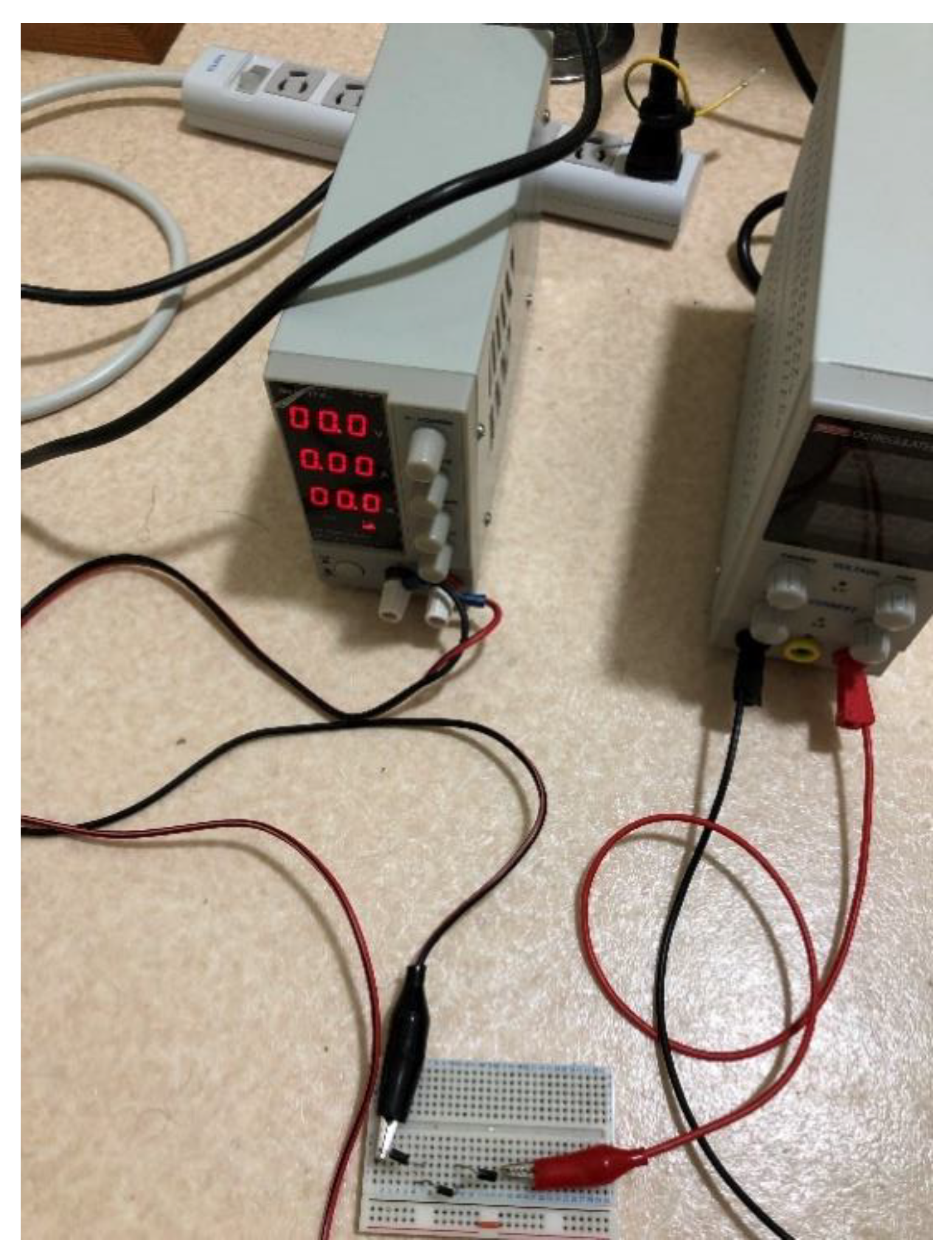
Figure 3-4.
Output voltage from the voltage source in CV mode. Note that up to this voltage, no current flows because of the impedance of the three normal diodes.
Figure 3-4.
Output voltage from the voltage source in CV mode. Note that up to this voltage, no current flows because of the impedance of the three normal diodes.
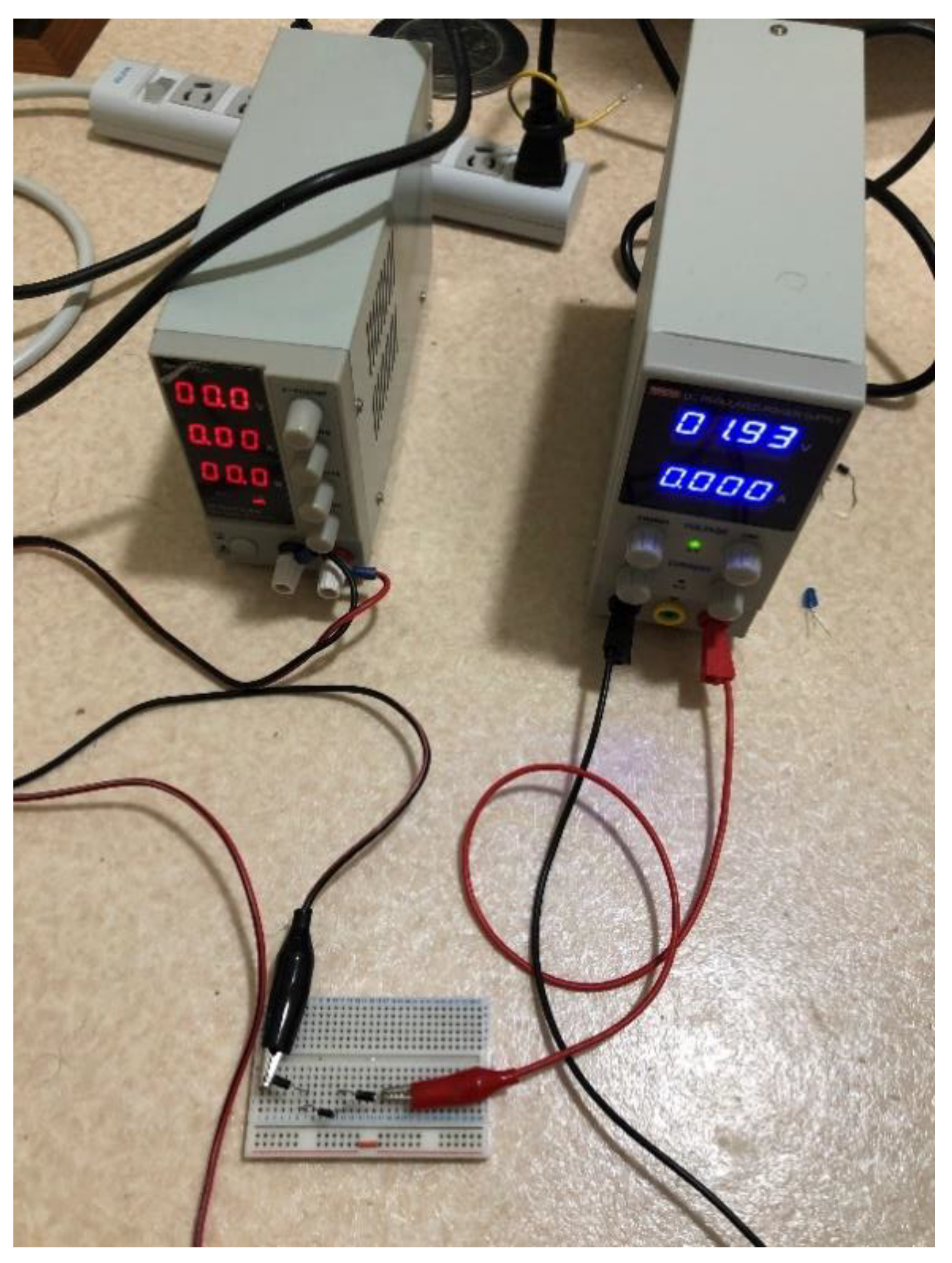
Figure 3-5.
A current of ~70 mA is input from the current source.. Moreover, since the performance of the left power supply is inferior to that of the right power supply, their current values strictly do not correspond.
Figure 3-5.
A current of ~70 mA is input from the current source.. Moreover, since the performance of the left power supply is inferior to that of the right power supply, their current values strictly do not correspond.
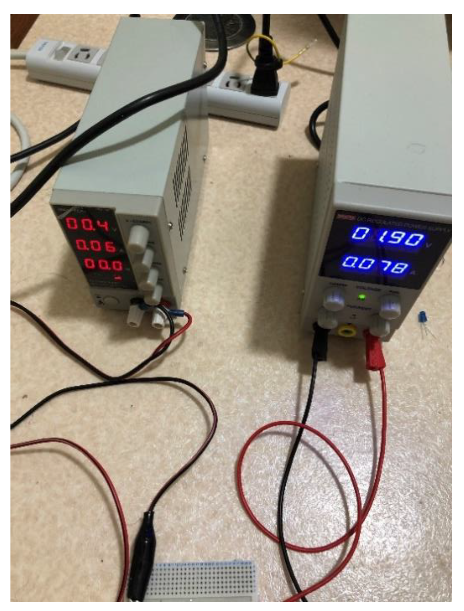
Figure 3-6.
From the previous photo, voltage V2, outputted from the voltage source, is input. Accordingly, the voltage (0.4 V) from the current source decreases to 0.0 V. However, the current (J) along the circuit (i.e., approximately 70 mA) persists, implying that the furthest voltage input does not result in an input of current from the voltage source. Consequently, electric power (i.e., energy) is generated as described previously. We define this state as the SS.
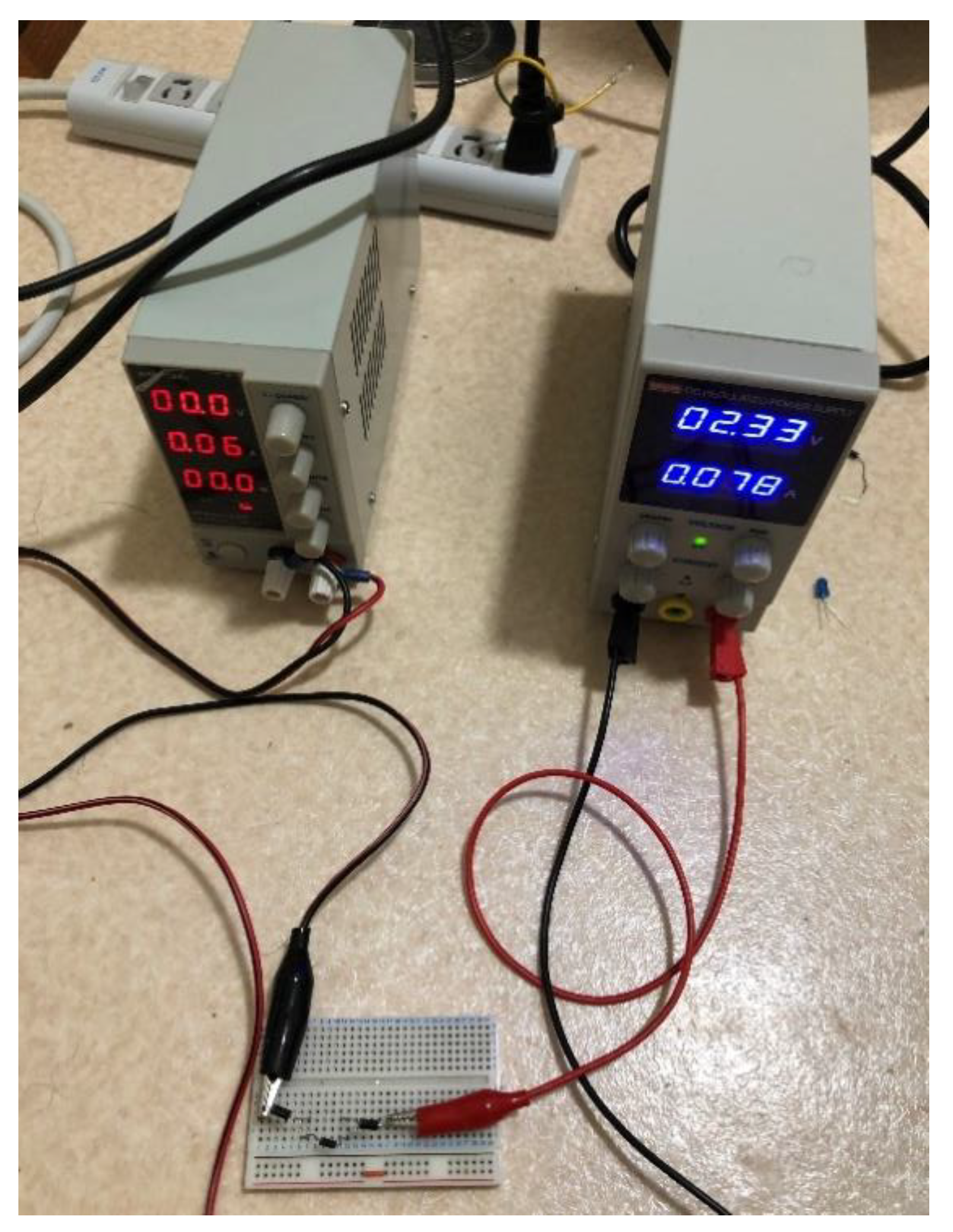
Figure 3-7.
A part of the circuit is opened to insert the blue LED.
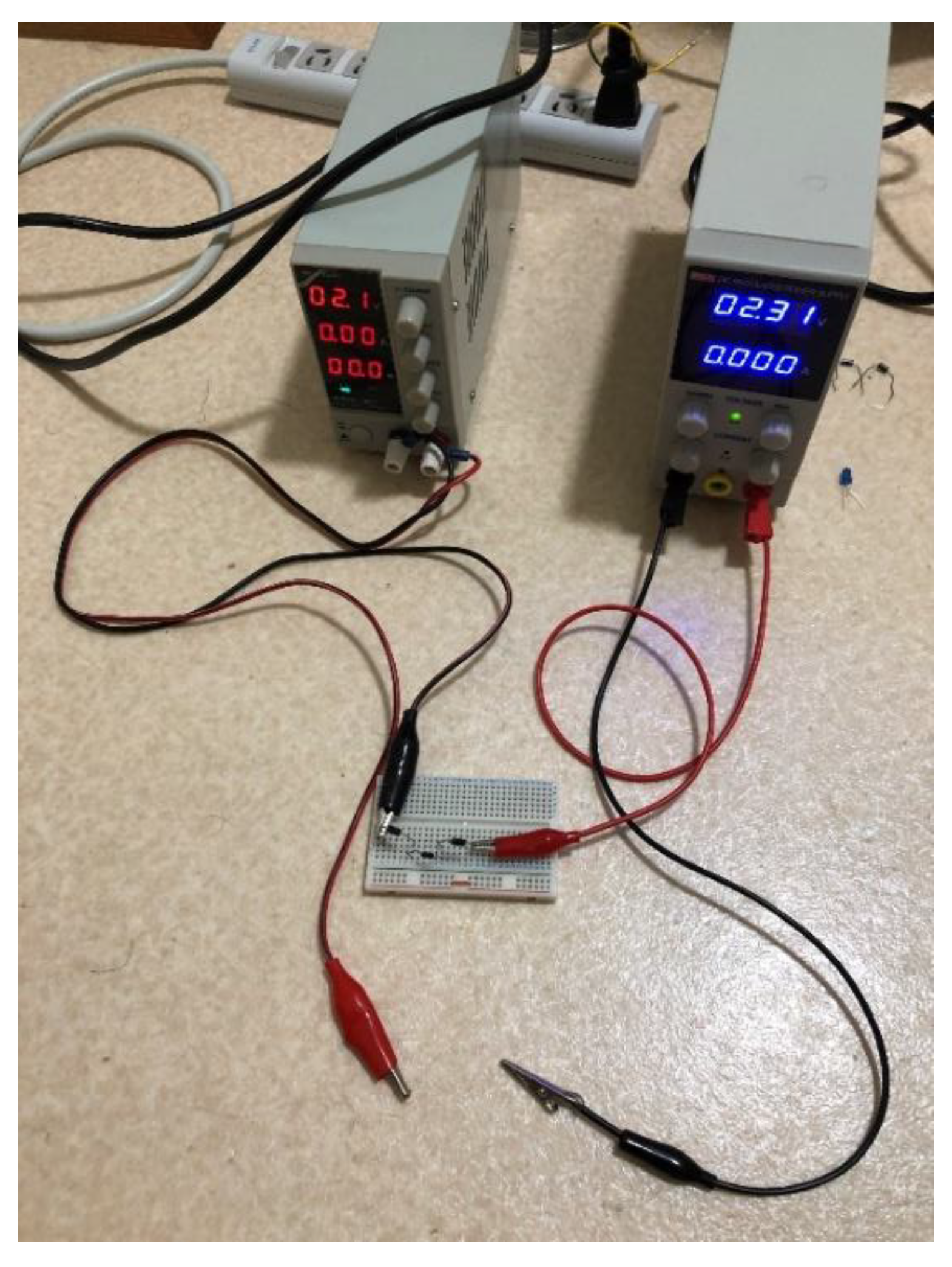
Figure 3-8.
The result of inserting the LED. It works despite the approximately zero current (0 mA) across the circuit. This implies that the generated energy was transmitted to the LED by the method expressed in Equation (1).
Figure 3-8.
The result of inserting the LED. It works despite the approximately zero current (0 mA) across the circuit. This implies that the generated energy was transmitted to the LED by the method expressed in Equation (1).
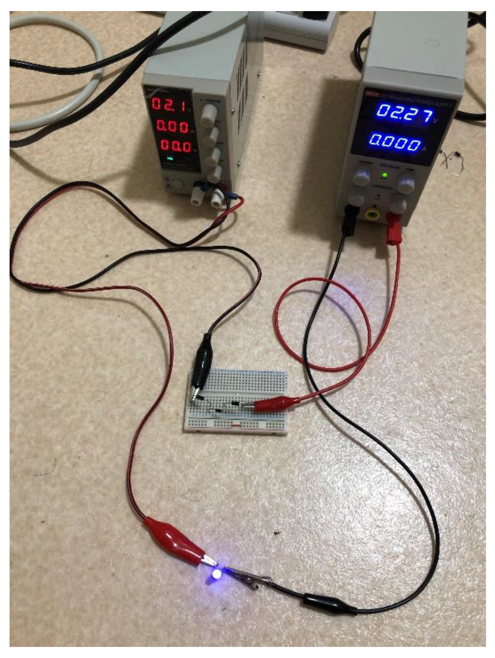
Figure 3-9a.
After the LED is powered, the current source turns off and the LED also goes off.
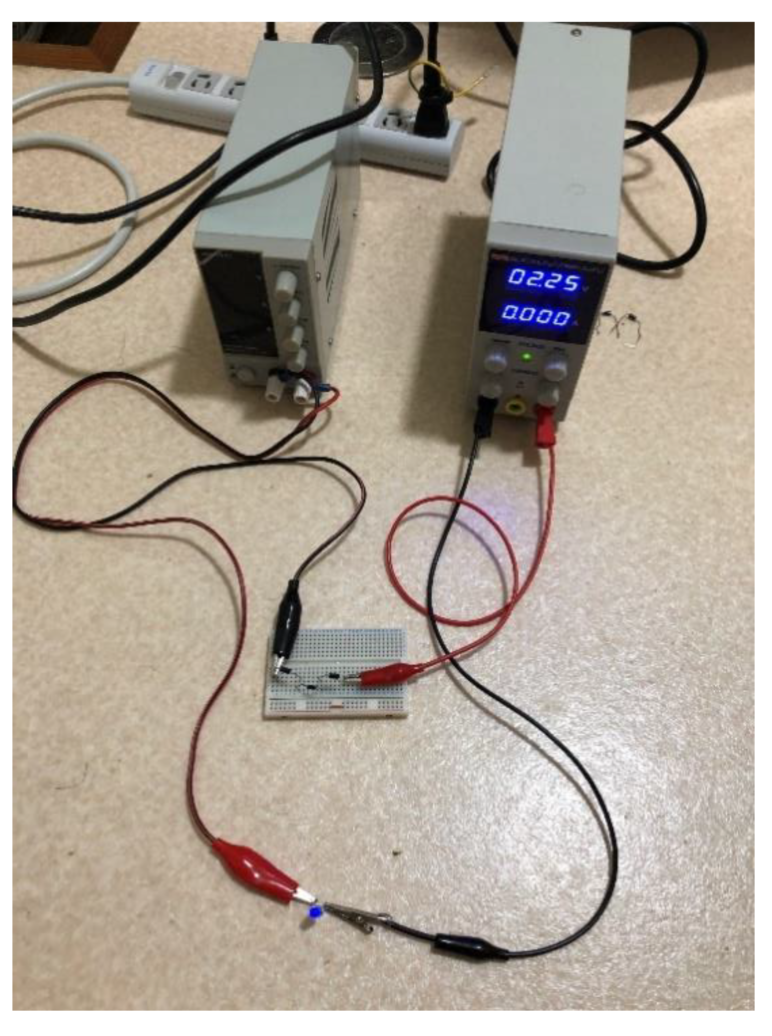
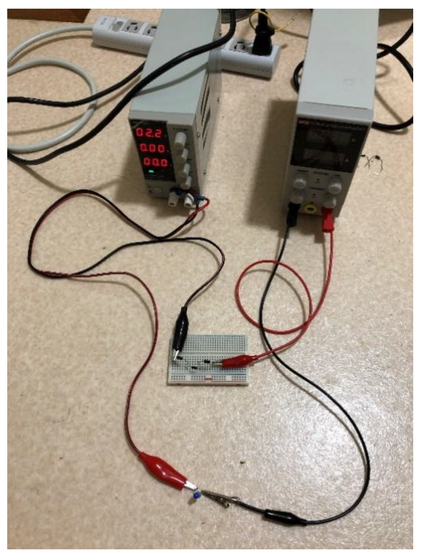
Figure 3-9-b.
After the LED is powered, the voltage source turns off, and the LED also goes off. From the previous photo, we realize that the interaction between the current source and the voltage source resulted in the generation of electric power (i.e., new energy).
Figure 3-9-b.
After the LED is powered, the voltage source turns off, and the LED also goes off. From the previous photo, we realize that the interaction between the current source and the voltage source resulted in the generation of electric power (i.e., new energy).
Subsequently, in to 5-6, the process of charging a super-condenser is depicted. Note that in this case, we start from the SS circuit. In Figure 4, our employed super-condenser is depicted.
Figure 4.
The employed super-condenser. The capacitance is 3.3 F, and the standard voltage is 2.5 V.
Figure 4.
The employed super-condenser. The capacitance is 3.3 F, and the standard voltage is 2.5 V.
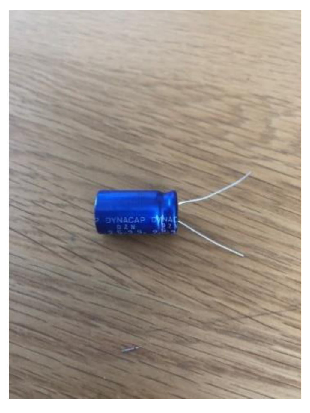
Figure 5-1.
The view of the whole experiment. We start from the SS circuit. In addition to the previous device, we can observe the blue super-condenser, which is now shorted, along with its voltmeter. Note that there are five normal diodes. Moreover, the current from the current source is approximately 0.16 A, and the voltage from the voltage source is approximately 4.1 V..
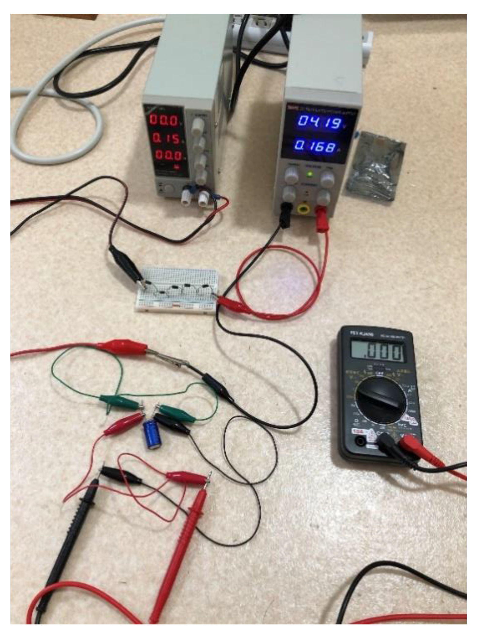
Figure 5-2.
A part of the circuit is opened to insert the super-condenser..
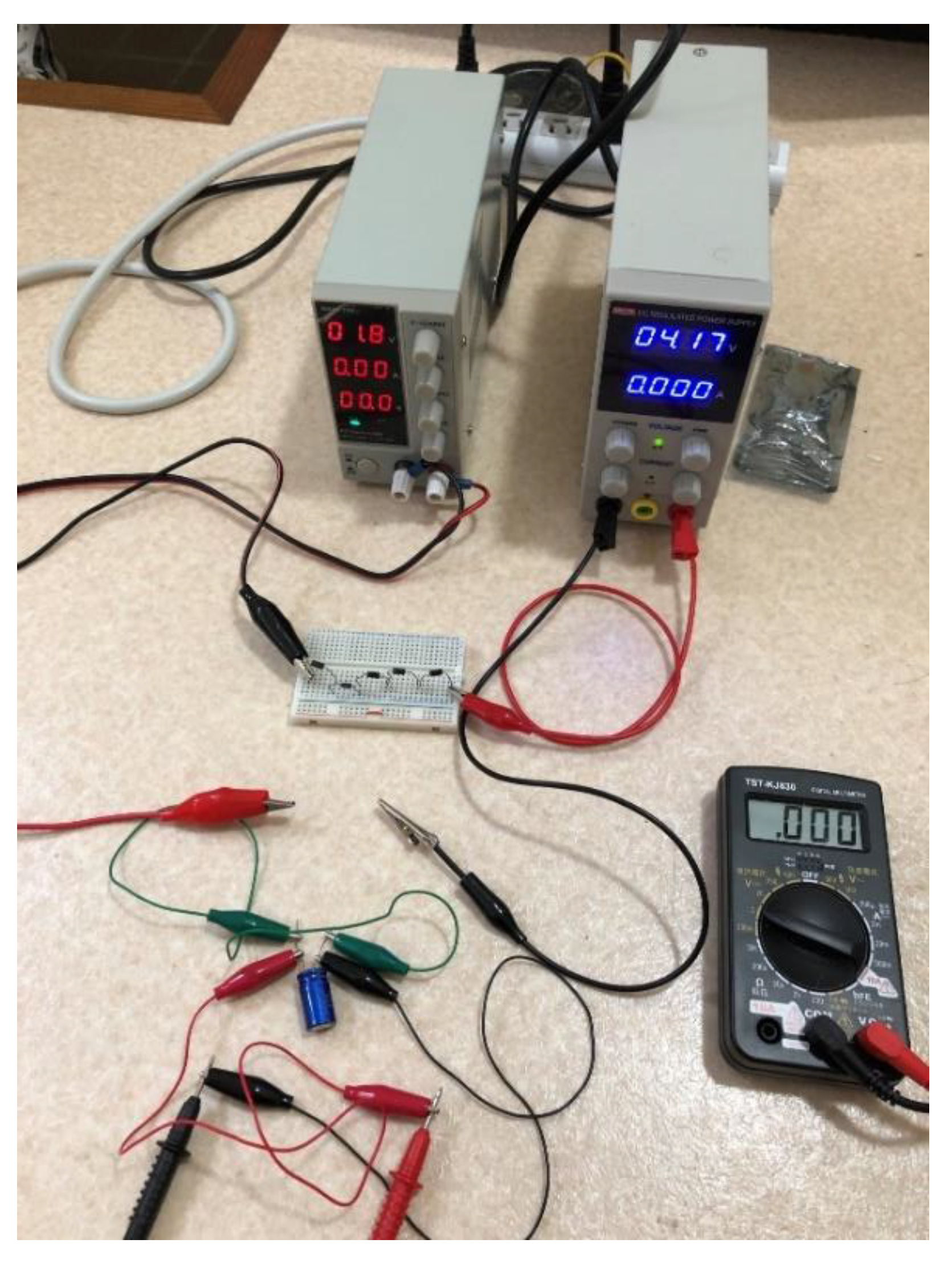
Figure 5-3.
Once the super-condenser is connected, we observe that the current from the current source (i.e., approximately 0.16 A) and the voltage (i.e., approximately 4.1 V) from the voltage source are revived. Note that the voltage from the current source is the same as that of the super-condenser (i.e., the voltmeter).
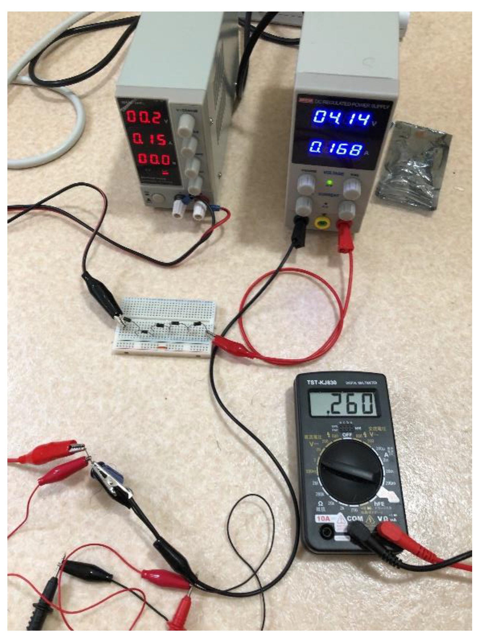
Figure 5-4.
The voltage of the charged condenser is approximately 0.8 V.
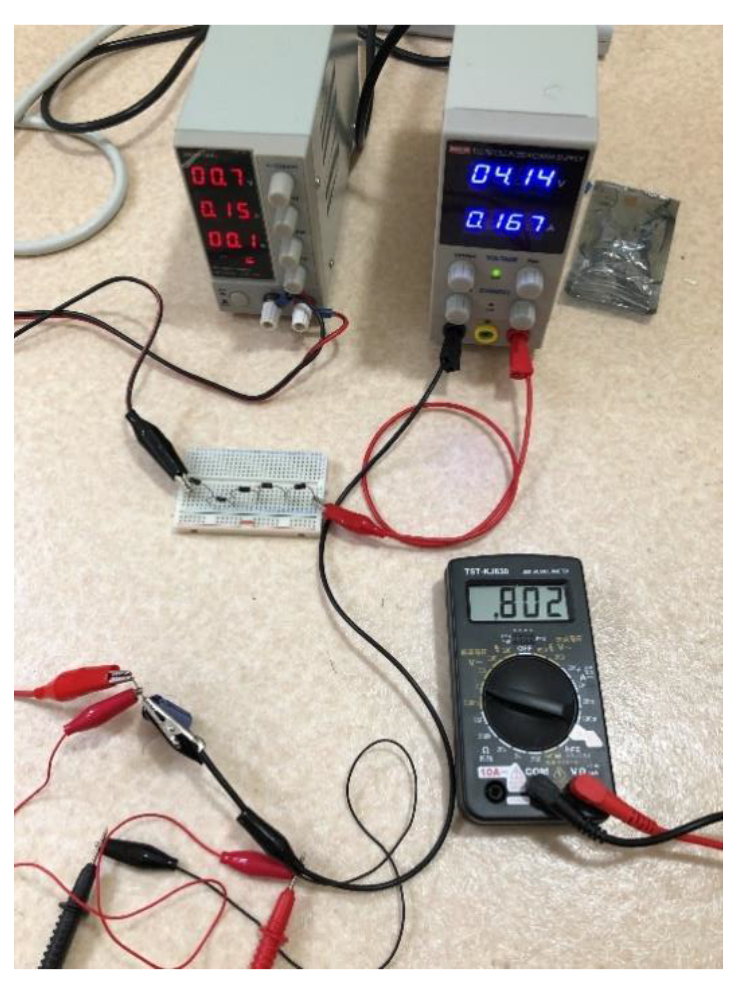
Figure 5-5.
The voltage of the charged super-condenser is approximately 2.1 V.
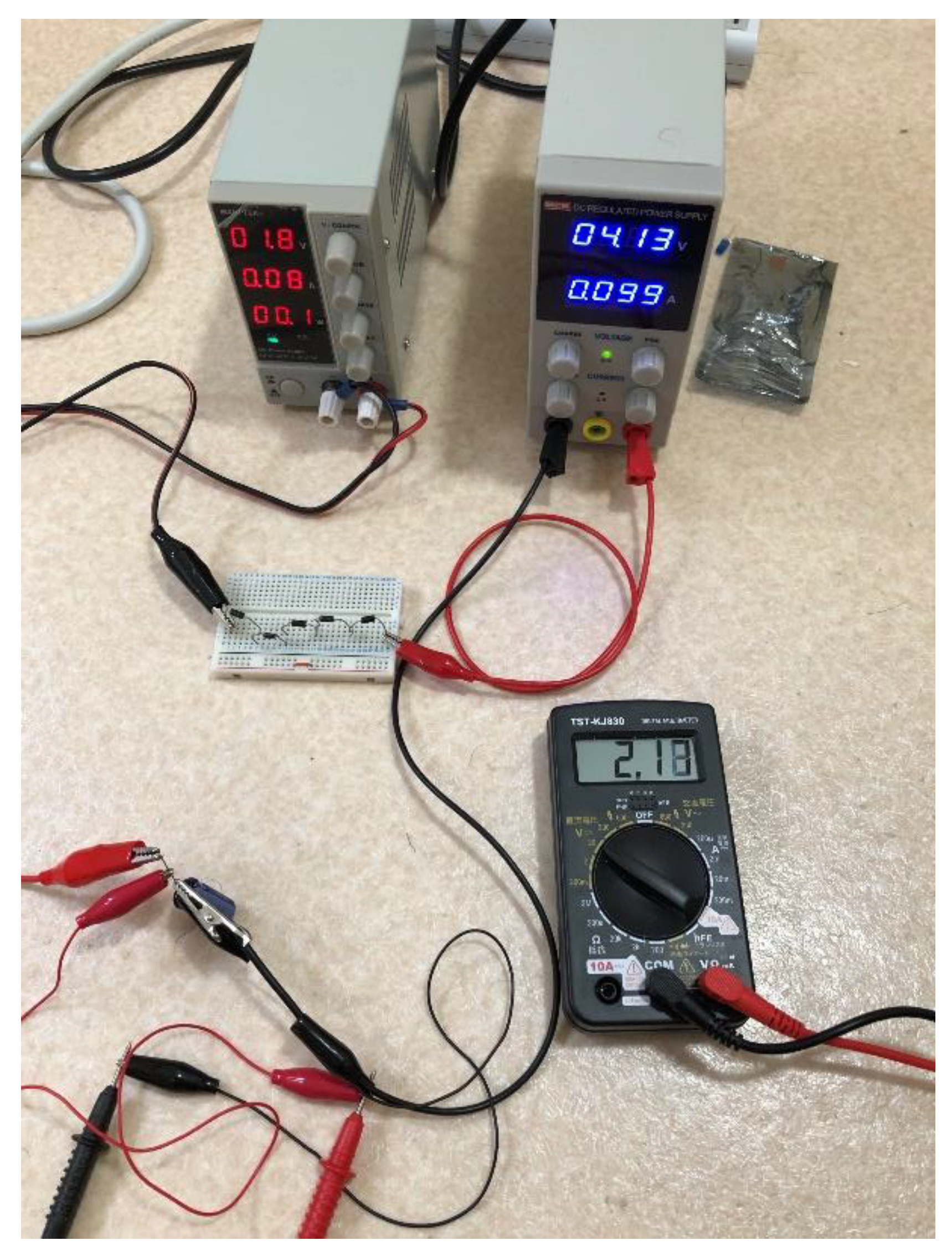
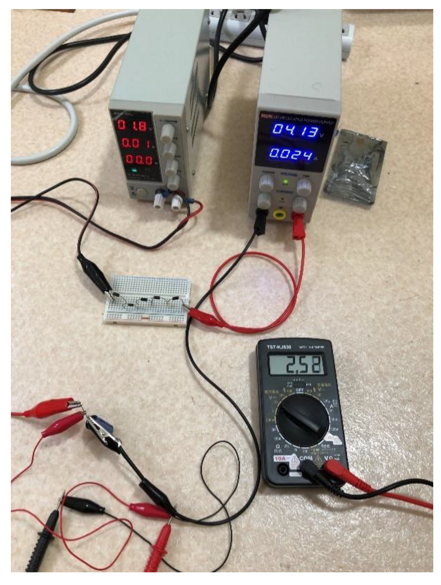
Figure 5-6.
Since the charging voltage was close to the standard voltage of 2.5 V, the experiment was forcibly stopped; that is, the charging was halted.
Figure 5-6.
Since the charging voltage was close to the standard voltage of 2.5 V, the experiment was forcibly stopped; that is, the charging was halted.
In Table 1, the comparisons of the theory and experiment regarding the charged voltage (vc) are presented. As indicated, the values are consistent, validating the assumption in Equation (2).
5. Discussion
Here, we consider the limitations of this system. For this system to work properly, a current source is required. That is, if the load is overly large, the CC source switches to the CV source immediately, implying that the system adopts the SS circuit only for small loads.
In this study, the generation of renewable energy was demonstrated. First, the proposed system employs a series circuit comprising current and voltage sources. With appropriate adjustment, the current source provides only current (J) without voltage and the voltage source supplies only voltage (V2) without current. Generally, electric power is a product of voltage and current. Thus, by the interaction between the voltage and current sources in the circuit, electric power ( [W]) is generated. Based on this, we successfully powered a load without external power supplies. Through this method, we confirmed that an LED and a super-condenser can work as loads. In our previous study [13], the same result was achieved, although the charging voltage of the super-condenser was relatively low. In this study, the following ingenuities were introduced:
- (A)
- Normal diodes were introduced. The larger the number of diodes, the larger the work voltage. This concept is similar to the “level shift” in electron circuits.
- (B)
- Thereafter, the load was inserted into the partially opened circuit, analogous to the introduction of switches.
Using this system, we could supply the right amount of energy in the right place and at the right time, potentially overcoming the challenges of the existing renewable-energy-generation systems. Moreover, as this system does not produce hazardous substances and CO2, it is highly environmentally friendly.
6. Conclusion
In this study, a renewable-energy-generation system was demonstrated. The proposed system consists of a current source and a voltage source connected in series, in addition to normal diodes. The current source supplies current without voltage, whereas the voltage source provides voltage without current. Consequently, the current from the current source and the voltage from the voltage source generate electric power. Employing this generated energy, we succeeded in powering an LED and storing energy in a super-condenser. However, note that this system cannot employ overly large loads. Future studies should focus on overcoming this limitation.
Additional information
This paper is not related to any competing interests such as funding, employment, and personal financial interests. Moreover, this paper is not related to nonfinancial competing interesting.
Acknowledgments
We thank Enago (www.enago.jp) for English language reviews.
References
- B. Wu et al, Renew. Sustain. Energy Rev, 135, 11037 (2021).
- A. Tyo et al, Entrep. Sustain., 7, 1514-1524 (2019).
- Dincer et al, Renew. Sustain. Energy Rev, 4(2), 157-175 (2000).
- M.R. Chehabeddine et al, Insights Reg. Dev., 4, 22-40 (2022).
- Adriaan van der Loos et al, Renew. Sustain. Energy Rev, 138, 110513 (2021).
- H. Obane et al, Renewable Energy, 160, 842-851 (2021).
- Sabishchenko et al, Energies, 13, 1776 (2020).
- M. Wierzbowski et al, Renew. Sustain. Energy Rev. 74, 51-70 (2017).
- C.-W. Wang et al, Energies, 13, 2629 (2020).
- T. Radavicius et al, Insights Reg. Dev. 3, 10-30 (2021).
- K. Akimoto et al, Energy and Climate Change, 2, p.100057 (2021).
- K.O. Yoro et al, Renew. Sustain. Energy Rev, 150, 111506 (2021) .
- S. Ishiguri. Preprints 2023, 2023061127. https://doi.org/10.20944/preprints202306.1127.v1. [CrossRef]
Figure 1.
Electric circuit symbols of the voltage and current sources.
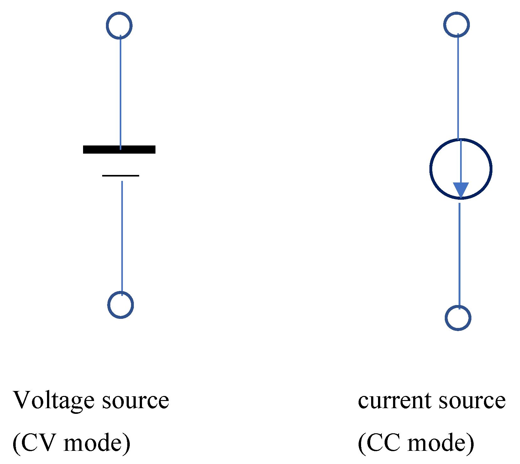

Table 1.
Comparison of the experimental and theoretical charge voltage values of the super-condenser.
Table 1.
Comparison of the experimental and theoretical charge voltage values of the super-condenser.
| V0 [V] | V2 [V] | Measurement vc [V] | Theory values vc [V] |
| 1.0 | 4.15 | 2.04 | 2.03 |
| 1.2 | 4.4 | 2.3 | 2.29 |
| 1.6 | 4.28 | 2.6 | 2.60 |
Disclaimer/Publisher’s Note: The statements, opinions and data contained in all publications are solely those of the individual author(s) and contributor(s) and not of MDPI and/or the editor(s). MDPI and/or the editor(s) disclaim responsibility for any injury to people or property resulting from any ideas, methods, instructions or products referred to in the content. |
© 2024 by the authors. Licensee MDPI, Basel, Switzerland. This article is an open access article distributed under the terms and conditions of the Creative Commons Attribution (CC BY) license (http://creativecommons.org/licenses/by/4.0/).
Copyright: This open access article is published under a Creative Commons CC BY 4.0 license, which permit the free download, distribution, and reuse, provided that the author and preprint are cited in any reuse.


