
Submitted:
07 August 2024
Posted:
08 August 2024
You are already at the latest version
Abstract
This paper presents and demonstrates the development of a new lightweight coating for aluminium alloy using a novel multicomponent alloy based on the AlSiMgCu system. This coating was applied using a newly designed approach that combined High-Velocity Oxy-Fuel (HVOF) and Plasma Spraying processes. This hybrid technique enables the deposition of coatings with enhanced performance characteristics. The microstructure was studied using optical microscopy (OM) and scanning electron with energy dispersive X-ray spectroscopy (SEM+EDS) microscopy, revealing good adhesion and compaction between the multicomponent coating and the A6061 substrate with 50 to 150 µm thickness. Vickers indentations were performed on the substrate and the new coating material, revealing a 50% improvement in the material's hardness compared to the casted alloy. Additionally, electrical conductivity measurements showed approximative x3.3 times values compared to the alloy in as-cast condition due to high solidification rates altering the morphology of the phases. Corrosion tests demonstrated a lower corrosion rate compared to other multicomponent aluminium alloys and similar to thermal treated A6061 alloy. Finally, tribological results obtained using ball on disc (BOD) test and laser scanning confocal microscopy, confirmed that the new multicomponent coating exhibited reductions in both friction coefficient and wear rate by more than 20% and 50%, respectively. This study demonstrates that using multi-component aluminium coatings could lead to developing of new automotive parts with enhanced properties for corrosion resistance, electrical conductivity, and wear conditions. Optimizing the thermal spraying parameters could further enhance the coating, achieving greater and more homogeneous thicknesses and yielding even higher performance properties.
Keywords:
coating
; plasma
; HVOF
; multicomponent aluminium alloy
; wear
; electrical conductivity
; hardness
; microstructure
1. Introduction
Protective coatings have proven effective in extending the lifespan of metallic structures and various parts used in multiple sectors including automation, with the recent trend to employ aluminium due to its fuel economy benefits [1]. Examples of these coatings include paints, organic and inorganic coatings, diffusion layers, metallic coatings applied via thermal spray, and galvanization [2]. Thermal spray is a highly versatile technology suitable for a wide range of applications and components. It is effective against wear, corrosion, and harsh high-temperature environments, and it enhances thermal efficiency, such as through insulation in aluminium engine cylinders [3]. Additionally, it is ideal for the repair and restoration of components [4].
Within the thermal spray techniques, several processes are noteworthy, including cold spray [4], HVOF, twin wire arc spraying, powder or detonation flame spraying, atmospheric plasma spraying, and arc spraying [5]. These methods differ in their application techniques such as the form of feedstock, material generation and transport medium velocity, transport medium temperature, and the unique properties they impart.
Among the advanced thermal spray techniques, HVOF technology stands out. This innovative method employs a combustion system with high-pressure fuel and oxidizer gases to induce detonation within the combustion chamber. This process partially or fully melts the material, accelerating it to adhere effectively to the substrate. The result is a high-velocity fluid haze with temperatures reaching up to 3000 ºC and supersonic speeds ranging between 400 and 1.000 m/s [6,7]. By optimizing parameters such as the fuel and oxygen flow rate, powder feed rate, spray distance, and carrier gas flow rate, it is possible to produce compact coatings with excellent resistance to abrasion, heat, friction, and wear [8,9,10]. Notably, thermal sprayed coating with a thickness of just 1 mm can achieve hardness values up to 2000 HV [11].
Compared to other thermal spray processes, HVOF coatings offer superior surface quality [12]. Additionally, when compared to other high-performance techniques like Atmospheric Plasma Spraying (APS), HVOF reduces the thermal degradation of the material [13].
Regarding the parameters, porosity which influences corrosion alongside nanocrystalline amorphous phases, and the hardness of the coating, will depend on the oxygen flow rate followed by powder feed rate and spray distance [12]. On the other hand, phase degradation, deposition efficiency, and bonding strength will also be affected principally by the spray distance [8]. Additionally, the angle of incidence impacts the final properties; higher preheating and a lower angle of incidence enhance the corrosion resistance of coatings [14]. Also, gun speed can be important in the final properties of the coating. Faster gun movement reduces torch dwell time, spraying less powder and lowering the coating temperature [15].
Certain studies have reported the application of HVOF techniques on aluminium alloy substrates [16,17,18,19,20,21], using ceramic materials such as carbides and oxides as the primary coating material due to their high melting points. In some cases, carbides and oxides are combined with metals like Co, Ni, and Cr to achieve low oxygen content and excellent adhesion properties [22].
In one study [23], WC10Co4C coating on an aluminium substrate resulted in reduced mechanical properties. Additionally, during friction tests, the carbide particles caused abrasion and fragmentation of the coating layers. The refinement of the microstructure, influenced by the feedstock powders, and the reduction of porosity, led to an increase in hardness from 68 HV up to 920HV in the Cr3C2 thermal spray coating on the Al-Si substrate [24]. Another study [25] demonstrated that an alumina coating up to 150 µm thick over an A6061 alloy resulted in hardness values ten times higher than the base. During the friction test with an alumina ball as the counter face, the substrate exhibited an abrasion wear mechanism and secondary adhesion, causing severe plastic deformation and delamination while the coating layer showed some cracks but not scratches or grooves characteristics of abrasion wear. On AlZn5.5MgCu aluminium alloy, AlCuFe quasicrystal was deposited as a coating [26] with the new materials showing friction coefficient values between 0.92 and 1.00. For A390 aluminium alloys, Al2O3 coating showed lower adhesion and unstable friction behaviour, with a dynamic coefficient of friction of 0.8, compared to WC-based coating with a coefficient of friction of around 0.6. Hardness values exceeded 1000 HV for WC-based coatings, while Al2O3-base coating reached 315 HV. Abrasion and adhesion wear mechanisms were observed in all cases [27]. Combining Al2O3 with Y2O3 and TiO2 in coatings has been reported to further enhance wear properties [28].
Some studies have explored aluminium-based coating on aluminium substrates, but there is limited information on the wear characteristics of ceramic and metallic coating on aluminium alloys. However, it has been demonstrated that metals such as aluminium are also beneficial for coating technologies, creating new demands for surface pre-treatment coatings for corrosion protection and paint adhesion in the automotive sector [29]. A notable recent development is the Alcoat project, which focuses on creating a new recycled aluminium coating for steel products [30].
A current trend and emerging opportunity that has garnered significant research attention over the past decade is the production of High Entropy Alloys (HEAs), also known as compositional complex alloys (CCAs) and multicomponent alloys [31]. The distinctiveness of these new alloys lies in their substantial improvement in mechanical properties. One of the fundamental concepts is to achieve a more disordered structure with five or more elements at or near equimolar composition, forming a solid solution phase, in contrast to conventional alloys, which are based on the central areas of phase diagrams [32]. Despite these new opportunities and their excellent mechanical properties [33,34], the large-scale production of Light High Entropy Alloys (LWHEAs) is limited, with vacuum die casting being the primary manufacturing process [35]. In some special cases, the investigated alloys include expensive elements such as Ag, which increases hardness and yield strength by more than 10% and elongation by 21% [36], or Nb [37]. However, the addition of these elements results in non-cost-effective alloys. Recently, it has been reported that rapid solidification processes can enhance the single-phase microstructures in these alloys and the absence of dendrite microstructure [38], although, in some instances, this requirement is not met, resulting predominantly in intermetallic phases [39]. New studies have demonstrated that, despite the limited understanding of intermetallic in HEA alloys, they can act as very effective second phases [40].
The development of multi-component materials based on aluminium alloys holds promise. Aluminium matrix composite brake drums and rotors have been used in vehicles such as the Lotus Elise, Volkswagen Lupo 3L, Chrysler Plymouth Prowler, and General Motors EV-1 due to their thermal and wear properties [41].
The use of HVOF technology is limited due to economic reasons, stemming from relatively expensive equipment and operational costs, particularly for powders [42]. From this perspective, employing secondary aluminium alloys for thermal spray powders could yield cost-effective results.
In this research, a new thermal spray process combining HVOF and plasma technologies is employed. This new device utilizes a thermal plasma to enhance the combustion process within the HVOF spray torch and incorporates an auxiliary cold gas to assist in controlling the process temperature. The use of thermal plasma to assist combustion aims to increase the flexibility of the spray system in terms of operating parameters and the range of materials that can be sprayed [43].
Additionally, the grain size of the coating influences the final mechanical properties. In this case, gas atomization has been selected as the method to convert a new multicomponent cast alloy into powder. This process provides grain sizes ranging from 10 µm to 150 µm [44]. Moreover, the alloy has been manufactured using the High-Pressure Die-Casting (HPDC) process, which also produces smaller grain sizes that are favourable for atomization [45].
It is noteworthy that due to oxidation, accelerated by process temperatures, these coatings can serve as effective thermal barrier coatings for components exposed to hot gases. This characteristic renders them suitable not only for transportation applications but also for hydrogen utilization.
2. Materials and Methods Experimental
2.1. Materials Substrate and Coating
A new multicomponent aluminium alloy based on the Al80Mg10Si5Cu5 system was used in the experimental study. This new alloy was obtained by HPDC foundry process that involves high velocities and takes place to microstructures with superior mechanical properties [46]. The initial as-cast condition phases included the aluminium matrix, primary and eutectic Mg2Si particles of size 20 and 5 µm, and copper-rich phases (Al2Cu and Al2CuMg) with sizes around 10 µm.
For the thermal spray process, the Al80Mg10Si5Cu5 alloy was converted into powder using gas atomization with a Leybold VIGA 2S atomizer. Argon was used at a pressure of 2.4 MPa and the melt temperature was set at 850 ºC. Subsequently, a qualitative and semiquantitative analysis was performed by averaging the composition from three measurements, each covering over 100 particles Figure 1 illustrates the irregular morphology of the powder obtained after atomization.
Finally, before thermal spraying the multicomponent material on the substrate, a sieving process was carried out with an optimum size distribution between 63 and 250 µm in 4 runs.
As part of the material substrate, a commercial extruded A6061 aluminium alloy was employed. This alloy is commonly used in components for the automotive industry [47]. Commercial plates with dimensions of 40 x 30 mm and a thickness of 5 mm were used. Before the coating process, the samples were ground up to 800 grit SiC paper, cleaned with propanol, and finally dried Table 1 collects the chemical composition and Table 2 the mechanical, electrical, and thermal properties of the two experimental alloys.
2.2. Plasma Coating
A newly designed, self-manufactured system utilizing the HVOAF technology, a combination of HVOF and plasma, was employed to coat the prepared A6061 aluminum alloy. This system, named Kombus+, was engineered and produced by Tecnalia. The Kombus + system is based on a supersonic combustion projection system with oxygen and air. The mixture of gas + air / O2 increases flows to maintain supersonic speed and pressure. Figure 2 illustrates the plasma equipment with the robot applying a coating to a sample.
The experimental parameters were specified as follows: the fuel flow rate was calibrated to 380 litres per minute with methane as the fuel gas, while the oxygen flow rate was set to 300 litres per minute. The airflow rate was regulated at 1,500 litres per minute, with an air pressure of 14 bar. The carrier flow rate was adjusted to 90 litres per minute. The powder feed rate was configured to 25%, with an incidence angle of 90 degrees. The spray gun stand-off distance was 300 mm for deposition on the substrate, and the gun speed was maintained at 0.9 meters per second. The system was operated at 250 revolutions per minute.
When measured with a pyrometer, the flame temperature reached 2000 ºC, while the substrate temperature was recorded at 200 ºC.
2.3. Hardness Study
To evaluate the hardness of the new material with the coating, Vickers indentations were conducted. The Vickers hardness was determined using a Vickers hardness tester model FV-700, selecting after several trials, the load of 10 kgf as the best option. Measurements were taken at the top, bottom, and the interface of the coating. Additionally, hardness measurements were taken on the substrate to ensure that the thermal process did not affect the mechanical properties of the base material. In total 3 samples were analyzed.
2.4. Dry Sliding Wear Behaviour
To investigate the tribological properties of the new coated aluminium alloy, dry sliding wear friction tests were conducted using a sphere-on-plate reciprocating configuration with a ball-on-disk (BOD) mode tribometer (MT2/60/NI/HT, Microtest S.A.). A total of 6 tests were performed: 3 tests on the coated material and 3 tests on the substrate without the coating. Alumina balls with a diameter of 6 mm and hardness values ranging between 1250 and 1700 HV, were used as counter-face bodies The use of alumina spheres as counter-face ensures that the mechanically mixed layer (MML), which is common when steel balls are used and typically contains Al-Fe-O, is not formed. This minimizes chemically driven aspects of adhesive wear due to reduced chemical adhesion [48], thereby facilitating the determination of wear properties [49]. The testing parameters employed during the sliding wear friction tests are summarized in Table 3. The selection of these parameters aligns with tribological studies conducted on other high-wear performance aluminium alloys [50].
After completing the BOD tests, the determination of the wear coefficient rate was conducted using 3D laser scanning confocal microscopy (DCM 3D, Leica). A total area of 20.8 x 20.2 mm and a height of 684 µm was measured using a 5X objective. At least 16 2D profiles were obtained using Leica map software. Additionally, for comparison, four radii of 2.5 x 1.8 mm and a height of 275 µm were measured using the same 5X objective. The total volume loss was calculated, and wear coefficients were obtained in mm³/N·m [51,52].
Images of the wear track and cross-sections of the wear tracks were captured and analyzed to identify the wear mechanisms, using optical microscopy (OM), scanning electron microscopy (SEM), and confocal microscopy (CM).
2.5. Electrical Conductivity
The electrical conductivity (EC) was assessed with a portable conductivity meter, an Autosigma 3000 model. This device employs the Eddy Current method to gauge conductivity and reports the results in the standard unit of %IACS (International Annealed Copper Standard). Conductivity measurements were performed on the newly coated material, with a minimum of five readings taken from the sample.
2.6. Corrosion Test
The general corrosion rate was determined using electrochemical techniques. Two different experiments, electrochemical impedance spectroscopy (EIS) and potentiodynamic polarization in the TAFEL region were conducted on the new as-cast multicomponent Al80Mg10Si5Cu5 alloy. The combined use of these two techniques has been reported in some studies as an alternative to avoid practical issues that often reduce their reliability [53]. The tests were performed in a 3.5 wt.% sodium chloride solution. Before each test, the samples were grinded and stabilized for open circuit potential (OCP) for 60 minutes, adhering to ASTM G5 guidelines.
3. Results
3.1. Microstructure of New Al80Mg10Si5Cu5 Coating on A6061 Alloy
Figure 3 shows the SEM images of the coated A6061 aluminium material with the Al80Mg10Si5Cu5 multicomponent alloy. Images revealed that the new coating achieved thicknesses ranging from 50 to 130 µm, though it was not completely homogeneous. The thickness of the developed coatings falls within the typical range obtained by thermal sprayed techniques (100-500 µm) [54], with the powder feed rate as the main parameter that influences the deposition rate, determining whether it is low or high [55].
EDS analysis, as presented in Table 4, indicated that while the new multicomponent alloy in its as-cast state exhibited four phases, the new coating displayed only two distinct phases. The primary phase corresponds to the aluminium matrix, appearing in grey colour (point 2). Light grey areas enriched with Mg, Si, and Cu (point 3) were observed, and correlated with the aluminium matrix with Mg2Si and part of Al2Cu phases. Additionally, white-colored phases were correlated with Al2CuMg phases with a splat pattern-like structure [28] at the grain boundaries of the aluminium matrix (point 4).
Due to the high cooling and solidification speeds of HVOAF process, the Al2Cu phase was not observed in the new coated material, transforming it into Al2CuMg phases, as observed in some previous works [56,57]. Moreover, the primary polygonal and eutectic globular Mg2Si phases also vanished, precipitating throughout the matrix. It is noted that the dissolution of Mg2Si phase is much more rapid than the one of Al2Cu and Al2CuMg [58].
Additionally, because the HVOAF process did not take place in a protective atmosphere, some oxides were detected. Some of these oxides were elongated and parallel to the substrate, potentially resulting in a higher hardness in the new coating [59]. These oxides could also act as lubricants during the sliding process [60]. Spherical pores, appearing as black spots within the coating, were identified, especially at the bottom of the coating. Using ImageJ software, it was demonstrated that the area of porosity was less than 2%, which is a low value compared to what is typically reported value for thermal spray coatings [61]. These small pores in HVOF spraying are typically due to shrinkage porosity [62]. According to the literature collected porosity is affected by fuel flow rate, powder rate, and the spray distance [8],[12],[55].
As can be appreciated in the image, it was demonstrated that the HVOAF process resulted in good adhesion between the substrate and the coating [10]. This process eliminates the need for post-treatments typically required to enhance adhesive strength in other thermal methods [4].
By analyzing at higher magnifications (x5.000) and applying an EDS line analysis (Figure 4) and a complementary EDS mapping for elemental analysis (Figure 5), the interface of the new coating was studied in more detail. The interface was especially enriched in copper, with aluminium, magnesium, and silicon as secondary elements, correlated with the presence of Al2CuMg phase. The Al2CuMg phase can serve as a crack initiation source [63]. However, its presence is advantageous in aluminium alloys [64] due to the higher strength and hardness values provided by the Al2CuMg phase [65] compared to the Al2Cu phase. Additionally, the deposition of this intermediate layer contributes to better adhesion of the coating to the substrate [24].
3.2. Hardness
Figure 6 shows the optical micrograph with an example of indentations performed on the substrate, the interface, and the top and bottom of the coating, along with the graphic displaying the obtained mean results and standard deviation. The size of the hardness track was smaller at the interface, resulting in a higher hardness of around 200 HV10. This corroborated the microstructure analysis, which showed the Al2CuMg phase precipitating at the interface, and this harder Al2CuMg phase provides higher hardness values [65]. Notably, no cracks were identified at the interface after the indentations were performed, typical of fragile phases. By comparing the hardness of the coating with that of the substrate, it was demonstrated that the new multicomponent Al80Mg10Si5Cu5 aluminium-based coated material significantly improved the hardness of the A6061 alloy achieving values of 133 HV10 ± 4.5, which is two times higher. In addition, it was shown that the new coating provided a similar value of hardness as the new multicomponent Al80Mg10Si5Cu5 alloy in its as-cast condition.
3.3. Tribological properties
Figure 7 illustrates the evolution of the coefficient of friction (COF) values measured for the experimental samples: A6061 substrate alloy with the coating based on the multicomponent Al80Mg10Si5Cu5 alloy, A6061 substrate alloy without the coating, and the multicomponent Al80Mg10Si5Cu5 alloy in its as-cast state. Initially, during the first stages, the friction coefficient showed high values for the A6061 substrate without the coating and the multicomponent Al80Mg10Si5Cu5 alloy in its as-cast state, with a maximum coefficient of friction exceeding 0.6. In contrast, the new coated material exhibited consistently lower values during the entire sliding test. Once the steady state was reached, both the multicomponent Al80Mg10Si5Cu5 alloy in its as-cast state and the A6061 alloy with the new coating showed a coefficient of friction with values around 0.4. On the other hand, the A6061 alloy without the coating maintained higher values, around 0.52, consistent with values reported in the literature for A6061 alloys [66]. The A6061 alloy without the coating also exhibited high fluctuations in the coefficient of friction, attributed to particle fracture, periodic accumulation [67], and elimination of debris on the wear surface during dry sliding contact [68,69]. It was demonstrated that the new coating based on the multicomponent Al80Mg10Si5Cu5 alloy reduced friction by approximately 23%. Furthermore, the comparison with the hardness values confirmed that samples with higher hardness exhibited lower values for friction coefficient during the sliding process [70].
Figure 8 displays the 2D and 3D profiles of the wear tracks on the A6061 aluminium alloy with (Figure 8a-Figure 8c) and without (Figure 8b-Figure 8d) the coating based on the new multicomponent Al80Mg10Si5Cu5 alloy. The coated material exhibited a width of 1 mm and a maximum depth of 60 µm, whereas the uncoated material showed a width of 1.6 mm and a depth of 120 µm. It was demonstrated that the A6061 alloy coated with the new multicomponent Al80Mg10Si5Cu5 alloy had a reduced width and depth of the wear track compared to the A6061 substrate alloy without the coating.
In Table 5, the mean values and deviations for the coefficient of friction (µ) at the state stage and the wear rate coefficient (K) for each case are compiled. The A6061 alloy without the coating exhibited the highest values for the coefficient of friction, which corresponds to the highest wear rate observed among the samples. In contrast, the sample with the new coating showed a significantly reduced wear rate, approximately 2.5 times lower than the uncoated sample. The wear rate for the sample with the coating was comparable to that of the Al80Mg10Si5Cu5 in its as-cast state. The wear rate observed in the new coated material indicated a mild wear regime, whereas the A6061 alloy without the coating exhibited values corresponding to a moderate to severe wear regime, as documented in the literature for aluminium alloys, particularly for A6061 alloys [71,72]. These values fall within the range reported for composite aluminium materials used in the manufacturing of pistons, cylinders, engine blocks, brakes, and power transfer system elements [41].
It is noteworthy that aluminium alloys can perform effectively under non-severe wear conditions, provided that delamination wear is effectively controlled [73].
To analyze the wear modes of the A6061 alloy with and without the coating based on the new multicomponent Al80Mg10Si5Cu5 alloy, the surfaces of the wear tracks surface were investigated as shown in Figure 9.
The wear track of the coated A6061 alloy consisted of ploughed areas, indicating an abrasion wear mechanism. In contrast, the A6061 alloy without the coating exhibited multiple wear mechanisms. In addition to ploughed areas, with wider scratches, some delaminated areas associated with cracks [74] were also visible on the wear track surface, indicating the presence of an adhesion mechanism [75,76,77]. The Al80Mg10Si5Cu5-based coating on A6061 alloy exhibited a low friction coefficient, high hardness, and moderately low surface energy. These characteristics result in anti-adhesive properties [78], making the coated alloy superior to uncoated A6061, which has a higher friction coefficient and lower hardness.
The results obtained are consistent with those reported in the literature for the A6061 alloy, which is characterized by grooves and ploughing due to abrasion and adhesion mechanisms [79,80], where delamination mode appears first as a substrate [81].
Figure 10 shows the cross-sectional microstructures of the A6061 alloy with the coating layer (Figure 10a and Figure 10c) and without the coating (Figure 10b and Figure 10d). It can be observed that after the sliding tests, the coating layer was still present on the coated A6061 alloy. By analyzing the samples with ImageJ software, it was determined that the highest thickness was around 60 µm, indicating that the coating had only worn by 40%. Additionally, no cracks were identified in the coating.
Consistent with the surface wear track analysis, the A6061 alloy without the coating exhibited delaminated areas on the subsurface [82] as a result of its lower hardness. The transition from mild to severe wear is marked by a shift from localized failure [83]. In conclusion, the surface and cross-sectional images of the wear track images agree with the wear rates and friction coefficient results discussed above.
3.4. Electrical Conductivity
Table 6 collects the value for electrical conductivity obtained in the new multicomponent Al80Mg10Si5Cu5-based coated A6061 alloy. According to the results, the conductivity value obtained was slightly lower than that of pure aluminium (less than 10%), and very similar to that of the substrate A6061 alloy [84], as shown in Table 2. Additionally, the electrical conductivity of the coated material was 3.3 times higher than that of the Al80Mg10Si5Cu5 multicomponent alloy in its as-cast state, as shown in Table 2. This increase in conductivity is attributed to the thermal process and the high solidification rates involved in the coating process [85].
3.5. Corrosion Test
The parameters obtained through the tests conducted were: the corrosion potential (Ecorr) in volts, the corrosion current density (Icor) in µA/cm2, and the corrosion rate (Cor. Rate) in mm/year [87,88], which are presented in Table 7 and Table 8.
By comparing the obtained values by both methods, the multicomponent Al80Mg10Si5Cu5 alloy employed as coating material showed lower corrosion resistance than those reported in the literature for conventional and multicomponent aluminum alloys [89]. High levels of silicon and copper typically contribute to poor corrosion resistance However, in the new as-cast Al80Mg10Si5Cu5 alloy, the addition of a higher amount of copper compared to traditional aluminium alloys not only enhances hardness properties but also improves other material characteristics, such as the corrosion resistance.
3.6. Relation between Microstructure, Solidification Rate, and Electrical Conductivity
After analyzing the various results obtained, in this section, a study is conducted to investigate how the solidification temperature of the materials influences their microstructural properties, composition, and electrical conductivity. To provide a more comprehensive analysis, we have not only reviewed the experimental samples examined so far (as-cast Al80MgSi5Cu5 obtained by HPDC and Al80MgSi5Cu5-based coating produced by thermal spray) but also evaluated new samples solidified with different cooling rates: one from the Al80MgSi5Cu5 alloy solidified by gravity sand casting and another from the same alloy solidified in a metal die-cast, also using gravity.
Figure 11 illustrates the microstructures of the multicomponent Al80Mg10Si5Cu5 alloy as a function of different solidification rates [96,97,98,99,100]. For the sample solidified in a sand mould by gravity casting, the cooling rate was the lowest, approximately 0.1 ºC/s. In this case, the aluminium matrix displayed polygonal Mg2Si as the primary phase, eutectic Mg2Si with a fine polygonal morphology, blocky Al2Cu, and finally Al2CuMg. As the cooling rate increased during solidification in the gravity die-cast (around 1 ºC/s), some of the fine polygonal eutectic Mg2Si transformed into a Chinese script-like structure. Additionally, the phases of Al2Cu and Al2CuMg displayed different morphology, with Al2Cu appearing as lamellar and Al2CuMg as blocky shapes [101], both solidifying particularly at the grain boundaries. When the HPDC process was employed to obtain the Al80Mg10Si5Cu alloy with cooling rates exceeding 100 ºC/s, the polygonal phases of Mg2Si remained, but the eutectic Mg2Si solidified with a globular shape and smaller particles. Both Al2Cu and Al2CuMg also appeared in smaller sizes and were located at the grain boundaries of the Al phase. Finally, when the Al80Mg10Si5Cu alloy was produced by thermal spray with cooling rates around 106 ºC/s, small particles of Mg2Si were dispersed throughout the matrix. Additionally, the Al2Cu phase was not detected, with only the presence of the Al2CuMg phase precipitated in a splat pattern-like structure, particularly at the interfaces.
The chemical composition of each constituent in the multicomponent Al80Mg10Si5Cu alloy, based on the manufacturing process and cooling rate, is summarized in Table 9. As shown, the morphology and copper content in the Mg2Si and Al2CuMg phases increased with the cooling rate, resulting in a supersaturated copper solution. Consequently, due to reduced solute levels in the aluminium matrix and microstructural transformations, electrical conductivity increased [102,103,104].
4. Discussion
It has been demonstrated that using new multicomponent Al80Mg10Si5Cu5 aluminium alloys as a coating material for aluminium alloys improves mechanical, electrical, and tribological properties. Additionally, there was a slight improvement in corrosion resistance. The newly designed HVOAF process provided a high-quality coating with a thickness of up to 130 µm, though some pores were presented at the bottom of the coating, accounting for less than 2% of the area. These pores are characteristic of this process. This thermal process requires experienced handling and optimization of parameters to achieve consistent coating quality. Parameters such as oxygen flow rate, spray distance, and powder feed rate can be optimized to improve porosity and coating thickness.
Microstructure and chemical analysis results indicated good adhesion between the substrate and the coating. The high solidification rates led to fewer phases and a finer microstructure, resulting in the disappearance of the Al2Cu phase and the precipitation of Mg2Si throughout the matrix. In the interface area, a high presence of elemental copper precipitated as the Al2CuMg phase, providing high hardness without cracking.
Hardness results demonstrated a 50% increase in the new multicomponent-based coated material compared to the A6061 substrate alloy, reaching values up to 220 HV.
Tribological property results showed that the friction coefficient decreased by more than 20% in the new multicomponent alloy-based coated material compared to the A6061 substrate alloy, achieving a steady-state friction coefficient value of 0.40. This value was similar to that observed for the new multicomponent alloy in its as-cast state. Additionally, the wear coefficient also decreased significantly, approximately 2.5 times lower than that of the uncoated sample.
The wear rate coefficient and examination of the microstructure of the wear track surface and cross-sectional surface in the new coated material indicated mild wear conditions characterized by abrasion as the principal wear mechanism. In contrast, the substrate without the coating exhibited moderate to severe wear, showing delaminated areas alongside ploughed areas attributed to a combination of abrasion and delamination mechanisms.
Comparing the hardness values of the experimental alloys revealed that samples with higher hardness demonstrated a lower coefficient of friction during the sliding process. Additionally, it was observed that samples with significantly higher values for the coefficient of friction corresponded to the highest wear rate. However, it was noted that samples with a similar coefficient of friction did not necessarily exhibit a linear relation with the wear rate.
The electrical conductivity results showed a significant improvement (x3.3 times) compared to the multicomponent alloy in its as-cast state. The conductivity values approached those of the A6061 substrate and were comparable to pure aluminum alloy. The analysis demonstrated a strong influence of the cooling rate and morphology of the constituents on electrical conductivity.
Corrosion resistance results demonstrated that the multicomponent alloy had higher values compared to other conventional and multicomponent aluminum alloys and were also higher than those of heat treated A6061 alloy. However, they were higher than the values for A6061 alloy in its as-cast state. Parameters such as preheating, and angle of incidence should be investigated to further increase the corrosion resistance of the coating.
5. Conclusions
A new coated material based on a new multicomponent aluminum alloy has been developed, featuring enhanced mechanical, electrical, and tribological properties.
Future work will focus on optimizing some thermal spray parameters to further enhanced specific properties. To achieve thicker coatings, the powder feed rate will be investigated. Additionally, the angle of incidence and preheating will be optimized, as a lower angle of incidence has been shown to improve corrosion resistance.
Furthermore, the application of the Al80Mg10Si5Cu5 multicomponent alloy on the other types of aluminum substrate will be investigated.
Finally, studies are anticipated to evaluate these high-performance properties under real conditions and in casting parts.
Author Contributions
Conceptualization: E.V. and I.V; methodology: C.V. and J. A.; validation: E.V., I.V., J.A., T.G., N.B., I.H.; investigation: E.V., I.V. J.A.; writing—original draft preparation: E.V., I.V. J.A., review and editing: T.G., N.B.; supervision: I.V., J.A. project administration: E.V. I.V. funding acquisition: I.V., J.A. All authors have read and agreed to the published version of the manuscript.
Funding
This work has been partially funded by the Basque Government through the ELKARTEK KK-2020_00047 (CEMAP), KK-2022_00082 (MINERVA), and KK-2023/00020 (DESGAS).
References
- Tisza M: Czinege I. Comparative study of the application of steels and aluminium in lightweight production of automotive parts. Int. J. Lightweight Mater. Manuf. 2018, 1, 229-238. [CrossRef]
- Hanif H.; Wang T.; Su L.; Li H.; Zhu Q.; Yang A.; Li Z.; Wang W.; Zhu H. In Situ Thermal Interactions of Cu-Based Anti-Corrosion Coatings on Steel Implemented by Surface Alloying. Coating 2024, 14, 722-739. [CrossRef]
- Barbezat G. Application of thermal spraying in the automobile industry. Surf. Coat. Technol. 2006, 201, 2028-2031. [CrossRef]
- Sun W.; Wei-Yee A.; Wu K.; Yin S.; Yang X.; Marinescu I.; Liu E. Post-Process Treatments on Supersonic Cold Sprayed Coatings: A Review, Coatings 2020, 10, 123. [CrossRef]
- Gaur U.; Kumari E. Applications of Thermal Spray Coatings: A Review. J. Therm. Spray Technol. 2024, 4, 106-114. [CrossRef]
- Bhatia A. Thermal Spraying Technology and Applications. Course from the US Corps of Engineers, Publication EM 1110-2-3401, Available online: https://www.cedengineering.com/userfiles/T04-002%20-%20Thermal%20Spraying%20Technology%20and%20Applications%20-%20US.pdf.
- Miguel J.R.; Guilemany J.M.; Carbonell H. La Proyección Térmica de Alta Velocidad (HVOF) y Plasma: Qué Son y Para Qué Sirven. Conference: Jornadas sobre Tecnologías de Fabricación en la Industria, June 1197, Ferrol, Spain.
- Raza A.; Ahmad F.; Badri T.M.; Raza M.R.; Malik K. An Influence of Oxygen Flow Rate and Spray Distance on the Porosity of HVOF Coating and Its Effects on Corrosion-A Review. Materials (Basel). 2022, 15, 6329- 6354. [CrossRef]
- Taltavull C.; López A.J.; Torres B.; Atrens A.; Rams J. Optimisation of the high velocity oxygen fuel (HVOF) parameters it is factible to produce effective corrosion control coatings on AZ91 magnesium alloy. Materials and Corrosion 2014, 66-423-433. [CrossRef]
- Picas J.A.; Rilla A.F.; Martín E. Mejora de la resistencia al desgaste de aleaciones de aluminio mediante recubrimientos obtenidos por proyección térmica HVOF. Rev. Metall. 2005, 41. [CrossRef]
- Recubrimientos mediante proyección térmica: comparativa frente a otras tecnologías. Departamento técnico de TMCOMAS 2016. Available online: https://www.interempresas.net/TTS/Articulos/156162-Recubrimientos-mediante-proyeccion-termica-comparativa-frente-a-otras-tecnologias.html.
- Murugan K.; Ragupathy A.; Balasubramanian V.; Sridhar K. Optimizing HVOF spray process parameters to attain minimum porosity and maximum hardness in WC–10Co-4Cr coatings. Surf. Coat. Technol. 2014, 247, 90-102. [CrossRef]
- Fernández J.; Gaona M.; Guilemany J.M. La Proyección Térmica de Alta Velocidad (HVOF): Una Alternativa a la Proyección por Plasma de Hidroxiapatita. Sociedad Española de Materiales 2006, 1, 1109-112.
- Vanat K.J.; Cortés R.S.; Marenda A.G. Microstructural Analysis of Aluminum Coatings Deposited by HVOF Process on Complex Surfaces. Conference: International Thermal Spray Conference – ITSC, May 2018. [CrossRef]
- Pulido N.; García S.; Campo M.; Rams J.; Torres B. Application of DOE and ANOVA in optimization of HVOF spraying parameters in the development of new Ti coatings. J. Therm. Spray Technol. 2020, 29, 4. [CrossRef]
- Picas J.A.; Rilla A.F.; Martín E. HVOF thermal sprayed coatings on aluminium alloys and aluminium matrix composites. Surf. Coat. Technol. 2005, 200, 1178-1181. [CrossRef]
- Picas J.A.; Menargues S.; Martin S.; Colominas C.; Baile M.T. Characterization of duplex coating system (HVOF + PVD) on light alloy substrates. Surf Coat Technol. 2016, 318. [CrossRef]
- HVOF Aluminum Bronze. Available online: https://www.thermalspray.com/thermal-spray-coatings/spray-coating-materials/hvof-materials/hvof-aluminum-bronze/.
- Sobolev V.V.; Guilemany J.M.; Calero J.A. Formation of structure of WC-Co coatings on aluminum alloy substrate during high-velocity oxygen-fuel (HVOF) spraying. J. Therm. Spray Technol. 1995, 4, 401-407. https://doi.org10.1007/BF02648642.
- Pradeep G.S.; Sunkad S.; Jogeshwar R.; Keshavamurthy R.; Tambrallimath V.; Jangam S.; Basheer D. Experimental Investigations on Erosion-Corrosion Characteristics of HVOF-Sprayed WC-10% Ni Coatings Deposited on Aluminum Alloy. Adv. Mater. Sci. Eng. 2023, 1, 8533871. [CrossRef]
- Magnani M.; Suegama P.H.; Espallargas N.; Fugivara C.S.; Dosta S.; Guilemany J.M. Corrosion and Wear Studies of Cr3C 2NiCr-HVOF Coatings Sprayed on AA7050 T7 Under Cooling. J. Therm. Spray Technol. 2009, 18, 353-363. [CrossRef]
- Moreira F.; Ferreira P.M.; Silva R.J.C.; Santos T.G.; Vidal C. Aluminium-based dissimilar alloys surface composites reinforced with functional microparticles produced by upward friction stir processing. Coating 2023, 13, 962-980. [CrossRef]
- Koutsomichalis A.; Vardavoulias M.; Vaxevanidis N.M. HVOF sprayed WC-CoCr coatings on aluminum: tensile and tribological properties. OP Conference Series Materials Science and Engineering 2017, 174, 012062. [CrossRef]
- Richert M.; Ksiazek M.; Leszczyńska-Madej B.; Nejman I.H.; Grzelka R.; Palka P. The Cr3C2 thermal spray coating on Al-Si substrate. J. Achiev. Mater. Manuf. Eng. 2010, 38, 95-102.
- Ernesto T.; Garza-Montes-de-Oca N.F.; Pérez A.; Hernandez-Rodriguez M.A.L.; Hernández A.J.; Colás R. Wear of an aluminium alloy coated by plasma electrolytic oxidation. Surf. Coat. Technol. 2012, 206, 2213-2219. [CrossRef]
- Torskaya E.V.; Morozov A.V.; Malyshev V.N.; Shcherbakova O.O. Processing and Tribological Properties of PEO Coatings on AlZn5.5MgCu Aluminium Alloy with Incorporated Al-Cu-Fe Quasicrystals, Ceramics 2023, 6, 858-871. [CrossRef]
- Bang J.; Lee E. Enhancing wear resistance of A390 alumnium alloy: A comprehensive evaluation of Thermal Sprayed WC, CrC and Al2O3 coating. Coatings 2024, 14, 853. [CrossRef]
- Medricky J.; Lukac F.; Csaki S.; Houdkova S.; Barbosa M.; Tesar T.; Cizek J.; Musalek R.; Kovarik O.; Charska T. Improvement of Mechanical Properties of Plasma Sprayed Al2O3–ZrO2–SiO2 Amorphous Coatings by Surface Crystallization. Materials 2019, 12, 3232. [CrossRef]
- Doerre M.; Hibbitts L.; Patrick G.; Akafuah N.K. Advances in Automotive Conversion Coatings during Pretreatment of the Body Structure: A Review, Coatings 2018, 8, 405. [CrossRef]
- The Alcoat project. Available online.: https://icn2.cat/en/news/5126-the-alcoat-project-will-enhance-steel-construction-safety-using-recycled-aluminium.
- Balaji V.; Anthony X. Development of high entropy alloys (HEAs): Current trends, Heliyon 2024, 10, e26464. [CrossRef]
- Bilbao Y.; Trujillo J.J.; Vicario I.; Arruebarrena G.; Hurtado I.; Guraya T. X-ray Thermo-Diffraction Study of the Aluminum-Based Multicomponent Alloy Al58Zn28Si8Mg6, Materials 2022, 15, 5056. [CrossRef]
- Yang X.; Chen S.; Cotton J.D.; Zhang Y. Phase stability of low-density, multiprincipal component alloys containing aluminium, magnesium, and lithium, The journal of the Minerals, Metals & Materials Society 2014, 66, 2009. [CrossRef]
- Sanchez J.M.; Vicario I.; Albizuri J.; Guraya T.; Koval N.E.; García J.C. Compound formation and microstructure of As-cast high entropy aluminiums, Metals 2018, 8, 167. [CrossRef]
- Kumar A.; Gupta M. An Insight into Evolution of Light Weight High Entropy Alloys: A Review, Metals 2016, 6, 199. [CrossRef]
- Wang Y.; Wu X.; Cao L.; Tong X.; Zhu Q.; Sonhbai T.; Song H.; Guo M.X., Effect of Ag on aging precipitation behavior and mechanical properties of aluminum alloy 7075, Materials Science and Engineering A 2020; 804(4), 140515. [CrossRef]
- Nwaeju C.C.; Nnuka E.E., Effect of niobium addition on the structure and mechanical properties of aluminum bronze, International Journal of Research in Advanced Engineering and Technology 2015, 1(2), 70.
- Shao Y.; Guo P.; Liang N.; Cheng S.; Wang J.; Xu F. Microstructure refinement and enhanced mechanical properties in rapid-quenched MnCrFeCoNi high-entropy alloy, Heliyon 2023, 9, e22530. [CrossRef]
- Liu J.; Wang X.; Singh A.P.; Xu H.; Kong F.; Yang F. The Evolution of Intermetallic Compounds in High-Entropy Alloys: From the Secondary Phase to the Main Phase. Metals 2021, 11, 2054. [CrossRef]
- Tsai M.H.; Tsai R.C.; Chang T.; Huang W.F. Intermetallic Phases in High-Entropy Alloys: Statistical Analysis of their Prevalence and Structural Inheritance. Metals 2019, 9, 247. [CrossRef]
- Vencl A.; Rac A.; Bobic I. Tribological Behaviour of Al-Based MMcs and Their Application in Automotive Industry. Tribol. Ind. 2004, 26, 31-38.
- Sarjas H.; Goljandin D.; Kulu P.; Mikli V.; Surzhenkov A.; Vouristo P. Wear Resistant Thermal Sprayed Composite Coatings Based on Iron Self-Fluxing Alloy and Recycled Cermet Powder. Mater. Sci. 2012, 18, 34-39. [CrossRef]
- Martinez B.; Mariaux G.; Vardelle A.M.; Barykin G.; Parco M. Numerical Investigation of a Hybrid HVOF-Plasma Spraying Process. J. Therm. Spray Technol. 2009, 18, 909-920. [CrossRef]
- Descripción general de la tecnología de atomización de metales. Available online: https://met3dp.com/es/overview-of-metal-atomization-technology/.
- Jeon M.; Lee E. Effect of grain size on residual stress in AlSi10MnMg alloy. JAMET 2023, 47, 195-201. [CrossRef]
- Tialong Z.; Zhu J.; Yang T.; Luan J.; Kong H.L.; Liu W.; Cao B.; Wu S.; Wang D.; Wang Y.; Liu C.T., A new α + β Ti-alloy with refined microstructures and enhanced mechanical properties in the as-cast state, Scripta Materialia 2022, 207, 114260. [CrossRef]
- The Use of 6061 Aluminum Alloy in Cars. Available online: http://www.autoaluminumsheet.com/a/the-use-of-6061-aluminum-alloy-in-cars.html.
- Ghazali M.J.; Rainfoth W.M.; Omar M.Z. A comparative study of mechanically mixed layers (MMLs) characteristics of commercial aluminium alloys sliding against alumina and steel sliders, Journal of Materials Processing Technology 2008, 201, 662-668. [CrossRef]
- Ghazali M.J.; Rainforth W.M.; Jones H. The wear of wrought aluminium alloys under dry sliding conditions, Tribology International 2007, 40, 160–169. [CrossRef]
- Timelli G.; Fabrizi A.; Vezzù S.; De Mori A. Design of Wear-Resistant Diecast AlSi9Cu3(Fe) Alloys for High-Temperature Components, Metals 2020, 10, 1-16. [CrossRef]
- Torres A.; Hernández A.; García A.; Viesca J.L.; González R.; Hadfield M. Use of optical profilometry in the ASTM D4172 standard, 2011, 271 (11–12), 2963-2967. [CrossRef]
- Pawlus P.; Dzierwa A. Wear Analysis of Discs and Balls on a Micro-Scale, Tehnički Vjesnik 2018, 25 (2), 299-305. [CrossRef]
- Park K.; Chang B.Y.; Hwang S. Correlation between Tafel Analysis and Electrochemical Impedance Spectroscopy by Prediction of Amperometric Response from EIS. ACS Omega 2019, 4 (21), 19307–19313. [CrossRef]
- Berger L.M. Application of hardmetals as thermal spray coatings. IJRMHM 2015, 49, 350-364. [CrossRef]
- Vignesh S.; Shanmugam K.; Balasubramanian V.; Sridhar K. Identifying the optimal HVOF spray parameters to attain minimum porosity and maximum hardness in iron based amorphous metallic coatings. Defence Technology 2017, 13, 101-110. [CrossRef]
- Belov N.A.; Avksenteva N.N. Quantitative analysis of the Al –Cu –Mg – Mn – Si phase diagram as applied to commercial aluminum alloys of series 2xxx, Metal Science and Heat Treatment 2013,55. [CrossRef]
- Mondal C.; Mukhopadhyay A.K. On the nature of T(Al2Mg3Zn3) and S(Al2CuMg) phases present in as-cast and annealed 7055 aluminum alloy, Materials Science and Engineering: A 2005, 391(1-2), 367. [CrossRef]
- Zhang M.; Tian Y.; Zheng X.; Zhang Y.; Chen L.; Wang J. Research Progress on Multi-Component Alloying and Heat Treatment of High Strength and Toughness Al–Si–Cu–Mg Cast Aluminum Alloys. Materials 2023, 16, 1065. [CrossRef]
- Camara A. HVFO y APS. Available online: https://es.scribd.com/document/424202926/HVOF-y-APS.
- Bhaskaran R.; Supekar R.; Morteza S.; Wang W.; Zou Y.; McDonald A.; Mostaghimi J.; Stoyanov, P. High-Entropy Alloy Coatings Deposited by Thermal Spraying: A Review of Strengthening Mechanisms, Performance Assessments and Perspectives on Future Applications, Metals 2023, 13, 579. [CrossRef]
- Habib K.A.; Cano D.L.; Serrano-Mira J.; rayon E.; Dosta R.S. Impact of Microstructure on Remelting Parameters and Mechanical Behavior of Thermally Sprayed NiCrBSi Coating. J. Therm. Spray Technol. 2024, 33, 290-307.
- Sobolev V.V.; Guilemany J.M. Investigation of Coating Porosity Formation during High Velocity Oxy-Fuel (HVOF) Spraying. Materials letters 1994, 18, 304-308. [CrossRef]
- Wen K.; Yan H.; Yan L.; Liu H.; Xiao W.; Li Y.; Gao G.; Liu R.; Ren W. Evolution of S(Al2CuMg) Phase During Fabrication Process and its Influence on Mechanical Property in a Commercial Al-6.5Zn-2.4Mg-2.2Cu Alloy. Advances in Machinery, Materials Science and Engineering Application IX, 2023, 155-165. [CrossRef]
- Kralik R.; Battosova L.; Kihoulou B.; Preilser D.; Cieslar M. High-Temperature Phase Transformations in Al-Li-Cu-Mg-Zr-Sc Alloy Studied via In Situ Electron Microscopy. Crystals 2024, 14, 136. [CrossRef]
- Zhang J.; Huang Y.N.; Mao C.; Peng P. Structural, elastic and electronic properties of θ (Al2Cu) and S (Al2CuMg) strengthening precipitates in Al–Cu–Mg series alloys: First-principles calculations. Solid State Commun. 2012, 152, 2100-2104. [CrossRef]
- Al-Qutub A.M.; Khalli A.; Saheb N.; Hakeem A.S. Wear and friction behavior of Al6061 alloy reinforced with carbon nanotubes. Wear 2012, 297, 752-761. [CrossRef]
- Rapoport L.; Moshkovich A.; Perfilyev V.; Lapsker I.; Kugler M., Kailer A.; Renz A.; Hollstein T. High temperature friction behavior of CrVxN coatings. Surf. Coat. Technol. 2014, 238, 207-215. [CrossRef]
- Joseph J.; Haghdadi N.; Shamlaye K.; GHodgson P.D.; Barnett M.; Fabijanic D. The sliding wear behaviour of CoCrFeMnNi and AlxCoCrFeNi high entropy alloys at elevated temperatures, Wear 2019. [CrossRef]
- Wu J.M.; Lin S.J.; Yeh J.W.; Chen S.K.; Huang Y.S.; Chen H.C. Adhesive wear behavior of AlxCoCrCuFeNi high-entropy alloys as a function of aluminum content, Wear 2006, 261, 53-519. [CrossRef]
- Michalak M.; Sokolowski P.; Szala M.; Walczak M.; Latka L.; Toma F.L.; Bjorklund S. Wear Behavior Analysis of Al2O3 Coatings Manufactured by APS and HVOF Spraying Processes Using Powder and Suspension Feedstocks, Coatings 2021, 11, 879. [CrossRef]
- Shyan J.; Lin C.; Kuen Y.; Huang E.W.; Fu K.; Lee S. The combination of rolling-and-T6-treatments with Al 2 O 3 -reinforcing- particles effect on A6061 metal-matrix composites. Department of Materials Science and Engineering 2016, 230,233-239. [CrossRef]
- Elmadagli M.; Perry T.; Alpas A.T. A parametric study of the relationship between microstructure and wear resistance of Al–Si alloy, Wear 2007, 262, 79–92. [CrossRef]
- Zhang J.; Alpas A.T. Transition between mild and severe wear in aluminium alloys. Acta Mater. 1997, 45, 513–528. [CrossRef]
- Li H.; Jiao L.; Xu R.; Li F.; Lu S.B.; Qiao Y.P.;Li C.Y. Surface Wear Behavior and Friction and Wear Mechanism Studies of A356/3 wt.% Al 3 Zr Composites. J. MATER. ENG. PERFORM. 2021, 30. [CrossRef]
- Silvello A.; Torres E.; Rua E.; Garcia I. Microstructural, Mechanical and Wear Properties of Atmospheric Plasma-Sprayed and High-Velocity Oxy-Fuel AlCoCrFeNi Equiatomic High-Entropy Alloys (HEAs) Coatings. J. Therm. Spray Technol. 2023, 32, 425-442. [CrossRef]
- Khana V.K. Adhesion–delamination phenomena at the surfaces and interfaces in microelectronics and MEMS structures and packaged devices. J. PHYS. D. 2011, 44, 034004. [CrossRef]
- Olea-Mejia O.; Brostow W.; Buchman E. Wear Resistance and Wear Mechanisms in Polymer + Metal Composites. J.N.N. 2010, 10, 8524-8530. : . [CrossRef]
- Mora J.; García P.; Muelas R.; Agüero A. Hard Quasicrystalline Coatings Deposited by HVOF Thermal Spray to Reduce Ice Accretion in Aero-Structures Components, Coatings 2020, 10, 290. [CrossRef]
- Reddy S.; Kaliveeran V. Wear of Dry Sliding Al 6061-T6 Alloy Under Different Loading Conditions. IJSEIMS 2022, 10, 1-2. [CrossRef]
- Chang Y.P.; Liu C.T.; Chu L.M.; Chou H.M. Wear mechanisms of aluminum 5083/6061/7075 with and without T6 treatment. Adv. Mech. Eng. 2023, 15, 1-12. [CrossRef]
- Antler M. Sliding Wear of Metallic Contacts. IEEE TRANS. CHMT. 1981, 4, 15-29. [CrossRef]
- Pan C.T.; Wu C.N.; Mao S.W.; Wang S.Y.; Ju S.P.; Wu J.D.; Yen C.K.; Chen W.F. Adhesion–delamination phenomena at the interfaces of the dielectric layer. Results in Physics 2020, 18, 103249. [CrossRef]
- Siopis M.J.; Cowan R.S. High Velocity Wear: Experiments and Modeling. 17th International Symposium on Electromagnetic Launch Technology, 07-11 July 2014. [CrossRef]
- Electrical Conductivity and Resistivity for Aluminum and Aluminum Alloys. Available online: https://www.nde-ed.org/NDETechniques/EddyCurrent/ET_Tables/standardsmethods.xhtml.
- Voyer J. Flexible and Conducting Metal-Fabric Composites Using the Flame Spray Process for the Production of Li-Ion Batteries. J. Therm. Spray Technol. 2013, 22, 699-709. [CrossRef]
- Kim J.K.; Kee S.H.; Futalan C.M.; Yee J.J. Corrosion Monitoring of Reinforced Steel Embedded in Cement Mortar under Wet-And-Dry Cycles by Electrochemical Impedance Spectroscopy, Sensors 2020, 20(1),199. [CrossRef]
- Chen Y.; Yin Z.; Yan H.; Zhou G.H.; Wu X.Q.; Hu Z. Effect of Samarium on the Microstructure and Corrosion Resistance of AZ91 Magnesium Alloy Treated by Ultrasonic Vibration, Materials 2018, 11(11), 2331. [CrossRef]
- Lu Q.; Zhao Y.; Wang Q.; Li D. Investigation on the Corrosion Resistance of 3003 Aluminum Alloy in Acidic Salt Spray under Different Processing States, Metals 2024,14(2).
- Kuchariková L.; Liptákova T.; Tillová E.; Kajánek D.; Schmidová E. Role of Chemical Composition in Corrosion of Aluminum Alloys, Metals 2018, 8(8), 581. [CrossRef]
- Abbass M.; hassan K.; Alwan A.S. Study of Corrosion Resistance of Aluminum Alloy 6061/SiC Composites in 3.5% NaCl Solution. IJMMM 2015, 3, 31-35. [CrossRef]
- Ananda H.C.; Kumar S. Influence Of TiC Particulate Reinforcement On The Corrosion Behaviour Of Al 6061 Metal Matrix Composites. Adv. Mater. Lett. 2015, 6, 633-640. [CrossRef]
- Ramos O.J.; Escobar R.F.; Arellano J.H.; Gomez J.F.; Xia D.H. Corrosion analysis in the Al6061-T6 alloy exposed to anhydrous ethanol-gasoline blends using the Stockwell transform and the Shannon energy, J. Alloy Compond. 2022, 902, 163802. [CrossRef]
- Berlanga C.; Biezma M.V.; Rivero P.J. Corrosion of Cast Aluminum Alloys: A Review, metals 2020, 10(10), 1384. [CrossRef]
- Voncina M.; Mocnik N.; Nagode A.; Stoic A.; Bizjak M. Dependence of mechanical properties on Cu content in AlSi9Cu3(Fe) alloy, Tehnicki vjesnik - Technical Gazette 2017, 24(1):229. [CrossRef]
- Pérez A. Estudio del comportamiento frente a corrosión de una nueva aleación secundaria AlSi10MnMg (Fe), Trabajo Fin de Máster 2017, Universidad Pública de Navarra, Spain.
- Zbontar M.; Petric M.; Mrvar P. The Influence of Cooling Rate on Microstructure and Mechanical Properties of AlSi9Cu3, Metals 2021, 11, 186. [CrossRef]
- Fauchais P.; Montavon G.; Bertrand G. From Powders to Thermally Sprayed Coatings, JTTEE5 2009, 19, 56-80. [CrossRef]
- Analysis of controlled air cooling for castings by experiment and simulation. Available online: https://www.foundry-planet.com/d/analysis-of-controlled-air-cooling-for-castings-by-experiment-and-simulation/.
- Li L.; Li D.; Feng J.; Zhang Y.; Kang Y. Effect of Cooling Rates on the Microstructure and Mechanical Property of La Modified Al7SiMg Alloys Processed by Gravity Die Casting and Semi-Solid Die Casting, Metals 2020, 10, 549. [CrossRef]
- Lombardi A.N.; Casteletti L.C.; Totten G.E. Thermal Spray Technologies: An Overview, Encyclopedia of Tribology 2013, 3607-3617. [CrossRef]
- Zhu X.; Dong X.; Blake P.; Ji S. Strength improvement in high pressure die-cast Al-Si-Cu alloys by synergistic strengthening of Q-Al5Cu2Mg8Si6 and θ-Al2Cu phases. Brunel University Research Archive. Available online: https://bura.brunel.ac.uk/bitstream/2438/22434/1/FullText.pdf.
- Sunde J.K.; Marioara C.D.; Wenner S.; Holmestad R. On the microstructural origins of improvements in conductivity by heavy deformation and ageing of Al-Mg-Si alloy 6101. Mater. Charact. 2021, 176, 111073. [CrossRef]
- Vandersluis E.; Ravindran C.R. Effects of solution heat treatment time on the as-quenched microstructure, hardness and electrical conductivity of B319 aluminum alloy. J. Alloys Compd. 2020, 838, 155577. [CrossRef]
- Murashin M.; Medvedec A.; Kazykhanov V.; Krokhin A.; Raab G.; Enikeev N.; Valiev R.Z. Enhanced Mechanical Properties and Electrical Conductivity in Ultrafine-Grained Al 6101 Alloy Processed via ECAP-Conform, Metals 2015, 5, 2148-2164. [CrossRef]
- Nikzad S.; Javidani M.; Maltais A.; Chen X.G. Review on recent progress in Al–Mg–Si 6xxx conductor alloys, J. Mater. Res. 2022, 37, 670-691. [CrossRef]
Figure 1.
SEM image of microstructure of Al80Mg10Si5Cu5 powder at x1.000 and x4.000 magnifications.
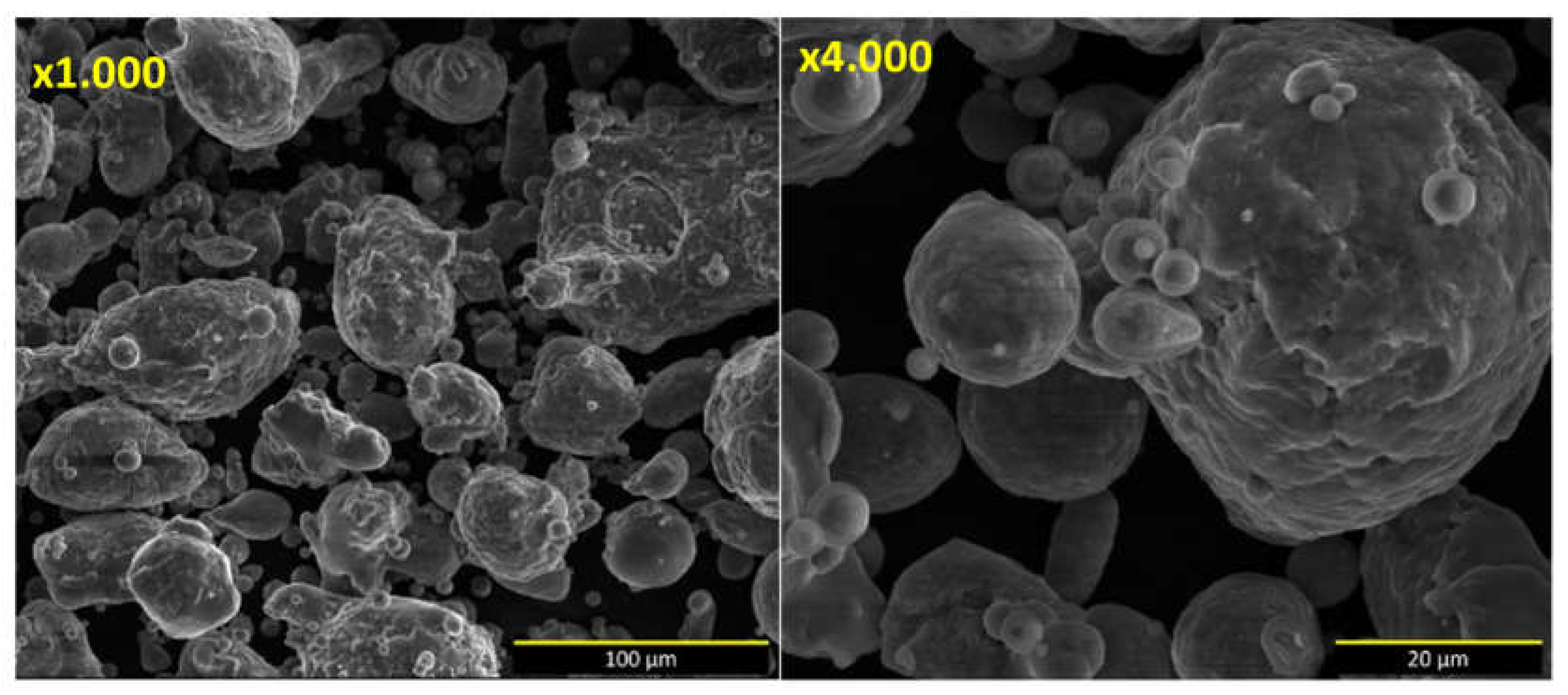
Figure 2.
Plasma projecting with the robot.
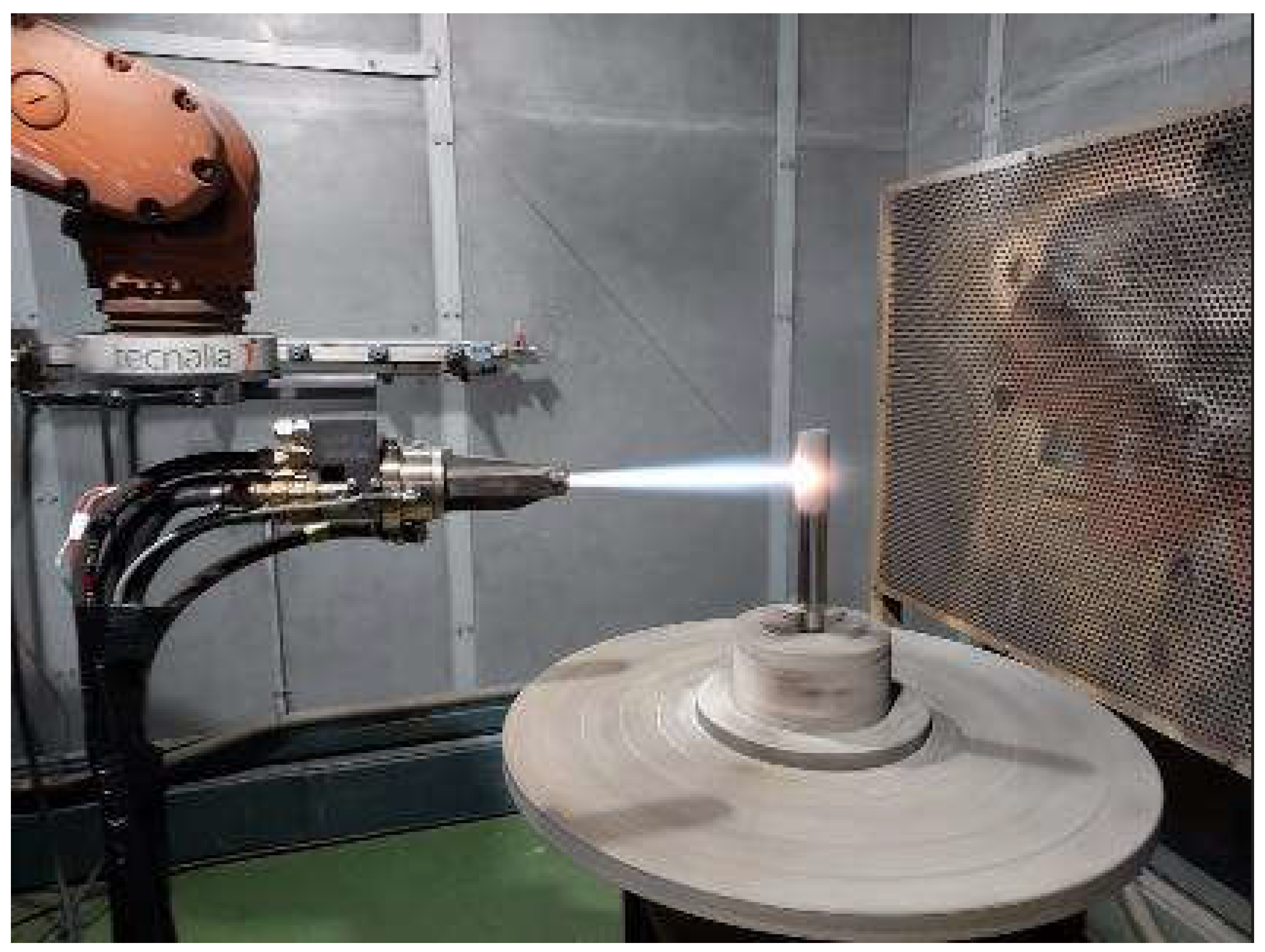
Figure 3.
SEM micrographics of the new multicomponent-based coating at the magnification of x1.000 and x2.000.
Figure 3.
SEM micrographics of the new multicomponent-based coating at the magnification of x1.000 and x2.000.
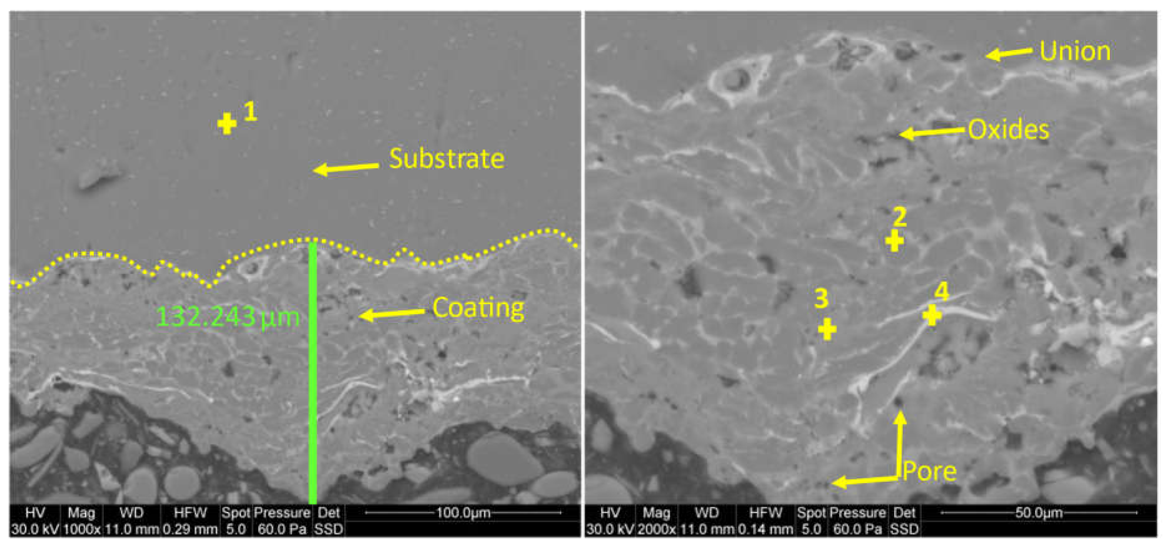
Figure 4.
Line scan EDS analysis showing the distribution of each element across the different alloys and interface.
Figure 4.
Line scan EDS analysis showing the distribution of each element across the different alloys and interface.

Figure 5.
EDS map of element distribution in the alloys and interface.
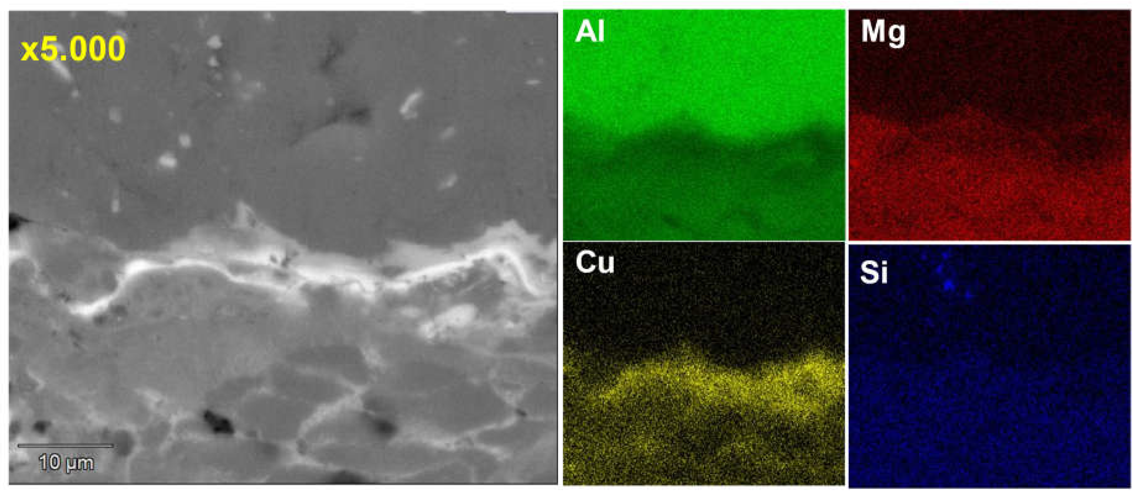
Figure 6.
OM image showing indentations of a sample at the magnification of x1.000 and hardness graph.
Figure 6.
OM image showing indentations of a sample at the magnification of x1.000 and hardness graph.
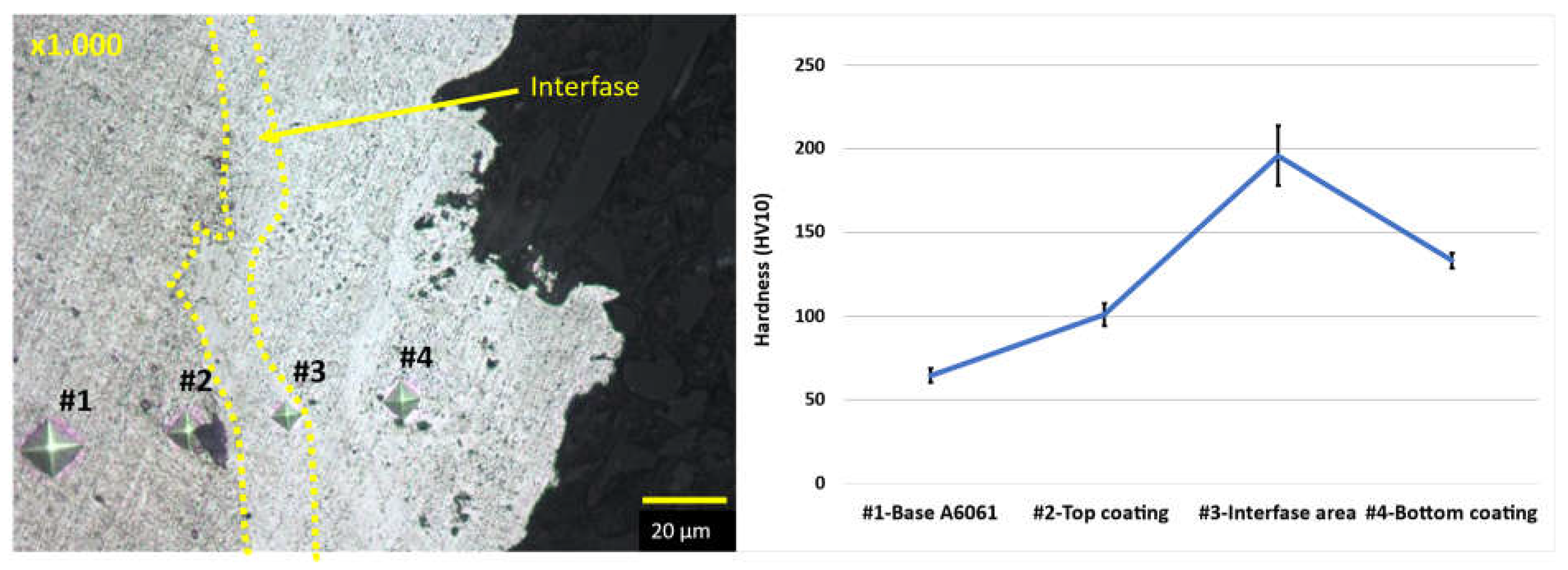
Figure 7.
Evolution of the coefficient of friction for the experimental alloys: A6061 with and without the coating, and multicomponent Al80Mg10SiCu5 in as-cast state.
Figure 7.
Evolution of the coefficient of friction for the experimental alloys: A6061 with and without the coating, and multicomponent Al80Mg10SiCu5 in as-cast state.
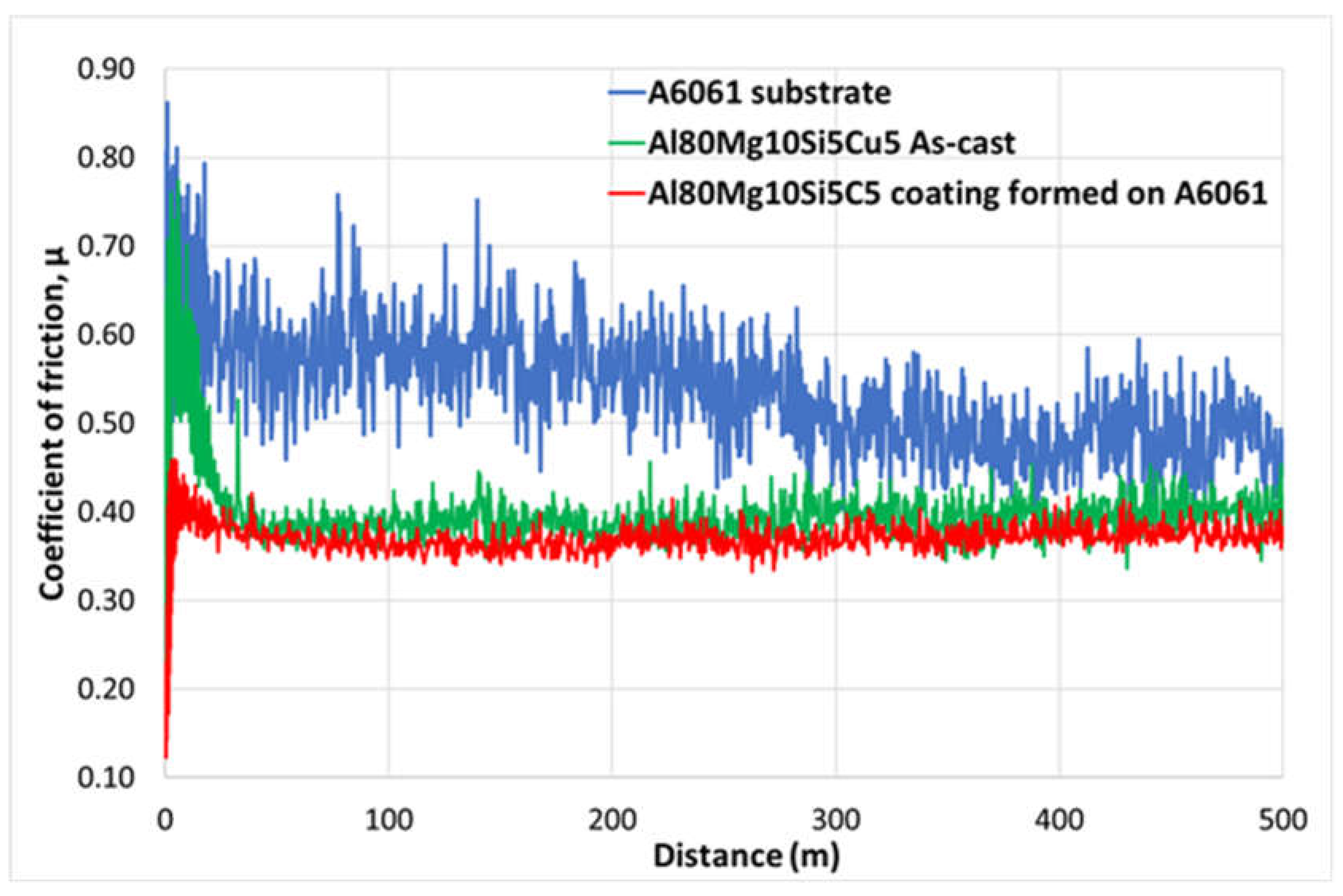
Figure 8.
Wearing surface topographies. a) 3D profile of A6061 with the coating, b) 3D profile of A6061 without the coating, c) 2D profile of A6061 with the coating, d) 2D profile of A6061 without the coating.
Figure 8.
Wearing surface topographies. a) 3D profile of A6061 with the coating, b) 3D profile of A6061 without the coating, c) 2D profile of A6061 with the coating, d) 2D profile of A6061 without the coating.
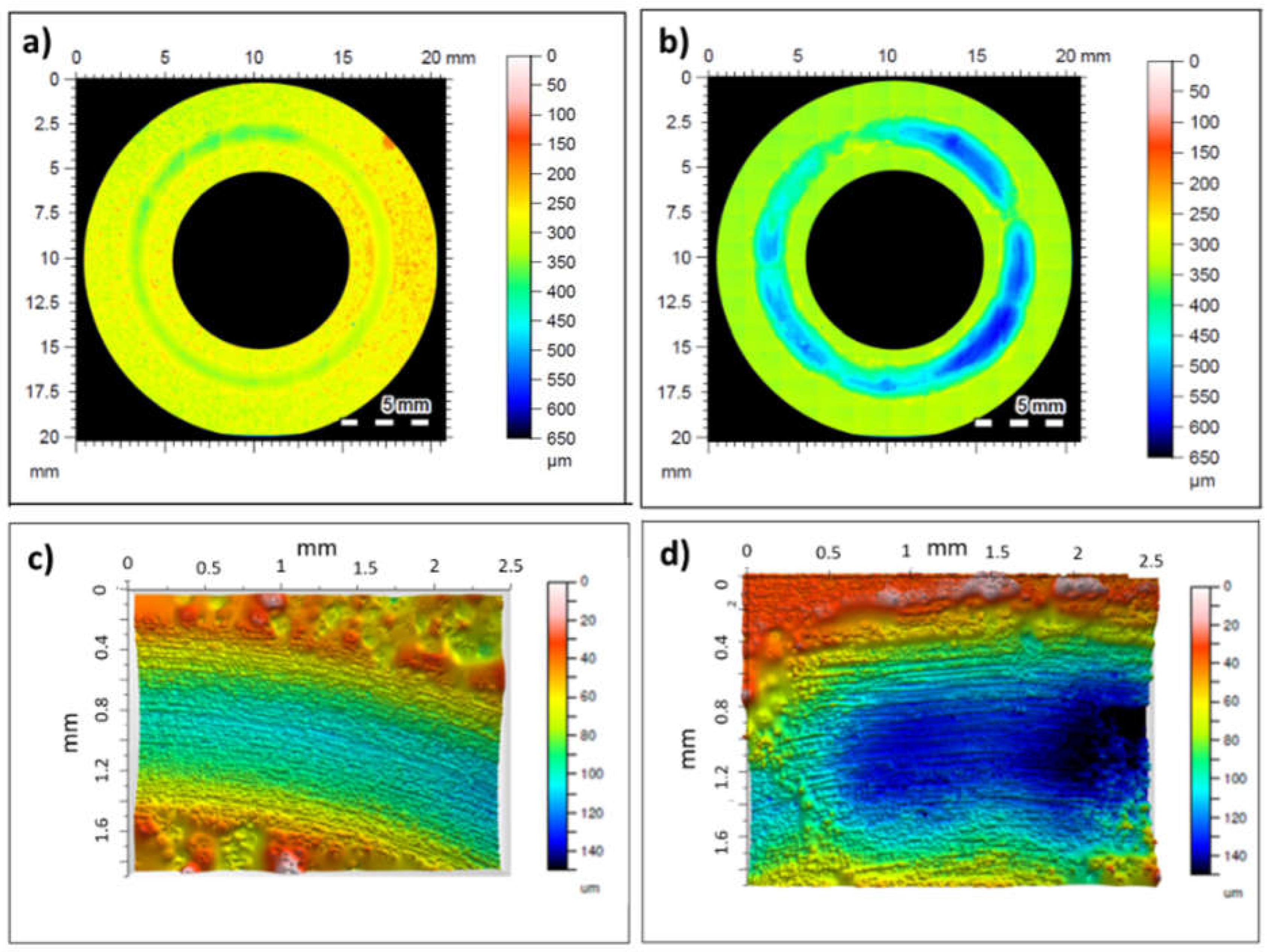
Figure 9.
Laser confocal imagen of wear track at low magnification a) A6061 with the coating, b) A6061 without the coating; at high magnification c) A6061 with the coating, d) A6061 without the coating.
Figure 9.
Laser confocal imagen of wear track at low magnification a) A6061 with the coating, b) A6061 without the coating; at high magnification c) A6061 with the coating, d) A6061 without the coating.
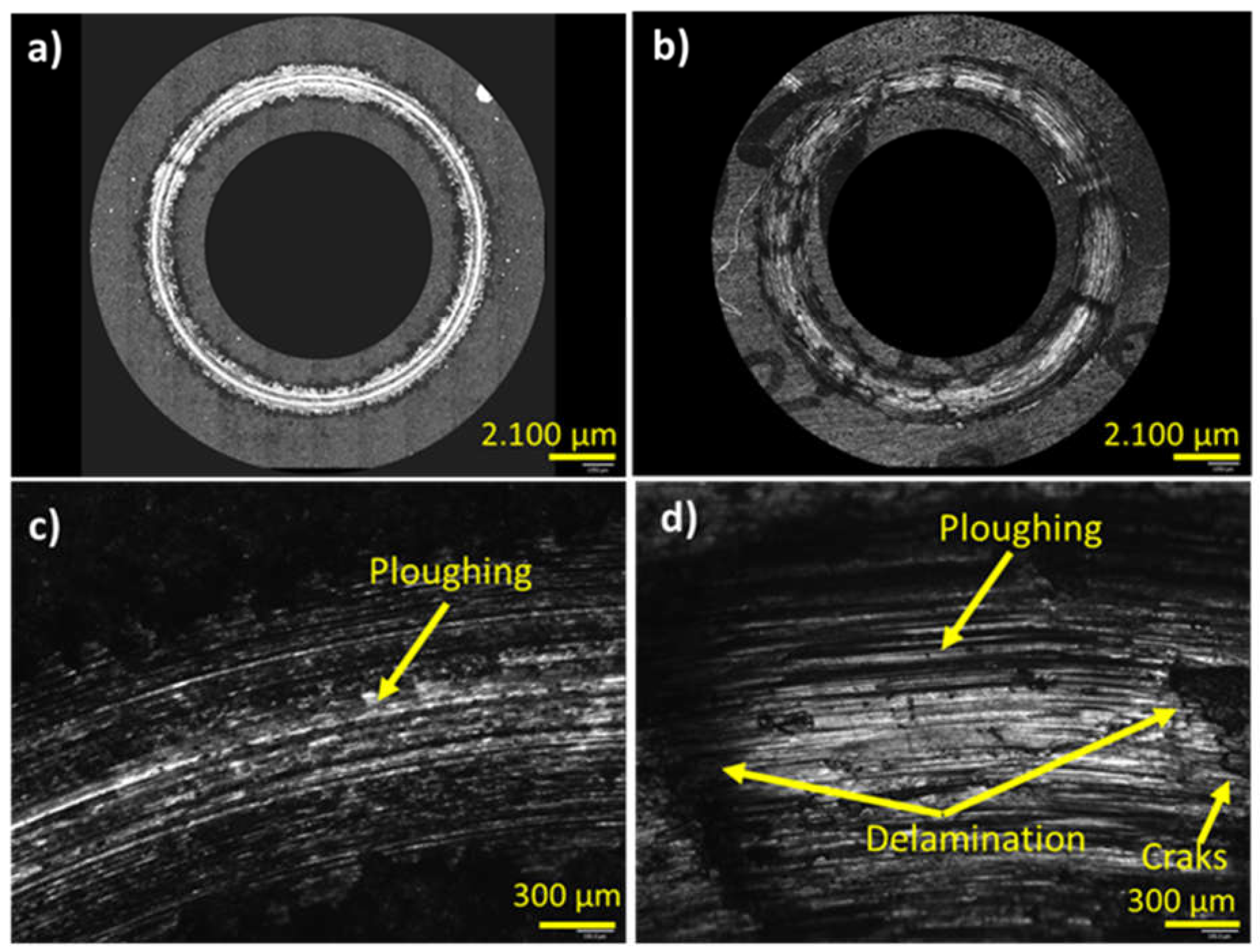
Figure 10.
Laser confocal imagen of the cross-sectional microstructure, a) A6061 with the coating at low magnification, c) at high magnification; b) A6061 without the coating at low magnification d) at high magnification.
Figure 10.
Laser confocal imagen of the cross-sectional microstructure, a) A6061 with the coating at low magnification, c) at high magnification; b) A6061 without the coating at low magnification d) at high magnification.
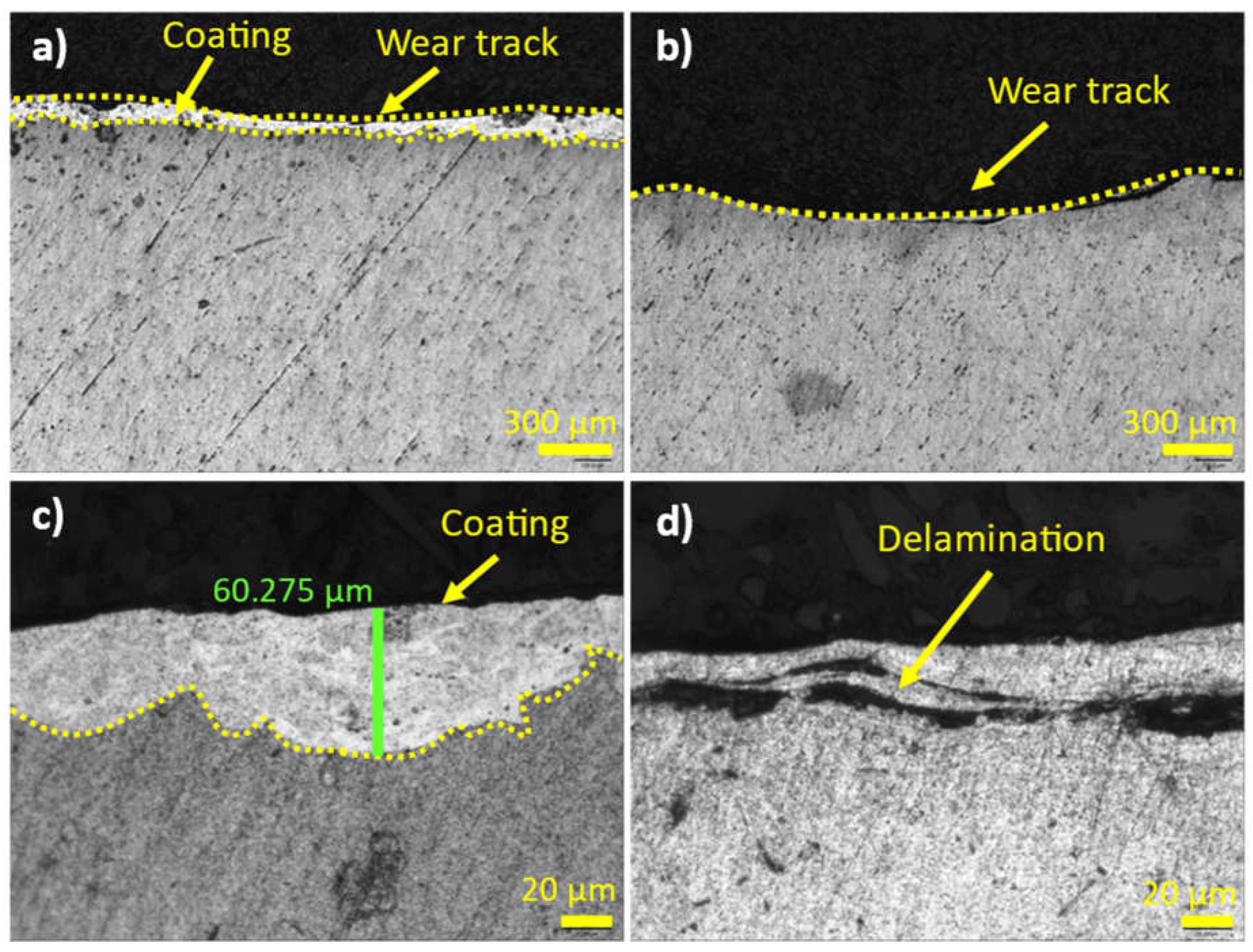
Figure 11.
Comparison of microstructures in the Al80Mg10Si5Cu5 multicomponent alloy at different cooling rates.
Figure 11.
Comparison of microstructures in the Al80Mg10Si5Cu5 multicomponent alloy at different cooling rates.
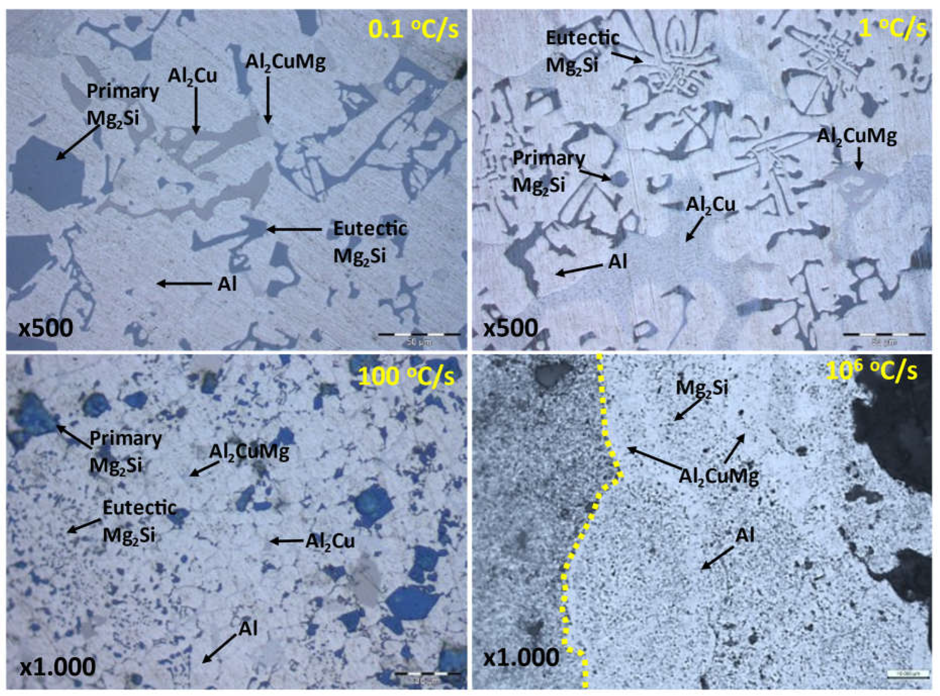
Figure 12.
Correlation of %IACS with solution components and cooling rates.
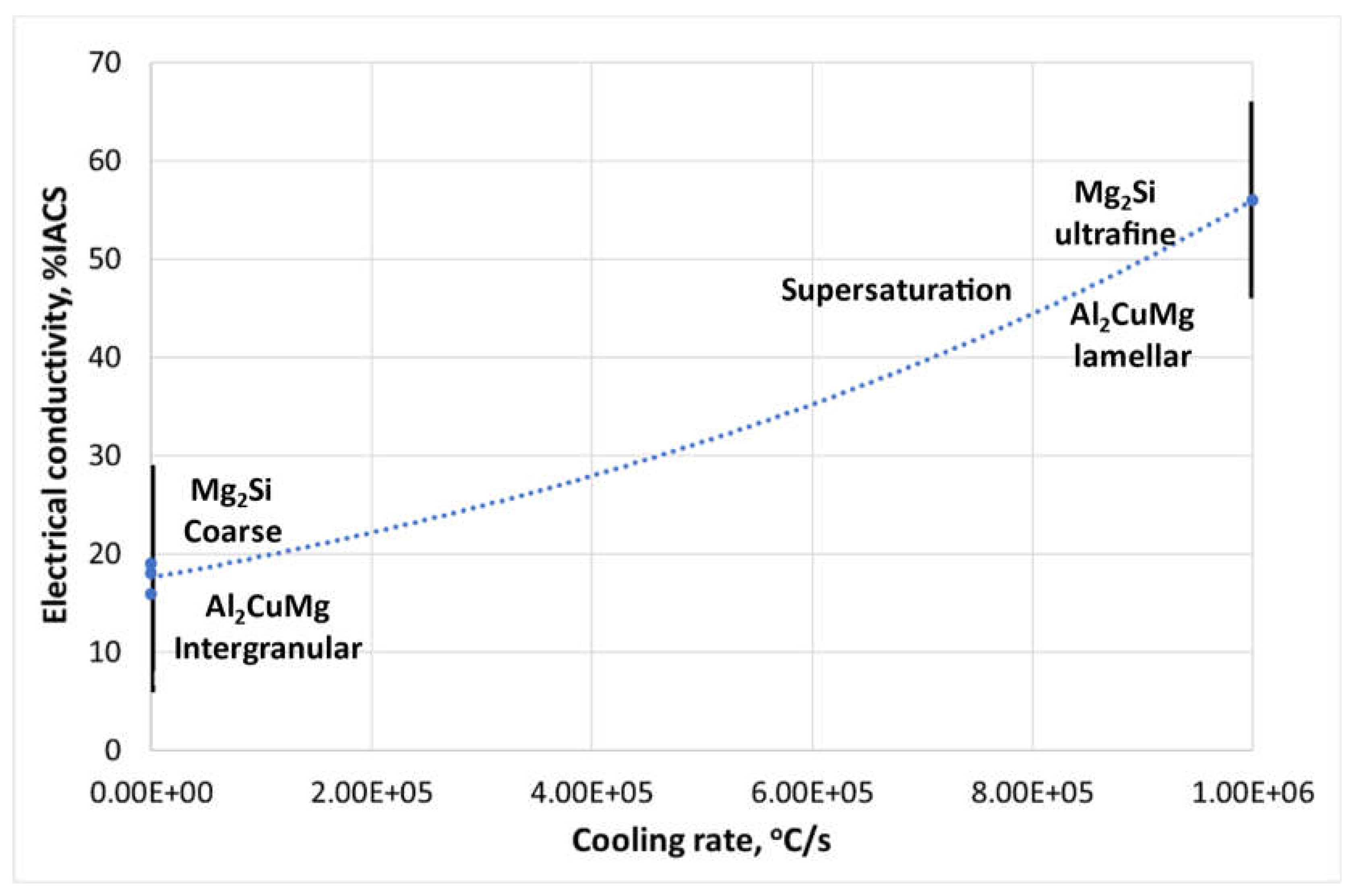

Table 1.
Chemical composition of experimental alloys in %wt.
| Alloy | Al | Mg | Si | Cu | Mn | Fe | Zn |
|---|---|---|---|---|---|---|---|
| Al80Mg10Si5Cu5 | 78.9 | 10.3 | 5.6 | 4.7 | 0.1 | 0.3 | 0.1 |
| A6061 | 98.2 | 0.9 | - | 0.9 | - | - | - |
Table 2.
Mechanical, electrical, and thermal properties of experimental alloys.
| Alloy | Hardness (HV3) | Electrical conductivity (%IACS) | Melting point (ºC) |
|---|---|---|---|
| Al80Mg10Si5Cu5 | 130 ± 13.01 | 17 ± 0.55 | 592 |
| A6061 | 68 ± 4.17 | 57 ± 0.41 | 585 |
Table 3.
Sliding wear test parameters.
| Test Parameters | Selected Value |
|---|---|
| Load (N) | 15.0 |
| Velocity (m/s) | 0.1 |
| Rotation speed (rpm) | 127.3 |
| Sliding distance (m) | 500.0 |
| Track diameter (mm) | 15 |
| Environment | Dry air |
Table 4.
Chemical composition (wt%) of new multicomponent-based coated material.
| Point | Al | Mg | Si | Cu | Mn | Fe |
|---|---|---|---|---|---|---|
| 1 | 97.14 | 1.0 | - | 1.30 | 0.6 | |
| 2 | 82.8 | 7.9 | 5.5 | 3.6 | 0.4 | |
| 3 | 78.6 | 8.1 | 5.9 | 6.8 | 0.2 | 0.5 |
| 4 | 68.9 | 6.5 | 4.8 | 25.4 | 0.4 |
Table 5.
Friction (µ) and Wear rate (K) coefficients.
| Sample | µ | K (mm3/N.m) |
|---|---|---|
| A6061 substrate | 0.52 ± 0.05 | 1.2 x 10 -3 ± 0.000223 |
| As-cast Al80Mg10Si5Cu5 | 0.40 ± 0.04 | 9.9 x 10 -4 ± 0.000191 |
| A6061 with the Al80Mg10Si5Cu5 coating | 0.40 ± 0.01 | 5.3 x 10 -4 ± 0.000019 |
Table 6.
Electrical conductivity (%IACS) of new coated A6061 alloy.
| Alloy | %IACS |
|---|---|
| A6061 with the Al80Mg10Si5Cu5 coating c | 56 ± 0.23 |
Table 7.
Results of corrosion of multicomponent Al80Mg10Si5Cu5 alloy, electrochemical impedance spectroscopy.
Table 7.
Results of corrosion of multicomponent Al80Mg10Si5Cu5 alloy, electrochemical impedance spectroscopy.
| OCP (V) | Rs (Ω) | Rc (Ω) | Rp (Ω) | Icor (µA/cm2) | Rcor (mm/year) |
|---|---|---|---|---|---|
| -0.874 | 7.9 | 6,909 | 31,890 | 0.681 | 0.007 |
Table 8.
Results of corrosion of multicomponent Al80Mg10Si5Cu5 alloy, potentiodynamic polarization in the TAFEL region.
Table 8.
Results of corrosion of multicomponent Al80Mg10Si5Cu5 alloy, potentiodynamic polarization in the TAFEL region.
| Ecor (V) | Rp (Ω) | Icor (µA/cm2) | Rcor (mm/year) |
|---|---|---|---|
| -0.743 | 154,600 | 0.118 | 0.001 |
Table 9.
Approx. Chemical composition (wt.%) of phases contained in Al80Mg10Si5Cu alloy.
| Phase | Gravity Sand | Gravity Die Cast | HPDC | Thermal spray |
|---|---|---|---|---|
| Primary Mg2Si | 32Mg, 33Al, 34Si, 1Cu | 34Mg, 31Al, 34Si, 1Cu | 30Mg, 42Al, 25Si, 3Cu | - |
| Eutectic Mg2Si | 27Mg, 42Al, 29Si, 1Cu | 28Mg, 41Al, 30Si, 1Cu | 17Mg, 67Al, 14Si, 3Cu | - |
| Aluminium | 93Al, 3Mg, 1Si, 2Cu | 93Al, 4Mg, 1Si, 2Cu | 88Al, 7Mg, 2Si, 3Cu | 84Al, 8Mg, 6Si, 3Cu |
| Al2Cu | 66Al, 34Cu | 66Al, 4Mg, 1Si, 29Cu | 66Al, 8Mg, 1Si, 24Cu | - |
| Al2CuMg | 80Al, 15Mg, 1Si, 10Cu | 75Al, 12Mg, 2Si, 11Cu | 76Al, 11Mg, 2Si, 12Cu | 76Al, 6Mg, 4Si, 15Cu |
Disclaimer/Publisher’s Note: The statements, opinions and data contained in all publications are solely those of the individual author(s) and contributor(s) and not of MDPI and/or the editor(s). MDPI and/or the editor(s) disclaim responsibility for any injury to people or property resulting from any ideas, methods, instructions or products referred to in the content. |
© 2024 by the authors. Licensee MDPI, Basel, Switzerland. This article is an open access article distributed under the terms and conditions of the Creative Commons Attribution (CC BY) license (http://creativecommons.org/licenses/by/4.0/).
Copyright: This open access article is published under a Creative Commons CC BY 4.0 license, which permit the free download, distribution, and reuse, provided that the author and preprint are cited in any reuse.


