
Submitted:
06 August 2024
Posted:
07 August 2024
You are already at the latest version
Abstract
The key question for the understanding of corrosion phenomena of Si3N4-SiC material in Al reduction cell – whether corrosion by gases (and oxidation in particular) opens way for the corrosion by molten cryolite, or corrosion of Si3N4-SiC by cryolite plays its own role in degradation of the material in service. More probably the reactions of silicon carbide and silicon nitride with molten cryolite go after the stage of pre oxidation to silicon dioxide.
The corrosion of Si3N4-SiC material in the reduction cell may take place by “gas-solid” reaction and by “liquid-solid” reaction.
There are several variants of lab corrosion test for the evaluation of corrosion resistance of Si3N4-SiC material to cryolite. The results of investigation of Si3N4-SiC lab corrosion test give no direct evidence of selective dissolution of specific phase (Si3N4 or SiC, α-Si3N4 or β-Si3N4) in cryolite. The existing variants of lab corrosion testing require clarification.
Keywords:
silicon carbide
; silicon nitride
; corrosion
; cryolite
; oxidation
; Al reduction cell
1. Introduction
Corrosion phenomena is very complex, and it is necessary to consider different processes and mechanisms of degradation. Corrosion of the refractories at high temperatures may proceed by gases, but of course it may proceed by liquids. The corrosion includes the process of chemical corrosion itself, but also it is necessary to consider the penetration of the aggressive liquid in open permeable pores, the diffusion of the aggressive melt (or constituents of the aggressive melts) into the structure of refractory materials, etc. The corrosion of Si3N4-SiC in Al reduction cell may be divided to corrosion by gases and corrosion by liquids.
In aluminum industry the main application of Si3N4-SiC material is side lining of aluminum reduction cells [1]. Si3N4-SiC side wall lining of reduction cells (Figure 1a,b) should withstand:
- -
- Chemical interaction with liquid electrolyte (consisting mainly of cryolite Na3AlF, enhanced by erosion of circulating metal and the electrolyte.
- -
- Oxidation of the upper part of side wall (above the bath) in complex oxidative-reduction atmosphere of CO/CO2 and vapors of fluorine and sodium compounds.
- -
- Erosion of circulating metal and electrolyte with particles of alumina.
Probably the key question for the understanding of corrosion phenomenon of Si3N4-SiC in all applications – whether corrosion by gases (and oxidation in particular) opens way for the corrosion by liquids, or corrosion of Si3N4-SiC by liquids plays its own role in the degradation of the material in service.
At the startup of the reduction cell or in case of overheating of the cell, Si3N4-SiC sidelining material is subjected to direct interaction with molten electrolyte (Figure 1a), however after 1,5-2 months Si3N4-SiC side lining in Al reduction cell is covered with side ledge – frozen electrolyte with alumina particles (Figure 1b).
Frozen side ledge (Figure 1b) to some extent protects Si3N4-SiC material from corrosion but is permeable to gases. The corrosion of Si3N4-SiC by O2, CO, CO2 in presence of volatile compounds of sodium and fluorine starts from the beginning of operation of the cell (when there is no side ledge), but continue during all service lifetime.
In real service the most severe corrosion of Si3N4-SiC takes place at the border of electrolyte and molten aluminum (Figure 1).
The quality of Si3N4-SiC materials is critical for the service lifetime of reduction cells, so lab testing is rather popular in Al industry. Al producers introduced sort of a “in-going control” of corrosion resistance of sidelining materials. Currently there are four kinds of laboratory corrosion testing of Si3N4-SiC materials for application in metallurgy of primary aluminum (Table 1): the test of SINTEF (Skybakmoen) [3,4], the test of Lacournet [5], the test of LIRR (Luoyang Institute of Refractory Research, China) [6,7,8] and the test of RUSAL [9].
SINTEF test models the behavior of Si3N4-SiC materials in the reduction cell, yet it doesn’t consider the partly reduction atmosphere above the melt and the change of the level of the cryolite in the service during the day. The test of Lacournet doesn’t take into account the procedure of electrolysis, but it considers the oxidation of Si3N4-SiC materials during long service. LIRR test adds the flow of CO2 to SINTEF test (models partly reducing atmosphere in reduction cell due to the burning of carbon anode), and RUSAL test considers the permanent change of the level of cryolite in the cell during the service.
The aim of the investigation is to generalize the results on corrosion and oxidation of Si3N4-SiC materials in the service from the smelters, compare the existing lab corrosion tests of Si3N4-SiC materials and to analyze the results of lab corrosion test according to RUSAL variant of testing [9].
2. Materials and Methods
Fabrication and properties of Si3N4-SiC materials, the analysis of properties, the analysis if structure and chemical composition are described elsewhere [10]
Laboratory corrosion resistance testing of Si3N4-SiC materials was performed in Engineering technological center of RUSAL (Krasnoyarsk, Russia) and in the laboratory of Voljsky Abrasive Plant (Carborundum Universal CUMI), Voljsky, Russia) according to methodic of RUSAL – the test specimen in form of the rods (Figure 2) 10*10*150 mm were dipped and taken out from the melt of cryolite with 10 minutes interval for 8 hours. The corrosion resistance was determined from the volume change of the samples after corrosion of rods (Figure 2).
The XRD and SEM analysis was performed in three zones - the zone above the melt, the zone of reaction and the zone below the melt.
During the lab testing Si3N4-SiC rods were moving up and down in the molten cryolite, so there was no strict border between Si3N4-SiC material, oxidized at air and Si3N4-SiC material, immersed in cryolite. The Si3N4-SiC rod during certain time was immersed in cryolite and during certain time was exposed to oxygen with vapors of sodium and fluorine compounds. Only small part of the rod remained in cryolite all the time.
3. Results
3.1. Corrosion and Oxidation of Si3N4-SiC Materials in Industrial Al Reduction Cells
Normally industrial reduction cells are under operation for 60-84 months, and during this time various changes may occur on macro level (Figure 3). Si3N4-SiC side lining may partly be dissolute on the border of electrolyte melt (Figure 3a), it may become thinner (Figure 3b), and sometimes (very rarely) it may crack (Figure 3c). The latter cases (Figure 3b,c) usually take place with material above the level of liquid electrolyte.
As a rule, the porosity of Si3N4-SiC side lining material diminishes (Table 2), especially in the upper part of lining, where the material has no contact with molten cryolite. Only industrial test may give an answer, in what material the porosity will diminish quicker. Lower porosity may have positive effect, because the area of possible reactions diminishes. However, in case of lower porosity the thermal strains may become bigger, that may cause cracking.
In Si3N4-SiC materials before service coarse grains of silicon carbide are surrounded by small grains of silicon nitride, the crystals have strict shapes, especially in relatively big α-SiC grains (Figure 4a). It is considered that α-silicon nitride crystallizes in the form of needle like grains, while β-silicon nitride crystals are more uniform in length and width.
At oxidation in the upper part of the side lining in Al reduction cell (the structure of material #2, Table 3) silicon nitride crystals loose their crystal shapes and become more rounded (Figure 4b), silicon oxide appears on lumpy silicon carbide crystals.
In course of the interaction of silicon nitride (the microstructure of material #3, Table 3) with molten cryolite silicon nitride crystals disappear, and silicon carbide crystals are becoming smooth and round shaped (Figure 4c).
In the pioneer papers on application of Si3N4-SiC materials in reduction cells [12,13,14] Jorge, Marquin and Temme took a generalized picture of the growth of silica content in Si3N4-SiC with time, not giving details and values of time and concentrations. According to them, after some short period the silica content in SiC side lining reaches 7-8 wt.% and remains permanent for a certain time.
The exact data on Silica content is Si3N4-SiC side lining in industrial reduction cells is limited (due to the high cost of industrial cell). Our data, collected at different Al smelters, show on sufficient silica content (Table 3), varying from 1,65% to 7-11 %.
3.2. Corrosion and Oxidation of Si3N4-SiC Materials at Laboratory Corrosion Testing
It is well known that in different zones Si3N4-SiC material is exposed to different kinds of chemical attack. According to the current research the specimen after in testing were analyzed in the three zones (to the extent, that was possible to do on small rods). The investigated zones were the zone above the cryolite melt, rather broad zone (because the specimen was moving up and down) of the “triple point” – the contact of the material, air and cryolite and in the zone, remained in the cryolite melt. The most intensive corrosion (and the volume loss) was in the zone of the “triple point”.
During the lab testing Si3N4-SiC rods were moving up and down in the molten cryolite, so there was no strict border between Si3N4-SiC material, oxidized at air and Si3N4-SiC material, immersed in cryolite. The Si3N4-SiC material during certain time was immersed in cryolite and during certain time was exposed to oxygen with vapors of sodium and fluorine compounds.
In our research in the zone above the level of cryolite (partly reducing atmosphere, the influence of the vapors of sodium and fluorine compounds) silicon carbide concentration diminishes more quickly, than silicon nitride concentration. It looks like that disappearing silicon carbide gives free silicon (Table 3). Yet the open porosity of the specimen after 8 hours exposure above the melt of cryolite in partly reducing atmosphere (with the vapors of fluorine and sodium compounds) reduces from 12,3% to 9,2%. In the zone above the melt the ratio of α/β modifications of silicon nitride remains approximately the same.
In the corrosion zone the silicon carbide content remains the same, the total silicon nitride content diminishes from 15,2% to 12,1%, while α-silicon nitride content decreases from 10,1% to 3,1%. This behavior is very close to what is described in the literature [8,9,10]. It is rather unexpected, that silicon oxynitride content grows from 3 % to 6,3%.
In the zone below the level of cryolite silicon carbide is also less corrosion resistant comparing to silicon nitride, but here it transforms to silicon oxide. In the zone below the melt the ratio of α/β modifications of silicon nitride remains approximately the same, as in starting material. Open porosity of the specimen after 8 hours exposure below the melt of cryolite reduces from 12,3% to 4,7 %.
4. Discussion
4.1. On Corrosion and Oxidation of Si3N4-SiC Materials in Al Reduction Cell and at Lab Testing
According to Wang and Skybakmoen [15,16], thermodynamically the potential for Silicon Nitride and Silicon Carbide to react directly with liquid cryolite Na3AlF6 is minimal due to the positive Gibbs free energies of reactions (ΔG = + 500 kJ/mole).
However we know perfectly well, that the corrosion process occur in SiC-S3N4 refractories of side lining in Al reduction cell (Figure 3 a), that may take place due to complex reactions, mainly due to pre-oxidation.
The reactions of silicon carbide and silicon nitride in the reduction cell may take place with gaseous substances and liquid substances. The major part of oxidation reactions [2] proceeds with positive volume effect. The reaction products occupy more space, than the reactants.
Usually, the temperatures 800-900oC (that are normal in side lining) are not considered to be critical for oxidation of silicon carbide and silicon nitride. However, everything changes in presence of fluorine compounds and vapors of alkali compounds. The change of the mechanism from passive oxidation with appearing silica protective film to active oxidation, where gaseous reaction products are removed from reaction zone, takes place in presence of these compounds.
The picture with the specimen from lab reduction cell is a little bit different. In the zone above the melt of cryolite the content of silicon nitride remains almost unchanged (Table 4), there is a little growth of silicon oxynitride content, but there appears 5% of free silicon. The amount of silicon carbide decreases from 81,6% to 73,3%, so formal analysis of lab corrosion experiment suggests, that in partly reducing atmosphere above the melt of cryolite, silicon nitride content remains unchanged while silicon carbide may reduce to free silicon and carbon oxide.
In the corrosion zone at lab corrosion test (Table 4), where the material is exposed to cryolite and gases, there is almost no changes in concentrations of silicon carbide, the content of silicon oxynitride increases considerably, there is no traces of silicon oxide (probably it dissolves in cryolite). In the corrosion zone the content of α-silicon nitride decreases three times (comparing with initial material). The microstructures of this zone are on Figure 5c. Some small needlelike crystals (that may be attributed to α-Si3N4) are seen on crystals of silicon carbide.
In the zone below cryolite the content of silicon nitride and silicon oxynitride remains almost the same, the same may be said about the ratio of α/β modifications of silicon nitride. According to XRD analysis silicon carbide oxidizes to silicon oxide. Probably this takes place in the pores of Si3N4-SiC material (in case without the penetration of cryolite in the pores)
So, the general considerations suggest that more probable mechanism of the decay of Si3N4-SiC side lining is partial pre oxidation with following interaction of appearing silica with components or electrolyte in gas phase or in liquid phase, with following evaporation or dissolution. However, the picture is complex and needs future investigations.
4.2. On Priority of Corrosion Resistance of Silicon Carbide over Silicon Nitride and of α-Silicon Nitride over β-Silicon Nitride
In the literature it is mentioned [17,18,19], that the silicon nitride phase is less corrosion resistant to the cryolite melt compared to silicon carbide phase. There are also suggestions, that α- modification of silicon nitride is less corrosive resistant to cryolite melt comparing with β-modification. These assumptions are made according to microstructure analysis of Si3N4-SiC material after contact with liquid electrolyte. According to profound investigations of Skybakmoen [15,16], performed on a big number of samples, α- modification of silicon nitride is less corrosion resistant to cryolite, comparing with β-modification. The conclusions are made by analysis of microstructure of corroded zone after lab corrosion tests.
According to the current research in lab testing there is no direct indication of the influence of modifications on the bulk volume loss of Si3N4-SiC materials, yet according to SEM and XRD α-Si3N4 dissolves a little bit quicker, and Silicon Nitride disappears more quickly also in the corrosion zone itself. In our research in the zone above the level of cryolite (partly reducing atmosphere, the influence of the vapors of sodium and fluorine compounds) silicon carbide concentration diminishes more quickly, than silicon nitride concentration. It looks like that disappearing silicon carbide gives free silicon (Table 4). In the zone above the melt the ratio of α/β modifications of silicon nitride remains approximately the same.
In the zone below the level of cryolite silicon carbide is also less corrosion resistant comparing to silicon nitride, but here it transforms to silicon oxide. In the zone below the melt the ratio of α/β modifications of silicon nitride remains approximately the same, as in starting material.
There are 4 known kinds of lab corrosion testing of Si3N4-SiC material [4,5,6,7,8,9] to molten cryolite (and aluminium). The criterion of testing is the volume change of the tested samples due to dissolution. Yet is well known that in different zones Si3N4-SiC material is exposed to different kinds of chemical attack.
In current research there was an attempt to investigate the zones of Si3N4-SiC material after lab corrosion test. It looks like more profound research is required for the clarification of testing of Si3N4-SiC materials.
5. Conclusions
- More probably the reactions of Silicon Carbide and Silicon Nitride with molten cryolite proceed via the stage of pre oxidation. The corrosion of Si3N4-SiC materials in Aluminium reduction cell may proceed due to the reactions with gases and with liquid substances. A major part of the oxidation reactions of Silicon Carbide and Silicon Nitride proceed with positive volume effect.
- In current research the results of chemical and phase analysis of Si3N4-SiC materials after lab corrosion test to molten cryolite in the zones differ (above the level of molten cryolite, in the zone of the level of the melt and below the level of the melt of cryolite).
- There is no direct indication of the influence of silicon nitride modifications on the bulk volume loss in Si3N4-SiC materials, yet according to SEM and XRD α-Si3N4 in the zone of reaction (maximal exposure) dissolves a little bit quicker, than β-Si3N4 and that silicon nitride disappears in course of chemical interactions a little bit more quickly than silicon carbide.
Acknowledgments
Author is grateful to Mrs. Oksana Danilova (Voljsky abrasive plant, Carborundum Universal) for the support, comments and fruitful discussions, acknowledgements to smelters for comments and informational support, the warmest gratitude to Dr. Aleksandr Proshkin, Andrey Sbitnev and Elena Marakushina from Engineering Technical Center, RUSAL, Krasnoyarsk for support in corrosion testing and consultations. SEM investigations were made on equipment of the Center for collective use of Russian Mendeleev University of chemical technology. This research did not receive any specific grant from funding agencies in the public, commercial, or not-for-profit sectors. The author declare that he has no conflict of interest.
References
- M. Sørlie, H. Øye, Cathodes in Aluminium Electrolysis, 3-d edition, Aluminium-Verlag, 2010, 662 p.
- Andrey Yurkov, Refractories for Aluminium: Electrolysis and the Cast House, 2015, Springer International Publishing AG, 254 p., ISBN 978-3-319-11442-2.
- E. Skybakmoen, H. Gudbransen and L.T. Stoen, “Chemical Resistance of Sidelining materials based on SiC and Carbon in Cryolitic melts – a laboratory study”, Light Metals, 128 (1999), 215-222.
- E. Skybakmoen, L. Stoen, J. H. Kvello and O. Darrel, “Quality evaluation in Nitride bonded Silicon Carbide Sidelining Materials”, Light Metals, 134 (2005), 773-778.
- R. Laucournet, V. Laurent, Didier Lombard, Chemical resistance of sidelining refractory based on Si3N4 bonded SiC, Light Metals, 2008, p. 961-966.
- J. Zhao, Z. Zhang, W. Wang, G. Liu, “Test method for Resistance of SiC material to Cryolite”, Light Metals, 2006, pp 663-666.
- B.L. Gao, Z.W. Wang and Z.X. Qiu, “Corrosion Tests and Electrical Resistivity Measurement of SiC-Si3N4 Refractory Materials”, Light Metals 2004, pp 419-424.
- C. Cao, B. Gao, Z. Wang, X. Hu, Z. Qui, “A new test method for evaluating Si3N4-SiC bricks corrosion resistance to aluminium electrolyte and oxygen”, Light Metals 2006, pp 659-661.
- A. Proshkin, V. Pingin, P. Polyakov et ali, Study of the state and dynamics of Wear of the side lining in the cathods of Aluminium Cells, J. Siberian Federal University. Engineering and technologies, 2, 2013 6, pp. 276-284.
- Andrey L. Yurkov, Silicon Carbide–Silicon Nitride Refractory Materials: Part 1 Materials Science and Processing, July 2023, Processes 11(7), 2134. [CrossRef]
- Proshkin A.V., Pingin V.V., Polyakov P.V.,et ali, Analysis of decay of side lining in cathodes for aluminium reduction cells, Journal of Siberial Federal university, Engineering and technology, 3, 2013, pp. 276-284.
- J. Schoenhahl, E.Jorge, O. Marguin, S. Kubiak, P. Temme, Optimization of Si3N4 bonded SiC refractories for aluminium reduction cells, Light Metals, 2001, p. 251-255.
- Jorge E. and Marguin O. Si3N4 Bonded SiC Refractories for Higher Aluminium Cell Performance, Aluminium Times. - September 2004.- p. 47-50.
- Jorge E., Marguin O. and P. Temme, The usage of N-SiC refractories for the increasing of productivity of aluminium reduction cells, Aluminium of Siberia, v.9, 2003, Krasnoyarsk, p. 203-208.
- Zh. Wang, E. Skybakmoen, T. Grande, Spent Si3N4 Bonded Sidelining Materials in Aluminium Electrolysis Cells, Light Metals, 2009, pp.353-358.
- E. Skybakmoen, T. Grande, Zh. Wang, The influence of microstructure of Si3N4-SiC side-lining materials on chemical /oxidation resistance behavior tasted in laboratory scale, Proceedings of 11th Australasian Aluminium Smelting Technology Conference, Dubai, UAE, 6-11 December 2014, Editors: Barry Welch, Maria Scillos-Kazakos, UNSW, Australia, IBSN 978-0-7334-3518-8, 23W3.
- R. Etzion, J.B. Metson, “Factors Affecting Corrosion Resistance of Silicon Nitride Bonded Silicon Carbide Refractory Blocks”, Journal of the American Ceramic Society, 95 (2012), 410–415. [CrossRef]
- J. Metson, G. McIntoch, R. Etzion, Materials science constraints on the development of Aluminium Reduction Cells, Advanced Materials Development and Performance (AMDP2011), Int. J. of Modern physics: Conference Series, V.6 (2012), p. 25-30.
- R. Paulek, “SiC in Electrolysis Pots: An Update”, Light Metals, 135 (2006), pp.655-658.
Figure 1.
Typical construction of Al reduction cell: (a) cell without frozen side ledge, 1 – upper part of SiC side lining above the level of electrolyte, 2 – the border between electrolyte and molten aluminum; (b) cell with normal side ledge [2].
Figure 1.
Typical construction of Al reduction cell: (a) cell without frozen side ledge, 1 – upper part of SiC side lining above the level of electrolyte, 2 – the border between electrolyte and molten aluminum; (b) cell with normal side ledge [2].
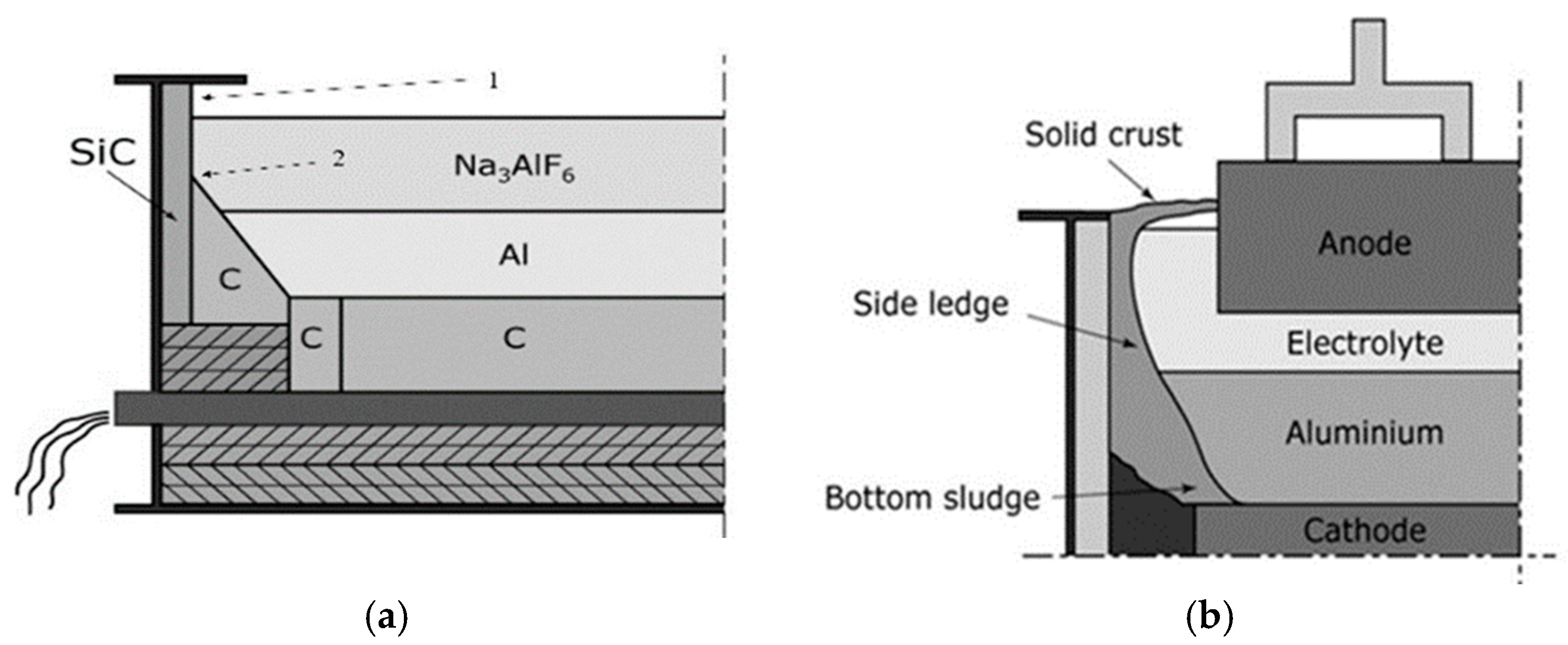
Figure 2.
Si3N4-SiC rods: a) before lab corrosion testing; b) Si3N4-SiC rod after testing, degree of corrosion -2; c) part of Si3N4-SiC rod after testing, degree of corrosion -7.
Figure 2.
Si3N4-SiC rods: a) before lab corrosion testing; b) Si3N4-SiC rod after testing, degree of corrosion -2; c) part of Si3N4-SiC rod after testing, degree of corrosion -7.
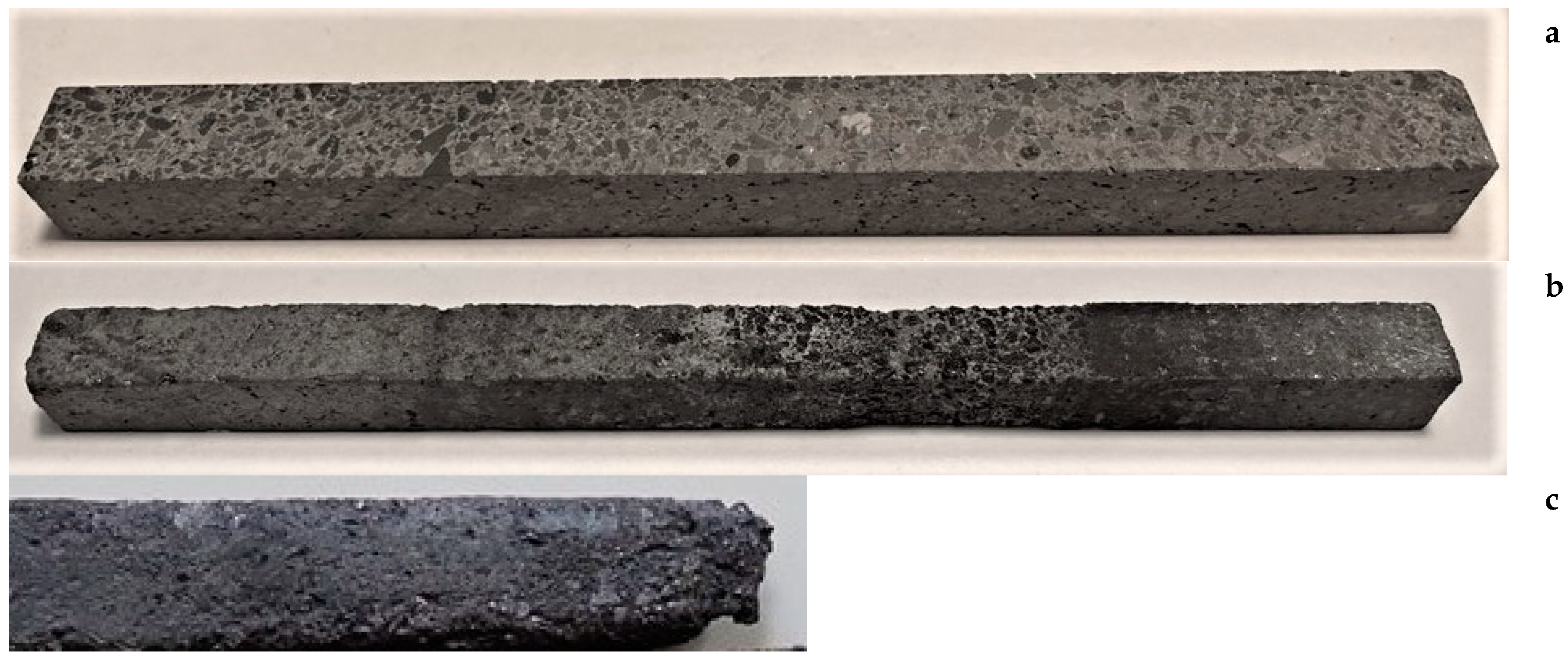
Figure 3.
Si3N4-SiC sidelining materials after service in Al reduction cells: a) side lining after 60 months of service in reduction cell; b) groove in the upper part of side lining after the service in the reduction cell for 45 months; c) cracking and spalling of side lining in the upper part after the service in the reduction cell for 24 months [2].
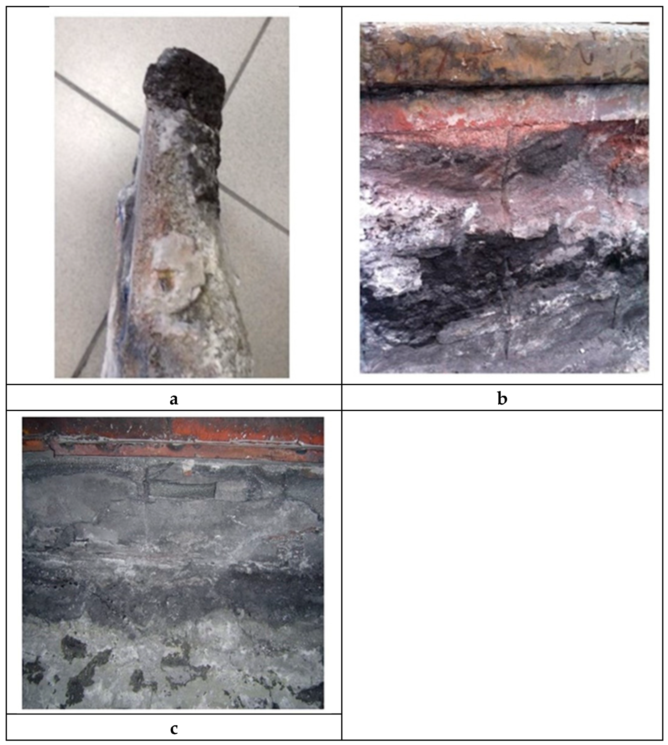
Figure 4.
Microstructures of Si3N4-SiC materials: a) before the service (as received); b) the upper part of Si3N4-SiC block after the service in Al reduction cell for 20 months (Figure 3b); c) the lower part of Si3N4-SiC block after the service in Al reduction cell for 60 months (Figure 3a) [2].
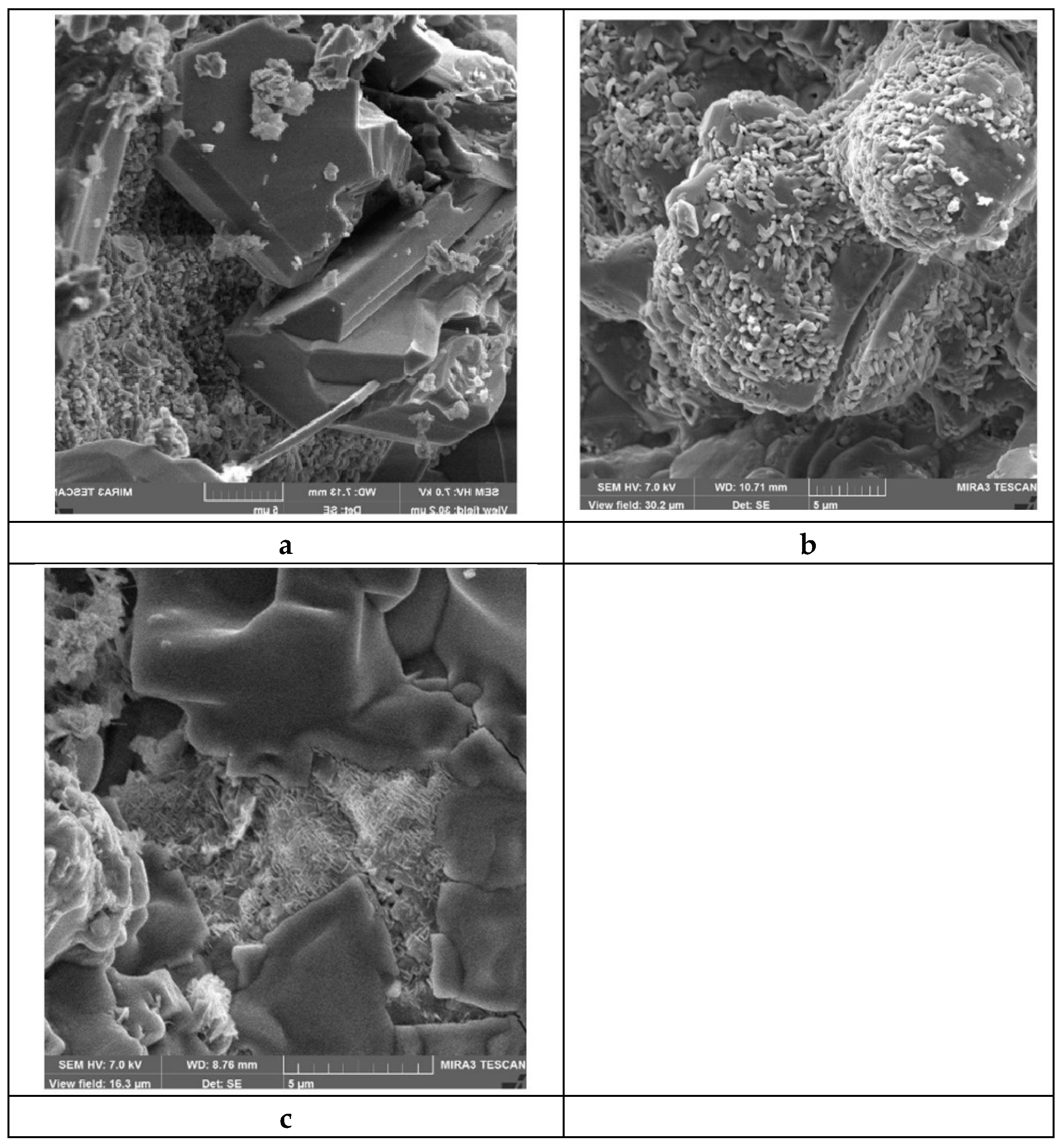
Figure 5.
Microstructures of Si3N4-SiC rods after lab corrosion test: a) the zone above the melt after the test; b) the “triple point”; c) – zone under cryolite.
Figure 5.
Microstructures of Si3N4-SiC rods after lab corrosion test: a) the zone above the melt after the test; b) the “triple point”; c) – zone under cryolite.
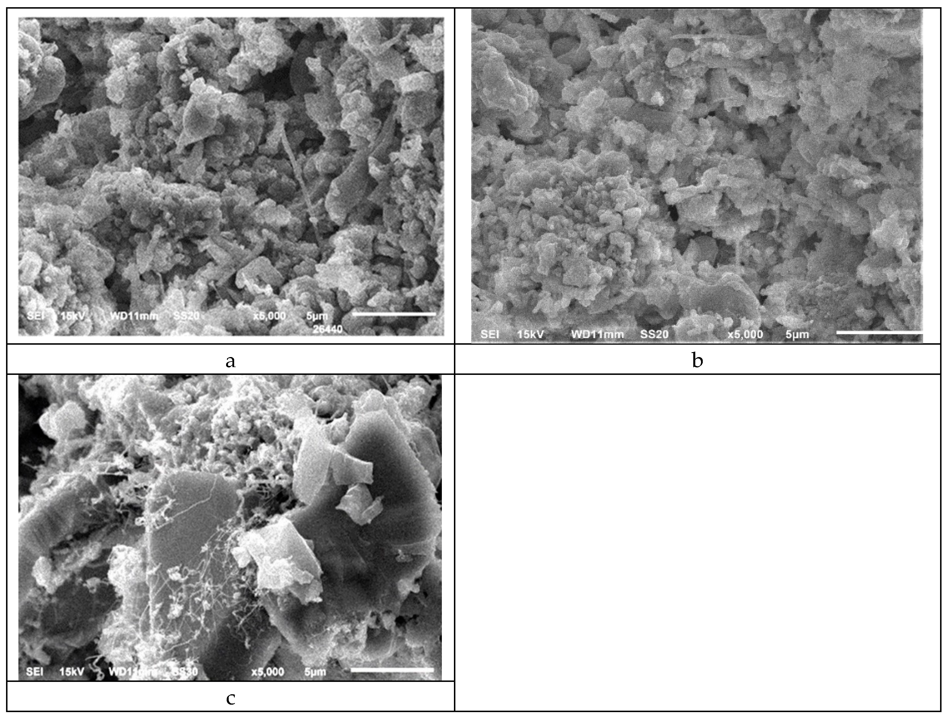

Table 1.
Conditions of lab corrosion tests of Si3N4-SiC material to molten cryolite.
| Test | electrolysis | Pre oxidation | atmosphere | Movement of specimen rods |
| SINTEF Skybakmoen [3,4] | yes | no | Air. Some vapors (mainly NaAIF4) and C02/ CO from the burning anode. | No. |
| Lacournet [5] | no | yes | air. Some vapors (mainly NaAIF4) | No |
| LIRR [6,7,8] | yes | no | Some vapors (mainly NaAIF4). CO2 flow | Yes. Rotation of rods |
| RUSAL Proshkin [9] | no | no | Some vapors (mainly NaAIF4). Air | Yes. Specimen rods are dipped in the cryolite and taken out |
Table 2.
The change of porosity and the density of Si3N4-SiC side lining of different producers (1 and 2) at service in the reduction cells.
Table 2.
The change of porosity and the density of Si3N4-SiC side lining of different producers (1 and 2) at service in the reduction cells.
| No | Apparent density (initial), g/sm3 | Apparent density (after 180 days), g/sm3 | Open porosity (initial), % | Open porosity (after 180 days), % |
|---|---|---|---|---|
| 1 | 2,68 | 2,75 | 15,8 | 10,4 |
| 2 | 2,68 | 2.77 | 15,6 | 7,5 |
Table 3.
Chemical composition of Si3N4-SiC materials after service in reduction cells - current research (#2-5) and according to [11] (#1).
Table 3.
Chemical composition of Si3N4-SiC materials after service in reduction cells - current research (#2-5) and according to [11] (#1).
| Composition, mass.% | Service time, months | comments | |||||
|---|---|---|---|---|---|---|---|
| SiC | Si3N4 | SiO2 | Si | Oxides, including Na2SiO3 | |||
| 1 [11] | 50,7 | 16,62 | 11,1 | - | 21,58 | 46 | - |
| 2 | 73,1 | 15,4 | 7,3 | - | 2,2 | 39 | Upper part |
| 3 | 68,1 | 18,2 | 7,2 | - | 6,5 | 39 | Lower part |
| 4 | 73,7 | 23,3 | 1,65 | 0,34 | 0,98 | 36 | Upper part |
| 5 | 71 | 25,3 | 2,3 | 0,3 | 1,1 | 36 | Lower part |
Table 4.
The composition of Si3N4-SiC materials before and after lab corrosion test according to XRD.
Table 4.
The composition of Si3N4-SiC materials before and after lab corrosion test according to XRD.
| SiC, % | β-Si3N4, % | α-Si3N4, % | α/β | Σ Si3N4, % | Si3N4/SiC | Si2ON2, % | Si, % | SiO2, % | |
| before corrosion test | 81,6 | 5 | 10,1 | 2,02 | 15,1 | 0,185 | 3 | 0,3 | - |
| after corrosion test | |||||||||
| upper part | 73,3 | 6,7 | 10,5 | 1,57 | 17,2 | 0,23 | 4,5 | 5 | - |
| corrosion zone | 81,6 | 9 | 3,1 | 0,34 | 12,1 | 0,148 | 6,3 | - | - |
| lower part, dipped in cryolite | 76,3 | 6,7 | 11,1 | 1,66 | 17,8 | 0,23 | 3,5 | - | 2,4 |
Disclaimer/Publisher’s Note: The statements, opinions and data contained in all publications are solely those of the individual author(s) and contributor(s) and not of MDPI and/or the editor(s). MDPI and/or the editor(s) disclaim responsibility for any injury to people or property resulting from any ideas, methods, instructions or products referred to in the content. |
© 2024 by the authors. Licensee MDPI, Basel, Switzerland. This article is an open access article distributed under the terms and conditions of the Creative Commons Attribution (CC BY) license (http://creativecommons.org/licenses/by/4.0/).
Copyright: This open access article is published under a Creative Commons CC BY 4.0 license, which permit the free download, distribution, and reuse, provided that the author and preprint are cited in any reuse.


