Presenting the idea of quantum fluid processing, and describing the mult-mode piston as a way to implement it.
3.3. Multi-Mode Piston
What is the simplest way to move fluid in a given direction? A piston fitted in the container, a capsule, with. a degree of freedom to move back and forth along a given direction, say the longest dimension. Now we need to take care of movement in the other two directions. It takes a small spark to suggest drilling holes in the piston and allowing each hole to be either covered (closed) or uncovered (open). Moving a holes-drilled piston in a closed container will impress momentum on the fluid in the direction of the drilled holes. If a hole is built in an inclined direction towards the direction of movement of the piston then when the piston moves while the hole is open, then it forces fluid to flow through the hole in the inclined direction, which is off the main direction handled by the piston. Now if we add to this piston with holes the freedom to rotate around the main direction of piston movement then we achieve the ability to generate planned flow in all three directions. If the piston does not rotate and large holes are open then the movement of the piston will generate a laminar flow. If on the other hand the piston will rotate and fast, and some holes are open, while the rest are closed, then a movement back and forth of the rotating piston will generate a turbulent flow.
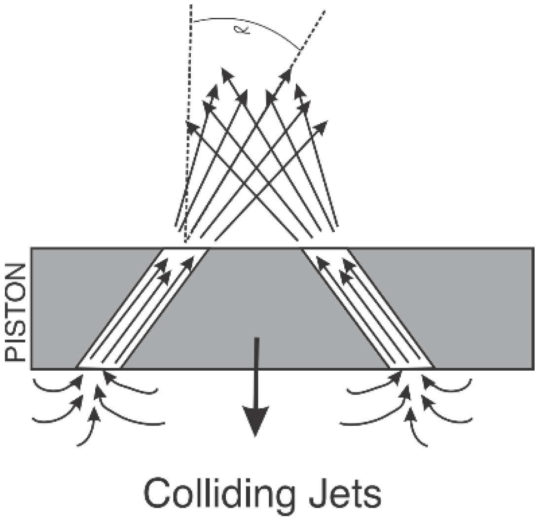
The figure below depicts how two streams emerging from cross inclined holes in the piston are getting thoroughly mixed:
Figure 3.
Colliding Jets.
Figure 3.
Colliding Jets.
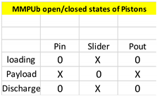
The table below describes the open/closed states ("O"-open, "X" - closed) of the holes in Pin, and Pout the two stationary pistons (edges) of the capsule and the slider piston for the multi-mode piston (MMP) unit basic version:
Table 1.
MMPub open/closed States of Pistons
Table 1.
MMPub open/closed States of Pistons
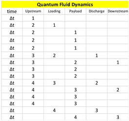
The quantum fluid dynamics is shown relative to four successive quanta of fluids:
Table 2.
Quantum Fluid Dynamics.
Table 2.
Quantum Fluid Dynamics.
In summary, a rotating piston drilled with fluid pass way holes, while moving from one edge of the capsule to the other, will create any desired flow pattern in the captured quantum of fluid.
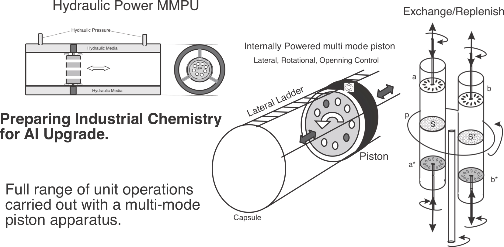
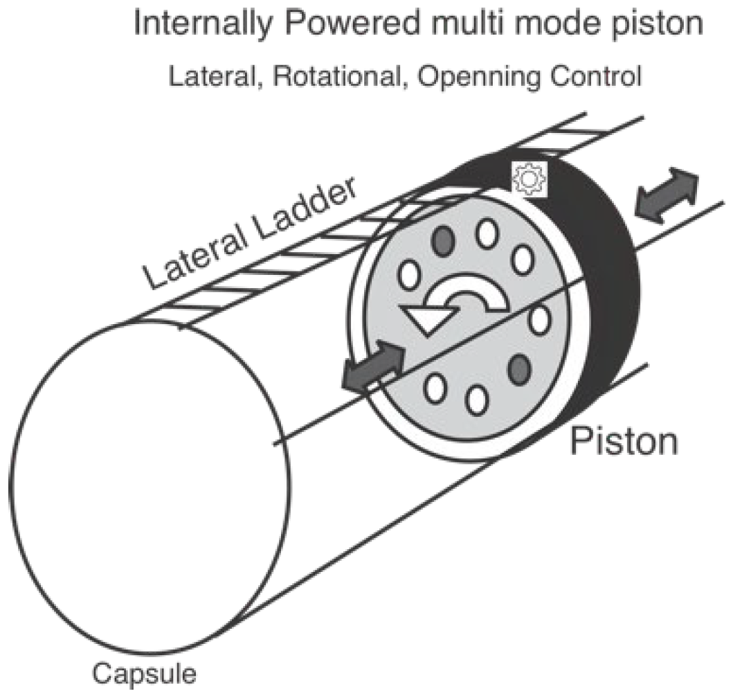
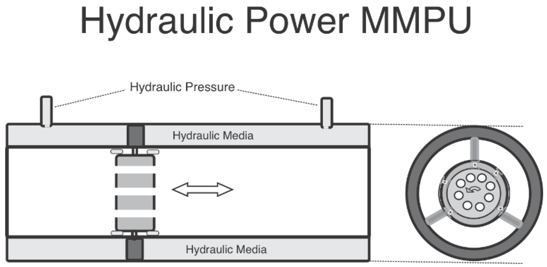
The figure below shows (4) a piston that moves inside its capsule with a cogwheel fitting, operated with a built-in rechargeable battery. It has an internal rotating disc with holes that may be open or closed. The figure on the left (5) shows an MMP designed for high viscosity fluids, requiring hydraulic operation.
Figure 4.
Internally Powered Multi-Mode Piston.
Figure 4.
Internally Powered Multi-Mode Piston.
Figure 5.
Hydraulic Power MMPU.
Figure 5.
Hydraulic Power MMPU.
Let's see what we have so far. This capsule with the holes-drilled rotating piston inside can readily accomplish pumping. First, it sucks in fluid as its holes are closed. The the piston moves back to the edge of the cylinder where the fluid was pumped in from. It does so with all its holes open and the inlet closed. The liquid then has no choice but to flow past the returning piston to the other side of the capsule. Once at the edge, the piston holes are being closed and the piston moves away from the entry edge, pushing the captured quantum of fluid outside the capsule, all the while sucking in the next quantum, and so quantum after quantum the QPM is pumping the fluid forward. Let the capsule be fitted in a pipeline and this creates an in-pipe pump, which may be run on an internal chargeable battery, or on electrical grid, or on steam, or on a combustion engine, or on hydraulics. This in-pipe or in tube-pump works is applicable over a wide range of sizes.
The rotation of the moving piston with some holes open achieves a desired degree of mixing and unlike the situation with the stirred tank, all the parts of the quantum of fluid undergo the same processing and end up in the same degree of mixing. A fluid-to-fluid reaction depends on the degree of mixing, so the QPM is good for pumping, mixing and fluid-to-fluid reaction.
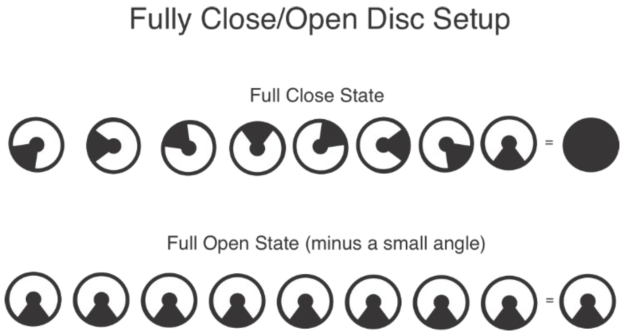
The figure below (6) shows a piston comprising eight independently moving discs that can be arranged to project a closed piston, a fully open piston, and anything in between.
Figure 6.
Fully Close/Open Disc SetUp.
Figure 6.
Fully Close/Open Disc SetUp.
Let's move to separation. Let the quantum of fluid be comprised of two mutually immiscible liquids one H heavier than the other, L. Let some ingredient X be present in L and not present much in H, while the process operator wishes X to change residence to H. The QPM will get L and H to mix and develop a large contact surface between L and H (that what mixing means), X will then migrate from L to H. (If some heat exchange is needed, so be it). Once X migrated to the planned degree from L to H, the capsule can be positioned vertically, allowing gravity to push H down and L up. The piston will move holes-open to the border line between L and H then close the holes and move L and H apart. Mission accomplished. The same trick may be applied to distillation -- the pump is placed on the border area between the liquid phase and the gaseous phase and separation is carried out.
A host of separation processes is based on "flow impact media" -- a certain solid media that creates a discriminating force like in chromatography. The Flow Impact Media, FIM, is also appreciated in a catalytic environment. One can then place the FIM in the inner linings of the holes in the piston, or as a membrane in some holes, through which the fluid is forced to pass and rub against the FIM.
So now we list pumping, mixing, reacting and separating -- all carried out via a QPM comprising a capsule and holes-drilled rotating and straight moving piston: a multi mode piston. (MMP).
Other more efficient QFM will be found down the road. But for now we regard the multi mode piston unit MMP unit (MMPU) as an effective quantum processor module.
We can see several advantages,
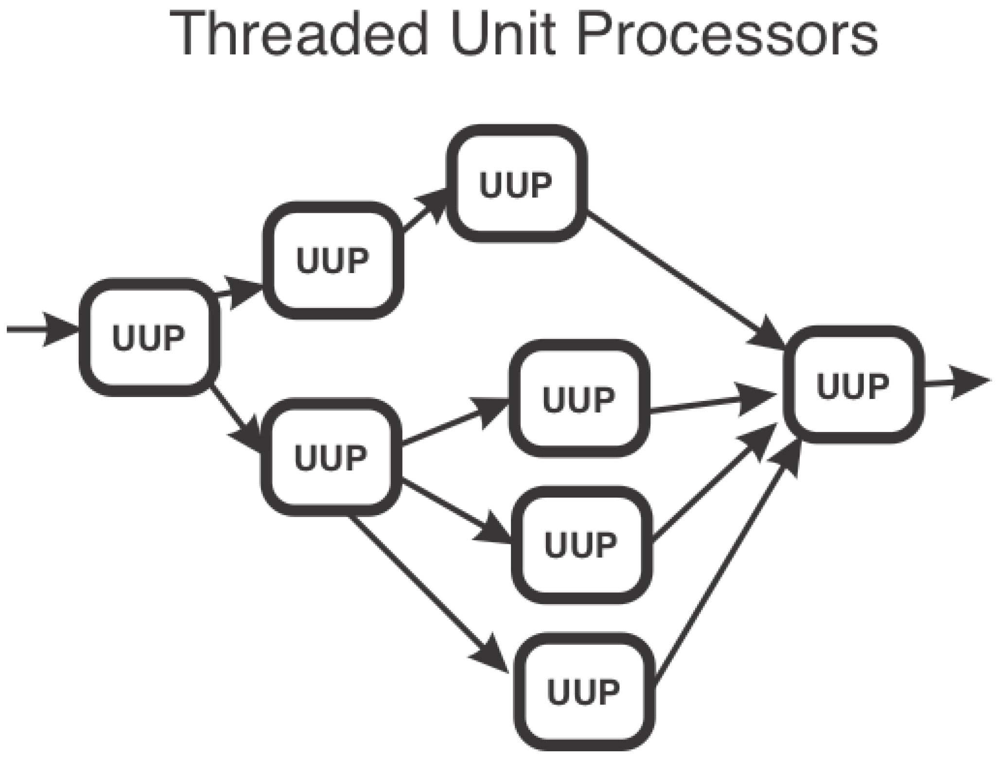
The vision so far is a series of MMP units hooked together such that the output from one is the input of the other. If needed, a capsule feeds to two or more capsules (MMP units), and if needed two or more capsules feed into a single MMP unit and all together we see the MMP unit as a building block for a full-fledged chemical process.
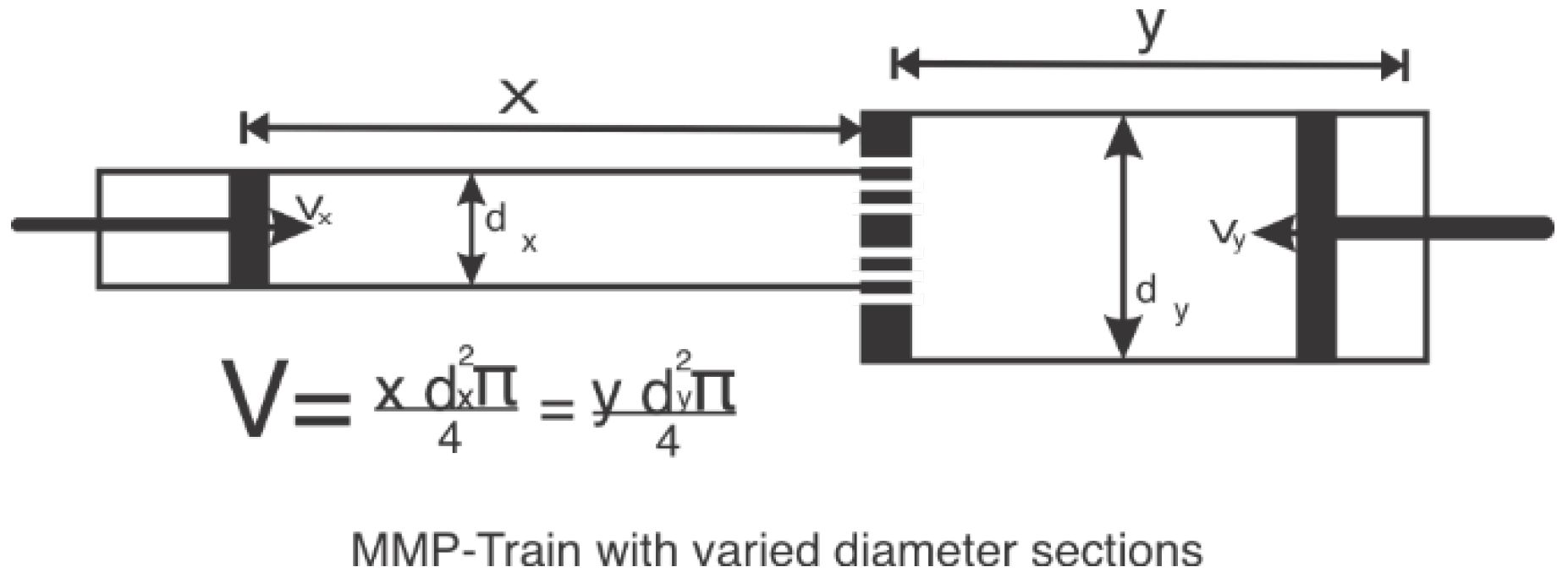
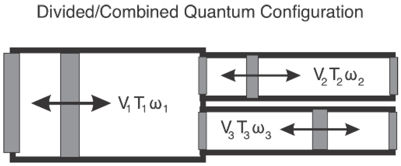
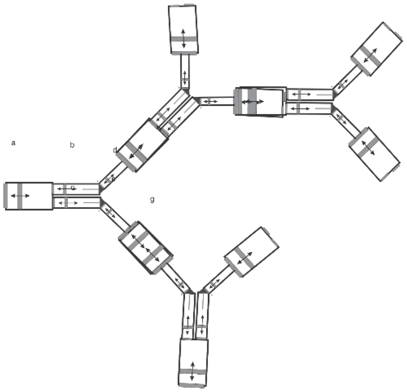
Here below (7) is a depiction of two MMP units hooked together. They are of different diameter but of the same internal volume so that a quantum of fluid from either unit fits into the other. On the right, (8) a division and compound MMP configuration is shown.
Figure 7.
MMP Train with varied diameter sections.
Figure 7.
MMP Train with varied diameter sections.
Figure 8.
Divided/Combined Quantum Configuration.
Figure 8.
Divided/Combined Quantum Configuration.
The MMP units are assembled together "Lego like" (
Figure 9) to represent any a complex fluid processing sequence:
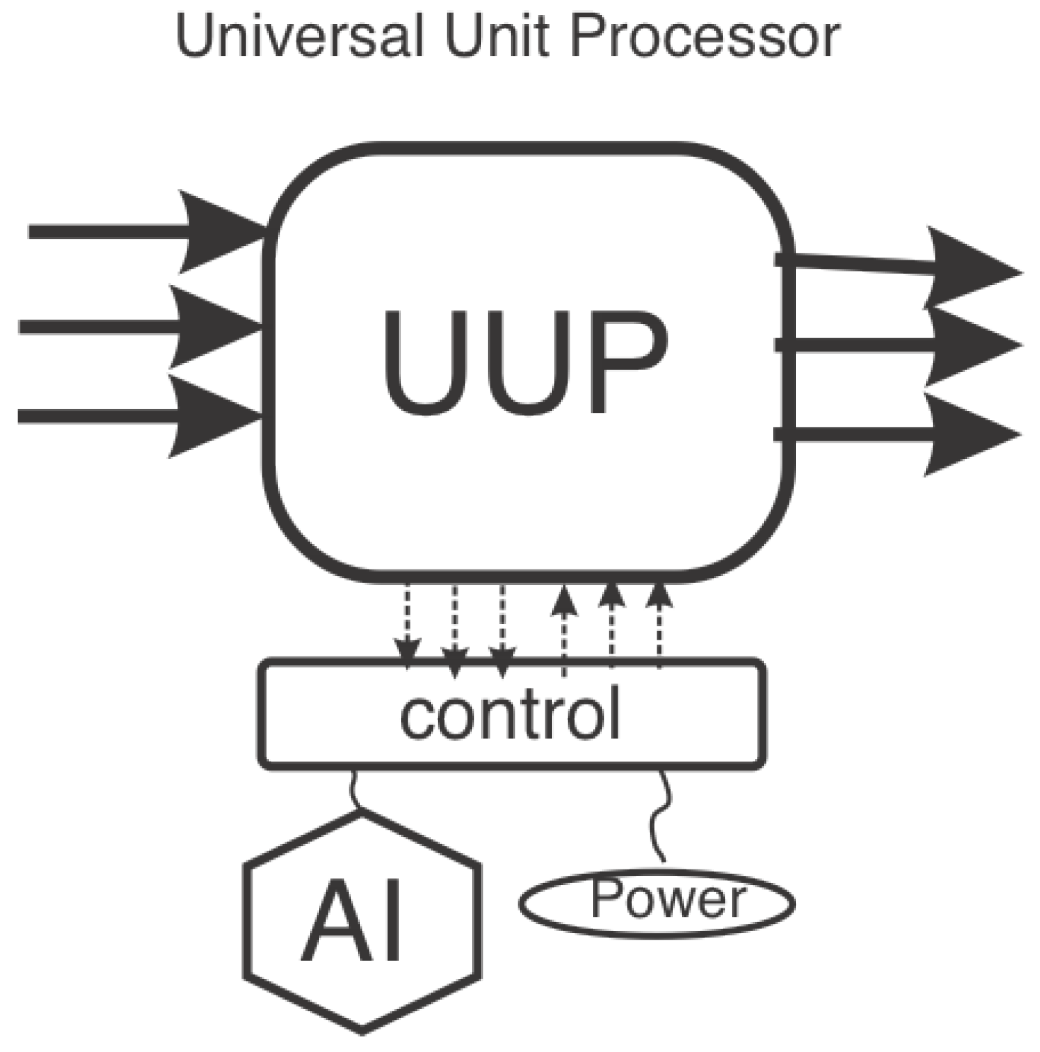
Every MMP unit is fully defined by specifying the position of the piston along its direction of motion, by specifying its rotational state and by specifying the open/close state of all the holes in the piston. This is a time dependent tuple that describes the state of the MMP unit over time. This dynamic tuple defines the applied control strategy. It is perfect raw material for inferential AI neural networks.
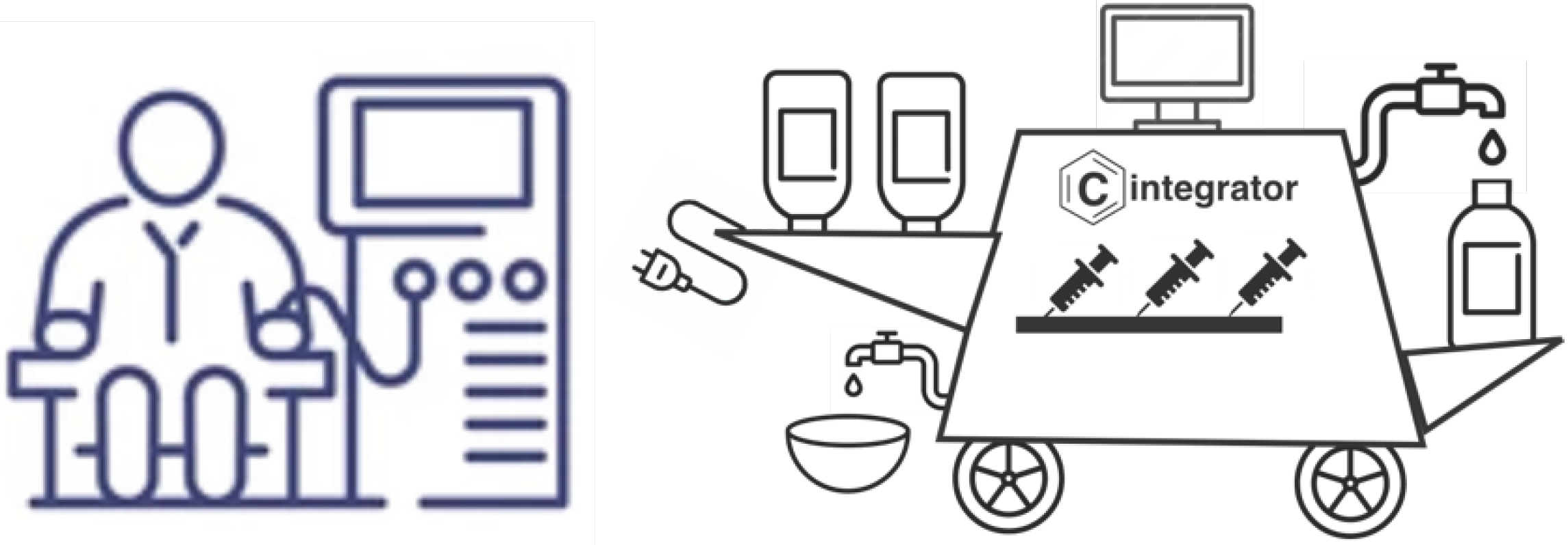
The hooked-up MMPs can fit in a tight place and lead to compact production units that are fully automated and hence can be operated by unskilled operators. See figure below (10)
We learn from AI techniques that the greater the relational similarities between remote elements the greater the inferential output thereto. Thus, the universal structure of the multi mode piston unit that is kept through changes in tasks from pumping, mixing, reacting and separating, the more AI wisdom is expected.
In particular, a chemical process with a required output of Z (barrels/day) can be accomplished by constricting n production lines, each put together from hooked-up MMP units, and each with a production capacity of Z/(n-2) barrels/day. This will allow one to run (n-2) production lines in parallel so that together they satisfy the Z production rate requirement. Two production lines are left idle. One line is taken up for routine maintenance, and the other production line is taken up for upgrading options. The n production lines rotate.
The planners of the production line come up with a strategy S to meet the processing challenge. This strategy is expressed through a table that lists all the values of the operational parameters of the all the MMP units, namely the piston shift position, the piston rotational position, and the states of the holes of the piston.
This digital expression of the production strategy may then be subject to small enough randomized modifications, which in turn create a distinction in production efficiency among the (n-2) production lines. These distinctions are exactly what a standard supervised AI algorithm will need to apply a neural network or equivalent methodology to seek a better and more optimized production strategy.
Unlike customary optimization which is done once and then applied again and again. The strategy described here is dynamic, it keeps changing the recommended optimum, following any de facto changes in the attributes of the raw materials or in the exact requirements of the product, or any new regulations for disposing off the refuse.
The MMP unit can be further optimized per its dimensions. The smaller the diameter of the capsule and the longer the cylinder, the greater the ratio between outside surface to volume, and that implies easier possibilities to apply heat exchange contraptions, or to inject additives, or to fit all sorts of analytics onto the surface. On the counter side, the smaller the diameter the more difficult it is to achieve the desired mixing state. The latter can be compensated by increasing the per capsule processing time, allowing the piston to move back and forth more times to achieve the desired mixing. All these related parameters are subject to optimization.
3.5. A Formal Presentation of the Multi-Mode Piston Unit
Presenting a generic multi-purpose fluid handling dynamic apparatus, a multi-mode piston, MMP, built as a piston moving in direction perpendicular to its surface (lateral movement), the piston is of an arbitrary shape, it is constructed as an external ring that envelops an internal circular part of the piston, a 'disc pack'; the disc pack is independently rotating around the axis of the piston's motion. Alternatively, the piston is circular and without a ring, comprising only a disc pack.
The rotating part of the piston is constructed with holes (fluid passageways) through its surface, where each hole can be of an arbitrary size and arbitrary location, and each hole may independently switch its state between fully open, partially open, and closed; and where at any moment in time the piston may be at a certain lateral position, a certain rotational state, and each of its holes is in a certain state in the open/closed range.
Fluid that flows through the opened holes of the pistons is undergoing a desired process. This piston is controlled by an MMP controller (MMPC) that determines the values of the degrees of freedom of the MMP: lateral position, L(t), rotational position, R(t), and open states, O(t) of its holes (fluid passageways) throughout a range of time t from a preset Tstart to a preset Tfinish.
The width of the MMP, w, is arbitrary. In certain embodiments the inner walls of the holes are lined up with fluid-impact media, FIM, that changes certain attributes of the passing fluid. The holes are either empty or stuffed with a fluid-impact porous media; fluid impact is exemplified by the following partial list: (i) catalysis of a chemical reaction within the fluid, (ii) reaction between the fluid and the fluid-impact media, (iii) separation between ingredients within the fluid.
The MMP may be moved laterally with a rod perpendicular to its surface and where the rod is being moved along its axis through an external power source, and where the rod is rotated with an external power source, and this rotation rotates the piston attached to the rod.
The holes in the MMP are generated by either:
(i) constructing the disc pack as a pack of adjacent discs with holes in them, where the discs rotate independently so that they are configured for (i.i) a state of no overlap between the holes of the discs, which is a state of "closed" for the piston, or (i.ii) the discs are configured to create full overlap among the holes of the discs, which is the state of "fully open" for the piston. In a third option (i.iii) the discs are configured with a partial overlap among the holes of the discs. This is the "partially open" state. The degree of the state of being open is determined by the degree of overlap among the discs of the pack.
The mutually adjacent discs receive rotation power by either one of the following ways:
(i.a) each disc is attached to a rotating rod, where the rods of the adjacent discs are concentric, each with a different diameter, and each is rotated individually through a power source outside the MMP;
(i.b) an internal battery which is charged either by wire or wirelessly;
(ii) constructing the disc pack with a pivot next to each hole, the pivot secures a hole-shaped plate, a "rotating cover", that may be aligned with the hole and cover it completely, or may be rotated away from the hole and open it completely, or it may be placed to partially overlap the hole and keep it partially open, the rotating covers are powered by an internal battery.
Alternatively, the discs are connected to concentric rods so that each concentric rod can be independently rotated in order to achieve the desired state of overlapping among the holes of the discs.
Pumping:
In-line Pumping is done through the following steps:
(i) the MMP is put in a 'closed' position with respect to all its holes.
(ii) the MMP is moved inside the pipe with the fluid to be pumped. The movement is in the direction of the pumping, from a starting position Pstart to a finish position Pfinish, thereby pushing forward the fluid ahead of it, and sucking towards it the fluid behind it.
(iii) the MMP is switching to fully open states for all its holes.
(iv) the MMP is moving back from point Pfinish to point Pstart, while the fluid ahead of it flows through its holes to behind the MMP.
This sequence repeats for as long as it is desired to keep the pumping operation of the MMP.
Mixing
Mixing is carried out as follows: let a quantum of fluid be sucked in from the left circular edge of the cylinder, and be pumped out from the right circular edge of the cylinder, when the quantum of fluid is fully sucked into the capsule the following steps are carried out:
(i) both edges (stationary MMPs) are set into "closed" state
(ii) the moving MMP is positioned abreast of the right edge, and is set to "open" state
(iii) the moving MMP is moving right to left while rotating thereby mixing the quantum of fluid in the capsule. When the moving piston arrives at the left edge, it reverses cours and returns to the right edge, to finish one out of several cycles that are practiced until the quantum of fluid in the capsule is mixed to a desired degree. When the state of desired mixing has been achieved the moving piston is positioned abreast of the left edge of the cylinder, switches to fully closed state while the two stationary pistons (the edges of the capsule) switch to open state; the piston then moves to the right edge thereby pushing out the quantum of fluid inside the capsule, and sucking in a new quantum of fluid, to be mixed as the former one was, so continuing as long as fluid is available as input.
Reactions
Using the MMP to carry out in-fluid chemical reactions one would be applying any necessary heat-exchange apparatus around the capsule, and as necessary inject into the capsule any required additives. The movement back and forth of the MMP will continue until the desired reactions achieved their designated status.
Separation
To satisfy a need for separation between two constituents A and B within a fluid, where the separation is effected through a fluid-impact media which discriminates between A and B, A being attracted to the fluid-impact media, B being rejected by the fluid impact media, the moving MMP is creating a fluid flow in contact with the fluid-impact media such that fluid that emerged from behind the moving MMP is richer with constituent A and the fluid that is ahead of the moving MMP is richer with constituent B, thereby there exists a point x between the right edge of the capsule, Er, and the left edge of the capsule El where the fluid between the MMP and El is optimally richer with constituent A and the fluid between x and Er is optimally richer with constituent B, the two parts of the quantum of fluid are then routed to different destinations where each part can separately undergo the same separation procedure. This sequence is repeated an arbitrary number of times to achieve an arbitrary level of separation between constituents A and B.
An arbitrary number s of holes in the MMP is fitted with the fluid-impact media, (the fitted holes), and an arbitrary number f of holes in the MMP are free from the fluid-impact media, (the free holes) to generate the separation between constituent A and constituent B the MMP moves through the capsule captured quantum of fluid with the fitted holes open and the free holes closed.
The separation happens when the two edges are in closed position and the moving MMP moves from El, towards the other edge, Er , forcing the fluid to pass through the open fitted holes, so that at a certain point x between the edges a degree of separation is achieved, then the fitted holes are closed, and the free holes are opened; the MMP then reverses it motion, moving from point x to the El until it is located abreast of El, at that point the part of the quantum fluid between El and point x is richer with constituent A and the part of the quantum fluid between point x and Er is richer with constituent B. Next the MMP then is switching all its holes into a closed state and moves from El towards point X, at the same time the holes in both edges are switched to open so that the movement of the MMP from El to point X pushes the B enriched part of the quantum of fluid outside the capsule to a receptacle planned to collect the B enriched part of the quantum of fluid, Rb, at the same time a new quantum of fluid is sucked into the capsule through El.
The MMP unit can readily be applied to volatility based separation. Let's desire to separate a fluid Q comprising a more volatile component Q' and a less volatile component Q" to two parts one richer with Q' and the other richer with Q", the separation is achieved as follows:
The MMP unit is set to a vertical position, then a quantity of Q in a liquid phase Ql is pumped though the bottom edge of the MMP unit so that it fills the MMP capsule up to a point x lower than the high end of the MMP unit, and where the MMP is positioned at point x such that the atmosphere is above it, and a quantum of liquid Ql is below it. Then the bottom edge of the MMP unit cylinder is put in a closed state while the moving MMP is also set to a closed state. Then the moving MMP is rising and thereby generating vacuum below it which is filled with fluid Q in the gaseous phase, where the more volatile component Q' is richer in the gaseous phase while the less volatile component Q" is richer in the liquid phase. When the MMP reaches the upper edge of the MMP unit, then the fluid below it is partly liquid Ql and partly in gaseous phase, Qg. Then the upper edge holes are set to close, the holes of the moving MMP are set to open and the moving MMP is moving down through the gaseous phase of Q, Qg , until it touches the surface of the liquid phase of Q, Ql, then the holes of the moving MMP are being put into the closed state. The holes on both edges of the cylinder are set to open and the moving MMP is rising towards the upper edge, this movement pumps the liquid phase Qg to a receptacle outside the MMP unit, while more liquid Q is feeding into the bottom of the MMP unit from a feed source.
The moving MMP is then put again in closed state and the liquid below the piston is pushed down to point x, at which point the above distillation sequence is repeated.
Configuration
Any number of well-tailored MMP units may be assembled into a general purpose fluid handling system - a combined fluid operating facility, MMPF, that applies a sequence of chemical engineering unit operations on a set of input raw materials, to generate a desired product, and dispose of parts of the raw materials that did not convert into the desired product.
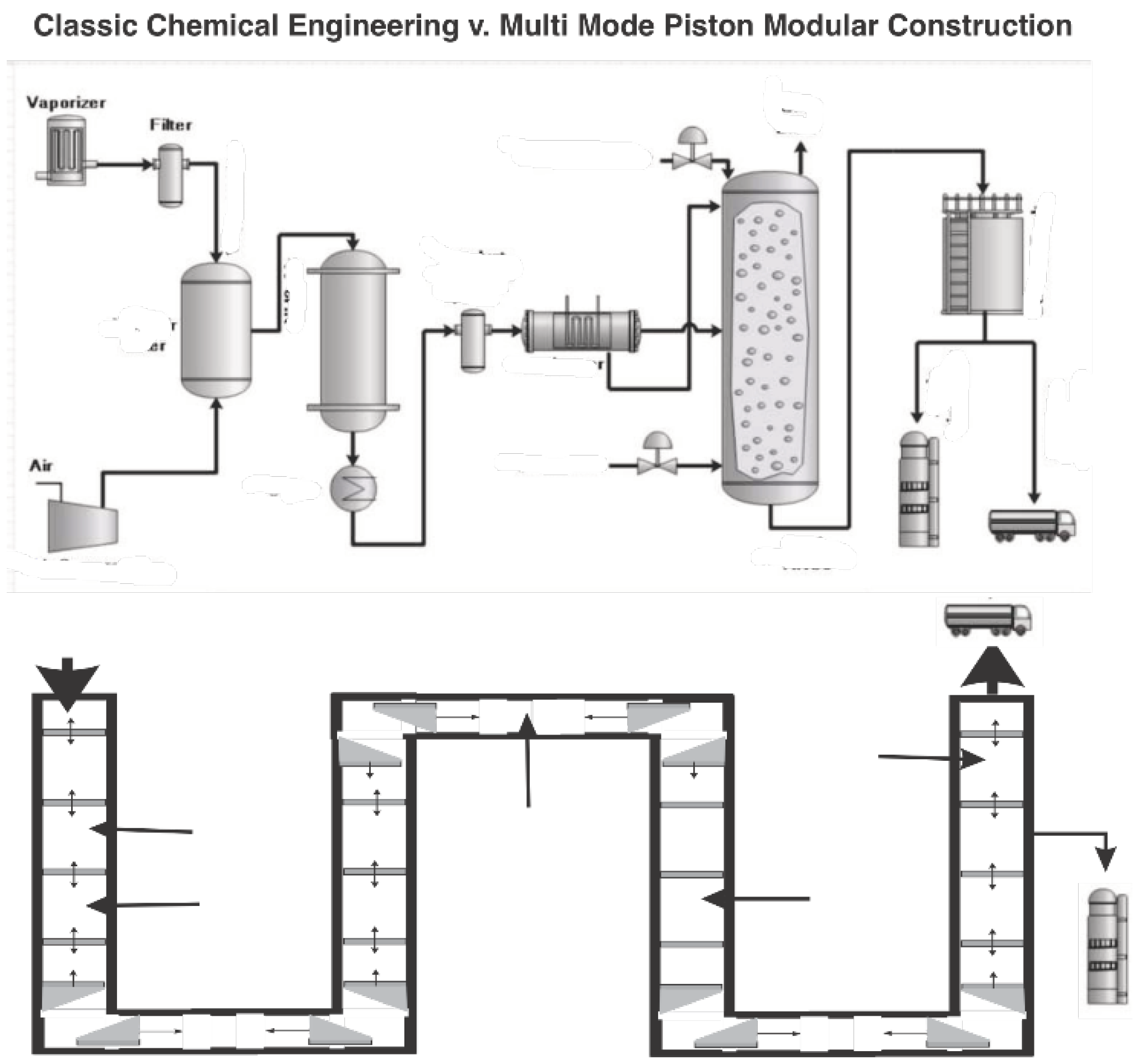
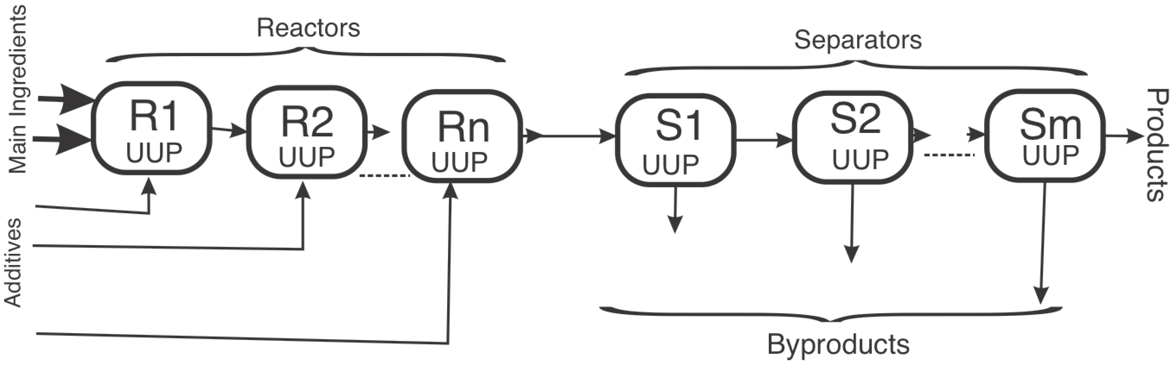
The figure below (11) compares the standard continuous operational mode with the proposed quantum fluid operational mode.
Figure 11.
Process Integration.
Figure 11.
Process Integration.
The MMP units (MMPU) are connected either directly or through capacity tanks. The MMPF is controlled from a central control station that activates and operates the MMPs to coordinate a desired production line for a fluid product. The MMPF is a linear connection of n MMP units, U
1, U
2, .... U
n, such that unit i feeds into unit (i+1) where i=1,2,...n-1, and where
where V
k is the volume of the quantum fluid that is contained in unit k, T
k is the time a quantum of fluid is being processed in unit k. and T
restk is the time a quantum of fluid is resting in unit k, before or after its processing, where i,j,k = 1,2, ...n, and where i ≠ j.
The various MMP units may share a geometric direction, (linear setting) or the MMP units are being set at an angle towards each other in which case the shared edge of two non-linear MMP units will be of angular shape to ensure that fluid from a first MMP unit flows to the next in line MMP unit.
The MMPF is set up such that an MMP unit, Uf (the feeding unit) is feeding into t MMP division units where each of the input edges in the division units. U1, U2, ... Ut has hi holes, where i=1,2,...t. We set for the feeding unit to have f = Σ hi holes, summarized over a subset Y of the division units, and where the feeding unit is feeding to the division units in the Y subset, the f holes in the feeding unit are open and the holes in the units of the Y subset are open, while the holes in the units which do not belong to the Y subset are set to a closed state. The feeding unit may feature less than f holes, but rotate so that its feeds is divided between the divisions units of the Y subset.
Similarly, for a different network configuration the MMPF is set up such an MMP unit Uc, the collecting unit, is collecting fluids feeding from t' MMP feeding units where each of the output edges in the division units. U1, U2, ... Ut' has h'i holes, where i=1,2,...t' and where the collecting unit has c = Σ hi holes, summarized over a subset Y' of the feeding units, and where the collecting unit is being fed from the feeding units in the Y' set while the holes in the units which do not belong to the Y' subset are set to a closed state, and the collecting MMP is rotating so that the fluid contents of the collecting MMP is collected from the feeding units of the Y' subset.
Generalizing Hardware, Tailoring Software
The universal structure of the generic chemical engineering building block allows for prime attention to be paid to high quality design of the multi-mode piston unit, spanning sizes, and applications. The market will be filled with many standardized MMPU which every process designer will select from, and then apply the control strategy that represents the process under design. The attention of the industrial chemist and the chemical engineer will be directed to procedural steps while the hardware MMP units will be a standard issue. This is a much better use of the planning time of the process designer.
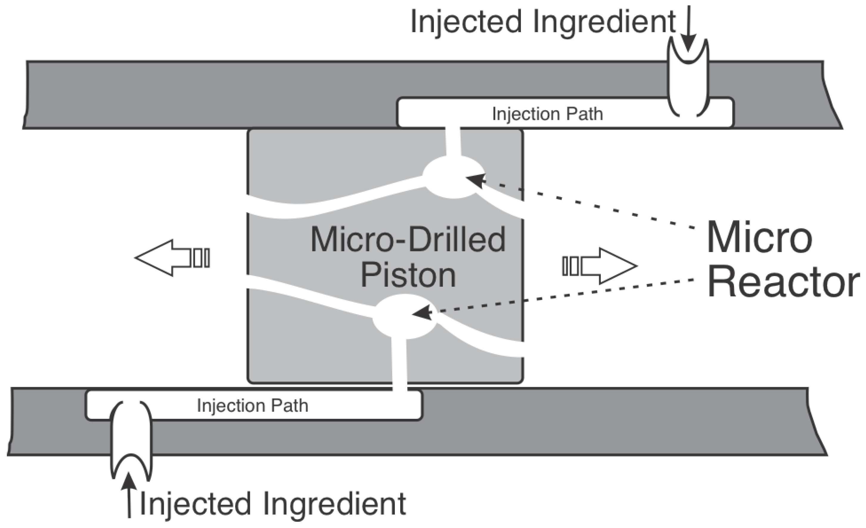
Micro Drilled Piston
As of now the multi-mode piston (MMP) is the only UUP under a testing state. In preliminary design mode we find the micro-drilled piston. This is a piston comprising micro tunnels that pitch together the content captured in the capsule with carefully pushed in add-on ingredients to an action spot which is controlled per temperature and any other environmental parameters. Micro channel pistons can be manufactured through 3D printing or through more traditional methods involving melted material engulfing washable content. See
Figure 12.
Integrated Motion
The MMP integrates fluid motion power with fluid reactivity and behavior. Classically chemical processes are happening through externally activated pumps that move the fluid through the sequence of steps. The MMP integrates power with behavior. This integration is essential for the AI impact, assuring optimality. The structural similarities between the various functions: mixing, reacting, separating, create a unified database for the AI to chew on. In the future the AI database will serve to recommend the dimensions and the structure of particular MMPs for specific needs.
Equipment Capacity Management
Traditionally a chemical engineer will build the plant to fit the required production capacity. The size of the reactor, the separators, the in-between tanks, the storage tanks, the pumps are all derived from the desired throughput. It is generally very costly to use two twin production lines, with double the number of units, pumps, control wiring etc. This rigidity is alleviated with the UUP. Being of standard structure the UUP are built very economically. They handle their own fluid motion power, and their own timing. It makes much more sense to achieve the desired plant throughout through two or more parallel lines. What is more, any particular UUP can be duplicated or triplicated, so that maintenance and enhancement can be applied to the plant while keeping the production hamming. Having n parallel production lines will create an n multiplier for AI data collection, yielding faster optimization.
Delay Management
Each UUP in the sequence is designed to finish its process with the current quantum of fluid, QoF, over the same time interval T which is claimed by upstream and downstream UUP. This is necessary for a smooth progress of each QoF from the first UUP to the last. Any delay within one UUP will slow down the whole process. To alleviate that delay option one could fit two or more parallel UUP for processes inclined for delay. Such may be in cases of random contamination of feed. Overall faster UUP will be programmed to wait for slower UUP. See
Figure 13.
Content Monitoring
The QoF encapsulating cylinder may be fitted with radiation sensors which examine absorption at given wavelength and return measurements of concentration and chemical makeup to indicate to the control system the extent of readiness of the QoF to be released to the next step.