Submitted:
02 August 2024
Posted:
05 August 2024
You are already at the latest version
Abstract
The ever-growing concerns about global warming and the rapid depletion of fossil fuels have triggered a rising interest in research for cleaner, more efficient and cost-effective energy generation. Organic Rankine cycle systems have immense potential to become a strong alternative to conventional methods of energy generation. However, such systems’ efficiency is limited by the performance of the incorporated gas expanders or prime movers. Conventional gas expanders often utilize ports or cam-operated valves. Ported expanders offer limited efficiency and controllability, and produce high emissions causing a large amount of heated and compressed gas to be wasted. Cam-operated valves, in contrast, increase expansion performance compared to ported expanders, however, they have no variability and adaptability to changes in system parameters such as gas pressure, temperature, dryness fraction, and load variation to name a few. On a positive note, this issue can be addressed by adopting a variable timing and fast-operating, control valve with an accurate and adaptive control mechanism at the expander inlet. A properly designed and controlled valve can greatly improve the system performance of gas expanders and pave the way for an efficient low-cost alternative energy generation. This manuscript provides a comparative review of recent progress on the design, modeling, optimization, and control aspects of valves for gas expanders. A clear pathway on the scope of further development is also drawn based on the present state of the art.
Keywords:
gas expander
; energy conversion
; actuators
; control valve
; control system
; valve optimization
1. Introduction
Organic Rankine cycle (ORC) is a closed-loop energy conversion system, similar to the traditional steam cycle, that uses organic fluids instead of water as a working fluid. The organic working fluid, which has lower boiling temperatures, circulates through the ORC system and helps transport and transform the heat into usable mechanical and/or electrical power. ORCs have been in existence for a long time but have recently re-emerged due to the ever-growing concerns of fossil fuel consumption and the resulting environmental effects. Being able to operate in low-temperature conditions, the ORC system can effectively harness heat from different renewable sources such as solar irradiation, biomass, geothermal, industrial waste heat, etc.
Although ORC systems offer great potential, they suffer from low efficiency. ORC system efficiency, in general, is within the range of 9.6\% to 18.1\% and depends on factors like working fluid selection, expander efficiency, evaporator, and condenser temperature, etc. [1]. Expander, which lies at the core of an ORC system, is critical to the cycle efficiency. The usable energy conversion of the ORC cycle occurs at this expander where the high-pressure fluid expands while flowing from its inlet through to the outlet port and fluid energy is converted to mechanical and then often to electrical energy via a coupled generator. The low thermodynamic efficiency of ORC cycles due to low-grade temperature sources demands an efficient expansion process to achieve a satisfactory and workable overall thermodynamic cycle efficiency [2]. The type and design of the expander used in low-grade heat and waste heat recovery systems are critical for its performance, efficiency, and economy. In a broader sense, expanders can be classified into two groups either turbo-expanders or volumetric expanders [3]. However, volumetric expanders are suitable for small-scale systems with power outputs of 1∼20 kWe [3]. Thus this manuscript will only concentrate on these types of expanders.
Volumetric expanders are sometimes equipped with cam-operated or mechanically coupled fixed-response valves at their inlet openings. The inlet valve is initially open to allow compressed working fluid into the chamber and after a certain duration, the valve is closed to allow the fluid to expand before discharging through the discharge port. The timing and speed of valve operation play a crucial role in improving system performance. Liguang et. al. [4] tested the effect of inlet valve closing timing on the performance of a gasoline engine and found out that an electronically controlled variable inlet valve’s closing timing can be an important instrument in increasing power output, decreasing fuel consumption, and greenhouse gas emissions. Sultan [5] conducted a case study to demonstrate the performance of a limaçon gas expander with and without a cam-operated inlet control valve and found the isentropic efficiency in the first case to be increased up to 23.85% with less than half of the flow rate of the later. Although initially the output power drop is recorded due to reduced flow rate, it is increased to a desired level with some geometric design optimization [5]. Benstead et al. [6] claimed in their patent that a control valve with a pulse width modulation (PWM) control scheme can be used as a means to improve the operation of a positive displacement expander. Similarly, Chotai et al. [7] reported an increase of 35.67% in the efficiency of a cam-less engine just by appropriately controlling the inlet flow cut-off timing. Therefore, the expanders used in the ORC systems, that badly suffer from low efficiency, could be made more efficient by introducing an optimized valve at their inlet to regulate the flow of working fluid and ensure improved isentropic and volumetric efficiencies as defined in [8].
A control valve is a power-operated device that regulates the fluid (such as gas, water, or oil) flow rate by adjusting the position of the valve plug or valve disk to maintain a process variable (PV) as close as possible to the desired set point (SP). A PV can be any system parameter including connected load, inlet pressure, temperature, and flow rate. A control valve is the final element of a control loop that implements the desired control strategy as determined by the controller’s output. An ideal control valve should be able to direct the flow of working fluid without any external leakage and withstand operational temperature, pressure, corrosion, erosion, and other factors that can affect the valve actuation.
2. Utility of Inlet Control Valve in Gas Expander Operation
A volumetric gas expander is an energy conversion device that converts the potential energy of the compressed working fluid into mechanical energy by allowing the fluid to expand inside the expander chamber. In its basic form, a gas expander is equipped with a piston or rotor inside its housing. Figure 1 represents a basic schematic diagram of a reciprocating type volumetric expander with a cam-operated valve that is mechanically coupled with the action of the piston. This type of valve has a fixed response, i.e. the valve opens and closes at a certain piston position and can not be controlled to operate otherwise. The compressed fluid enters the chamber through the inlet valve at high pressure forcing the piston towards the discharge port. This increases the control volume and the fluid pressure remains constant till the maximum chamber volume is reached and the fluid is exposed to the discharge port dropping the chamber pressure. As the amount of fluid entering the chamber is not regulated, the compressed fluid fills the total control volume and can not expand. This results in much of the costly fluid being forced out through the discharge port before being able to expand adiabatically inside the chamber.
This waste of energy can be avoided by replacing the fixed-type mechanical inlet valve with a controlled valve with variable operating capability. Figure 2(a,b) shows the P–V diagrams of the expander with a fixed/cam-operated valve and a flexible-response controlled valve, consisting of four processes including filling, discharge, return, and compression. The cam-operated valve operation is not flexible and the open/close positions are fixed as seen in Figure 2a. With this fixed valve configuration, the amount of fluid inside the chamber is always the same producing a certain amount of energy in every cycle of piston/rotor motion provided the supply pressure is constant. The energy produced can be regulated by regulating the supply tank pressure. However, regulating the supply tank pressure by throttling would cause a loss of energy reducing the process efficiency.
On the contrary, the externally controlled valve operation is flexible and can be opened/closed at any precise piston/rotor position to allow or cut off the flow. This allows the amount of fluid inside the chamber to be regulated resulting in an improved expander efficiency. Besides, the regulation of energy production using an inlet control valve would provide the expander the ability to cope with load variation. Moreover, at the start of the expander operation, usually a higher force/torque is required to push start the piston/rotor from rest. With the flexibility of a controlled valve, it would be possible by allowing a large amount of fluid needed to provide that extra push. When the piston/rotor achieves the rated speed, the flow rate could be deregulated to a lesser amount needed to meet the load demand only. This can be realized solely by controlling the instance of valve operation with respect to the position of the piston/rotor.
3. The Challenge
As discussed above, a flexible, precise, and fast-acting inlet control valve would theoretically improve the efficiency of a gas expander. However, there are a number of challenges that need to be addressed first. The position of the piston/rotor at which the valve needs to operate to ensure intended expander efficiency is crucial. The valve response time would play a vital role in that regard as the valve may require to operate within a very small time slot in the thermodynamic cycle. An example would be more suitable to explain. Assume a limaçon expander with a rated speed of 800 rpm and the inlet valve needs to close at the 90 deg angle of rotor angular displacement. For this setting, the available time for the valve to operate from the cycle initiation would be, . This available time slot is very short and the valve needs to be accurate as well as fast enough to meet the requirements. The actual time may be less as the valve needs to open at the start of the cycle as well. Moreover, if the expander is double acting such as in limaçon machines, the valve needs to operate twice in each cycle [9,10]. Therefore, the valve operation would need to be repetitive and fast. Besides, being an electromechanical device, the valve will be subject to response delays due to factors like current buildup, inertia, and damping. This emphasizes the importance of inlet valve design, optimization, and control. The design should be optimized to ensure a fast repetitive response with minimum hysteresis and delays. However, there would still be some actuation delay. Here, the control system will come into play. A well-designed and optimized control system will take the delay and other factors into consideration and can energize the valve at an earlier expander angle so that the actual operation takes place at the predefined angle (90 deg for the above example). The control system can also redefine the actuation angles to meet load demand or to counteract any operational changes. In the following sections, a detailed literature review of the recent advancements in the design, modeling, optimization, and control aspects of control valves is provided along with the current knowledge gaps and the prospective scope of future developments.
4. Control Valve Designs
Control valve has been a key component in many process control applications in industries ranging from mobile machinery to energy generation [11,12,13,14,15]. Control valves used in industry can be classified into different categories depending on their mechanical design as shown in Figure 3.
Control valves driven by pneumatic, hydraulic, and electrical forces have been developed and applied to sophisticated control problems. Table 1 below provides a summary of different types of valve actuators, their mechanisms, and their pros and cons. Also included in Table 1 is the research done on these valve actuator types.
Several types of control valves have been reported in the literature as seen above. However, due to the emergence of complex machines and the ever-growing demand for efficient and precise operational control, traditional hydro-mechanical control valves have difficulty coping with the performance and precision requirements. Therefore, optimum designs and new technologies such as Digital electronic systems and alternative driving mechanisms such as nonlinear servomechanisms and piezoelectric actuators are being tested and implemented in control valves nowadays [34,35,36]. Therefore, this manuscript will only concentrate on the recent developments in control valves including solenoid, motor, and servo valves.
4.1. Solenoid Valve (SV)
Electromagnetic solenoid-based low-cost electromechanical actuators have been widely used in versatile industrial applications ranging from automobiles to state-of-the-art robotics due to their efficiency, speed, controllability, cost-effectiveness, and simplicity [37,38,39,40,41,42,43,44,45]. A solenoid converts electrical signals at its coil into electromagnetic energy and output mechanical kinetic energy to perform mechanical work through its armature-plunger arrangement [46]. An SV system is primarily composed of an electrical subsystem, a magnetic subsystem, a mechanical subsystem, and sometimes a fluid flow subsystem depending on its application as shown in Figure 4a below.
Figure 4a shows the basic structure of an SV. When an electrical voltage is applied to the solenoid coil, a magnetic field is developed due to the flow of current through the coil. This magnetic field produces an electromagnetic force to attract the armature. On the contrary, when there is no input voltage, there is no electromagnetic force, and the armature returns to its initial position by a spring. Although solenoid valves are popular due to their ease of design, they suffer from time delays. It takes time to build up magnetic energy in the coils and move the plunger thereafter. The actuation delay is usually smaller in direct-acting solenoid valves compared to pilot-operated solenoid valves [47,48]. This is because the pilot-operated mechanism employs a solenoid-actuated pilot spool that activates a secondary hydraulic or pneumatic mechanism to actuate the primary valve spool. The total delay corresponding to the actuation of pilot and valve stages accrues over an actuation cycle. Whereas, in direct-acting valve, there is no pilot stage and the delay is only due to the actuation of the solenoid valve spool.
The work done on thermo-electromechanical analyses of solenoid valves by Angadi et al. found that solenoid valves offer lower reliability due to their susceptibility to thermo-mechanical failure at longer operating time and higher current and temperature [46,49]. However, further research has been carried out to minimize the delay and improve the dynamic characteristics of solenoid valves by optimizing their driving circuit and control strategies. Li et al. [48] proposed a double voltage driving circuit for a high speed on/off valve (HSV) which can generate a high driving current producing a faster response. Similar multi-voltage driving circuit approaches are also available which can decrease the closing time of HSVs [50,51]. Zhong et al. [52] reported a PWM based control scheme for HSV with an improvement of about 23.6% and 17% for opening and closing times, respectively. Yang et al. [53] proposed a fast-acting solenoid valve for diesel engines having a response time of ms and flow rate of 35 L/min by performing structural and material modifications and utilizing a demagnetizing mechanism. A higher flow rate of 460 L/min has been achieved by Topçu et al. [32] only to sacrifice the response time to ms. Although SV systems suffer from a delay in response, they can be made fast and cost-effective by optimising the design parameters and control mechanisms; this will be discussed in Section 6 and Section 7. The lack of comprehensive studies on the use of SV in expanders has great potential to be investigated. One important factor that has not been discussed in the literature is the heating effect and the resultant energy loss of solenoids at a high frequency of operation. This particular aspect of SV systems can be overcome by a proper design of the SV duty cycle. The use of push-pull SV can also be helpful in terms of improving response time and lowering losses.
4.2. Motor Operated Valve (MoV)
Similar to SV, MoV is an electromagnetic valve that inherently produces rotary motion with the aid of electric motors. Figure 5 shows a general schematic of a direct drive rotary MoV where a motor drives a valve spool to regulate the fluid flowing through it.
Different electrical motors have been recently utilized as valve actuators. For example, Jiang et al. [54] proposed a fully variable valve actuation system using a brushless DC motor. The authors reported a 8 mm valve lift and a 16 ms opening response time. In a more recent work by Hossain et al. [8], the authors proposed a stepper motor-operated valve for limaçon expanders and showed that the introduction of the valve could increase the expander’s isentropic efficiency by 14.88%. A combination of multiple motors can also be utilized for valve actuation such as that proposed by Rybarczyk [55] where he provided a mathematical model of an electrohydraulic valve composed of a stepper and a DC motor. This innovative valve however has a slower response time of s at 87% valve opening. Besides DC and stepper motors, voice coil motors have been used as valve actuators which can provide actuation force in the range N to 1000 N and a stroke up to 100 mm with a motion frequency of up to 1 Hz; e.g., Han et al. proposed a proportional hydraulic valve using a voice coil motor in conjunction with a lever arrangement for a water hydraulic system [56]. The authors reported delays of 30 ms and 35 ms for opening and closing respectively. Similarly, Zhang et al. [57] proposed a voice-coil-motor-operated direct drive valve. Besides Chen et al. [58] showed that a permanent magnet torque motor can also be used as a servo valve actuator.
4.3. Electromagnetic Servo Valve (ESV)
A more accurate, energy-efficient, and reliable control valve compared to direct drive SVs and MoVs are the servo valves which have seen major use in high frequency and high-pressure applications [59,60,61,62]. These valves are a form of proportional pneumatic or hydraulic valves actuated by pilot spools controlled by solenoids, electric motors, or some other electromagnetic mechanisms as shown in Figure 6. The pilot spool then actuates the hydraulic piston actuator by creating a difference in pressure in the piston cylinder.
Servo valves have a larger power-to-weight ratio and do not possess heating problems like SV and MoV [63]. However, ESVs have added drawbacks of high expense due to their complex architectures. Li [64] presented an unconventional, less expensive design of a servo valve consisting of a pressure control pilot and a boost stage using individual spools that are controlled independently at valve input and output. However, Li’s design suffers from a limited dynamic performance that can be improved by adjusting the spool area or flapper stiffness. Although the modification produces better performance, the effect of pressure force on the optimized design has not been performed. A different attempt by Meng et al. [65] to reduce the overall cost of manufacturing results in an introduction of a maglev coupling between the actuator and valve body. Though the maglev-based ESV produces a fast response at high pressure, the performance deteriorates considerably at lower pressures. For example, in Meng’s design, a decrease of pressure from 21 to 3 results in an overall 40% increase in rising time. Besides, it has higher hysteresis (1.31% more), lower flow rate ( L/min), lower bandwidth and higher leakage ( L/min) compared to traditional 2D valves. Other works worth mentioning include a new servo valve design by Zhang et al. [66] for high torque requirement applications (47-52% increase in output torque) by changing the magnetization patterns of the permanent magnet motor. Karunanidhi et al. [67] on the other hand addressed the limited bandwidth issue of traditional torque motors used in servo valves and proposed a magnetostrictive actuator suitable for high-speed applications. Another design of a 2D, 3-way servo valve was proposed by Zhiwei Li et al. [60] with the spool having two degrees of freedom. Although the design is lighter weight and has better performance than traditional servo valve designs, the response time of 43 ms is much higher than SV and MoV discussed earlier.
In general, servo valves are extensively used in the control industry, due to their precision in position control and higher torque generation but they suffer from complexity in architecture and operating mechanism accompanied by high overhead and maintenance costs. The response time of ESV is also much higher compared to SV and MoV.
4.4. Piezoelectric Servo Valve (PSV)
Piezoelectric material-based actuators have the potential to be a faster and more efficient alternative due to their minuscule response-ability and lower power consumption. Compared to electromagnetic actuators having a switching time of 10-20ms, piezoelectric actuators can switch in the range down to 0.1-0.5ms [36]. These actuators perform mechanical motion by a phenomenon called inverse piezoelectric effect where a voltage applied across a piezoelectric material causes its shape to change which can be utilized as a valve action as shown in Figure 7. Regardless of having better performance than a conventional servo valve in terms of response time with minimum moving parts and simpler design, piezoelectric valves have not gained much popularity due to their strong hysteresis phenomenon.
The nonlinear hysteresis character can be linearized as shown in Ikebe et al.’s work [68] in which the author proposed a flapper type servo valve using the piezoelectric quartz strip and utilized the PWM control method. In recent studies, Gui et al. [29] used an elitist non-dominated sorting genetic algorithm-II (NSGA-II) to optimize the design parameters of the main spool of a piezoelectric servo valve and found that the dynamic bandwidth can be increased up to 26%; Ling et al. [30] developed a piezoelectric servo valve having a response time of ms and dynamic bandwidth of 120 Hz for micro-fluid displacement control. In the later study, the two-stage servo valve has a better dynamic bandwidth compared to ESVs but only provides a mere mm stroke which is not useful for large-scale applications. Several other research has been done to improve the performance of piezoelectric-based valves mostly in micro-positioning and micro-vibration applications [31,69,70,71,72]. But since a piezoelectric actuator can only have a stroke of roughly 0.1-0.2% of its stack body, it can only be used in micro displacement control or as pilot stages in servo valves with hydraulic displacement amplifiers [73,74].
5. Control Valve Mathematical Modeling
An accurate system model having key particulars like simplicity, lower computational expense, adaptability, etc. is crucial for an efficient system design. Researchers have adopted several approaches to accurately model and simulate different control valve actuators. This section will present the different trending modeling approaches of electromechanical valves.
5.1. Solenoid Valve (SV) Modeling
The performance of SV depends largely on its electromagnetic force characteristics and magnetic circuit composition. As electromagnetic force generation greatly shapes the response time and control parameters of SV, extensive and accurate research on the electromagnetic force of SV plays a vital role in designing an SV. Therefore, the development of an accurate and easy-to-analyze model of SV is key to achieving a better performance in both static and dynamic operating conditions [75]. There are a few modeling approaches available in the literature for SV systems. The Lumped Parameter (LP) [75,76,77] model consisting of an ordinary differential equation is the simplest one and can model the performance of an SV to a certain extent of accuracy without confronting the huge computational loads of the Finite Element Analysis (FEA) model. LP model can be obtained by combining Ohm’s law and Faraday’s law of electromagnetic induction as shown in equation (1), the diagram of which is shown in Figure 8. The eddy current loss, and external system inductance have negligible values and thus are neglected in equation (1) for simplicity.
where is the input voltage, i is the coil current, R is coil resistance, v is the plunger velocity, x is the plunger displacement, and is the inductance of the system.
Another modeling approach using FEA [76,77,78,79,80] utilizes Maxwell’s electromagnetic field equations to perform a static and transient analysis of SV. Most FEA models employ a vector quantity called magnetic vector potential A to combine Maxwell’s equations of electrical and magnetic fields into a single equation as shown below:
where P is the electric scalar potential, J is the current density and is electrical conductivity.
A different analytic approach named the reluctance network (RN) model is associated with the determination of all the probable flux paths in the SV and finding the total magnetic reluctance of the system. This method has been used in several works to model the electromagnetic circuit of SV [45,81,82,83,84,85]. The total magnetic reluctance, can be used to determine the magnetic flux, , in the electromagnetic circuit as per equation (3) below.
where N is the number of turns and i is the coil current. The individual reluctances can be found from the relation , where , , and are individual magnetic circuit length, area and permeability respectively. Though this relationship stays correct for linear reluctances, nonlinear reluctances of magnetic materials will not comply. Vogel et al. [86] addressed this issue by modifying the reluctance formula for nonlinear magnetic materials as . This is because nonlinear reluctances do not have a constant permeability.
As discussed above, nonlinear magnetic characteristics consideration requires the modeling of the nonlinear B-H curve of nonlinear magnetic materials. Jiles and Atherton [87] famously proposed a model to describe the nonlinear characteristics of magnetic materials which are widely used. However, the model itself is complex and requires the determination of five parameters by a complex curve-fitting technique. Chan et al. [88] came up with a simpler model for the fundamental magnetization curve by assuming the B-H curve as symmetrical. Although this model provides a good prediction during initial magnetization, the performance degrades during the transition to the saturation stage. Zhao et al. [82] proposed a logarithmic fitting formula to address this issue as shown in Equation (4), where and are coefficients.
Xiang et al. [88] earlier proposed a similar model with three coefficients instead as shown in Equation (5), where the coefficients, , and are found by curve fitting experimental B-H curve data.
Contrary to the above models, Grekhov et al. [84] proposed logarithmic functions to represent the static hysteresis of the B-H curve and utilized the model proposed by A. I. Kadochnikov to describe dynamic hysteresis. Gaeta et al. [89] suggested a hybrid model of SV for a camless engine consisting of distributed parameter (DP), LP, and FEA models to assess a wide range of dynamic and steady-state conditions. Another technique called Parameter estimation can also be applied if the process is well known through experimental measurements as described by Kumar et al. [90] for an electro-hydraulic valve system. The performance of the models described above is validated in various works of literature. Fang et al. [75] compared the force stroke characteristics between the LP model and the experimental result and showed that the LP model complied with the latter initially but deviated later on. A similar comparison between LP, FEA, and experimental results performed by Chladny et al. [77] showed that the two models’ performances are closely convergent but deviate from experimental data where FEA had a 13% deviation from the actual result. Another FEA model described by Meng et al. [76] shows promising synchronization with experimental results. Xiang’s curve fitting model [88] outputs force-stroke characteristics which deviate to some extent from the FEA model of the same material. On the other hand, Zhao et al.’s RN-curve fitting hybrid model [82] has a better accuracy in drive current vs electromagnetic force characteristics. Chillet et al. [83] compared this type of hybrid model with the FEA model and found that their simpler model overvalues force calculation by 4.5% at highest displacement and undervalues by 2.7% at minimum displacement with respect to FEA. Demarchi et al.’s RN-based model [81] assumes that the armature has infinite length and excludes the nonlinear characteristics of the magnetic material which is not widely appreciated.
From the comparison of different models of SV found in the literature, it can be inferred that among all the models FEA gives the best performance in terms of accuracy. However, the FEA model requires complex calculations most of the time and is almost entirely done by commercial simulation software requiring heavy computer hardware. The analysis itself takes time to process and represent results. Whereas other models having inferior accuracy are very fast to compute and analyze. So, there is a trade-off in choosing the appropriate model for a certain application. For the optimization process at the initial stages of a design problem, models other than FEA are better suited. For performance analysis of an optimized product, however, FEA is more appropriate as it provides results comparable to experimental data. It can also be noticed from different performance comparisons in the literature that hybrid models comprising RN and curve fitting, amongst other models, can be chosen for the optimization process as they are fast, more accurate, and incorporate nonlinear characteristics of magnetic materials. However, RN becomes complex for complex systems due to numerous probable flux paths. In this case, a hybrid model consisting of LP and curve fitting may be considered. Figure 9 gives a generalized idea about the performance of different SV models.
5.2. Motor Operated Valve (MoV) Modeling
MoV is similar to SV, however, solenoids are replaced by electric motors. Therefore, modeling of MoVs depends on the modeling of different types of motors used as actuators. In a recent work by Hossain et al. [8], the authors provided an analytical model of a two-phase hybrid-stepper-motor-operated direct drive rotary valve. The authors utilized the Park transformation matrix in terms of (direct – quadrature) components to represent the voltage-current relationships of the motor as shown below:
where , , , and denote voltage and current in d and q axis, respectively; and are phase resistance and inductance; p is rotor pole number; is maximum flux linkage; and is the angular velocity. The electromagnetic torque, can then be derived from the mechanical power component and can be represented as follows:
The authors used Newton’s second law of rotation to express the torque-friction relationship of the rotary valve as follows:
where I is the total system inertia, is the frictional torque, is the steady state flow torque, and is the loading torque. A similar application of a stepper motor for a rotary valve can be found in Li et al.’s work [91]. This analytical model includes detailed models of the flow torque and valve coefficients, however, the motor model is not provided. The flow torque is expressed in terms of dynamic passage area and the differential pressure at the valve orifice as:
where and are the discharge and velocity coefficients, respectively; is the dynamic passage area; r is the spool radius; and is the jet angle. Recently Shan et al. [92] proposed a direct drive rotary valve actuated by a limited-angle torque motor. The authors analyzed the torque-angle characteristics of the motor using FEA and found the working angle of the motor to be . The FEA results are in agreement with the theoretical analysis and proved to be an effective tool for motor design. FEA method has also been utilized by Meng et al. [93] to model a novel electro-mechanical actuator besides providing a detailed analytical model. The authors combined an RN-Curve Fitting hybrid model of the magnetic circuit of the actuator to obtain the analytical model. Similarly, Chen et al. [58] modeled a permanent magnet torque motor for an electrohydraulic servo valve using FEA. As seen in recent works on MoV, FEA is widely accepted for analyzing and verifying different valve designs. However, analytical parametric studies are still popular, especially for optimization purposes. Methods like artificial neural networks (ANN) have also been utilized to model MoV. For instance, Hossain et al. [94] used an ANN model based on the multilayer perceptron (MLP) technique to model a stepper motor valve with associated limaçon expander. This type of modeling approach is particularly useful for complex systems.
5.3. Electromagnetic Servo Valve (ESV) Modeling
The complete mathematical model of an ESV can be described by three subsystems: mechanical, hydraulic, and electromagnetic [95]. The mechanical subsystem consisting of a piston and connected load can be modeled as a mass-spring-damper system as per Equation (10).
where m is the actuator mass, is the piston velocity, is the piston displacement, is the hydraulic actuation force, is the spring stiffness, b is the viscous damping, is the friction force, and is the system uncertainty. depends on various system inputs such as load, cylinder pressure, control voltage input, etc., and can be described as a nonlinear function of load pressure or pressure across the actuator, , and area, , i.e., [96]. Taking and as state variables, the mechanical subsystem can be represented as follows [95]:
The hydraulic actuator dynamics is represented by the following equation where the derivative of equals the total actuator fluid flow divided by the fluid capacitance [97].
where is the total volume of the actuator, is the effective bulk modulus, is the total leakage coefficient due to pressure, and is the load flow.
The load flow, in terms of spool displacement, , is given as follows [96]:
where is the discharge coefficient, w is the spool valve area gradient, is the supply pressure, is the internal leakage and is the fluid density. Equations (13) and (14) can be combined to find the hydraulic subsystem dynamics as shown in Equation (15):
where , , and .
The spool displacement, is dependent on the in voltage input, u to the servo valve. The servo valve dynamics can be approximated by the following first-order differential equation [95]:
where is the time constant and is the conversion gain.
The complete mathematical model of the ESV can be obtained by combining Equations (11), (12), (15), and (16) in a state-space representation as shown below:
where , , , and A similar approach has been adopted by Luo et al. and Kaddissi et al. [98,99] to model the piston motion tracked by inertia load as per the below dynamics and provide a complex mathematical model.
where and are the input and output line pressure, respectively, and and are the areas of the fluid trapped in the sides of the piston.
The fluid flow in the valve can be described by the following nonlinear equations [100]:
where and are pump and return pressure and and are fluid flow into and out of the valve respectively. Niksefat et al. [100] provide the nonlinear fluid flow equations in a simpler form by linearizing a Taylor series as shown below:
where , , , and are load and pressure dependent variables called flow and pressure sensitivity gains of the valve, respectively. Due to uncertainty, they can be represented as and instead.
Neglecting leakages, the fluid flow in and out of the valve can be given by the following continuity equations:
where and are the areas of the fluid trapped in the sides of the piston.
The relation between the input voltage and spool displacement is given in Equation (16)
A transfer function of the electro-hydraulic valve can be obtained by Laplace transformation of Equations (18), (19), (20), (21), and (16) as follows:
where
and is compliance of the hydraulic system.
Apart from the complex analytical models described above, there is another popular modeling approach called the system identification technique where a system can be modeled using the input-output response. Two types of system identification techniques are used: black box and grey box models. Both types are similar; while the former considers no physical model data, the latter takes frictional forces into account. Ling et al. [101] provided a system identification model of an electro-hydraulic actuator with the help of system identification tools of MATLAB and LabVIEW software with proper physical performance validation. Similarly, Loukianov et al. [95] described a high-order recurrent neural network for the identification of system dynamics of an electro-hydraulic valve.
Due to the complex dynamics of electro-hydraulic valves, analytic approaches are sometimes difficult to apply. Newer innovative approaches are thus better suited to map the underlying complexities of such systems.
5.4. Piezoelectric Servo Valve (PSV) Modeling
Compared to ESV, modeling PSV is more straightforward. A piezoelectric actuator can be expressed as a mass-spring-damper system as below:
where is the force generated by the piezoelectric actuator, is the spool displacement, k is the spring constant, C is the damping coefficient, is the flow force, is the spool mass, and s is the differential operator. k, can be found as per Equations (24) and (25), respectively,
where is the blocking force of the piezoelectric actuator, S is its maximum stroke, is the mounting stiffness factor, V is the applied voltage, and n is the nonlinear hysteretic term which can be found from the famous Bouc-Wen model [102,103] as shown below:
where , , and are tuning parameters to match the hysteresis formula above with actual data.
The modeling of subsequent sections of a PSV is identical to that of ESV and is, therefore, not included in this section.
6. Optimization Techniques
Besides different modeling approaches, various optimization techniques have been adopted to optimize the design and performance of control valves in different operation conditions. These techniques primarily aim to minimize an objective function under different design constraints. The objective function relevant to this topic can be composed of performance indices such as the valve response time, valve lift, point of valve actuation with respect to piston/rotor position, and overall machine efficiency [10]. In recent times, metaheuristic methods inspired by various natural phenomena have been widely used for the optimization of diverse engineering problems including the design and operation of control valves. These methods are independent of specific problems and offer features like adaptiveness, randomness, and simplicity. Genetic algorithm (GA) is a popular metaheuristic approach inspired by the natural selection process in evolution. GA process is based on three key operations including selection, crossover, and mutation. Figure 10 shows a process flow diagram of a typical GA.
The work by Zhong et al. [104] is a recent example of a GA application. The authors used a variation of GA called NSGA-II to optimize a high-speed on/off valve (HSV) and showed that about 47.1%, 43%, and 14.8% reduction in solenoid volume, closing and opening response times, respectively, can be achieved. Qingtong et al. [105] adopted the same algorithm and achieved a reduction of 9% and 17% in the closing and opening response times, respectively, of an HSV. Apart from solenoid valves, NSGA-II has also been used to optimize other valve types. For instance, Gui et al. [29] optimized a piezoelectric servo valve to increase the dynamic bandwidth of its main spool by 26%. Similarly, Ren et al. [106] adopted the same approach to optimize the geometric dimensions of a radial magnetorheological type valve and found that the response time efficiency could be enhanced by 14.29%.
Another popular optimization technique that emerged recently is the swarm-based stochastic method known as particle swarm optimization (PSO) originally proposed by Kennedy and Eberhart [107]. Compared to GA, PSO requires fewer parameter tuning but suffers from slow convergence if the search space size and dimension are large [108]. Figure 11 shows a detailed schematic diagram of the PSO algorithm.
The application of PSO in the optimization of control valves can be found in recent literature. For instance, Wu et al. [85] utilized the PSO algorithm to optimize the design of a hollow plunger-type solenoid HSV. A similar application of PSO can be found in the works of Abedinifar et al. [109] where the authors optimize a solenoid actuator’s design to maximize and stabilize its magnetic force. Moreover, Xu et al. [110] in their paper showed that the PSO could be an effective tool to optimize the structural parameters of a two-dimensional magnetically coupled proportional valve.
Apart from these two algorithms, several other nature-inspired algorithms have been developed over the years. A few of the recent metaheuristic algorithms with their pros and cons have been stipulated in Table 2 along with references.
While metaheuristic algorithms provide innovative solutions to complex optimization problems, they are not ideal for problems requiring extensive iterative computations such as computational fluid dynamics (CFD) and structural optimization problems. Thus techniques such as the artificial neural network, can be a useful tool to optimize valve design. Recently, Yu et al. [115] optimized an HSV using a back propagation neural network (BPNN). The authors were able to reduce the drive and joule energy by 15.67% and 22.49%, respectively, but that resulted in a 6.24% increase in valve opening response time. Another recent analysis by Hossain et al. [10] used the simultaneous perturbation stochastic approximation (SPSA) to optimize a lever-aided solenoid valve. The authors reported that the optimization could effectively improve the overall valve response times by 56-58%.
7. Control Schemes
The control system for a valve can be subject to oscillations due to nonlinearities in the electromechanical system such as hysteresis, friction, deadband, and stiction. An accurate and effective control system should be able to take into account all the prevailing system nonlinearities and actuate the system at the desired level. Several control schemes have been tested by researchers aiming to achieve increased robustness and stability to dynamic conditions in fast and precise actuation systems. Linear control, adaptive control, robust control, feedback control, nonlinear control, and modern control theories are a few techniques that are widely used [76,95,96,97,116,117,118]. Linear control schemes like feedback linearization [119] and proportional-integral-derivative (PID) [120] or any combination of P or I or D [121] have found huge applications in control valve application systems due to simplicity and ease of use. However, these linear controllers are not favorable as most of the control valve actuators have nonlinearities [122]. Therefore, nonlinear control techniques like sliding mode control and nonlinear backstepping control are used. In this section, a brief description of control techniques used or proposed for control valves will be provided.
Many advanced control algorithms have been used by researchers to improve the performance of electromagnetic valve actuation systems but simple strategies like PID may be enough to realize desired performance. PID is a preferable option for industrial control applications because of its simplicity and robustness. However, PID systems require frequent optimum tuning of its three different gain parameters namely proportional (), integral (), and derivative () for best performance. PID tuning approaches such as Nelder-Mead (N-M) [123,124] and Ziegler-Nichols (Z-N) [125] have been used to achieve best-fit accuracy up to 98%. However, these approaches are still prone to divergence due to system nonlinearities and uncertainties, and require information on controller gain and time of oscillation to determine system parameters. Chung et al. [119] compared the performance between PI and flatness-based control for a solenoid valve and found that although provides better average velocity PI suffers from greater variation.
For a dynamic system such as a control valve, affected by disturbances and uncertainties in process control, a heuristic approach like the Kalman filter (KF) could be a better fit than generic P, I, and D controllers. KF is a state estimation technique where system nonlinearities and hard-to-measure parameters can be mathematically estimated. Two types of KF are popular in literature: unscented Kalman filter (UKF) and extended Kalman filter (EKF). Vargas et al. [126] used a UKF to estimate the position of an automotive throttle valve using the measurements from a watt-meter. The authors showed that although this technique only provides position estimation with a confidence level of 95%, it can be implemented to effectively control the throttle valve. Wang et al. [127] utilized an event-based KF for spool valve position and angular velocity estimation of a rotary HSV from optical sensor data. Hahnel et al. [128] performed a similar operation of UKF to estimate the exhaust valve position in polymer electrolyte membrane (PEM) fuel cells. As seen above, KF controllers are good when dealing with nonlinear systems with noisy measurements, however, to be effective, they require a clear idea of the observed system and thus are sensitive to modeling errors.
Another control scheme getting attention from researchers lately is the sliding mode controller (SMC). SMC is widely used in nonlinear systems with inherent uncertainties and disturbances due to its simplicity, accuracy, and robustness [129]. Although SMC systems are found to be accurate, they are subjected to a chattering effect [130]. Loukianov et al. [95] proposed a second-order SMC to negate this effect and report satisfactory performance in force tracking of an electro-hydraulic system. Samani et al. [131] applied SMC with particle swarm optimization to an electro-mechanical valve for a camless engine and achieved good tracking and control performance. Similarly, Haus et al. [74] employed SMC for tracking the position of a piezo-hydraulic valve with the desired accuracy and robustness. Moreover, Lin et al. [42] provided a design for discrete-time SMC (DT-SMC) to precisely control an electro-hydraulic system and reported better performance in terms of accuracy compared to conventional SMC.
Adaptive robust control (ARC) is another efficient technique to account for system uncertainties. In the earlier version of adaptive control, i.e., linear adaptive control, control volume in every part of the system is assumed certain and known which is not the case in practical applications. This issue has been dealt with in nonlinear ARCs. For instance, Guan et al. [132] used this technique in position tracking of an electro-hydraulic actuator with unknown nonlinear system parameters and improved the actuator performance significantly compared to the linear control techniques. Another variation of this technique is the indirect adaptive controller scheme which has gained popularity in recent times due to its ability to identify real system parameter values. For example, Kaddissi et al. [99] used this technique in position control of an electro-hydraulic servo system and compared it with a non-adaptive backstepping scheme to achieve better performance in reference signal tracking during parameter variation. Besides, an indirect adaptive controller is more robust than conventional PID controllers for un-modeled dynamic systems with noise and disturbances [133]. Other instances of application of adaptive control schemes are: discontinuous projection-based ARC and model following ARC [134,135,136]. Adaptive controllers mostly utilize a linear approximated system model and thus suffer from poor stability. A variable structure controller (VSC) such as SMC has the capacity to be a promising alternative to ARC due to its robustness to varying parameters. However, inherent chattering and dead band pose significant difficulty while designing this system and could lead to instability. Dead bands in such systems should be selected at an optimal range so that the problems associated with the too-small and too-large dead bands can be avoided.
Feedback linearization (FL) is another technique that is quite robust when used in conjunction with conventional PID controllers and is particularly effective in the case of input pressure variations [137]. There are different versions of the FL technique available such as input-output FL, full-state FL, and partial input-output FL that present better performance than conventional PID [138]. However, FL techniques reduce system nonlinearities and may produce instability under system modeling uncertainties. Another controller using feedback called quantitative feedback theory (QFT) can effectively improve the efficacy of controllers like PID in the event of sudden sensor failures and input pressure variations [100]. Recently, Polton et al. [139] used QFT for a robust PI controller for a valve position control application.
The backstepping control method is an effective tool to overcome the limitations of FL methods. This is a recursive process that stabilizes a nonlinear system having at least one subsystem which can be stabilized by some other control scheme. Generally, it links a Lyapunov function with another feedback controller of strict feedback systems [140]. This technique has found applications in electro-hydraulic systems. For example, recently, Enyan et al. [141] used Lyapunov-based integrator backstepping technique to provide nonlinear position control of an electro-hydraulic servo system. Earlier, Yang et al. [142] utilized an adaptive backstepping method to control a vacuum servo system using HSV. Backstepping, as discussed above is a great tool to control nonlinear systems, however, can become overly complex as the system’s nonlinearities increase. Deng et al. [143] provided an innovative solution to this problem by compensating the system dynamics of a hydraulic actuator.A summary of the popular control schemes with their pros and cons has been provided in Table 3 along with references.
Various controller types mentioned above have both advantages and disadvantages. Thus, hybrid system implementation involving multiple controller schemes has become a trend. However, while designing a hybrid system, care should be taken to ensure the new system provides better performance and stability during parameter variation and uncertainties. With the development of fuzzy logic, hybrid controllers incorporating fuzzy logic have emerged such as fuzzy with PID or adaptive or sliding mode controllers [75,144,145,146,147]. Another example of this hybrid system is the work by Dimitrova et al. [148], who proposed a robust CRONE control architecture based on fractional order differentiation to control an electromagnetic actuator. The authors utilized a nonlinear feedforward action in combination with a linear feedback action to compensate for the nonlinearities and to achieve a satisfactory control action. Besides the hybrid controllers, an advanced and optimal controller that has emerged in the past decades is the model predictive controller (MPC) [149,150] which utilizes a system model to predict future system behaviors. However, the performance of MPC is dependent on the accuracy of the system model and thus is difficult to implement in complex systems. Similar predictive controllers using ANN or machine learning (ML) techniques have recently become popular among the control engineering community. Contrary to MPC, ANN and ML approaches can work without a well-defined system model and can possibly predict system behavior through network training with past system behaviors. Feng et al. [151] constructed a BPNN controller for an air volume terminal valve by modeling the system from experimental parametric measurements. A similar application of ANN to control a throttle valve was performed earlier by Ghoniem et al. [152]. ANN controllers are particularly useful in controlling complex systems which are difficult to model analytically. However, they are time-consuming and computationally expensive as they require extensive network training with a large dataset of system variables.
8. Challenges and Opportunities for Future Studies
Although extensive efforts have been focused on the research of various aspects of control valves including design, modeling, optimization, and control, most of the valve applications are concerned with combustion engines [153] or similar machinery. To date, less than sufficient attention has been given to the use of control valves in gas expanders for more efficient energy conversion. Therefore, there is ample opportunity to explore the prospects of the design and application of control valves for efficient control of fluid flow into the gas expander. A prospective expander’s valve would accompany some challenges. For instance, an expander, such as a limaçon machine rotating at speeds around 800 rpm would require a valve having a swift response time of a few milliseconds. The possibility of designing such control valves ideal for use in expanders has not been addressed in the existing literature. Besides, such an expander allows fluid to enter its chamber twice in every cycle. This implies that the valve may need to go through an open-close cycle every half cycle. This poses a major challenge to ensure the necessary speed and frequency of the valve. This research opportunity has yet to be explored in the literature.
Moreover, several electro-mechanical valves have been modeled using different modeling approaches. However, most modeling efforts are inclined toward addressing mechanical and fluid dynamics, electromagnetic actuators have not got proper attention. Therefore, a multidisciplinary research effort is essential to model the underlying system dynamics. Besides, the prospective valve for the gas expanders should be co-modeled and co-simulated along with the gas expander model which is scarcely found in the literature. Besides valved-expander systems are difficult to model using traditional mathematical methods due to system complexity, the application of trending and innovative methods like ANN could be explored as a modeling tool. ANN-based models would offer better accuracy compared to classic analytical models as they can capture the underlying system characteristics. They would also be more likely suited for optimization tasks due to lower computational loads and would be faster.
Optimization plays a crucial role in any design task. As ORC-based plants are ideal for small-scale power generation, the overall cost of the plant is of utmost importance. Most of the sophisticated valves and associated controllers have complex architecture and are costly to install and maintain. An optimized architecture in terms of performance and expense is yet to be formulated for expander operations. Recent nature-inspired and ML-based optimization algorithms can be tested for expander valves as they offer innovative solutions to diverse optimization problems.
A control valve implemented in an expander would require an accurate and robust control scheme that can take care of the noise and disturbances present in the system and provide the desired output. Among the different control schemes available in the literature, selecting and implementing an ideal scheme for expander control is crucial. Variation of connected load affects expander speed in an ORC power plant. With the valve installed and controlled at the expander inlet, it is possible to maintain the desired speed of the expander so that the generated output power quality is not compromised. This area of research should be given more attention to ensure the wide use of ORC plants, especially in a small-scale household environment. As discussed above, each controller has its advantages and disadvantages, thus finding the optimum control arrangement depending on the type and application of expanders is essential. Besides, emerging control techniques such as ML, MPC, and other hybrid controllers in expander-valve settings need more attention. An extensive study on controller selection and optimization is still to be done.
The gas expander is the primary energy conversion element of an ORC system. The low efficiency of gas expanders stands in the way of ORC’s wider use in the current energy market. A control valve is an effective tool to improve that scenario. However, there is work to be done in the design, modeling, optimization, and control aspects of expander valves. An optimum, precise, and fast-acting valve would improve expander efficiency besides providing controllability. Therefore, future research on different aspects of valves should be addressed to improve the efficiency and controllability of gas expanders.
9. Conclusions
Due to the ability to utilize low-grade heat sources, ORC-based energy generation has immense potential to tackle the prevailing energy crisis. However, the low efficiency of gas expanders hinders its progress. Ongoing studies have been devoted to improving the efficiency of such expanders. The introduction of control valves to control the fluid flow into the expander has been regarded as an effective tool in this regard. This manuscript presents a detailed review of the recent developments in different aspects of electro-mechanical control valve actuators including their design, modeling, optimization, and control focusing on future applications to gas expanders. Various techniques and processes have been presented along with comparative discussions for future developments.
Different ANN and ML methods in modeling, control, and optimization have been proven to be efficient, accurate, fast, and computationally inexpensive. These methods offer potential solutions to complex problems that are otherwise difficult to solve with traditional analytic methods. Besides, several metaheuristic methods have been proposed recently for solving complex optimization problems. These recently emerging techniques could be effective tools in optimizing the design, control, and operation of the expander-valve system.
As the development of different aspects of control valves for gas expanders progresses, the performance of both the valve and associated expander is getting better and many expander-valve systems have been proposed or even validated experimentally. However, future research efforts to the application of newer and innovative concepts should be imparted that will improve the performance further.
Funding
This research was supported by Destination Australia and Federation University Research Excellence Scholarships
Conflicts of Interest
The authors declare no conflicts of interest.
Abbreviations
The following abbreviations are used in this manuscript:
| ORC | Organic Rankine cycle |
| PWM | Pulse width modulation |
| PV | Process variable |
| SP | Set point |
| SV | Solenoid valve |
| HSV | High speed on/off valve |
| MoV | Motor operated valve |
| ESV | Electromagnetic servo valve |
| PSV | Piezoelectric servo valve |
| NSGA-II | non-dominated sorting genetic algorithm-II |
| LP | Lumped Parameter |
| FEA | Finite Element Analysis |
| RN | Reluctance network |
| DP | Distributed parameter |
| GA | Genetic algorithm |
| PSO | Particle swarm optimization |
| EEFO | Electric eel foraging optimization |
| MOBMA | Multi-Objective boxing match algorithm |
| YDSE | Young’s double-slit experiment |
| AOA | Arithmetic optimization algorithm |
| CFD | Computational fluid dynamics |
| BPNN | Back propagation neural network |
| SPSA | Simultaneous perturbation stochastic approximation |
| PID | Proportional-integral-derivative |
| N-M | Nelder-Mead |
| Z-N | Ziegler-Nichols |
| KF | Kalman filter |
| UKF | Unscented Kalman filter |
| EKF | Extended Kalman filter |
| PEM | Polymer electrolyte membrane |
| SMC | Sliding mode controller |
| ARC | Adaptive robust control |
| VSC | Variable structure controller |
| FL | Feedback linearization |
| QFT | Quantitative feedback theory |
| MPC | Model predictive controller |
| ANN | Artificial neural network |
| ML | Machine learning |
References
- Bademlioglu, A.; Canbolat, A.; Yamankaradeniz, N.; Kaynakli, O. Investigation of parameters affecting Organic Rankine Cycle efficiency by using Taguchi and ANOVA methods. Applied Thermal Engineering 2018, 145, 221–228. [Google Scholar] [CrossRef]
- Ibarra, M.; Rovira, A.; Alarcón-Padilla, D.C.; Blanco, J. Performance of a 5kWe Organic Rankine Cycle at part-load operation. Applied Energy 2014, 120, 147–158. [Google Scholar] [CrossRef]
- Alshammari, F.; Usman, M.; Pesyridis, A. Expanders for Organic Rankine Cycle Technology. In Organic Rankine Cycle Technology for Heat Recovery; Wang, E., Ed.; IntechOpen: Rijeka, 2018; chapter 3. [Google Scholar] [CrossRef]
- Li, L.; Tao, J.; Wang, Y.; Su, Y.; Xiao, M. Effects of Intake Valve Closing Timing on Gasoline Engine Performance and Emissions. SAE Transactions 2001, 110, 2270–2276. [Google Scholar]
- Sultan, I.A. Optimum design of limaçon gas expanders based on thermodynamic performance. Applied Thermal Engineering 2012, 39, 188–197. [Google Scholar] [CrossRef]
- Benstead, R.; Redford, S.J.; Henshaw, I.J.; Derby, J.W. A method and apparatus for improving the operation of positive displacement expanders. United States WO2006090175A1, 8 2006.
- Chotai, N.J.; Patel, V.; Savsani, V.; Karan, M. Performance enhancement of camless air engine by optimising the inlet-valve cut-off position. International Journal of Ambient Energy 2022, p. 1–9. [CrossRef]
- Hossain, M.S.; Sultan, I.; Phung, T.; Kumar, A. Performance Improvement of a Limaçon Gas Expander Using an Inlet Control Valve: Two Case Studies. Energies 2024, 17. [Google Scholar] [CrossRef]
- Sultan, I. The Limaçon of Pascal: Mechanical Generation and Utilization For Fluid Processing. Proceedings of The Institution of Mechanical Engineers Part C-journal of Mechanical Engineering Science - PROC INST MECH ENG C-J MECH E 2005, 219, 813–822. [Google Scholar] [CrossRef]
- Hossain, M.S.; Sultan, I.; Phung, T.; Kumar, A. An Optimum Design for a Fast-Response Solenoid Valve: Application to a Limaçon Gas Expander. Dynamics 2024, 4, 457–474. [Google Scholar] [CrossRef]
- Wang, B.; Liu, H.; Hao, Y.; Quan, L.; Li, Y.; Zhao, B. Design and Analysis of a Flow-Control Valve With Controllable Pressure Compensation Capability for Mobile Machinery. IEEE Access 2021, 9, 98361–98368. [Google Scholar] [CrossRef]
- Yun, S.N.; Lee, Y.L.; Khan, H.A.; Kang, C.N.; Ham, Y.B.; Park, J.H. Proportional Flow Control Valve for Construction Vehicle. In Proceedings of the 2019 23rd International Conference on Mechatronics Technology (ICMT); 2019; pp. 1–3. [Google Scholar] [CrossRef]
- Anusha, M.R.; Veena, M.G. PWM Controlled Solenoid Valves for Automatic Gear Change in Four-Wheelers. In Proceedings of the Advances in Communication, Signal Processing, VLSI, and Embedded Systems; Kalya, S.; Kulkarni, M.; Shivaprakasha, K., Eds., Singapore; 2020; pp. 335–344. [Google Scholar]
- Kumar, S.; Tewari, V.K.; Bharti, C.K.; Ranjan, A. Modeling, simulation and experimental validation of flow rate of electro-hydraulic hitch control valve of agricultural tractor. Flow Measurement and Instrumentation 2021, 82, 102070. [Google Scholar] [CrossRef]
- Agh, S.M.; Pirkandi, J.; Mahmoodi, M.; Jahromi, M. Development of a novel rotary flow control valve with an electronic actuator and a pressure compensator valve for a gas turbine engine fuel control system. Flow Measurement and Instrumentation 2020, 74, 101759. [Google Scholar] [CrossRef]
- Morselli, S.; Gessi, S.; Marani, P.; Martelli, M.; De Hieronymis, C.M.R. Dynamics of pilot operated pressure relief valves subjected to fast hydraulic transient. AIP Conference Proceedings 2019, 2191, 020116, [https://pubs.aip.org/aip/acp/article-pdf/doi/10.1063/1.5138849/13149040/020116_1_online.pdf]. [Google Scholar] [CrossRef]
- Dasgupta, K.; Karmakar, R. Dynamic analysis of pilot operated pressure relief valve. Simulation Modelling Practice and Theory 2002, 10, 35–49. [Google Scholar] [CrossRef]
- Liu, J.; Xie, H.; Yang, H. Static and dynamic performance improvement of a hydraulic feedback valve for load control by introducing force feedback and compensation orifice. Proceedings of the Institution of Mechanical Engineers, Part C: Journal of Mechanical Engineering Science 2019, 233, 3837–3848. [CrossRef]
- Cană, P.; Ripeanu, R.G.; Pătîrnac, I.; Diniță, A.; Tănase, M. Investigating the Impact of Operating Conditions on Relief Pressure Valve Flow through CFD and Statistical Analysis. Processes 2023, 11. [Google Scholar] [CrossRef]
- Ren, H.P.; Fan, J.T.; Kaynak, O. Optimal design of a fractional-order proportional-integer-differential controller for a pneumatic position servo system. IEEE Transactions on Industrial Electronics 2018, 66, 6220–6229. [Google Scholar] [CrossRef]
- Ma, Z. Enhanced Component Performance Study: Air-Operated Valves 1998–2020. Technical report, Idaho National Laboratory (INL), Idaho Falls, ID (United States), 2022tates), 2022.
- Choi, J.; Ahn, J.H.; Kim, H.Y. Modeling the Dynamic Behavior of a Pilot-Operated Solenoid Valve for an Ultra-High Pressure Vessel. Applied Sciences 2021, 11. [Google Scholar] [CrossRef]
- Hossain, M.S.; Phung, T.; Kumar, A.; Sultan, I. A Direct Drive Rotary Valve for Efficient Power Generation in Gas Expander Based Small Scale Power Plants. In Proceedings of the 2023 33rd Australasian Universities Power Engineering Conference (AUPEC); 2023; pp. 1–8. [Google Scholar] [CrossRef]
- Zhang, Y.; Zhang, Y.; Wang, P.; Liu, B.; Wang, G. Monitoring and evaluation of the status of Motor-Operated Valves in nuclear power plants. Journal of Physics: Conference Series 2024, 2703, 012090. [Google Scholar] [CrossRef]
- Zhang, Z.; An, Q.; Li, J.; Zhang, W. Piezoelectric friction-inertia actuator - A critical review and future perspective. The International Journal of Advanced Manufacturing Technology 2012, 62. [Google Scholar] [CrossRef]
- Hunstig, M. Piezoelectric Inertia Motors—A Critical Review of History, Concepts, Design, Applications, and Perspectives. Actuators 2017, 6. [Google Scholar] [CrossRef]
- Zhang, H.; Liao, Y.; Tao, Z.; Lian, Z.; Zhao, R. Modeling and Dynamic Characteristics of a Novel High-Pressure and Large-Flow Water Hydraulic Proportional Valve. Machines 2022, 10. [Google Scholar] [CrossRef]
- Zhao, R.; Liao, Y.; Lian, Z.; Li, R.; Guo, Y. Research on the performance of a novel electro-hydraulic proportional directional valve with position-feedback groove. Proceedings of the Institution of Mechanical Engineers, Part E: Journal of Process Mechanical Engineering 2021, 235, 1930–1944. [Google Scholar] [CrossRef]
- Gui, S.; Zhang, S.; Fu, B.; Ling, M. Fluid-dynamic analysis and multi-objective design optimization of piezoelectric servo valves. Flow Measurement and Instrumentation 2022, 85. [Google Scholar] [CrossRef]
- Ling, M.; Wang, J.; Wu, M.; Cao, L.; Fu, B. Design and modeling of an improved bridge-type compliant mechanism with its application for hydraulic piezo-valves. Sensors and Actuators A: Physical 2021, 324, 112687. [Google Scholar] [CrossRef]
- Sangiah, D.K.; Plummer, A.R.; Bowen, C.R.; Guerrier, P. A novel piezohydraulic aerospace servo valve. Part 1: design and modelling. Proceedings of the Institution of Mechanical Engineers, Part I: Journal of Systems and Control Engineering 2013, 227, 371–389. [Google Scholar] [CrossRef]
- Topçu, E.E.; İbrahim Yüksel.; Kamış, Z. Development of electro-pneumatic fast switching valve and investigation of its characteristics. Mechatronics 2006, 16, 365–378. [CrossRef]
- Glück, T.; Büchl, D.; Krämer, C.; Pfeffer, A.; Risle, A.; Hägele, L.; Kugi, A. Modeling and control of a novel pneumatic two-stage piezoelectric-actuated valve. Mechatronics 2021, 75, 102529. [Google Scholar] [CrossRef]
- MacIsaac, B.; Langton, R. Gas Generator Fuel Control Systems. Gas Turbine Propulsion Systems 2011, pp. 37–88. [CrossRef]
- Yamane, H.; Takahara, Y.; Oyobe, T. Aspects of aircraft engine control systems R&D. Control Engineering Practice 1997, 5, 595–602. [Google Scholar] [CrossRef]
- Simic, M.; Herakovic, N. Piezo actuators for the use in hydraulic and pneumatic valves 2017. pp. 207–218. [CrossRef]
- Fabbrini, A.; Garulli, A.; Mercorelli, P. A Trajectory Generation Algorithm for Optimal Consumption in Electromagnetic Actuators. IEEE Transactions on Control Systems Technology 2012, 20, 1025–1032. [Google Scholar] [CrossRef]
- Gant, P. Solenoid Valves Evolve With Medical Devices, 2015.
- Mercorelli, P. An Adaptive and Optimized Switching Observer for Sensorless Control of an Electromagnetic Valve Actuator in Camless Internal Combustion Engines. Asian Journal of Control 2014, 16, 959–973. [Google Scholar] [CrossRef]
- Nagy, L.; Szabó, T.; Jakab, E. Electro-Dynamical Modeling of a Solenoid Switch of Starter Motors. Procedia Engineering 2012, 48, 445–452. [Google Scholar] [CrossRef]
- Wang, F.; Chen, Y. Dynamic Characteristics of Pressure Compensator in Underwater Hydraulic System. IEEE/ASME Transactions on Mechatronics 2014, 19, 777–787. [Google Scholar] [CrossRef]
- Lin, Y.; Shi, Y.; Burton, R. Modeling and robust discrete-time sliding-mode control design for a fluid power electrohydraulic actuator (EHA) system. IEEE/ASME Transactions on Mechatronics 2013, 18, 1–10. [Google Scholar] [CrossRef]
- Nguyen, T.; Leavitt, J.; Jabbari, F.; Bobrow, J.E. Accurate Sliding-mode control of pneumatic systems using low-cost solenoid valves. IEEE/ASME Transactions on Mechatronics 2007, 12, 216–219. [Google Scholar] [CrossRef]
- Hosseini, A.M.; Arzanpour, S.; Golnaraghi, F.; Parameswaran, A.M. Solenoid actuator design and modeling with application in engine vibration isolators 2013. [CrossRef]
- Lee, H.R.; Ahn, J.H.; Kim, H.Y. Design of a Solenoid Actuator for a Cylinder Valve in a Fuel Cell Vehicle. Applied Sciences 2016, 6. [Google Scholar] [CrossRef]
- Angadi, S.; Jackson, R.; yul Choe, S.; Flowers, G.; Suhling, J.; Chang, Y.K.; Ham, J.K.; il Bae, J. Reliability and life study of hydraulic solenoid valve. Part 2: Experimental study. Engineering Failure Analysis 2009, 16, 944–963. [Google Scholar] [CrossRef]
- Deepak, S.S.; Kumar, K.S. Investigation of Response Time Analysis of a Pneumatic Valve. International Journal of Engineering Research & Technology (IJERT) 2016, 5. [Google Scholar]
- Li, P.X.; Su, M.; Zhang, D.B. Response characteristic of high-speed on/off valve with double voltage driving circuit. IOP Conference Series: Materials Science and Engineering 2017, 220, 012028. [Google Scholar] [CrossRef]
- Angadi, S.; Jackson, R.; Choe, S.Y.; Flowers, G.; Suhling, J.; Chang, Y.K.; Ham, J.K. Reliability and life study of hydraulic solenoid valve. Part 1: A multi-physics finite element model. Engineering Failure Analysis 2009, 16, 874–887. [Google Scholar] [CrossRef]
- Lee, I.Y. Switching Response Improvement of a High Speed On/Off Solenoid Valve by Using a 3 Power Source Type Valve Driving Circuit. In Proceedings of the 2006 IEEE International Conference on Industrial Technology, 2006, pp. 1823–1828. [CrossRef]
- Zhong, Q.; Xie, G.; WANG, X.; LI, Y.; Yang, H.; Zhang, B.; Chen, B. Performance Analysis of High Speed on/off Valve by Multi-voltages Compound Excitation. Journal of Mechanical Engineering 2021, 57, 191. [Google Scholar] [CrossRef]
- Zhong, Q.; Zhang, B.; Yang, H.Y.; Ma, J.E.; Fung, R.F. Performance analysis of a high-speed on/off valve based on an intelligent pulse-width modulation control. Advances in Mechanical Engineering 2017, 9, 168781401773324. [Google Scholar] [CrossRef]
- Yang, Q.; Zhang, H.; Huang, G.; Zhang, Y.; chen, C. A Study on the Fast Response Solenoid Valve in the Electronic Control of Diesel Engine. Seoul 2000 FISITA World Automotive Congress 2000.
- Jiang, L.; Liu, L.; Peng, X.; Xu, Z. Design and Analysis of a Fully Variable Valve Actuation System. Energies 2020, 13. [Google Scholar] [CrossRef]
- Rybarczyk, D. Concept and modelling of the electrohydraulic valve with DC and stepper motors. In Proceedings of the MATEC Web of Conferences. EDP Sciences, 2019, Vol. 252, p. 06003.
- Han, M.; Liu, Y.; Liao, Y.; Wang, S. Investigation on the Modeling and Dynamic Characteristics of a Novel Hydraulic Proportional Valve Driven by a Voice Coil Motor. Journal of Mechanical Engineering/Strojniški Vestnik 2021, 67. [Google Scholar] [CrossRef]
- Zhang, Z.; Gong, Y.; Hou, J.; Wu, H. Simulation on Linear-Motor-Driven Water Hydraulic Reciprocating Plunger Pump. Advanced Materials Research 2013, 842, 530–535. [Google Scholar] [CrossRef]
- CHEN, Z.; GE, S.; JIANG, Y.; CHENG, W.; ZHU, Y. Refined modeling and experimental verification of a torque motor for an electro-hydraulic servo valve. Chinese Journal of Aeronautics 2023, 36, 302–317. [Google Scholar] [CrossRef]
- Shahroudi, K.E. Robust Servo Control of a High Friction Industrial Turbine Gas Valve by Indirectly Using the Standard μ-Synthesis Tools. IEEE TRANSACTIONS ON CONTROL SYSTEMS TECHNOLOGY 2006, 14. [Google Scholar] [CrossRef]
- Li, Z.; Chang, L.; Zhao, J.; Cao, J.; Ruan, J. Development of a Novel Two-Dimensional(2d) Three-Way(3w) Fuel Flow Control Servo Valve with Constant Pressure Difference. SSRN 2022. [Google Scholar]
- Mojallal Agh, S.; Pirkandi, J.; Mahmoodi, M.; Jahromi, M. Optimum design, simulation and test of a new flow control valve with an electronic actuator for turbine engine fuel control system. Flow Measurement and Instrumentation 2019, 65, 65–77. [Google Scholar] [CrossRef]
- Wang, B.; Zhao, H.; Yu, L.; Ye, Z. Study of Temperature Effect on Servovalve-Controlled Fuel Metering Unit. Journal of Engineering for Gas Turbines and Power 2015, 137. [Google Scholar] [CrossRef]
- Dólleman, P.; Carneiro, J.F.; Gomes De Almeida, F. Exploring the use of two servo-valves for servo-pneumatic control. The International Journal of Advanced Manufacturing Technology 2018, 97, 3963–3980. [Google Scholar] [CrossRef]
- Li, P.Y. Dynamic redesign of a flow control servo valve using a pressure control pilot. Journal of Dynamic Systems, Measurement and Control, Transactions of the ASME 2002, 124, 428–434. [Google Scholar] [CrossRef]
- MENG, B.; XU, H.; RUAN, J.; LI, S. Theoretical and experimental investigation on novel 2D maglev servo proportional valve. Chinese Journal of Aeronautics 2021, 34, 416–431. [Google Scholar] [CrossRef]
- Zhang, Q.; Yan, L.; Duan, Z.; Jiao, Z.; Gerada, C.; Chen, I.M. High Torque Density Torque Motor With Hybrid Magnetization Pole Arrays for Jet Pipe Servo Valve. IEEE Transactions on Industrial Electronics 2020, 67, 2133–2142. [Google Scholar] [CrossRef]
- Karunanidhi, S.; Singaperumal, M. Design, analysis and simulation of magnetostrictive actuator and its application to high dynamic servo valve. Sensors and Actuators A: Physical 2010, 157, 185–197. [Google Scholar] [CrossRef]
- Ikebe, Y.; Nakada, T. On a piezoelectric flapper type servovalve operated i f a pulse-width-modulated-signal. Journal of Dynamic Systems, Measurement and Control, Transactions of the ASME 1974, 96, 88–94. [Google Scholar] [CrossRef]
- Mercorelli, P.; Werner, N. Integrating a piezoelectric actuator with mechanical and hydraulic devices to control camless engines. Mechanical Systems and Signal Processing 2016, 78, 55–70, Special Issue on Piezoelectric Technologies. [Google Scholar] [CrossRef]
- Juuti, J.; Kordás, K.; Lonnakko, R.; Moilanen, V.P.; Leppävuori, S. Mechanically amplified large displacement piezoelectric actuators. Sensors and Actuators A: Physical 2005, 120, 225–231. [Google Scholar] [CrossRef]
- Croft, D.; Shed, G.; Devasia, S. Creep, hysteresis, and vibration compensation for piezoactuators: Atomic force microscopy application. Journal of Dynamic Systems, Measurement and Control, Transactions of the ASME 2001, 123, 35–43. [Google Scholar] [CrossRef]
- Kim, J.H.; Kim, S.H.; Kwaka, Y.K. Development of a piezoelectric actuator using a three-dimensional bridge-type hinge mechanism. Review of Scientific Instruments 2003, 74, 2918–2924. [Google Scholar] [CrossRef]
- Dong, W.; Chen, F.; Gao, F.; Yang, M.; Sun, L.; Du, Z.; Tang, J.; Zhang, D. Development and analysis of a bridge-lever-type displacement amplifier based on hybrid flexure hinges. Precision Engineering 2018, 54, 171–181. [Google Scholar] [CrossRef]
- Haus, B.; Aschemann, H.; Mercorelli, P.; Werner, N. Nonlinear modelling and sliding mode control of a piezo-hydraulic valve system. IEEE, 1 2016. [CrossRef]
- Fang, J.; Wang, X.; Wu, J.; Yang, S.; Li, L.; Gao, X.; Tian, Y. Modeling and Control of A High Speed On/Off Valve Actuator. International Journal of Automotive Technology 2019 20:6 2019, 20, 1221–1236. [Google Scholar] [CrossRef]
- Meng, F.; Zhang, H.; Cao, D.; Chen, H. System Modeling, Coupling Analysis, and Experimental Validation of a Proportional Pressure Valve With Pulsewidth Modulation Control. IEEE/ASME Transactions on Mechatronics 2016, 21, 1742–1753. [Google Scholar] [CrossRef]
- Chladny, R.R.; Koch, C.R.; Lynch, A.F. Modeling automotive gas-exchange solenoid valve actuators. IEEE Transactions on Magnetics 2005, 41, 1155–1162. [Google Scholar] [CrossRef]
- Liu, P.; Fan, L.; Zhou, W.; Ma, X.; Song, E. Dynamic performances analysis and optimization of novel high-speed electromagnetic actuator for electronic fuel injection system of diesel engine. Journal of Mechanical Science and Technology 2017 31:8 2017, 31, 4019–4028. [Google Scholar] [CrossRef]
- Koch, C.R.; Lynch, A.F.; Chladny, R.R. Modeling and Control of Solenoid Valves for Internal Combustion Engines. IFAC Proceedings Volumes 2002, 35, 197–202. [Google Scholar] [CrossRef]
- Bayat, F.; Tehrani, A.F.; Danesh, M. Finite element analysis of proportional solenoid characteristics in hydraulic valves. International Journal of Automotive Technology 2012 13:5 2012, 13, 809–816. [Google Scholar] [CrossRef]
- Demarchi, A.; Farçoni, L.; Pinto, A.; Lang, R.; Romero, R.; Silva, I. Modelling a solenoid’s valve movement. Lecture Notes in Computer Science (including subseries Lecture Notes in Artificial Intelligence and Lecture Notes in Bioinformatics) 2018, 11175 LNAI, 290–301. [CrossRef]
- Zhao, J.; Fan, L.; Liu, P.; Grekhov, L.; Ma, X.; Song, E. Investigation on Electromagnetic Models of High-Speed Solenoid Valve for Common Rail Injector. Mathematical Problems in Engineering 2017, 2017. [Google Scholar] [CrossRef]
- Chillet, C.; Voyant, J.Y. Design-oriented analytical study of a linear electromagnetic actuator by means of a reluctance network. IEEE Transactions on Magnetics 2001, 37, 3004–3011. [Google Scholar] [CrossRef]
- Grekhov, L.; Zhao, J.; Ma, X. Fast-Response solenoid actuator computational dimulation for engine fuel systems. 2017 International Conference on Industrial Engineering, Applications and Manufacturing, ICIEAM 2017 - Proceedings 2017. [CrossRef]
- Wu, S.; Zhao, X.; Li, C.; Jiao, Z.; Qu, F. Multiobjective Optimization of a Hollow Plunger Type Solenoid for High Speed On/Off Valve. IEEE Transactions on Industrial Electronics 2018, 65, 3115–3124. [Google Scholar] [CrossRef]
- Vogel, O.; Ulm, J. Theory of Proportional Solenoids and Magnetic Force Calculation Using COMSOL Multiphysics. 2011 COMSOL conference in Stuttgart - Proceedings 2011.
- Jiles, D.C.; Atherton, D.L. Theory of ferromagnetic hysteresis (invited). Journal of Applied Physics 1984, 55, 2115–2120. [Google Scholar] [CrossRef]
- Xiang, J.Y. Modeling and control of a Linear Electro-Mechanical Actuator (LEMA) for operating engine valves. Conference Record - IAS Annual Meeting (IEEE Industry Applications Society) 2002, 3, 1943–1949. [Google Scholar] [CrossRef]
- di Gaeta, A.; Glielmo, L.; Giglio, V.; Police, G. Modeling of an electromechanical engine valve actuator based on a hybrid analytical - FEM approach. IEEE/ASME Transactions on Mechatronics 2008, 13, 625–637. [Google Scholar] [CrossRef]
- Kumar, S.; Tewari, V.K.; Bharti, C.K.; Ranjan, A. Modeling, simulation and experimental validation of flow rate of electro-hydraulic hitch control valve of agricultural tractor. Flow Measurement and Instrumentation 2021, 82, 102070. [Google Scholar] [CrossRef]
- Li, Y. Steady-state modelling and performance of a rotary direct drive digital valve. Measurement and Control 2020, 53, 311–319. [Google Scholar] [CrossRef]
- Shan, J.; Shi, Y.; Ji, H.; Cao, S.; Li, Z.; Zhang, H. Moment-Frequency Characteristics of Limited-Angle Torque Motors for Direct-Drive Servo Rotary Valve. In Proceedings of the The 8th International Conference on Advances in Construction Machinery and Vehicle Engineering; Halgamuge, S.K.; Zhang, H.; Zhao, D.; Bian, Y., Eds., Singapore, 2024; pp. 719–733.
- Meng, B.; Dai, M.; Zhu, C.; Zhang, C.; Ding, C.; Ruan, J. Analytical Modelling and Experiment of Novel Rotary Electro-Mechanical Converter with Negative Feedback Mechanism for 2D Valve. Chinese Journal of Mechanical Engineering 2022, 35. [Google Scholar] [CrossRef]
- Hossain, M.S.; Sultan, I.; Phung, T.; Kumar, A. An Optimized Artificial Neural Network Model of a Limaçon-to-Circular Gas Expander with an Inlet Valve. Thermo 2024, 4, 252–272. [Google Scholar] [CrossRef]
- Loukianov, A.G.; Sanchez, E.; Lizalde, C. Force tracking neural block control for an electro-hydraulic actuator via second-order sliding mode. International Journal of Robust and Nonlinear Control 2008, 18, 319–332. [Google Scholar] [CrossRef]
- Rahmat, M.F.; Husain, A.R.; Ishaque, K.; Irhouma, M. Self-Tuning Position Tracking Control of an Electro-Hydraulic Servo System in the Presence of Internal Leakage and Friction. International Review of Automatic Control (I.RE.A.CO.) 2010, 3. [Google Scholar]
- Alleyne, A.; Hedrick, J. Nonlinear adaptive control of active suspensions. IEEE Transactions on Control Systems Technology 1995, 3, 94–101. [Google Scholar] [CrossRef]
- Luo, C.; Shang, Y.; Jiao, Z.; Wang, Z. A new type of electro-hydraulic actuator used for aircraft structural test. IET Conference Publications 2012, 2012, 191–194. [Google Scholar] [CrossRef]
- Kaddissi, C.; Kenne, J.p.; Saad, M. Indirect Adaptive Control of an Electro-Hydraulic Servo System Based on Nonlinear Backstepping. In Proceedings of the 2006 IEEE International Symposium on Industrial Electronics, 2006, Vol. 4, pp. 3147–3153. [CrossRef]
- Niksefat, N.; Sepehri, N. A QFT fault-tolerant control for electrohydraulic positioning systems. IEEE Transactions on Control Systems Technology 2002, 10, 626–632. [Google Scholar] [CrossRef]
- Ling, T.G.; Rahmat, M.F.; Husain, A.R. System identification and control of an Electro-Hydraulic Actuator system. In Proceedings of the 2012 IEEE 8th International Colloquium on Signal Processing and its Applications; 2012; pp. 85–88. [Google Scholar] [CrossRef]
- Bouc, R. Forced vibration of mechanical systems with hysteresis. In Proceedings of the Proceedings of the Fourth Conference on Nonlinear Oscillation, Prague, Czechoslovakia, 1967; p. 315.
- Yi-Kwei, W. Method for random vibration of hysteretic systems. Journal of the Engineering Mechanics Division 1976, 102, 249–263. [Google Scholar] [CrossRef]
- ZHONG, Q.; WANG, J.; XU, E.; YU, C.; LI, Y. Multi-objective optimization of a high speed on/off valve for dynamic performance improvement and volume minimization. Chinese Journal of Aeronautics 2024. [Google Scholar] [CrossRef]
- Qingtong, L.; Fanglong, Y.; Songlin, N.; Ruidong, H.; Hui, J. Multi-objective optimization of high-speed on-off valve based on surrogate model for water hydraulic manipulators. Fusion Engineering and Design 2021, 173, 112949. [Google Scholar] [CrossRef]
- Ren, J.; Zhou, F.; Wang, N.; Hu, G. Multi-Objective Optimization Design and Dynamic Performance Analysis of an Enhanced Radial Magnetorheological Valve with Both Annular and Radial Flow Paths. Actuators 2022, 11. [Google Scholar] [CrossRef]
- Kennedy, J.; Eberhart, R. In Proceedings of the Proceedings of ICNN’95 -International Conference on Neural Networks, 1995, Vol. 4, pp. 1942–1948 vol.4. [CrossRef]
- Gad, A.G. Particle Swarm Optimization Algorithm and Its Applications: A Systematic Review. Archives of Computational Methods in Engineering 2022, 29, 2531–2561. [Google Scholar] [CrossRef]
- Abedinifar, M.; Ertugrul, S.; Tayyar, G.T. Design optimization of a solenoid actuator using particle swarm optimization algorithm with multiple objectives. Advances in Mechanical Engineering 2022, 14, 16878132221135737. [Google Scholar] [CrossRef]
- Xu, H.; Meng, B.; Zhu, C.; Heng, Y.; Ruan, J. Multi-objective optimization design of two-dimensional proportional valve with magnetic coupling. Advances in Mechanical Engineering 2022, 14, 16878132221134986. [Google Scholar] [CrossRef]
- Zhao, W.; Wang, L.; Zhang, Z.; Fan, H.; Zhang, J.; Mirjalili, S.; Khodadadi, N.; Cao, Q. Electric eel foraging optimization: A new bio-inspired optimizer for engineering applications. Expert Systems with Applications 2024, 238, 122200. [Google Scholar] [CrossRef]
- Tavakkoli-Moghaddam, R.; Hosein Akbari, A.; Tanhaeean, M.; Moghdani, R.; Gholian-Jouybari, F.; Hajiaghaei-Keshteli, M. Multi-objective boxing match algorithm for multi-objective optimization problems. Expert Systems with Applications 2024, 239, 122394. [Google Scholar] [CrossRef]
- Abdel-Basset, M.; El-Shahat, D.; Jameel, M.; Abouhawwash, M. Young’s double-slit experiment optimizer : A novel metaheuristic optimization algorithm for global and constraint optimization problems. Computer Methods in Applied Mechanics and Engineering 2023, 403, 115652. [Google Scholar] [CrossRef]
- Abualigah, L.; Diabat, A.; Mirjalili, S.; Abd Elaziz, M.; Gandomi, A.H. The Arithmetic Optimization Algorithm. Computer Methods in Applied Mechanics and Engineering 2021, 376, 113609. [Google Scholar] [CrossRef]
- Yu, Z.; Yang, L.; Zhao, J.; Grekhov, L. Research on Multi-Objective Optimization of High-Speed Solenoid Valve Drive Strategies under the Synergistic Effect of Dynamic Response and Energy Loss. Energies 2024, 17. [Google Scholar] [CrossRef]
- Ren, H.P.; Wang, X.; Fan, J.T.; Kaynak, O. Adaptive Backstepping Control of a Pneumatic System With Unknown Model Parameters and Control Direction. IEEE Access 2019, 7, 64471–64482. [Google Scholar] [CrossRef]
- Yoon, Y.; Yang, M.; Sun, Z. Robust position tracking control of a camless engine valve actuator with time-varying reference frequency. IEEE, 1 2014. [CrossRef]
- Gu, W.; Yao, J.; Yao, Z.; Zheng, J. Robust Adaptive Control of Hydraulic System With Input Saturation and Valve Dead-Zone. IEEE Access 2018, 6, 53521–53532. [Google Scholar] [CrossRef]
- Chung, S.K.; Koch, C.R.; Lynch, A.F. Flatness-Based Feedback Control of an Automotive Solenoid Valve. IEEE TRANSACTIONS ON CONTROL SYSTEMS TECHNOLOGY 2007, 15. [Google Scholar] [CrossRef]
- Mercorelli, P.; Werner, N. A cascade controller structure using an internal PID controller for a hybrid piezo-hydraulic actuator in camless internal combustion engines. IEEE, 1 2013. [CrossRef]
- Persson, L.J.; Plummer, A.R.; Bowen, C.R.; Brooks, I. Design and modelling of a novel servovalve actuated by a piezoelectric ring bender. ASME/BATH 2015 Symposium on Fluid Power and Motion Control, FPMC 2015 2015. [CrossRef]
- Ringwood, J.; dePaor, A. Actuator linearisation for multivariable control applications. In Proceedings of the 2009 3rd International Conference on Signals, Circuits and Systems (SCS); 2009; pp. 1–6. [Google Scholar] [CrossRef]
- Tajjudin, M.; Ishak, N.; Ismail, H.; Rahiman, M.H.F.; Adnan, R. Optimized PID control using Nelder-Mead method for electro-hydraulic actuator systems. Proceedings - 2011 IEEE Control and System Graduate Research Colloquium, ICSGRC 2011 2011, pp.90-93. [CrossRef]
- Ishak, N.; Tajjudin, M.; Ismail, H.; Hezri, M.; Rahiman, F.; Sam, Y.M.; Adnan, R. PID Studies on Position Tracking Control of an Electro-Hydraulic Actuator. International Journal of Control Science and Engineering 2012, 2012, 120–126. [Google Scholar] [CrossRef]
- Rozali, S.M.; Rahmat, M.F.; Wahab, N.A.; Ghazali, R. ; Zulfatman. PID controller design for an industrial hydraulic actuator with servo system. Proceeding, 2010 IEEE Student Conference on Research and Development - Engineering: Innovation and Beyond, SCOReD 2010 2010, pp.218-223. [CrossRef]
- Vargas, A.N.; Menegaz, H.M.; Ishihara, J.Y.; Acho, L. Unscented Kalman Filters for Estimating the Position of an Automotive Electronic Throttle Valve. IEEE Transactions on Vehicular Technology 2016, 65, 4627–4632. [Google Scholar] [CrossRef]
- Wang, M.; Li, P.Y. Event based Kalman filter observer for rotary high speed on/off valve. Proceedings of the American Control Conference, 2008; 1546–1551. [Google Scholar] [CrossRef]
- Hahnel, C.; Aul, V.; Schultze, M.; Horn, J. State estimation of exhaust valve position by Kalman Filter in PEM fuel cell systems. 2015 International Conference on Renewable Energy Research and Applications, ICRERA 2015 2015 , pp. 590-595. [CrossRef]
- Soufi, Y.; Kahla, S.; Bechouat, M. Particle swarm optimization based sliding mode control of variable speed wind energy conversion system. International Journal of Hydrogen Energy 2016, 41, 20956–20963. [Google Scholar] [CrossRef]
- Utkin, V.; Guldner, J.; Shi, J. Sliding mode control in electro-mechanical systems, second edition. Sliding Mode Control in Electro-Mechanical Systems, Second Edition, 2017, pp. 1–485. [CrossRef]
- Samani, R.; Khodadadi, H. A particle swarm optimization approach for sliding mode control of electromechanical valve actuator in camless internal combustion engines. IEEE, 1 2017. [CrossRef]
- Guan, C.; Pan, S. Nonlinear Adaptive Robust Control of Single-Rod Electro-Hydraulic Actuator With Unknown Nonlinear Parameters. IEEE Transactions on Control Systems Technology 2008, 16, 434–445. [Google Scholar] [CrossRef]
- Yao, B.; Al-Majed, M.; Tomizuka, M. High-performance robust motion control of machine tools: an adaptive robust control approach and comparative experiments. IEEE/ASME Transactions on Mechatronics 1997, 2, 63–76. [Google Scholar] [CrossRef]
- Lu, L.; Chen, Z.; Yao, B.; Wang, Q. Desired Compensation Adaptive Robust Control of a Linear-Motor-Driven Precision Industrial Gantry With Improved Cogging Force Compensation. IEEE/ASME Transactions on Mechatronics 2008, 13, 617–624. [Google Scholar] [CrossRef]
- Mohanty, A.; Yao, B. Indirect Adaptive Robust Control of Hydraulic Manipulators With Accurate Parameter Estimates. IEEE Transactions on Control Systems Technology 2011, 19, 567–575. [Google Scholar] [CrossRef]
- Rybarczyk, D.; Milecki, A. The Use of a Model-Based Controller for Dynamics Improvement of the Hydraulic Drive with Proportional Valve and Synchronous Motor. Energies 2022, 15. [Google Scholar] [CrossRef]
- Angue Mintsa, H.; Venugopal, R.; Kenne, J.P.; Belleau, C. Feedback Linearization-Based Position Control of an Electrohydraulic Servo System With Supply Pressure Uncertainty. IEEE Transactions on Control Systems Technology 2012, 20, 1092–1099. [Google Scholar] [CrossRef]
- Seoa, J.; Venugopal, R.; Kennéa, J.P. Feedback linearization based control of a rotational hydraulic drive. IFAC Proceedings Volumes (IFAC-PapersOnline) 2007, 7, 940–945. [Google Scholar] [CrossRef]
- Polton, C.; Boje, E. Quantitative Feedback Theory design of valve position control for co-ordinated superheater control of main steam temperatures of power plant boilers. IFAC-PapersOnLine 2020, 53, 13070–13075, 21st IFACWorld Congress. [Google Scholar] [CrossRef]
- Vaidyanathan, S.; Azar, A.T. Chapter 1 - An introduction to backstepping control. In Backstepping Control of Nonlinear Dynamical Systems; Vaidyanathan, S.; Azar, A.T., Eds.; Advances in Nonlinear Dynamics and Chaos (ANDC), Academic Press, 2021; pp. 1–32. [CrossRef]
- Enyan, M.; Bing, Z.; Junsen, R.; Amu-Darko, J.; Issaka, E.; Páez, L. Nonlinear Position Control of Electro-Hydraulic Servo System Based on Lyapunov Robust Integral Backstepping Controller. Engineering Research Express 2023, 5. [Google Scholar] [CrossRef]
- Yang, G.; Jiang, P.; Lei, L.; Wu, Y.; Du, J.; Li, B. Adaptive Backstepping Control of Vacuum Servo System Using High-Speed on-off Valves. IEEE Access 2020, 8, 129799–129812. [Google Scholar] [CrossRef]
- Deng, W.; Yao, J.; Wang, Y.; Yang, X.; Chen, J. Output feedback backstepping control of hydraulic actuators with valve dynamics compensation. Mechanical Systems and Signal Processing 2021, 158, 107769. [Google Scholar] [CrossRef]
- Han, C.; Choi, S.B.; Han, Y.M. A Piezoelectric Actuator-Based Direct-Drive Valve for Fast Motion Control at High Operating Temperatures 2018. [CrossRef]
- Lin, Z.; Zhang, T.; Xie, Q.I.; Wei, Q. Intelligent Electro-Pneumatic Position Tracking System Using Improved Mode-Switching Sliding Control With Fuzzy Nonlinear Gain. [CrossRef]
- Mercorelli, P.; Werner, N.; Becker, U.; Harndorf, H. A robust model predictive control using a feedforward structure for a hybrid hydraulic piezo actuator in camless internal combustion engines. International Multi-Conference on Systems, Signals and Devices, SSD 2012 - Summary Proceedings 2012. [CrossRef]
- Ahn, K.; Truong, D. Online tuning fuzzy PID controller using robust extended Kalman filter. Journal of Process Control 2009, 19, 1011–1023. [Google Scholar] [CrossRef]
- Dimitrova, Z.; Tari, M.; Lanusse, P.; Aioun, F.; Moreau, X. Robust control for an electromagnetic actuator for a camless engine, Mechatronics 2019, 57, 109–128. [Google Scholar] [CrossRef]
- He, H.; Quan, S.; Wang, Y.X. Hydrogen circulation system model predictive control for polymer electrolyte membrane fuel cell-based electric vehicle application. International Journal of Hydrogen Energy 2020, 45, 20382–20390, The 7th International Conference on Energy, Engineering and Environmental Engineering. [Google Scholar] [CrossRef]
- Xie, Y.; Liu, Z.; Li, K.; Liu, J.; Zhang, Y.; Dan, D.; Wu, C.; Wang, P.; Wang, X. An improved intelligent model predictive controller for cooling system of electric vehicle. Applied Thermal Engineering 2021, 182, 116084. [Google Scholar] [CrossRef]
- Feng, G.; Lei, S.; Gu, X.; Guo, Y.; Wang, J. Predictive control model for variable air volume terminal valve opening based on backpropagation neural network. Building and Environment 2021, 188, 107485. [Google Scholar] [CrossRef]
- Ghoniem, M.; Awad, T.; Mokhiamar, O. Control of a new low-cost semi-active vehicle suspension system using artificial neural networks. Alexandria Engineering Journal 2020, 59, 4013–4025. [Google Scholar] [CrossRef]
- Lou, Z.; Zhu, G. Review of Advancement in Variable Valve Actuation of Internal Combustion Engines. Applied Sciences 2020, 10. [Google Scholar] [CrossRef]
Figure 1.
Schematic of a reciprocating type expander with a fixed/cam-operated valve
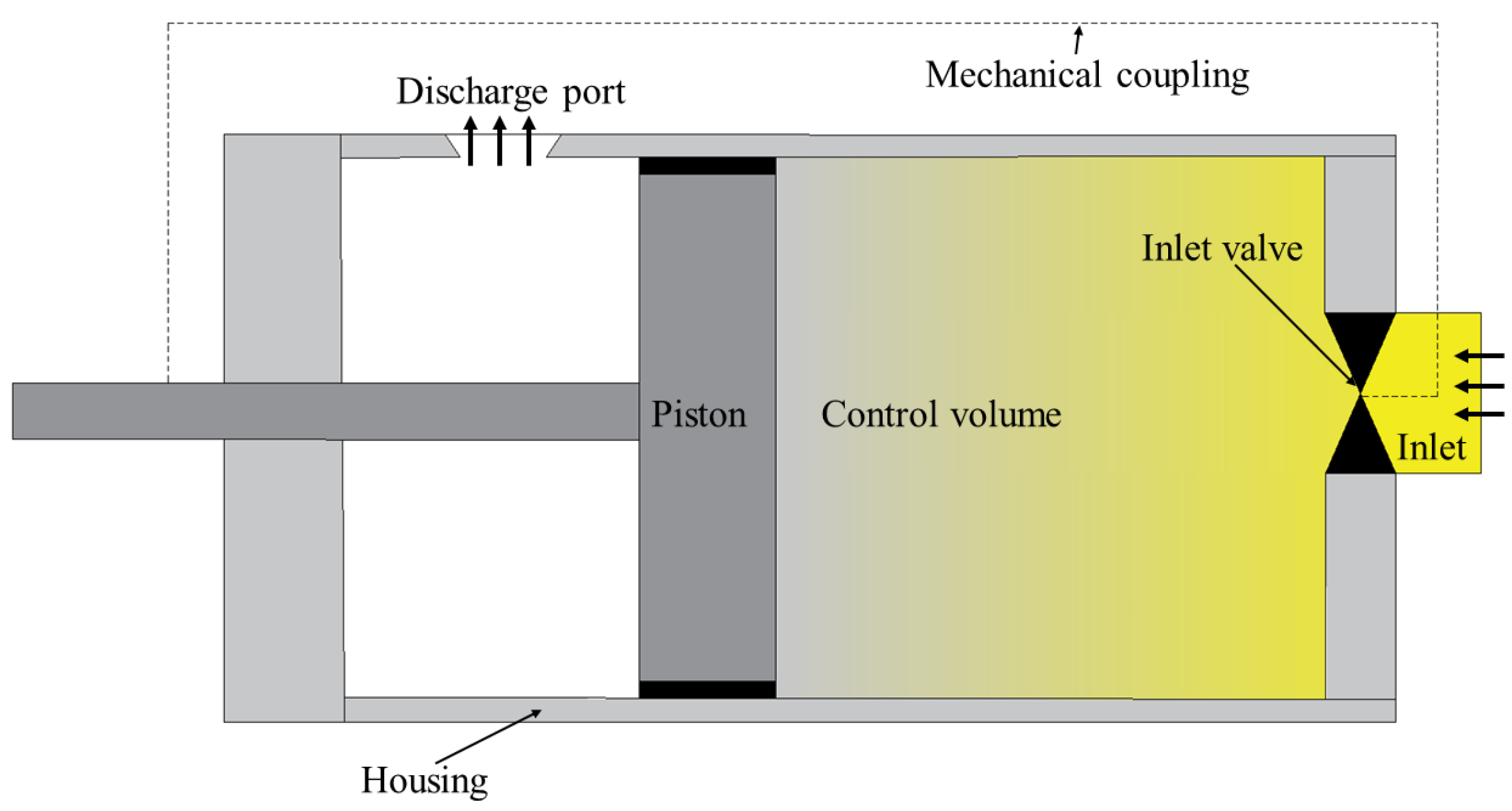
Figure 2.
Gas expander P–V diagram (a) cam-operated valve, and (b) externally controlled valve
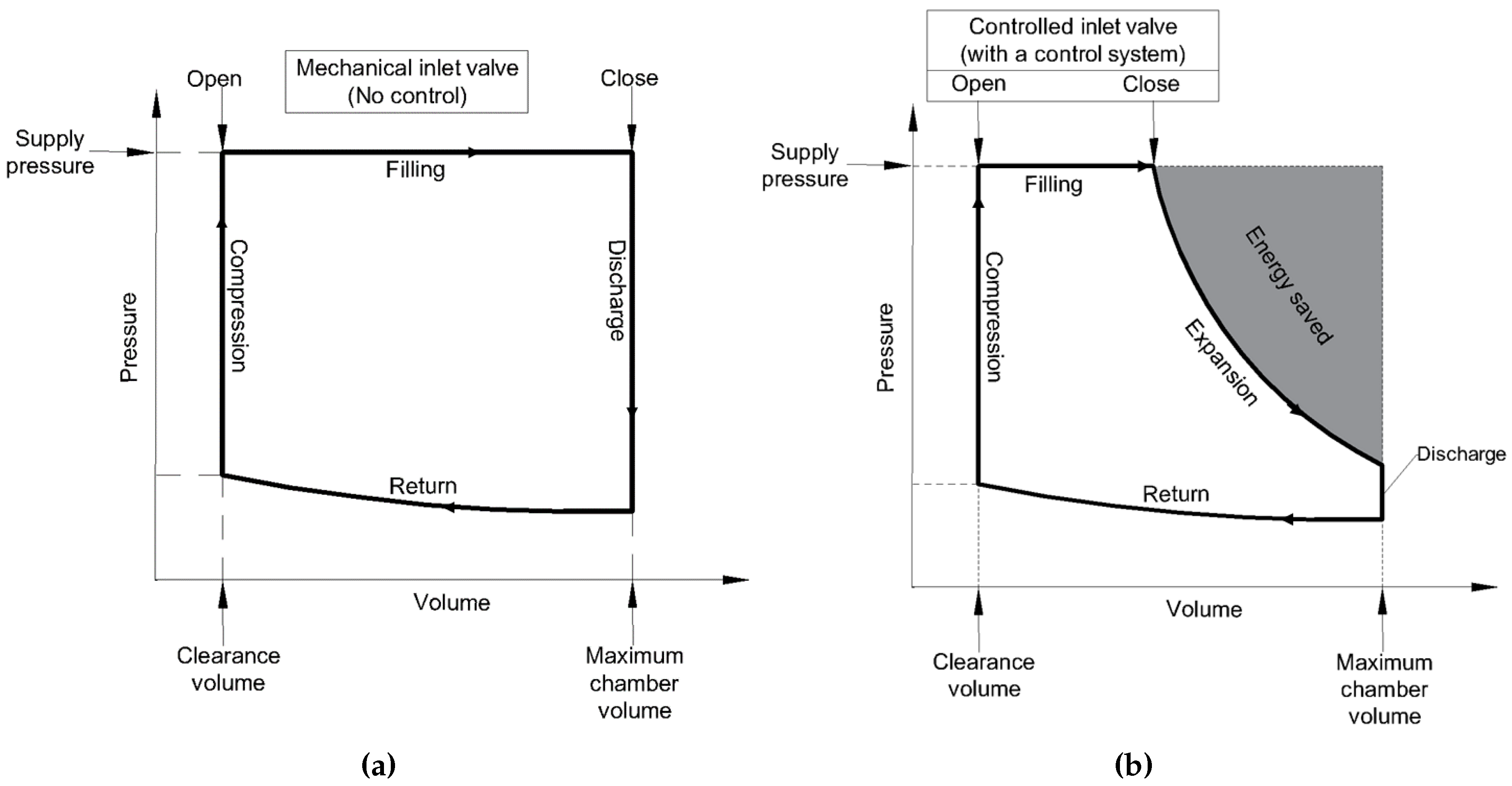
Figure 3.
Control valve types
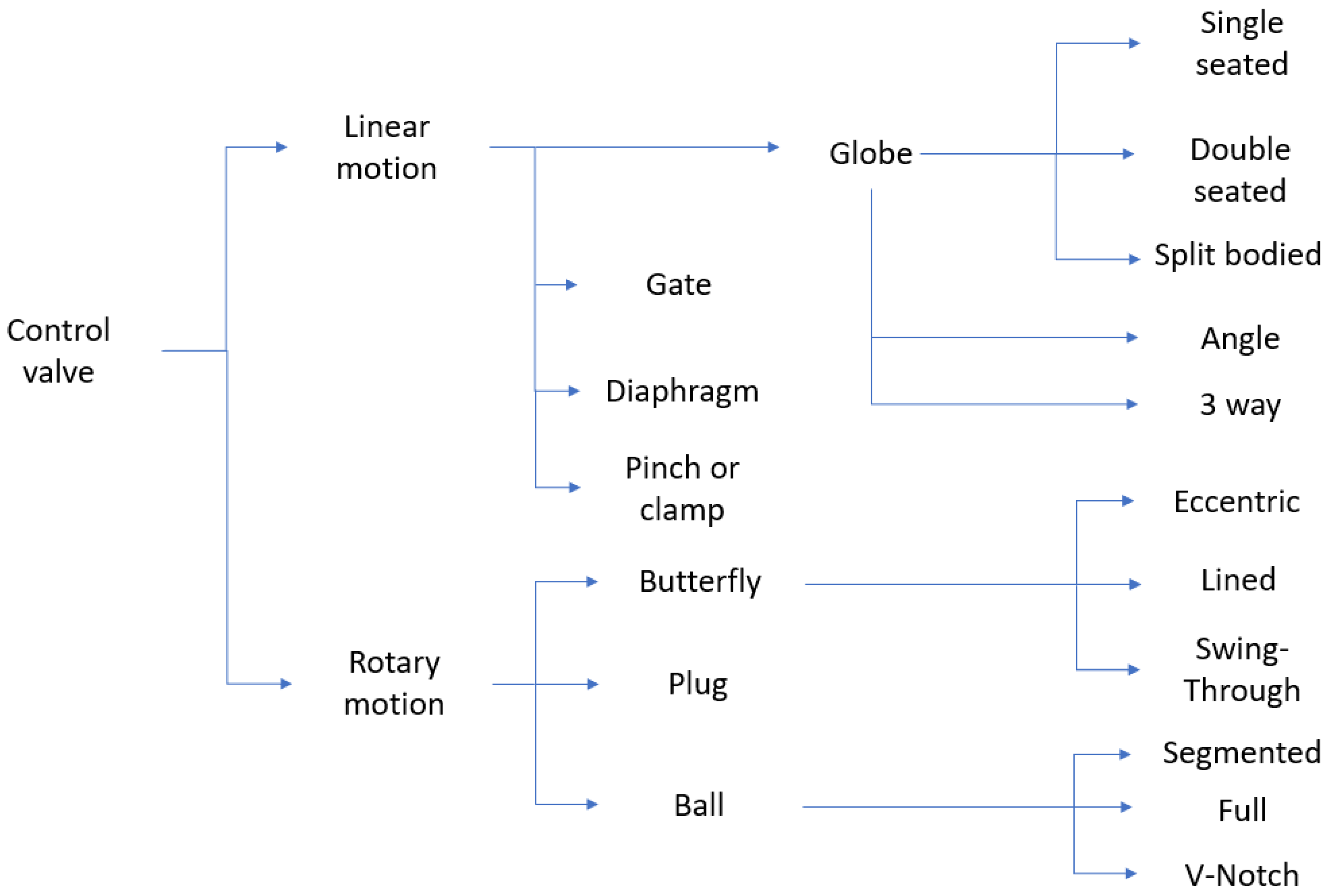
Figure 4.
SV system
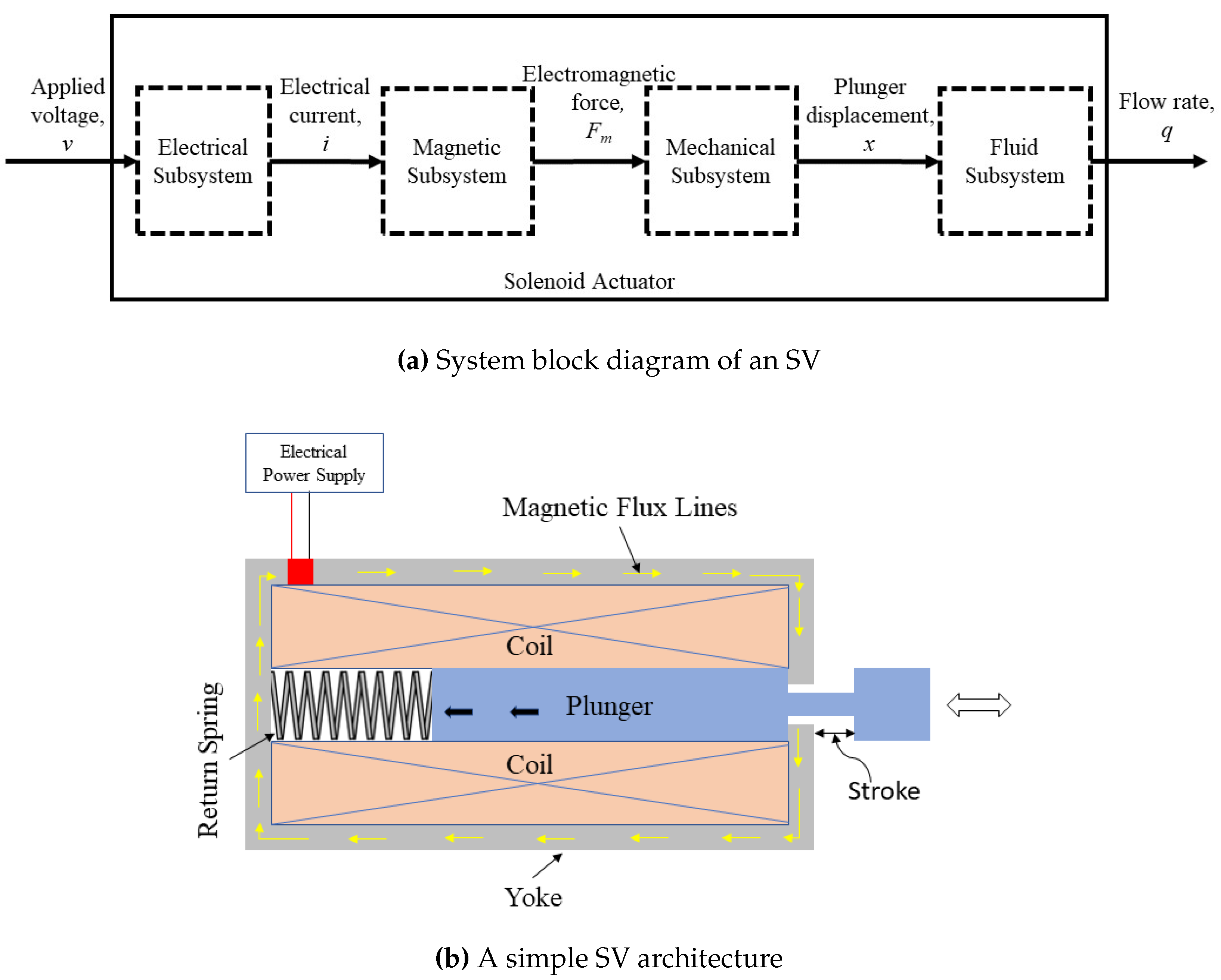
Figure 5.
Outline of an MoV
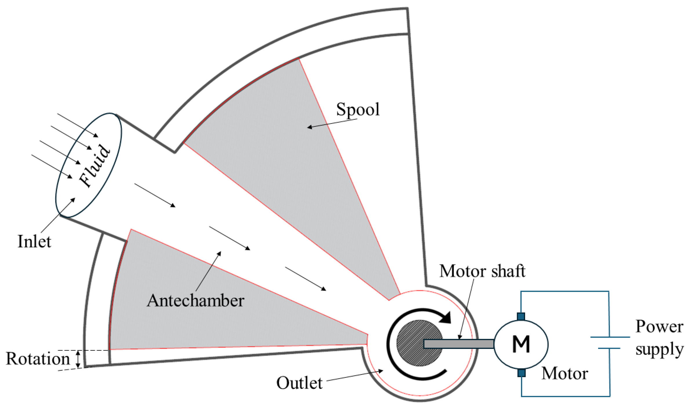
Figure 6.
An electro-hydraulic servo valve
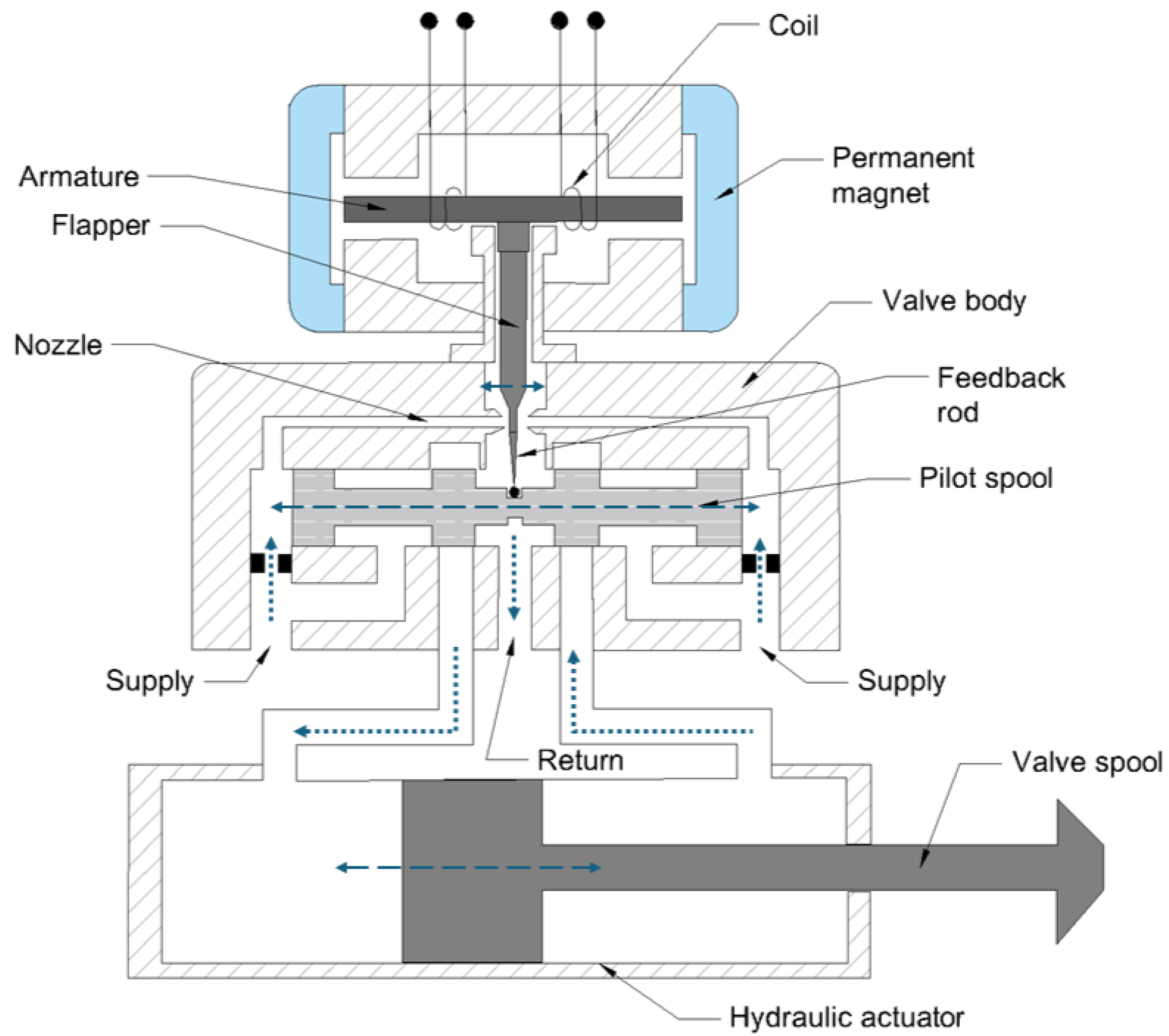
Figure 7.
PSV system
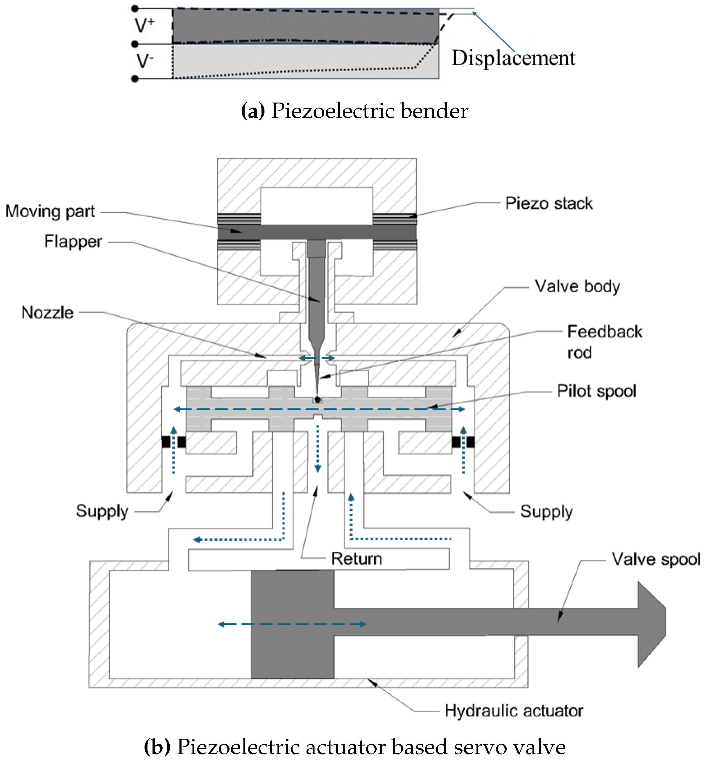
Figure 8.
Lumped parameter model of SV
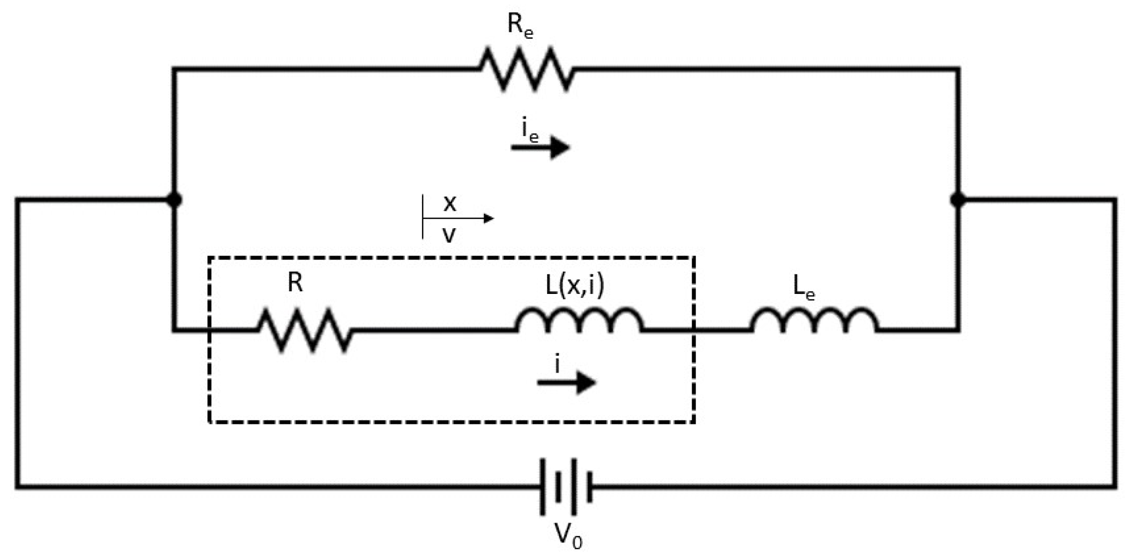
Figure 9.
Performance Comparisons between different SV models
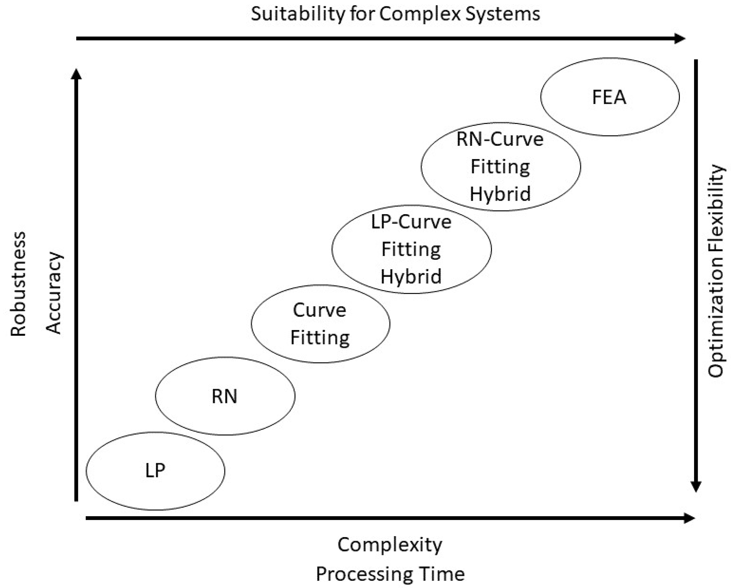
Figure 10.
GA schematic diagram
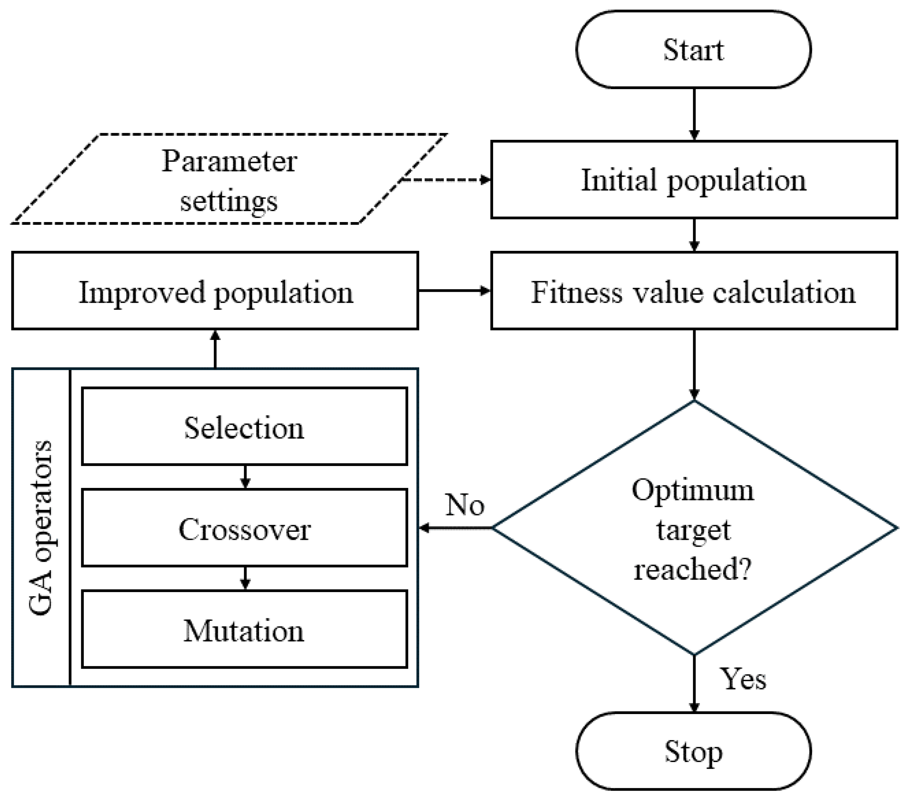
Figure 11.
PSO schematic diagram
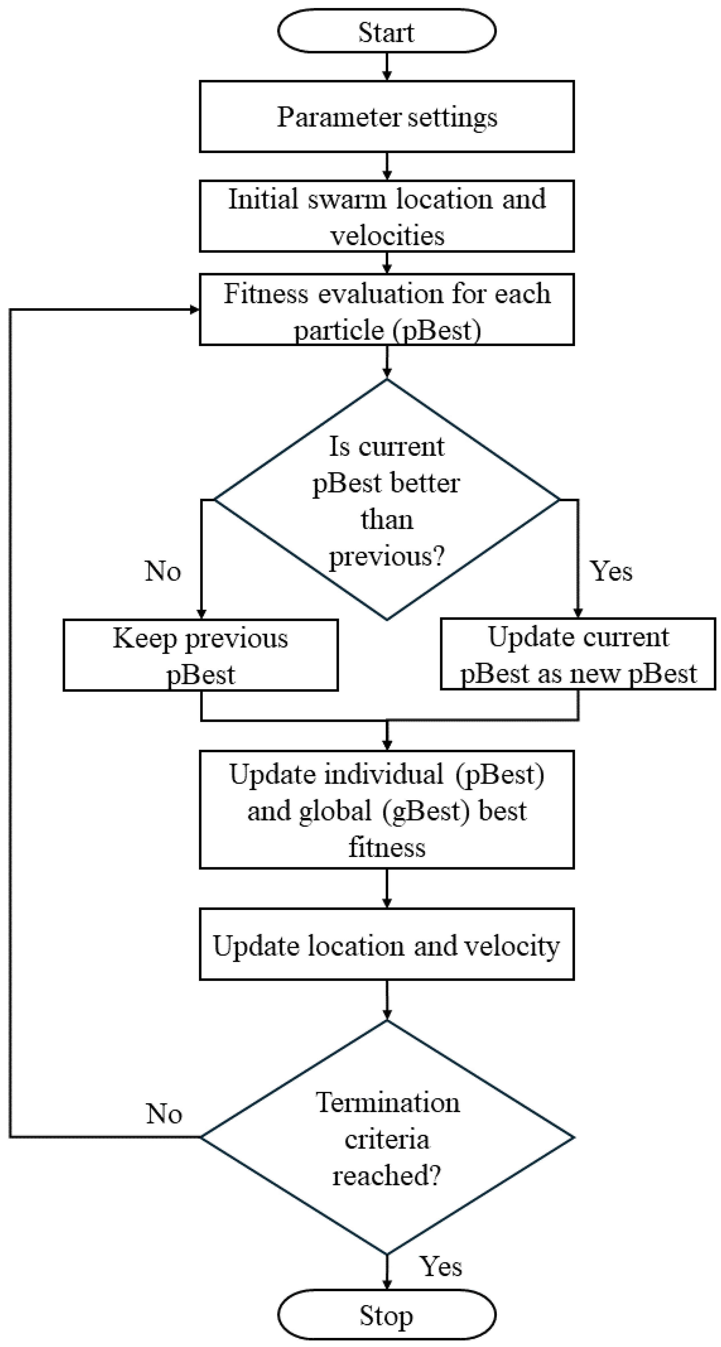

Table 1.
Summary of different types of valve actuators
| Type | Mechanism | Pros | Cons |
|---|---|---|---|
| Hydraulic | Pilot-operated [16,17,18] | Reliable, precise control, and high flow capacity | Slower response,complex architecture and costly manufacturing |
| Pressure-assisted [19] | Suitable for high-pressure systems, and reliable | Slower response, and complex mechanism | |
| Pneumatic | Pilot-operated [20] | High power-to-weight ratio, high flow rates, and reduced energy consumption | Sensitive to contaminants, and higher initial cost |
| Air-operated [21] | Simplicity, and lower installation cost | Slower actuation, and limited pressure handling capacity | |
| Electrical | Solenoid [10,22] | Faster response, simple control, and compact design | Limited pressure and flow capacity, sensitivity to voltage fluctuations, and heating and hysteresis effect |
| Motor [8,23,24] | High precision, and torque, simpler control, and suitable for high pressure systems | Higher energy consumption | |
| Piezoelectric [25,26] | Very fast and precise response with minimal power consumption | Limited force and stroke, requires displacement amplifiers, not suitable for high-pressure systems, and higher cost | |
| Hybrid | Electro-hydraulic [27,28,29,30,31] | High force, large pressure handling, high precision, and versatile architecture | Complex and maintenance-intensive design, and higher installation costs |
| Electro-pneumatic [32,33] | Fast response and precise control, and energy-efficient | Complex installation, and sensitivity to environmental conditions |
Table 2.
Recent innovative nature-inspired optimization techniques
| Name of the algorithm | Pros | Cons |
|---|---|---|
| Electric eel foraging optimization (EEFO) [111] | High searching efficiency, simplicity, scalability, robustness, and ease of implementation | Less effective in discrete optimization problems, and unable to achieve a quasi-optimal solution close to the global optimum for certain problems |
| Multi-Objective boxing match algorithm (MOBMA) [112] | High convergence rate and effective for complex problems with multiple objectives | Requires incorporation of other learning algorithms for better performance |
| Young’s double-slit experiment (YDSE) optimizer [113] | Suited for multi-objective problems | Several parameters need to be tuned and require incorporation of other stochastic algorithms for faster convergence |
| Arithmetic optimization algorithm (AOA) [114] | Ability to escape local minima | This is an initial framework which should be enhanced according to the specific problems |
Table 3.
Summary of popular control techniques
| Name of the algorithm | Pros | Cons |
|---|---|---|
| PID [120] |
|
|
| KF [126,127,128] |
|
|
| SMC [42,74,95,129,131] |
|
|
| Backstepping [141,142,143] |
|
|
Disclaimer/Publisher’s Note: The statements, opinions and data contained in all publications are solely those of the individual author(s) and contributor(s) and not of MDPI and/or the editor(s). MDPI and/or the editor(s) disclaim responsibility for any injury to people or property resulting from any ideas, methods, instructions or products referred to in the content. |
© 2024 by the authors. Licensee MDPI, Basel, Switzerland. This article is an open access article distributed under the terms and conditions of the Creative Commons Attribution (CC BY) license (http://creativecommons.org/licenses/by/4.0/).
Copyright: This open access article is published under a Creative Commons CC BY 4.0 license, which permit the free download, distribution, and reuse, provided that the author and preprint are cited in any reuse.


