Submitted:
20 July 2024
Posted:
22 July 2024
You are already at the latest version
Abstract
Mechanical response of composite structures concerning also natural frequencies is a function of material and geometrical describing plates and shells. In the present paper the optimization of those parameters is demonstrated. It is based on the formulation that uses the key-points (spline functions) and evolutionary algorithms. The numerical solutions dealing with the optimal design of axisymmetric cylindrical shells having variable radius are presented and discussed in details.
Keywords:
Shape optimization
; Functionally graded materials
; Cylindrical shells
; Eigen-frequencies
1. Introduction
Historically, eigenfrequencies of cylindrical shells were determined by Rayleigh in 1877 (an infinite isotropic shells), Love [1] (free ends of a finite length shell) and then Koga [2] solved problems of forty five combinations of boundary conditions. Fischer [3] extended the method of Koga to circular shells of composite materials which are specially orthotropic. Shao et al. [4] studied free vibrations of laminated open cylindrical shells with arbitrary boundary conditions.
Structures (beams, plates, shells) made of functionally graded materials (FGM) are composed of two metals or metal and ceramic or two polymers. The physical properties of FGM are usually controlled by the assumed law of variations in some direction. The new class of composite materials (FGM) has been also subjected to the various types of investigations [5,6,7,8,9].
Due to the possible variable porosity and thicknesses of FG structures eigenfrequencies can be controlled and optimized using the appropriate modeling of beams, plates and shells [10,11,12,13]. The cited studies deals mainly with the analysis of so-called axially FG (AFG) materials.
For a such class of materials free vibrations of cylindrical shells are identified by the effects of different parameters, i.e. the thickness, ratio of the internal radius to the mean (or the external) radius and boundary conditions.
In the present paper the shape optimization problems of cylinders are considered. The aim of optimization is to maximize eigenfrequencies of structures varying the cylindrical thickness/shell radius of curvature along the longitudinal direction (AFGMs).
2. Governing Relations
The total energy of the shell is given by:
The strain energy U is defined in the classical way, i.e.:
whereas the kinetic energy of the shell structure is defined in the following way:
For cylindrical shells the curvilinear coordinates ξ1, ξ2, and ξ3 correspond to the longitudinal (x), circumferential (Rθ) and normal coordinate (z) to the mid-surface, respectively. R means the radius of the cylinder. The symbol τ denotes the physical time and ρ is the shell density variable with the shell thickness z for structures made of FGMs.
The relationship between stresses σij and strains εij can be written as follows:
For FGM materials considering the thickness stretching the stiffness matrix components Qij are 3D relations given by:
The elastic modulus E variation characterizes the distribution of porosity along the thickness direction z and is defined in the following way:
where the symbols t and b refer to the material properties on top and bottom surfaces, n is power index. ν (const) is the Poissons ratio.
The explicit form of the strain components εij can be expressed in different form as it is discussed by Muc et al. [14]. Using the Love-Kirchhoff hypothesis the strain components can be expressed as follows:
Aγ mean the Lame coefficients in 2-D curvilinear orthogonal system of coordinates (ξ1, ξ2). The strain components ε22 can be obtained by the cyclic permutation of the subscripts 1, 2 and 3.
3. Definition of Design Variables
Optimal design of composite cylindrical shells can be carried in different ways and it depends on the definition of design variables. Therefore, in this area we can distinguish the following approaches:
- The radius of the cylindrical shell R can vary both in the longitudinal x and circumferential directions θ and it introduces the new type of design variable connected with the shape optimization problems (a variable shell mid-surface– Figure 3) – see the problems formulated for laminated shells in Ref [18]
The shown above possible definitions of design variables demonstrate the possible optimization problems of maximization (minimization) of eigen-frequencies with respect to different design variables.
The solution of optimization problems can be found with the use of the appropriate optimization algorithms. In our case of the shape optimization problem we propose to apply the evolutionary algorithm method described in details in Ref. [19,20]. However, let us note that the fundamental set of equations derived with use of the Euler method from the functional (1) is nonlinear due to the form of the design variables.
4. Shape Optimization of the Shell Mid-Surface for Axi-Symmetric Cylinders
Very few papers concern the issues of optimization of the mid-surface shape for vibrating rotationally symmetrical or prismatic shells - see [21,22]. This is due to the fact that less attention has been paid to the characteristics of the dynamic response of structures to date, and more to their behavior under the influence of static loads.
The tasks of optimizing the shape of the middle surface of a structure are most often associated with the objective of optimizing the thickness. Due to this fact, various optimization problems can be formulated, consisting of (cf. Barbosa et al. [22] ):
- the demand to meet the condition of a constant value of the volume enclosed by the rotationally symmetric shell - then the thickness of the shell is assumed to be constant,
- the requirement to meet the condition that the volume occupied by the shell material is constant - this corresponds to the condition of the structure weight invariability during the optimization process (the shell wall thickness may change).
In this section, we will present a solution to the optimization problem consisting in the maximization of the lowest natural frequencies of the cylindrical shell. The design variables are the radius R (x) values of the rotationally symmetric shell at the control points. We impose limitations on possible changes in the radius values in the form:
where R0 is the radius of the cylindrical shell. The curve Γ defining the shape of the longitudinal line of the shell is determined by specifying pairs of values (x, R (x)) where x is the coordinate of the control point along the length of the forming shell - see Figure 3. The optimization problem was solved using a modified evolutionary strategy (ZSE) introducing five control points. Additionally, due to the symmetry of the problem, a condition was imposed on the concatenated functions in the form of the derivative value of the R (x) function at the point x5. The natural frequencies are derived with the use of FE method varying also the wave number in the circumferential direction
In the analyzed numerical example, the case of a restrained cylindrical shell with geometrical and mechanical properties was considered. The aim of the considerations is to determine: (i) the optimal shape for isotropic shells, (ii) the influence of orthotropy on the optimal shape, (iii) the influence of the FGM characteristics on the optimal design.
The results of the numerical calculations are presented in Table 1. The optimal shape of the Γ curve describing the surface of the middle rotation-symmetric shell is identical for the isotropic and orthotropic material. However, in the case of an orthotropic material, the lower Young’s modulus corresponds to the longitudinal direction, and the Young’s modulus in the circumferential direction is identical for both types of materials. Due to the form of natural vibrations (vibrations in the circumferential direction are dominant), the identical Young’s modulus in this direction results in the obtained identical shapes of the curve Γ. Various material properties in the longitudinal direction have a fundamental influence on the form of natural vibrations. It also causes some changes in the percentages determining the increase of the lowest natural frequency for the optimal shapes of the center surface of the rotationally symmetric shell.
The increase in the frequency of critical vibrations is primarily caused by the allowable increase in the shell radius. The obtained value of the increment may seem large, but it is a typical increment for this type of task,
References
- Love, A.E.H. On the small free vibrations and deformations of a thin elastic shells. Phil. Trans. Roy. Soc. 1988, 179A, 491–546. [Google Scholar]
- Koga, T. Effects of boundary conditions on the free vibrations of circular cylindrical shells. AIAA J 1988, 26, 1387–1386. [Google Scholar] [CrossRef]
- Fischer, C.A. On the free vibrations of a circular cylindrical shells composed of a composite materials, MME Thesis, Univ. Delaware, 1992.
- Shao, D.; Wang, Q.; Qin, B. A simple first order shear deformation shell theory for vibration analysis of composite laminated open cylindrical shells with general boundary conditions, Compos. Struct. 2018, 184, 211–232. [Google Scholar]
- Khayat, M.; Dehghan, S.M.; Najatgholipour, M.; Baghiani, A. Free vibration analysis of functionally graded cylindrical shell with different shell theories using semi-analytical method, Steel Comp. Struct. 2018, 28, 735–748. [Google Scholar]
- Loy, C.T.; Lam, K.Y.; Reddy, J.N. Vibration of functionally graded cylindrical shells. Int J Mech Sci. 1999, 41, 309–324. [Google Scholar] [CrossRef]
- Pradham, S.C.; Loy, C.T.; Lam, K.Y.; Reddy, J.N. Vibration characteristics of functionally graded cylindrical shells under various boundary conditions, Appl. Acoust. 2000, 61, 111–129. [Google Scholar] [CrossRef]
- Yang, J.; Shen, H.S. Free vibrations and parametric resonance of shear deformable functionally graded cylindrical panels, J. Sound Vibr. 2003, 261, 871–893. [Google Scholar] [CrossRef]
- Arshad, S.H.; Naeem, N.M.; Sultana, N. Frequency analysis of functionally graded material shells with various volume fraction laws, Proc. IMechEng., Part C, J. Mech. Eng. Sc. 2007, 221, 1483–1495. [Google Scholar] [CrossRef]
- Cao, D.X.; Gao, Y.H.; Yao, M.H.; Zhang, W. Free vibration of axially functionally graded beams using the asymptotic development method. Eng. Struct. 2018, 173, 442–448. [Google Scholar] [CrossRef]
- Huang, Y.; Li, X.F. A new approach for free vibration of axially functionally graded beams with non-uniform cross-section. J. Sound Vib. 2010, 329, 2291–2303. [Google Scholar] [CrossRef]
- Ruocco, E.; Zhang, H.; Wang, C.M. Buckling and vibration analysis of nonlocal axially functionally graded nanobeams based on hencky-bar chain model. Appl. Math. Modelling 2019, 63, 445–463. [Google Scholar] [CrossRef]
- Wei, J.; Song, Z.; Li, F. Superior aeroelastic behaviors of axially functional graded cylindrical shells in supersonic airflow. Journal of Fluids and Structures 2020, 96, 103027. [Google Scholar] [CrossRef]
- Muc, A.; Kubis, S. ; Bratek, Ł, Muc-Wierzgoń, M. Higher Order Theories for the Buckling and Post-buckling Studies of Shallow Spherical Shells made of Functionally Graded Materials, Composite Struct. 2022.
- Muc, A. Optimizing the Thickness/Stiffness Distribution Optimization of Infinitely Wide Porous FGM Plates subjected to Supersonic Flutter Constraints, Mech. Composite Mater. 2021, 56, 713–720. [Google Scholar] [CrossRef]
- Flis, J.; Muc, A. Influence of Coupling Effects on Analytical Solutions of Functionally Graded (FG) Spherical Shells of Revolution, Rev. Appl.Mat.Science 2021, 60, 761–770. [Google Scholar]
- Muc, A.; Muc-Wierzgoń, M. Effects of Material Constructions on Supersonic Flutter Characteristics for Composite Rectangular Plates Reinforced with Carbon Nano-structures, Sci. Eng. Compos. Mater. 2021, 28, 107–115. [Google Scholar] [CrossRef]
- Muc, A. ; Optimal design of composite multilayered plated and shell structures (2007) Thin-Walled Structures 2007, 45, 816–820.
- Muc, A. ; An Evolution Strategy in Structural Shape Optimization Problems for Plates and Shells, Proceedings WCSMO-6, Rio de Janeiro, 2005.
- Muc, A. Evolutionary design of engineering constructions (2018) Latin American Journal of Solids and Structures 2018, 15, art. no. e87, 21 p. [CrossRef]
- Hinton, E.; Ozakca, M.; Rao, N.V.R. Free Vibration Analysis and Shape Optiization of Variable Thickness Prismatic Folded Plates and Curved Shells, Part 2: Shape Optimization, Journal of Sound and Vibration 1998, 181, 567–581.
- Barbosa, J.I.; Mota Soares, C.M.; Mota Soares, C.A. ; Sensitivity Analysis and Shape Optimal design of Axisymmetric Shell Structures, Comput. Syst. Eng. 1991, 2, 525–534. [Google Scholar]
Figure 1.
Shell wall construction for the uniform thickness t(ξ1, ξ2, ξ3)=t: a) uniform distribution of pores, b) symmetric distribution, c) unsymmetric distributions.
Figure 1.
Shell wall construction for the uniform thickness t(ξ1, ξ2, ξ3)=t: a) uniform distribution of pores, b) symmetric distribution, c) unsymmetric distributions.
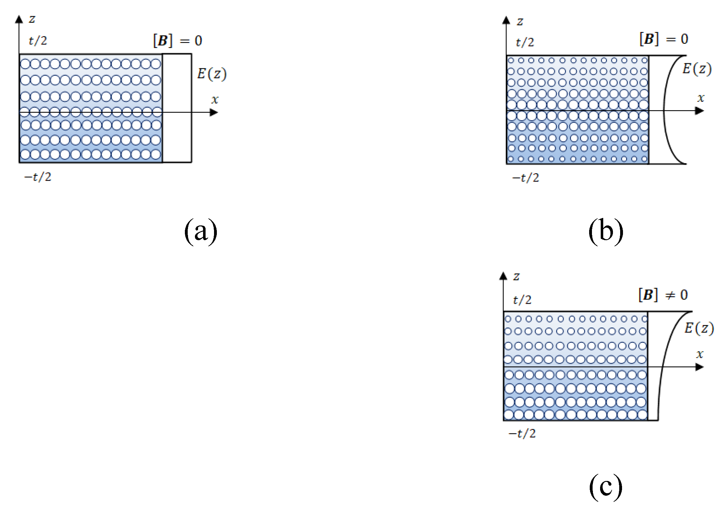
Figure 2.
Variations of the shell thickness in the x directions.
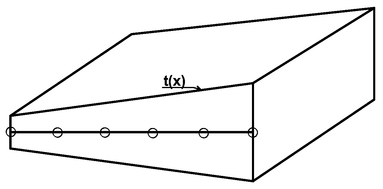
Figure 3.
Variable shell mid-surface.
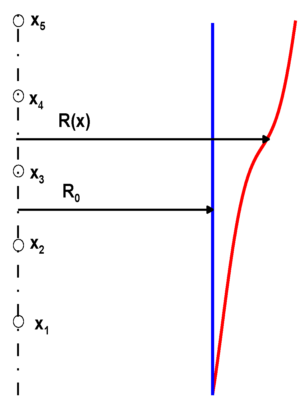

Table 1.
Locations of control points for the optimal shape of the curve Γ characterizing the shape of the central surface and the obtained percentage.
Table 1.
Locations of control points for the optimal shape of the curve Γ characterizing the shape of the central surface and the obtained percentage.
| Values of dimensionless control points x/L | R(xi)/R0 Isotropic and cross-ply laminated shells |
R(xi)/R0 Functionally Graded Material Et/Eb=3, n=5 |
| 0.1 | 1.028 | 1.015 |
| 0.2 | 1.072 | 1.043 |
| 0.3 | 1.108 | 1.084 |
| 0.4 | 1.121 | 1.091 |
| 0.5 | 1.126 | 1.094 |
|
100% ωopt/ωcyl |
227.7 | 193.5 |
Disclaimer/Publisher’s Note: The statements, opinions and data contained in all publications are solely those of the individual author(s) and contributor(s) and not of MDPI and/or the editor(s). MDPI and/or the editor(s) disclaim responsibility for any injury to people or property resulting from any ideas, methods, instructions or products referred to in the content. |
© 2024 by the authors. Licensee MDPI, Basel, Switzerland. This article is an open access article distributed under the terms and conditions of the Creative Commons Attribution (CC BY) license (http://creativecommons.org/licenses/by/4.0/).
Copyright: This open access article is published under a Creative Commons CC BY 4.0 license, which permit the free download, distribution, and reuse, provided that the author and preprint are cited in any reuse.


