Submitted:
07 September 2025
Posted:
08 September 2025
You are already at the latest version
Abstract
The paper presents a methodology for the passive and active displacement and vibration damping of beams and multilayered composite cylindrical shells. The displacement suppression systems consist of piezoelectric extension actuators bonded to the external surface. The second solution applies piezoelectric shear actuators/sensors embedded in the structure, An analysis on active vibration control of smart laminated cylindrical shells based on Hamilton’s principle and the higher order deformation theory is discussed. Then, the investigated cylindrical structure is modelled using two different approaches: solutions with the aid of series with the use of numerical symbolic package Mathematica and finite element NISA II models. Active vibration suppression is implemented with positive position feedback (PPF) and velocity feedback. The non-local formulation shows the influence of governing relations on eigenfrequencies. The effects of the position of the piezoelectric actuators on shell structures is demonstrated .
Keywords:
laminated beams
; laminated cylindrical panels
; active vibration control
; passive displacement control
; extension actuators
; shear actuators
; optimization problems
1. Introduction
Intelligent materials with multifield coupling properties become an important aspect of modern science and technology with applications in many industrial fields such as biomedical, electronic and mechanical engineering. The concept involves combined sensing, actuation and control capabilities embedded within materials and structures at different scales [1,2].
The subject of the analysis is connected with the variety of problems that due to the lack of space are given in the very shortened form: 1) the type of the material – multilayered composites, piezoelectrics, functionally graded materials, nanostructures, 2) the failure mode considered – static (buckling) or dynamic instabilities (divergence), free vibrations, 3) the form of PZT – extension actuators bonded to the surface or shear actuators/sensors embedded in the structure, 4) the form of the PZT control – passive or active, 5) the accuracy of the kinematical hypothesis used in the description – classical, first or higher order shear deformation theory.
As it may be seen from the above list of factors that may affect on the electromechanical behaviour of 2D smart structures the complex studies/ investigations do not exist in the open literature. Different researchers conduct analysis of the particular problems presented in the above list not going deeper insight the problems and not even trying to generalize various results.
Therefore, the fundamental research problems that we intend to solve in the paper can be formulated in the following way:
the determination of the most significant/important elements arising in the PZT vibration suppression for the considered 2D smart structures made of advanced materials.
the definition of the most suitable design variables that can be implemented in the optimal design.
The novelties introduced in the present work cannot be formulated only as the proposal of generalization of some results but they are also connected with the nonlinear description of unidirectional fibrous composites and nonlocal approach to problems dealing with nanostructures.
The present state of knowledge is illustrated by a series of works:
In the above list of publications more than 2000 references is presented and discussed so that it is impossible to demonstrate herein the review of the broader literature dealing with various aspects of the paper. The above list consists of four monographs and two review papers, not saying about research paper. The review of the cited literature illustrate evidently the necessity of carrying out the research and the lack of concise approach to design of 2D smart structures.
The present work intends to discuss and demonstrate a comprehensive methodology for the structural analysis and vibration suppression of 2D PZT- plated/shell constructions made of advanced materials. The subject of the analysis is connected with the form of PZT – extension actuators bonded to the surface or shear actuators/sensors embedded in the structure – Table 1.
2. Formulation of the Local Coupled Electro-Mechanical Problem
2.1. Kinematic Relations
The displacements Ũi(x,y,z) (i=1,2,3) at any point of the shell in the x, y and z directions, respectively, are expressed in the following form [46]:
Ũ1(x,y,z)=u(x,y)+zφ1+z2ψ1+z3γ1+z4θ1
Ũ2(x,y,z)=v(x,y)(1+z/R)+zφ2+z2ψ2+z3γ2+z4θ2 (1)
Ũ3(x,y,z)=w(x,y)+zχ1+z2 χ2+z3 χ3
where u, v, w are the displacements of a generic point on the reference mid-surface, R denotes the radius of the cylindrical panel, ϕ1, ϕ2 are the rotations of normal to the mid-surface about the y- and x-axes, respectively and χ1, χ2 and χ3 are three parameters characterizing the thickness stretching. Assuming that the transverse shear strains are equal to zero at the top and bottom of the shell surface the variables u(x,y), φ1, ψ1, γ1, θ1, v(x,y), φ2, ψ2, γ2, θ2 can be expressed as the linear functions of u, v, w, ϕ1, ϕ2, χ1, χ2 ,χ3. The in-plane displacement have been expanded to the 4-th order and to the 3-rd order in z. Further simplifications of the number of the kinematic variables are described in Table 2.
Based on the above expressions, the total, linear 3-D strain tensor can be written as follows:
εij(x,y,z)=0.5(ծŨi/ծxj+ ծŨj/ծxj),x1=x,x2=y,x3=z (2)
To the linear membrane terms the non-linear components are added in the following form:
ēxx=0.5(ծw/ծx)2,ēyy=0.5(ծw/ծy)2,ēxy=ծ2w/(ծxծy) (3)
Taking into account Eqs (1-3) the strain-displacement relations can be written in the following way – the explicit form is written in [44]:
[εij]=[ εij]0+z[κij](0)+ z2[κij](1)+ z3[κij](2)
i, j=1 or 2 or 3
dimension of matrices [6x1]
2.2. Constitutive Equations and Variational Formulation
Modelling of composite structures having smart piezoelectric sensors or actuators is very similar to that for conventional composite layered structures, however, there is one difference reflected in the constitutive laws in the form of the electromechanical coupling. It affects also the additional complexities in the FE formulation. The constitutive model for laminated panels with embedded piezoelectric sensors/actuators (S/A(s) (Figure 1) is established in the global cylindrical coordinate x-y-z system (x – a longitudinal direction, y – a circumferential direction, z – a normal direction to a shell mid-surface). It is given by:
[σ]=[C][ε] (4)
Dimension of matrices [9x1] =[9x9][1x9]
The symbols having the bar over them have the standard mechanical interpretation, i.e. stresses [σ] and strains [ε] – see Eq. (4). The coefficients in [Q] matrix can be calculated from the elastic moduli, Poisson’s ratios, piezoelectric moduli and dielectric constants of the lamina. [D] is the vector of electric displacements (three components), [e] is the matrix of piezoelectric coefficients of size 6x3, [μ] is the permittivity matrix of size 3x3 and [E] is the applied electric field. Its field is defined as the gradient of the electric potential Φel , i.e.: [E]=-grad Φel.
Φel(x,y,z)=φ0+φ1z/t, φ0=0.5(V++ V-) (5)
Through integrating along the plate/shell thickness z the membrane, bending stress and transverse shear stress resultants can be determined in the classical way.
Introducing the total potential energy of a typical element of the cylindrical panel given by the potential energy:
UL=0.5∫[[ε]Tr[C][ε]]Rdxdydz (6)
and the kinetic energy of the laminate:
T=0.5∫ρ{(∂u/∂τ)2+(∂v/∂τ)2+(∂w/∂τ)2+
z2(∂ψ1/∂τ)2+z2(∂ψ2/∂τ)2}Rdxdydz (7)
where Ω and ρ are the volume (the Cartesian product [0,Lx]x[0,Ly]x[-t/2,t/2]) and density of the laminated structures. Besides, the work done by the external thermo-mechanical loads on the panel (see Figure 1) is as follows [47]:
Wext=0.5∫{Nx0(∂w/∂)2+ Ny0 (∂w/∂y)2}Rdxdydz (8)
and the work of an electric force:
Wel=ʃ{qΦel+q(Φel-Φ*el) }Rdxdydz (9)
where the symbol q denotes the electric charge distributed over the surfaces (boundary electric conditions) and Φel denotes the electric potential.
Using Hamilton’s Principle:
δ{T-UL+Wext+Wel}=0 (10)
one can derive the fundamental system of equations describing the deformations of the structures. Let us notice that the above operations can be carried out in a symbolic way searching for the possible variations of unknown functions - u, v, w, ϕ1, ϕ2, χ1, χ2 ,χ3, Φel with the aid of the operation “Variational Calculus” that can be found in the package Mathematica. Finally, the variations of the Hamilton functional (16) leads to nine differential equations. The first two characterize the in-plane effects and are functions of in-plane displacements u and v. The next three describe bending and stretching effects and are directly connected with the description of the failure effects, and the last corresponds to the electric potential.
2.3. Non-Local Formulation
The above relations (1)-(10) corresponds to the classical (so-called local formulation). The non-local formulations can be included easily by adding differential operators.
3. Numerical Results
3.1. Active Vibration Control–Shear Actuator
Vibration suppression is a concept that is well suited for an intelligent structure because of its ability to sense and respond to external stimulus. The active vibration suppression uses sensors and actuators to control the response of the system Figure 2.
The system shown in Figure 2 is a closed-loop feedback control system since the signal sent to the actuator is a direct result of the incoming sensor signal.
The structure/compensator interaction is as follows (PPF positive position feedback – see Ref. [52]):
the structure:ξ’’+2ζωnξ’+ωn2ξ=-G ωc2η
the compensator: η’’+2 ζcωcη’+ωc2η= ωc2ξ’ (11)
where ξ is the modal coordinate, ηis the compensator coordinate, ζ is the damping ratio of the structure, ωn is the natural frequency of the structure, ζc is the compensator damping ratio, ωc is the compensator frequency and G is a scalar gain.
There are really three quantities that must be appropriately chosen to implement this feedback control: the scalar gain, the compensator natural frequency and the compensator damping ratio. The rest of the quantities are a direct result of the physical system.
To verify the correctness of the present FE computations the vibration modes and the damping properties were compared with the example shown in Ref. [53]. An infinite cylindrical shell was analyzed loaded by a harmonic distributed load (along the shell circumference γ) of the following form:
q(γ,τ)=q0sin(2(γ+γ0))eiωτ (12)
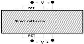
The shell is composed of four composite layers (FRP) oriented at 00 along the circumference and two PZT layers – see Figure 4. The extent of the shell is 900 (i.e. in Eq.(4) γ0 =450 and γě[-450,450]
The shell radius R=250 mm. The thicknesses of individual composite layers are equal to 0.2h, whereas PZT layers 0.15h and 0.05h. The mechanical properties of the used materials are following: PZT – E1=111 [Gpa], E2=E3=121 [Gpa], ρ=7750 [kg/m3] and composites – E1=183.4 [Gpa], E2=E3=11.7 [Gpa], ρ=1590 [kg/m3]. Others material constants, used herein, can be found in [53].
In Ref. [53] the authors computed the vibration modes using 3D FE discretization available in the ABAQUS code. In our approach the calculations were carried out with the use of the NISA II package and the structure (Figure 3) was modelled by plane and 3D FE. For the first nine vibration modes the results are demonstrated in Table 3. The agreement is very good, both for different FE codes and plane and 3D formulations. The modes of vibrations are different: bending along the circumference (the number of waves is different), out of plane modes and the thickness shear mode (the fifth).
Figure 3.
Cross-section of a cylindrical panel with PZT layers.
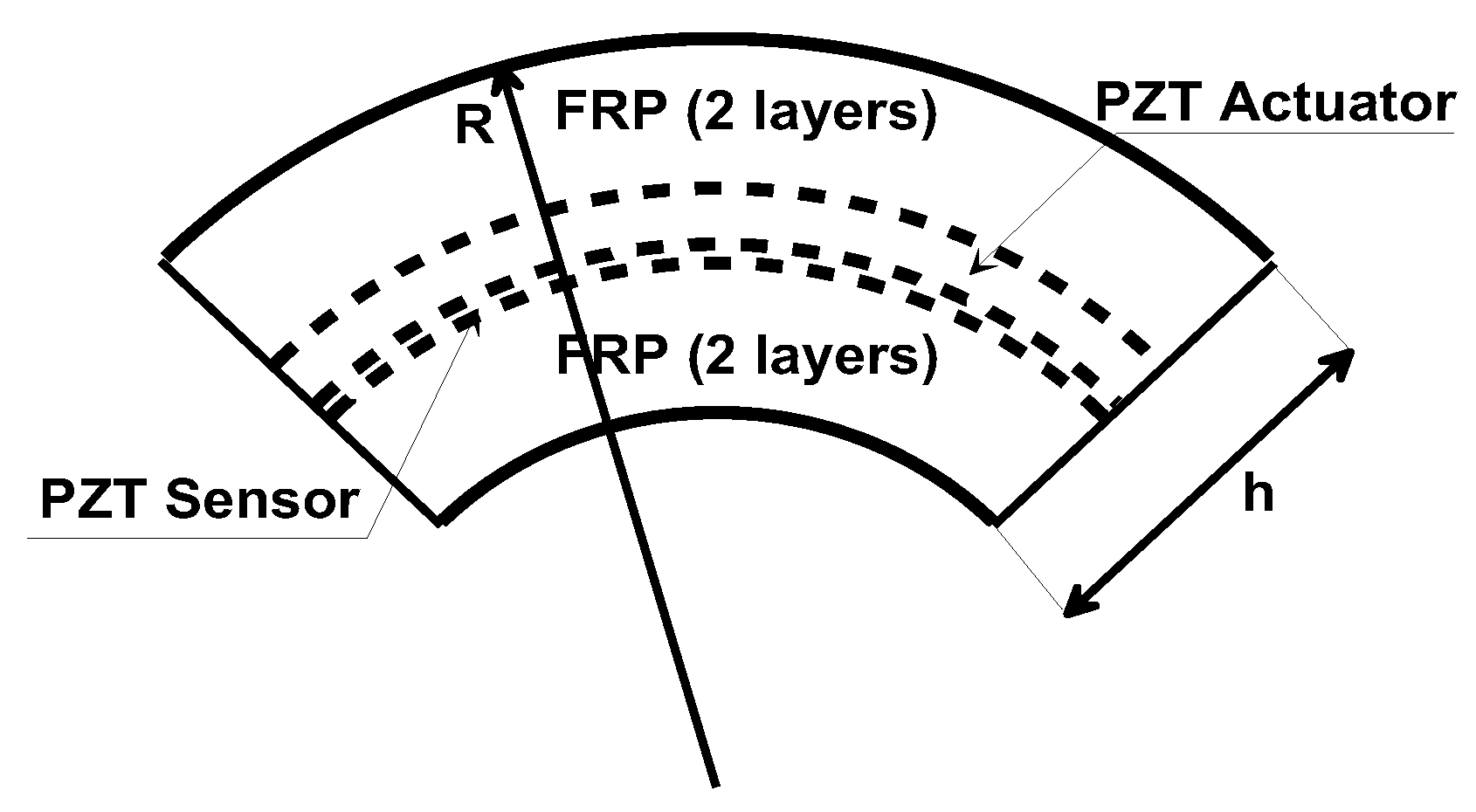
The two electrical boundary conditions are prescribed at r = R – h and R in the sense that the top and bottom surfaces are electrically closed, i.e. Φel=0 – see Eq. (6).
A controller is employed for active vibration suppression. The second order PPF controller is forced by the electric potential of the sensor at γ = 0. The feedback voltage (evaluated from the sensor and compensator relations (12)) is applied to the PZT-5A actuator layer. For a given choice of control parameters ωc, ζc and G – Eq. (11), the steady-state response of the system is computed for a given forcing frequency ω. The magnitude and phase of the radial deflection is plotted as function of the forcing frequency ω for different controller parameters to obtain frequency response curves – Figure 4.
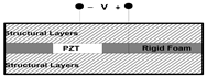
3.2. Smart Beam Structure – Extension Actuator
The use of passive actuators affects on the structural behaviour. In Ref. [55] the authors studied the behaviour of aluminium beam subjected to the action of actuators and sensors – Figure 5. The results given in Table 4 demonstrates a very good agreement between the ANSYS and NISA II analysis. The reduction of fundamental frequency reaches 97%.
The plotted results were evaluated with the use of the NISA II FE numerical package for the first critical frequency presented in Table 2. They are similar to those derived in Ref. [53]. However the author of the cited work calculated the results in an analytical, symbolic way (the Mathematica pack).
3.3. Location of Passive Actuators
Their influence of the position of sensors/actuators can be determined with the use of the optimal design procedures. For the passive reduction of normal displacements the positions of the PZT layers significant – see Figure 6, although the values of the resultant displacements are changed. Figure 6 represents the influence of the passive actuator located at the middle of the cylindrical panel. The normal displacements are reduced as the PZT actuators are bounded to the ends of the panel – Figure 6. Those problems can be solved with the use of the evolutionary algorithms [55].
The plots drawn In Figure 6 were obtained with the use of NISA II FE package and 3D finite elements.
4. Non-Local Formulation
The influence of employing the non-local formulations is shown in Figure 7. Similarly as for free vibrations the use of the stress gradient theory [56] decreases values of frequencies ω (in the comparison to the classical theories), whereas the strain gradient theory [57] have opposite effects. The magnitude of the growth/decrease is a function of the length scale parameters The use of the Mindlin theory [58] does not change values of frequencies since. In general, the Mindlin model, unifies the gradient elasticity theories of Eringen and Aifantis. Let us note that different branches (modes) of the solution can be plotted in plots ω-s for different values of n.
The formulation of the different non-local theories is presented and discussed in Ref. [30].
5. Concluding Remarks
The present paper presents a variety of the numerical results dealing with the influence of the formulation of governing relations on the vibration/displacements
suppression of cylindrical panels having PZT layers. The general formulation with the use the Hamilton’s principle for higher order 2D theories is discussed.
Various results are presented and solved:
- Local formulation and shear vibration control.
- Local formulation and extension displacement control.
- Non-local vibration control.
The conducted with the use of the Mathematica package and the NISA II commercial package demonstrate a very good agreement with the results shown in the literature.
References
- Crawley, E.F. and Luis, J., Use of piezoelectric actuators as elements of intelligent structures, AIAA Journal, Vol.25, 1987, pp.1373–1385.
- Zappino, E.; Carrera, E. Advanced modeling of embedded piezo-electric transducers for the health-monitoring of layered structures. Int. J. Smart Nano Mater. 2020, 11, 325–342. [Google Scholar] [CrossRef]
- Reddy, J. On laminated composite plates with integrated sensors and actuators. Eng. Struct. 1999, 21, 568–593. [Google Scholar] [CrossRef]
- Tzou, H.; Gadre, M. Theoretical analysis of a multi-layered thin shell coupled with piezoelectric shell actuators for distributed vibration controls. J. Sound Vib. 1989, 132, 433–450. [Google Scholar] [CrossRef]
- Arefi, M. , Smart analysis of doubly curved piezoelectric nano shells: Electrical and mechanical buckling analysis, Smart Structures and Systems, Vol.25,2020, pp.471-486.
- Mousavi, M. , Mohammadimehr, M. and Rostami, R., Analytical solution for buckling analysis of micro sandwich hollow circular plate, Computers and Concrete, Vol.24, 2019,pp.185-192.
- Farrokhian, A. , Buckling response of smart plates reinforced by nanoparticles utilizing analytical method, Steel and Composite Structures, Vol.35,2020,pp.1-12.
- Moosazadeh, H. and Mohammadi, M.M., Two-dimensional curved panel vibration and flutter analysis in the frequency and time domain under thermal and in-plane load, Advances in Aircraft and Spacecraft Science, Vol.8,2021, pp.345-372.
- Gharaei, A. , Rabieyan-Najafabadi, H., Nejatbakhsh, H. and Ghasemi, A.R., An analytical approach for aeroelastic analysis of tail flutter, Advances in Computational Design, Vol.7, 2022, pp.69-79.
- Atabakhshian, V. and Shooshtaria, A., A study on the dynamic instabilities of a smart embedded micro-shell induced by a pulsating flow: A nonlocal piezoelastic approach, Advances in Nano Research, Vol.9,2020, pp.133-145.
- Muc, A.; Flis, J.; Augustyn, M. Optimal Design of Plated/Shell Structures under Flutter Constraints—A Literature Review. Materials 2019, 12, 4215. [Google Scholar] [CrossRef]
- Muc, A.; Flis, J. Free vibrations and supersonic flutter of multilayered laminated cylindrical panels. Compos. Struct. 2020, 246. [Google Scholar] [CrossRef]
- Shu, X. Free vibration of laminated piezoelectric composite plates based on an accurate theory. Compos. Struct. 2005, 67, 375–382. [Google Scholar] [CrossRef]
- Zhang, P. , Qi, C., Fang, H. and Sun, X., Bending and free vibration analysis of laminated piezoelectric composite plates, Structural Engineering and Mechanics, Vol.75, 2020, pp.747-769.
- Arefi, M. and Meskini, M., Application of hyperbolic shear deformation theory to free vibration analysis of functionally graded porous plate with piezoelectric face-sheets, Structural Engineering and Mechanics, Vol. 71, 2019, pp. 459-467.
- Singh, A. and Kumari, P., Analytical free vibration solution for angle-ply piezolaminated plate under cylindrical bending: A piezo-elasticity approach, Advances in Computational Design, Vol.5, 2020, pp. 55-89.
- Zenkour, A.M. and Hafed, Z.S., Bending response of functionally graded piezoelectric plates using a two-variable shear deformation theory, Advances in Aircraft and Spacecraft Science, Vol. 7,2020, pp. 115-134.
- Dehsaraji, M.L. , Saidi, A.R. and Mohammadi, M., Bending analysis of thick functionally graded piezoelectric rectangular plates using higher-order shear and normal deformable plate theory, Structural Engineering and Mechanics, Vol.73,2020, pp. 256-269.
- Ridha, A.A. , Basima, S.K., Kareem, M.R., Raad, M.F. and Nadhim M.F., Investigating dynamic response of nonlocal functionally graded porous piezoelectric plates in thermal environment, Steel and Composite Structures, Vol. 40, 2021, pp. 243-254.
- Heidari, F. , Afsari, A. and Janghorban, M., Several models for bending and buckling behaviors of FG-CNTRCs with piezoelectric layers including size effects, Advances in Nano Research,Vol.9, 2020, pp.193-210.
- Taherifar, R. , Mahmoudi, M., Nasr Esfahani, M.H., Khuzani, N.A., Nasr Esfahani, S. and Chinaei, F., Buckling analysis of concrete plates reinforced by piezoelectric nano-particles, Computers and Concrete, Vol.23, 2019, pp. 295-301.
- Ebrahimi, F. , Hosseini, S.H.S. and Singhal, A., A comprehensive review on the modeling of smart piezoelectric nanostructures, Structural Engineering and Mechanics, Vol. 74, 2020, pp. 611-633.
- Karami, B. and Shahsavari, D., Nonlocal strain gradient model for thermal stability of FG nanoplates integrated with piezoelectric layers, Smart Structures and Systems, Vol.23, 2019, pp. 215-225.
- Kunbar, L.A. H, Alkadhimi, B.M., Radhi, H.S. and Faleh, N.M., Flexoelectric effects on dynamic response characteristics of nonlocal piezoelectric material beam, Advances in Materials Research, Vol. 8, 2019, pp. 259-274.
- Singh, A.K. , Negi, A. and Koley, S., Influence of surface irregularity on dynamic response induced due to a moving load on functionally graded piezoelectric material substrate, Smart Structures and Systems, Vol. 23, 2019, pp. 31-44.
- Asghar, S. , Khadimallah, M.A., Naeem, M.N., Ghamkhar, M., Khedher, K.M., Hussain, M., Bouzgarrou, S.M., Ali, Z., Iqbal, Z., Mahmoud, S.R., Algarni, A., Taj, M. and Tounsi, A., Small scale computational vibration of double-walled CNTs: Estimation of non-local shell model, Advances in Concrete Construction, Vol.10, 2020, pp. 345-355.
- Timesli, A. , A cylindrical shell model for non-local buckling behavior of CNTs embedded in an elastic foundation under the simultaneous effects of magnetic field, temperature change, and number of walls, Advances in Nano Research, Vol.11, 2021, pp. 581-593.
- Mirjavadi, S.S. , Bayani, H., Khoshtinat, N., Forsat, M., Barati, M.R. and Hamouda, A.M.S, On nonlinear vibration behavior of piezo-magnetic doubly-curved nanoshells, Smart Structures and Systems, Vol. 26, 2020, pp. 631-640.
- Song, Y. and Xu, J., Multi-phase magneto-electro-elastic stability of nonlocal curved composite shells, Steel and Composite Structures, Vol. 41, 2021, pp. 775-785.
- Muc, A. Non-local approach to free vibrations and buckling problems for cylindrical nano-structures. Compos. Struct. 2020, 250. [Google Scholar] [CrossRef]
- Madeira, J.F.A.; Araujo, A.L. Optimal distribution of active piezoelectric elements for noise attenuation in sandwich panels. Int. J. Smart Nano Mater. 2020, 11, 400–416. [Google Scholar] [CrossRef]
- Katariya, P.V. and Panda, S.K., Numerical frequency analysis of skew sandwich layered composite shell structures under thermal environment including shear deformation effects, Structural Engineering. and Mechanics, Vol. 71, 2019, pp. 657-668.
- Safari, M. , Mohammadimehr, M. and Ashrafi, H., Free vibration of electro-magneto-thermo sandwich Timoshenko beam made of porous core and GPLRC, Advances in Nano Research, Vol. 10, 2021, pp. 115-128.
- Mohammadimehr, M. , Firouzeh, S., Pahlavanzadeh, M., Heidari, Y. and Irani-Rahaghi, M., Free vibration of sandwich micro-beam with porous foam core, GPL layers and piezo-magneto-electric face sheets via NSGT, Computers and Concrete, Vol.26, 2020, pp.75-94.
- Rostami, R. , Mohammadimehr, M. and Rahaghi, M.I., Dynamic stability and nonlinear vibration of rotating sandwich cylindrical shell with considering FG core integrated with sensor and actuator, Steel and Composite Structures, Vol.32, 2019, pp.225-237.
- Amini, A. , Mohammadimehr, M. and Faraji, A., Optimal placement of piezoelectric actuator/senor patches pair in sandwich plate by improved genetic algorithm, Smart Structures and Systems, Vol.26, 2020, pp.721-733.
- Muc, A.; Stawiarski, A.; Romanowicz, P. Experimental Investigations of Compressed Sandwich Composite/Honeycomb Cylindrical Shells. Appl. Compos. Mater. 2017, 25, 177–189. [Google Scholar] [CrossRef]
- Su, Z.; Ye, L.; Lu, Y. Guided Lamb waves for identification of damage in composite structures: A review. J. Sound Vib. 2006, 295, 753–780. [Google Scholar] [CrossRef]
- Nanthakumar, S.; Lahmer, T.; Zhuang, X.; Zi, G.; Rabczuk, T. Detection of material interfaces using a regularized level set method in piezoelectric structures. Inverse Probl. Sci. Eng. 2015, 24, 153–176. [Google Scholar] [CrossRef]
- Ebrahimi, F. , Hosseini, S.H.S. and Singhal, A., A comprehensive review on the modeling of smart piezoelectric nanostructures, Structural Engineering and Mechanics, Vol.74, 2020, pp. 611-633.
- Ali, Z. , Khadimallah, M.A., Hussain, M., Asghar, S., Al-Thobiani, F., Elbahar, M., Elimame, E. and Tounsi, A., Propagation of waves with nonlocal effects for vibration response of armchair double-walled CNTs, Advances in Nano Research, Vol.11, 2021, pp. 183-192.
- Yang, S. , Jung, J., Liu, P., Lim, H.J., Yi, Y., Sohn, H. and Bae, I., Ultrasonic wireless sensor development for online fatigue crack detection and failure warning, Structural Engineering and Mechanics, Vol. 69, 2019, pp. 407-416.
- Asghar, S. , Naeem, M.N., Hussain, M. and Tounsi, A., Nonlocal vibration of DWCNTs based on Flügge shell model using wave propagation approach, Steel and Composite Structures, Vol. 34, 2020, pp.
- Bambach, M.R.; Rasmussen, K.J.R. Experimental techniques for testing unstiffened plates in compression and bending. Exp. Mech. 2004, 44, 91–96. [Google Scholar] [CrossRef]
- Romano, R.; Tannuri, E.A. Modeling, control and experimental validation of a novel actuator based on shape memory alloys. Mechatronics 2009, 19, 1169–1177. [Google Scholar] [CrossRef]
- Muc, A.; Kubis, S.; Bratek, Ł.; Muc-Wierzgoń, M. Higher order theories for the buckling and post-buckling studies of shallow spherical shells made of functionally graded materials. Compos. Struct. 2022, 295. [Google Scholar] [CrossRef]
- Amabili, M. A non-linear higher-order thickness stretching and shear deformation theory for large-amplitude vibrations of laminated doubly curved shells. Int. J. Non-linear Mech. 2014, 58, 57–75. [Google Scholar] [CrossRef]
- Zhang, P. , Qi, C., Fang, H. and Sun, X., Bending and free vibration analysis of laminated piezoelectric composite plates, Structural Engineering and Mechanics, Vol.75, 2020, pp.747-769.
- Chen, H.; Wang, A.; Hao, Y.; Zhang, W. Free vibration of FGM sandwich doubly-curved shallow shell based on a new shear deformation theory with stretching effects. Compos. Struct. 2017, 179, 50–60. [Google Scholar] [CrossRef]
- Lotfan, S.; Anamagh, M.R.; Bediz, B. A general higher-order model for vibration analysis of axially moving doubly-curved panels/shells. Thin-Walled Struct. 2021, 164. [Google Scholar] [CrossRef]
- Reddy, J.; Phan, N. Stability and vibration of isotropic, orthotropic and laminated plates according to a higher-order shear deformation theory. J. Sound Vib. 1985, 98, 157–170. [Google Scholar] [CrossRef]
- I Friswell, M.; Inman, D.J. The relationship between positive position feedback and output feedback controllers. Smart Mater. Struct. 1999, 8, 285–291. [Google Scholar] [CrossRef]
- Vel, S.S.; Baillargeon, B.P. Analysis of Static Deformation, Vibration and Active Damping of Cylindrical Composite Shells with Piezoelectric Shear Actuators. J. Vib. Acoust. 2004, 127, 395–407. [Google Scholar] [CrossRef]
- Karagülle, H.; Malgaca, L.; Öktem, H.F. Analysis of active vibration control in smart structures by ANSYS. Smart Mater. Struct. 2004, 13, 661–667. [Google Scholar] [CrossRef]
- Muc, A. Evolutionary Design of Engineering Constructions. Lat. Am. J. Solids Struct. 2018, 15. [Google Scholar] [CrossRef]
- Eringen, A. , Microcontinuum field theories; Foundations and solids, Springer Science & Busines Media, 2012.
- Aifantis, E.C. On the Microstructural Origin of Certain Inelastic Models. J. Eng. Mater. Technol. 1984, 106, 326–330. [Google Scholar] [CrossRef]
- Mindlin, R.D.; Tiersten, H.F. Effects of couple-stresses in linear elasticity. Arch. Ration. Mech. Anal. 1962, 11, 415–448. [Google Scholar] [CrossRef]
Figure 1.
Continuum model of 2D structures in the non-local theories (LA – differential operators).
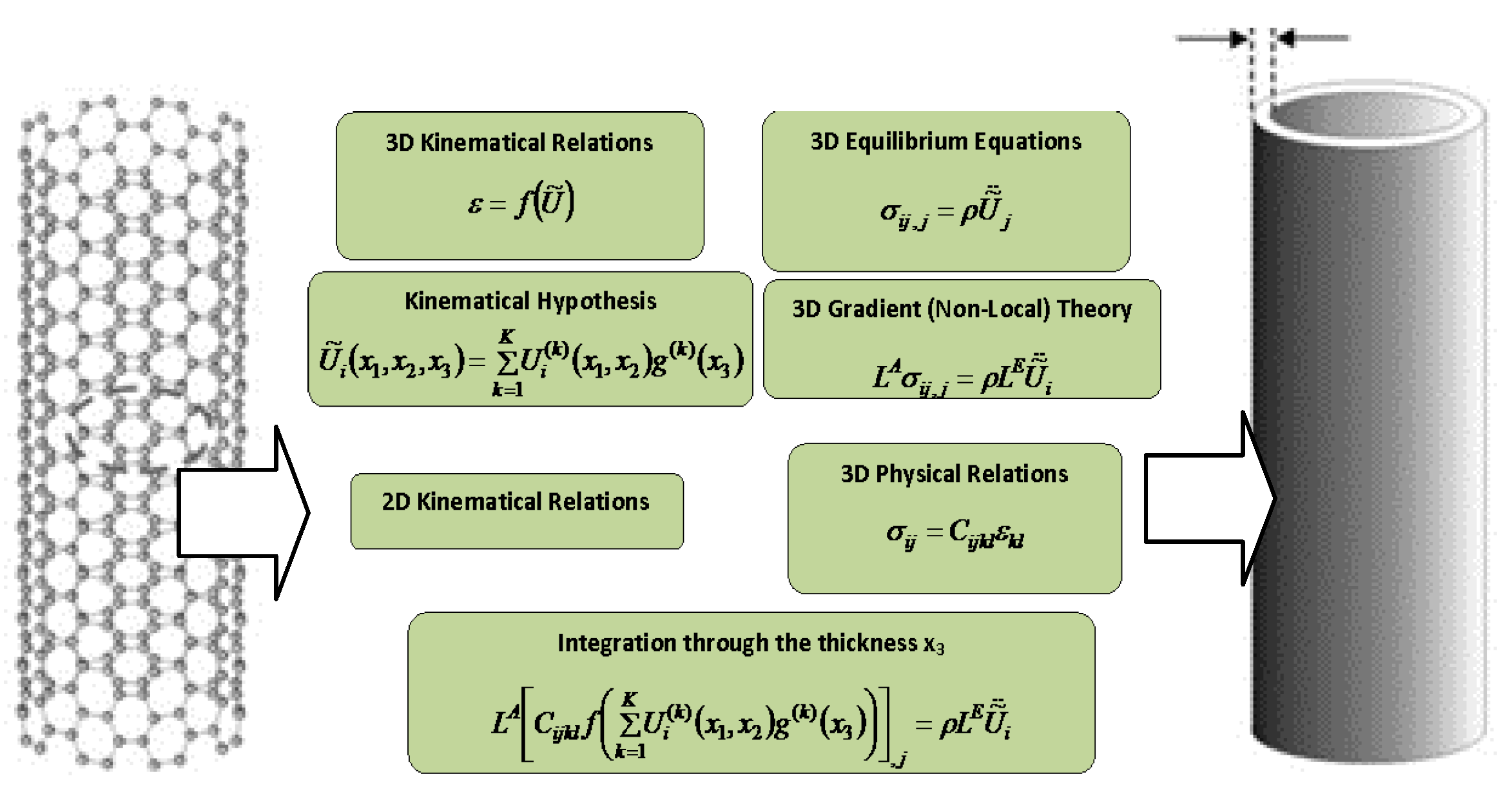
Figure 2.
Feedback vibration suppression control scheme using piezoelectric elements.
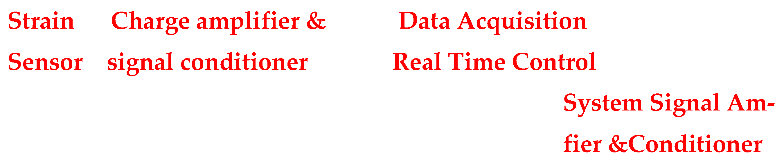
Figure 4.
Damping of radial displacements (NISAII).
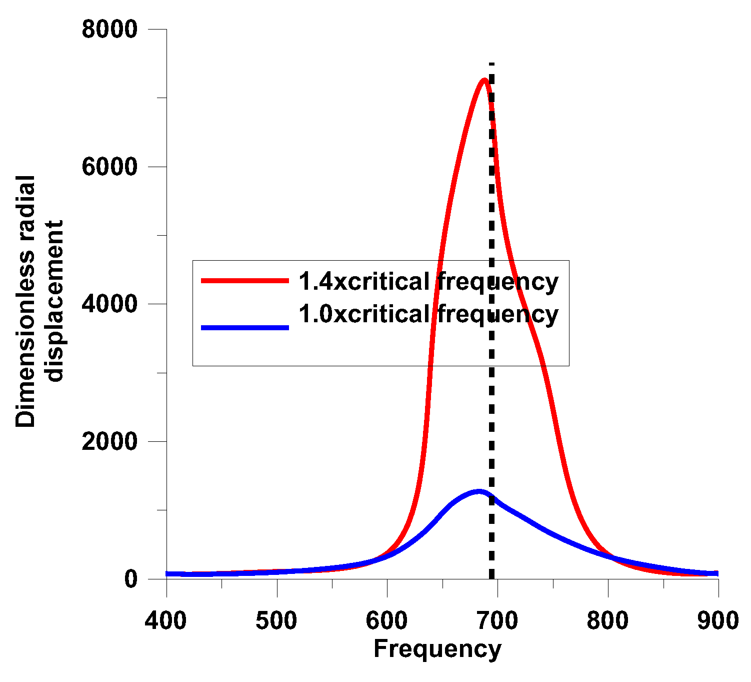
Figure 5.
The smart beam structure.
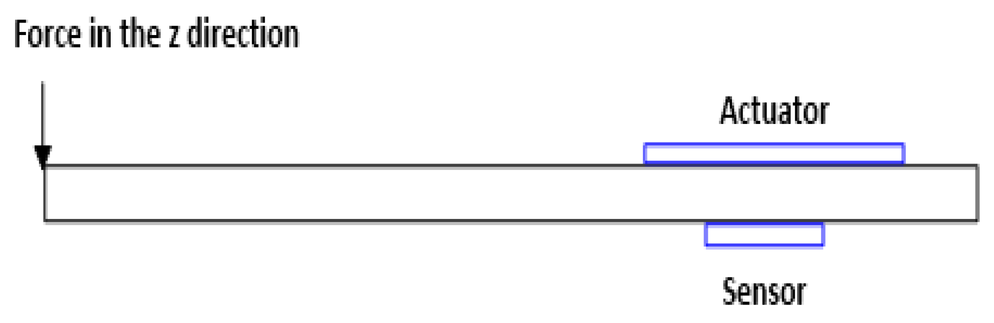
Figure 6.
a. The form of passive actuator (green colour). b. Resultant displacements of compressed panels – R/h=100, V=100 [V]. c. The form of passive actuator (green colour). d. Resultant displacements of compressed panels – R/h=100, V=100 [V].
Figure 6.
a. The form of passive actuator (green colour). b. Resultant displacements of compressed panels – R/h=100, V=100 [V]. c. The form of passive actuator (green colour). d. Resultant displacements of compressed panels – R/h=100, V=100 [V].
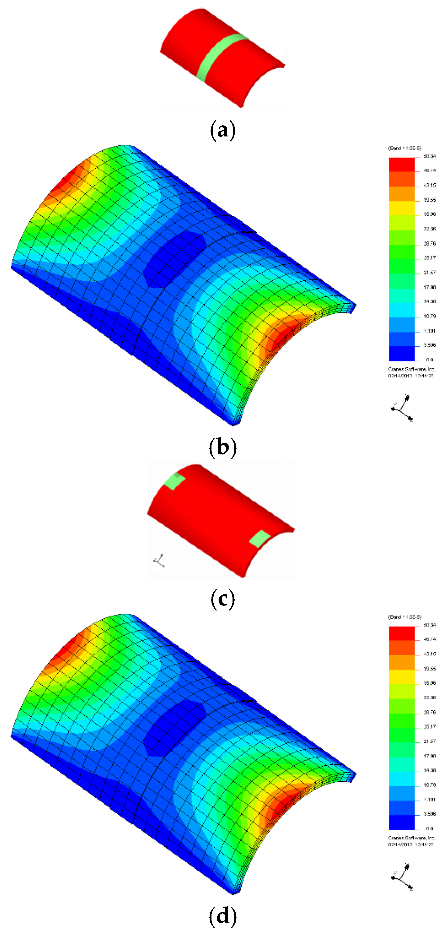
Figure 7.
The comparison between classical and nonlocal theories.
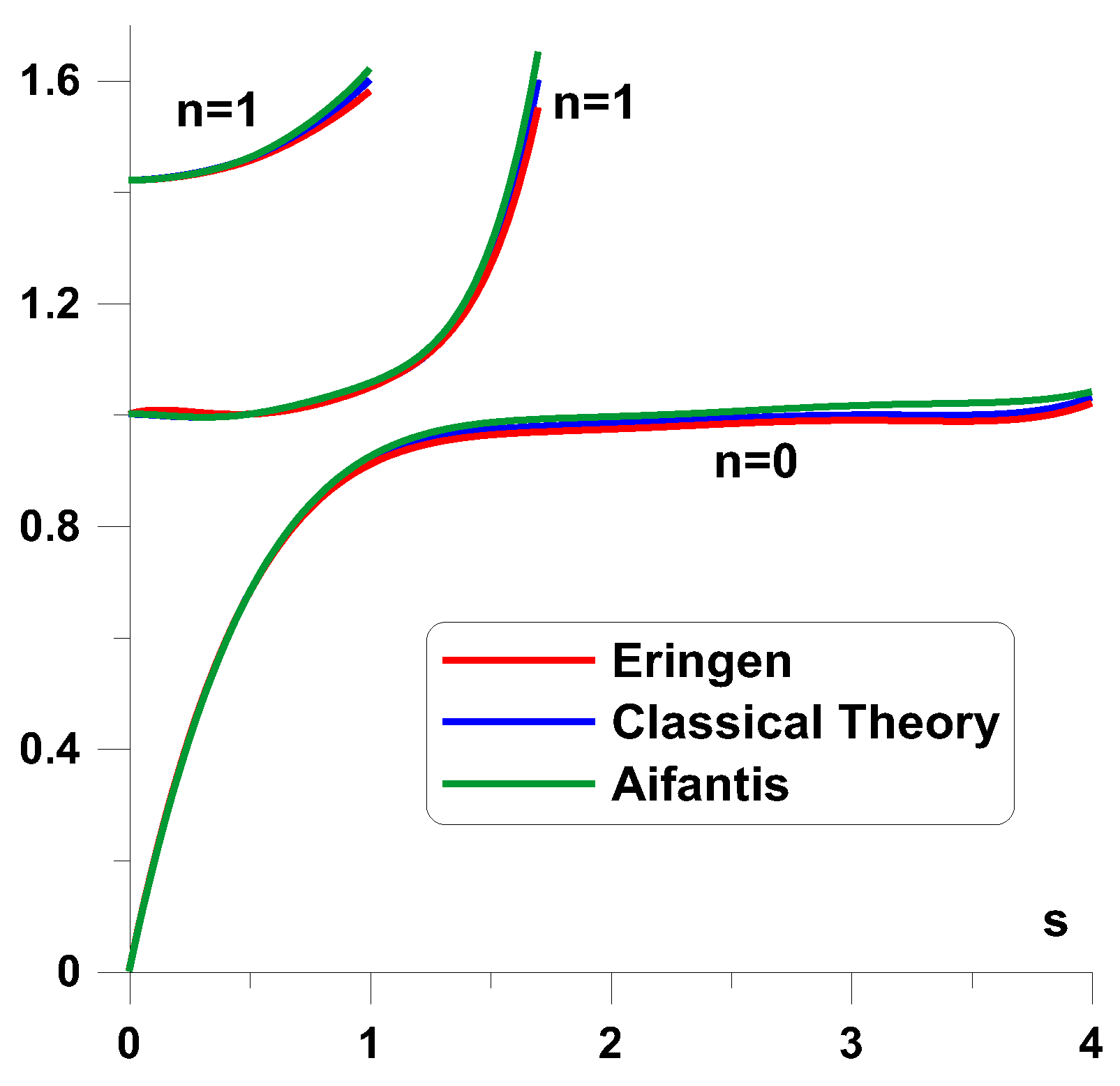

Table 1.
Cross-sections of structures with different actuators.
 |
 |
| (a) extension actuator | (b) shear actuator |
Table 2.
Variants of shell theories (TSE – transverse shear effects, SN – stretching of the normal, L-K Love Kirchhoff).
Table 2.
Variants of shell theories (TSE – transverse shear effects, SN – stretching of the normal, L-K Love Kirchhoff).
| Number of variables | Number of indepen-dent variables | ||
| TSE/ SN – [47,48] | 14 - u, v, w, ϕ1, ϕ2,, ψ1, ψ2, γ1, γ2, θ1, θ2,χ1, χ2 ,χ3 | 8 -u, v, w, ϕ1, ϕ2, χ1, χ2 ,χ3 | 4-th order TSE/ SN |
| TSE/ SN –– [49] | 13 - u, v, w, ϕ1, ϕ2,, ψ1, ψ2, γ1, γ2, θ1, θ2,χ1, χ2 | 7 -u, v, w, ϕ1, ϕ2, χ1, χ2 | 3-rd order TSE/ SN |
| TSE/ SN – [50], | 12 - u, v, w, ϕ1, ϕ2, , ψ1, ψ2, γ1, γ2, θ1, θ2,χ1 | 6 -u, v, w, ϕ1, ϕ2, χ1 | 3-rd order TSE/ SN |
| TSE [51] | 5 - u, v, w, ϕ1, ϕ2 | 5 - u, v, w, ϕ1, ϕ2 | 3-rd order TSE |
| TSE | 5 - u, v, w, ϕ1, ϕ2 | 5 - u, v, w, ϕ1, ϕ2 | 1-rd order TSE |
| L-K | 3 - u, v, w | 3 - u, v, w | L-K |
Table 3.
Comparison of the natural frequencies (R/h=5).
| Mode | Natural frequency [Hz] | ||
| [51] – FE 3D Model- ABAQUS |
Present analysis – NISA II |
||
| 1.Bending | 683.3 | 690.7 | 689.7 |
| 2. Out of plane | 2393.7 | 2454.1 | 2505.2 |
| 3. Bending | 2858.2 | 2907.4 | 2791.9 |
| 4. Out of plane | 4780.8 | 4783.4 | 4693.2 |
| 5. Bending | 5254.7 | 5292.1 | 5387.2 |
| 6. Out of plane | 7156.8 | 7342.6 | 7245.3 |
| 7.Bending | 7636.6 | 7600.4 | 7795.6 |
| 8. Bending | 9984.2 | 9645.2 | 9342.3 |
| 9. Shear | 10223.9 | 10443.9 | 10396.1 |
Table 4.
Comparison of the natural frequencies.
| Mode | Natural Frequency dB | ||
| Ansys Karagulle FE 3D Model | Present analysis – NISA II |
||
| FE – 2D | FE- 3D | ||
| 29.7 | 24.5 | 24.4 | |
Disclaimer/Publisher’s Note: The statements, opinions and data contained in all publications are solely those of the individual author(s) and contributor(s) and not of MDPI and/or the editor(s). MDPI and/or the editor(s) disclaim responsibility for any injury to people or property resulting from any ideas, methods, instructions or products referred to in the content. |
© 2025 by the author. Licensee MDPI, Basel, Switzerland. This article is an open access article distributed under the terms and conditions of the Creative Commons Attribution (CC BY) license (https://creativecommons.org/licenses/by/4.0/).
Copyright: This open access article is published under a Creative Commons CC BY 4.0 license, which permit the free download, distribution, and reuse, provided that the author and preprint are cited in any reuse.


