

Submitted:
14 July 2024
Posted:
15 July 2024
You are already at the latest version
Abstract
The increasing prevalence of spinal disorders and the subsequent rise in spinal fusion surgeries stress the necessity for optimizing spinal fusion cages, crucial for stabilizing the spine and supporting osseointegration. Despite the widespread attempts at material modifications and surface enhancements to improve these devices, failure rates and complications remain significant. This research explores an imaginitive approach to enhancing spinal fusion cages through the application of geometric tiling designs, a method scarcely employed . The study systematically investigates the potential of triangular, diamond, and hexagonal tiling patterns to improve the structural integrity and capability for osseointegration of spinal fusion cages. Through a finite element analysis simulation, each design's ability to withstand multi-directional loads and effectively distribute stress was tested under simulated conditions that mimic the complexities of spinal motion. Preliminary findings in fields of engineering indicate that geometric tiling can significantly enhance the load-bearing capabilities and stress distribution of spinal fusion cages, potentially reducing the likelihood of implant subsidence and failure. The triangular and hexagonal designs, in particular, demonstrate superior performance in maintaining structural stability under axial and anterior compressive forces compared to traditional cage designs. This research opens a new pathway for the development of more durable and efficient spinal fusion cages. By leveraging the structural advantages of geometric tiling, future spinal implants could achieve better clinical outcomes, leading to improved patient recovery and reduced rates of complications.
Keywords:
spinal fusion cages
; osseointegration
; geometric tiling
; stress distribution
; orthopedic implants
Introduction
Injuries, fractures, and other major back pain-inducing conditions, such as scoliosis, kyphosis, degenerative disc disease, and dislocation of the spine, have become increasingly prevalent in modern society. As a result, the main, exclusive treatment for these conditions, spinal implant surgeries (the implementation of devices that typically reduce deformity, provide stabilization, share loading with adjacent tissues, and support the fusion process) have been on the rise in the past few years [1]. Based upon data collected utilizing the CPT and ICD codes of doctors in the United States (codes that identify services rendered and patient diagnoses), it was estimated that there are over 1.5 million spinal procedures to be performed by the end of 2023 [2,3]. Despite all these spinal surgery cases impacting not only the people living in the United States but rather worldwide and all the opportunities for research and optimization, the failure rate of spinal implant devices, like spinal fusion cages (hollow intervertebral spacers used to stabilize the spine until fusion occurs [4]), is still devastatingly high. Patients experience nearly a 5% rate of implant-related complications, a staggering number for surgery on such a vital part of the body for both structural support and the nervous system [5]. Despite this, most studies have only looked toward optimizing these spinal fusion cages through the alteration of the primary material utilized, coating material, and surface alterations. For instance, most forms of optimization techniques for these spinal fusion cages have consisted of either the addition of pores and the addition of surface texture or roughness to the device itself to harbor improved osseointegration (the fusion of the implant with the bone), or for the alteration of material utilized in the main frame of the spinal fusion cage itself [6,7,8,9]. Few studies have begun to briefly delve into the capabilities of optimization through the application of varying structures of spinal cages [10,11].
As the applications of more complex structures for spinal cages are relatively unstudied, there exists a significant potential for the capabilities of optimizing the spinal fusion cages through it. Following the rise of a simple mesh design in this field [10], investigating the applications of more complex geometric tiling would provide further insight into the capabilities of spinal fusion cages. Exploring spinal fusion cages utilizing these new geometric designs could possibly lead to the development of more structurally efficient devices, also capable of successful osseointegration.
Literature Review
- Porous Structures in Spinal Fusion Cages
Arising from the severity of current spinal implant complications, many researchers have looked towards amending the spinal fusion cage design. One of the primary methods for optimizing the osseointegration of spinal cages is the incorporation of pores or the alteration of the surface of the device, an example of which is shown in Figure 1 below [6,7,8,17]. This optimization method allows for cell tissue to grow into the fusion cage, helping the device stabilize more effectively in the bone.
Gittens and his peers [6], all with backgrounds in biomedical engineering, helped to demonstrate this effect of improved osseointegration in their study on the effects of surface roughness of spinal implants in general. The researchers implemented an in-depth content analysis of the results of other experiments to analyze the effects of a rough surface for a spinal fusion implant. Through this, they concluded that the rougher surface allowed for more efficient osseointegration of the bone and implant. The results of this study coincided with that of Bandyopadhyay and his peers [8]. Here, the ability of various porous materials, composing the main body of a spinal fusion cage, were comprehensively studied, ultimately uncovering the capabilities of a porous metal compound to improve bone osseointegration. These findings were further supported by Tsou and his peers [7] in their research on the addition of a coating to the surface of the spinal fusion cage. The material used for this coating was titanium oxide, or TiO2, which is a highly porous material. Due to this quality, the incorporation of TiO2 in spinal fusion implants allowed for improved success of osseointegration. Multiple studies have demonstrated the capabilities of porous and textured materials on the enhancement of the property of osseointegration, due to increased contact area between bone and implant. It has also been shown to reduce the possibility of cage subsidence, or caving in, due to improved stress distribution.
- Alteration of Material Type in Spinal Fusion Cages
Another method commonly used to enhance the stability and quality of a spinal fusion cage is the alteration of the primary compound comprising the device. In both the study conducted by Rao and his peers [9] and Sun and his colleagues [18], a comparison of various materials was performed to construct a spinal fusion cage. Both studies agreed on the need for porous materials in the construction of spinal cages due to improved osseointegration. However, Sun concluded that a magnesium alloy was optimal since it reduced the stress shielding effect, where the fusion cage alleviates excessive pressure from the spine causing the development of a more fragile bone. On the other hand, Rao opted for a titanium alloy coating which allowed for high bioactivity, resistance to corrosion, and biocompatibility. Despite the differences in the conclusions of the two studies, it was agreed upon that the most optimal body material for spinal fusion cages involves the incorporation of a porous material that effectively balances the stress shielding effect to reduce possibilities for cage subsidence. Furthermore, Massaad and his colleagues [19] explored the two most common materials used in the creation of spinal fusion cages, titanium and polyether ether ketone (PEEK),. The paper provided an in-depth analysis of the benefits of each, resulting in the discovery that titanium resulted in higher successful fusion rates than PEEK. Despite these conflicting results, the importance of optimizing both the reduction of stress shielding through enhanced stress distribution and the improvement of fusion success. However, the current research that has been described fails to delve into the alteration of the base design of the spinal fusion cages to achieve these refinements.
- Basic Alteration of Structures for Spinal Fusion Cages
A scarcely studied method used to optimize spinal fusion cages is through the alteration of the design itself. In the article written by Postigo and his peers [20], with backgrounds in both mechanical engineering and musculoskeletal surgery, a finite element analysis was conducted to determine the feasibility of different structures of spinal cages. Of the structures that were tested, it was determined that a softer ring cage allowed for the most optimal stress shielding and osseointegration. Further alterations in cage design were studied by Shih and his peers [11] in their study of implementing side holes for better filling of bone grafts. The side holes demonstrated improved osseointegration at most fusion cage heights due to the improved ability to fill the device with bone graft. A more complex design alternative was proposed by authors Przekora and peers [10], with backgrounds in tissue engineering and regenerative medicine. Experimentation was implemented to determine the capabilities of the various cages for static compression and osseointegration. It demonstrated that the simple mesh design allowed for improved mechanical properties, such as improved compressive strength and reduced rates of cage subsidence, while maintaining its capabilities in osseointegration. However, there is currently a lack of supporting research on the complex alteration of base spinal fusion cage design. The renewed existence of concerns surrounding extreme loading fusion cage collapse, cage subsidence, and fusion failure, has failed to be properly optimized by current methods existing in this field of research, leading the way for possibilities in complex fusion cage design changes.
- Current Applications of Geometric Tiling
Geometric tiling, or tessellation, is the covering of a surface through the utilization of one or more geometric shapes with no overlaps or gaps. It currently has a wide range of applications in the modern world ranging from architectural designs to bio-mechanical structures and has been shown to provide greater load-bearing efficiency as well as better stress distribution [12,13,14,15,16].
The implementation of geometric tiling allows for the capability to create fascinating artwork while maintaining structural integrity for larger loads. In his research study, Robert Fathauer [12] explores many real-world examples of geometric tiling within both nature and modern society. Here he analyzes the tessellations of animals and artworks through images collected while traveling the world. The most notable of which were architectural artworks that incorporated geometric tessellations to create aesthetically pleasing images while still having a high load capacity. This concept of the architectural applications of geometric tilings was further expanded upon by Qiang Du and Desheng Wang [13], in their research study on new formations of geometric tessellations. Through their research on a new form of tessellation, the anisotropic centroidal Voronoi tessellation, they were able to determine, through the use of calculus-based mathematical physics equations, the structural integrity of these newly developed structures. The resulting statistical data demonstrated that the tessellations contained well-distributed vertices on their surface leading to the creation of a high quality, high load capacity material, also known as mesh. These structural improvements were also observed in the incorporation of simpler geometric tessellation designs on a larger scale through architecture. Takva and Ilerisoy [14], studied the performance of various geometric designs on the capabilities of a steel bridge. Utilizing finite element analysis software (computer simulation for predicting the behavior of models), the researchers conducted both static performance and cost analysis tests on the various structures. Their research uncovered significant information that triangular structures were efficient in planar models while triangular and hexagonal configurations were effective in curved models. Despite the distinction between designs, the primary conclusion of their findings still suggested that the utilization of geometric tiling greatly contributed to the structural integrity and load capacity of the bridge. In another study, researchers also looked towards geometric tiling in the provision of structural support to unique building designs [16]. The main designs analyzed included diamond, hexagonal, and triangular tiling designs. It provided that all three tiling designs were capable of evenly distributing pressure, therefore, making them suitable for applying to other models in need of optimizing structural integrity. This property of structural integrity of geometric tiling, as shown in both small and large-scale architectural investigations, can then be applied to spinal fusion cages in order to improve both its strength and durability.
- Summary of Literature
Current methods surrounding possibilities to optimize spinal fusion cages in both static compression and osseointegration have revolved around the alteration of the surface structure of the spinal fusion cage or the composition of the fusion cage itself. Recent studies have begun to delve into the possibilities of various structures of these fusion cages, such as the utilization of a simple mesh design. Its success prompts the investigation of more complex geometric tiling structures in spinal fusion cages for the direct enhancement of mechanical strength and osseointegration rates for improved clinical outcomes. This gap lends itself to the study of the following question: how can the implementation of a geometric tiling design be strategically incorporated into the design of spinal fusion cages to enhance its load-bearing efficiency and promote optimal osseointegration for improved clinical outcomes? As shown with previous successes in improving structural stability and durability within architecture, it was hypothesized that the implementation of geometric tiling could unlock the full capabilities of a spinal fusion cage’s stability, stress distribution, and osseointegration.
Methodology
Overview/Justification
In order to properly determine the efficacy of the application of a geometric tiling mesh design to spinal fusion cages, both durability, through its capability to handle extreme loads and properly balance the stress shielding effect with effective stress distribution, and capability for osseointegration must be tested. The spinal fusion cage’s durability should be tested under a multitude of conditions, specifically under direct vertical compression, extension, flexion, and lateral extension relative to the device’s placement in the spine. This will help to account for the multifaceted motion of the spine, which as detailed by Swartz, Floyd, and Cendoma, “is complex because pure uniplanar movement does not accurately portray the motion between cervical levels” [21]. The most common methods for testing spinal fusion cages have been completed through the use of online simulation software or direct experimentation with models [8,10,14,20,22,23]. However, due to the major fluctuation of outcomes which can result from minor imperfections in a concrete design, in combination with financial and technological constraints, a virtual simulation was selected to evaluate the spinal fusion cage designs. This allows for a simplified evaluation of structural durability, removing the possibilities of environmental and modeling imperfections. The independent variable tested was the shape of the geometric tiling mesh design of the spinal fusion cage while the dependent variable was the structural stability and durability of the fusion cage. This was tested through finite element analysis software, a computer program that performs mathematical calculations and simulations to analyze the performance of models under specified physical conditions. Due to a need for simplification of the load placement upon the virtual model of the spinal fusion cage, a static analysis was chosen to test the device at common angles of pressure - axial and anterior compression, which model vertical compression and forward bending. Data feedback through the static analysis was achieved by dividing the submitted model into many separate elements and then establishing the characteristics of the entire system by assembling the properties of the various elements [24]. This theoretical analysis process makes it possible to accurately determine the mechanical properties in specified directional load-bearing; therefore, making it an optimal and valid method for assessing the stability and durability of spinal fusion cages.
The geometric tiling designs to be approached in this study include a triangular tiling design, a diamond tiling design, and a hexagonal tiling design. These were selected due to their prevalence in architecture and load-bearing artworks; they have been evidenced in a multitude of construction works such as pyramids and bridges to provide structural stability [12,14,16]. Other designs that were considered included circular tiling designs, in which circles were laid in tangent to each other [25]. However, this design was ruled out due to the existence of gaps between each of the shapes, invalidating it under the definition of mathematical tiling. In addition, designs such as dodecahedrons and irregular shapes were considered; however, they were not utilized due to their complexity in modeling and maintaining an equal area with the other tiling patterns to be used in this study.
- Part I: Tiling Sketches
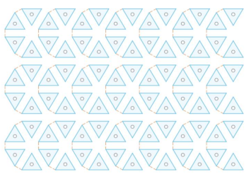
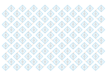
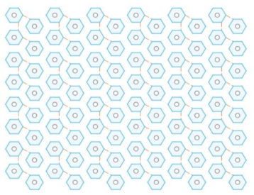
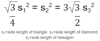
To begin modeling the incorporation of the tiling designs into the spinal fusion cage designs, two-dimensional designs of the tiling patterns were first created. This was completed within Fusion 360, a software for three-dimensional modeling. The triangular geometric tiling pattern was designed in the 2D sketch mode of Fusion 360 by first creating an equilateral triangle with a side length of 1.25 mm. A second equilateral triangle of the same dimensions was then placed facing the opposite direction with the adjacent sides 0.5 mm apart to allow for material to fill the areas when later applied to the base fusion cage geometry. This was then copied using a patterning tool to create a large plane of a triangular tiling design. In order to create the tiling sketches for both the diamond and hexagonal tiling designs, the same process was repeated; however, to determine the side lengths of each of the shapes to be used, the following equation was applied:
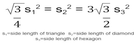
This equation was derived by setting the areas of the three shapes - an equilateral triangle, a square diamond, and a regular hexagon - equal to one another in order to maintain comparability of results when set under load-bearing conditions. It would ensure that a similar amount of material would be removed from the base fusion cage geometry, resulting in variations in load-bearing capabilities as a direct effect of the efficacies of the different tiling designs. Following this equation, each diamond was created with a side length of 0.823 mm, and each regular hexagon was created with a side length of .510 mm. The same gap of 0.5 mm between each shape was utilized throughout all three sketches to create the resulting tiling sketches, further ensuring variation in results directly stemmed from the changes in design. See Appendix A Table 1 for images of the modeled tiling designs and Appendix A Table 2 for listed dimensions for each tiling sketch.
- Part II: 3D Fusion Cage Modeling
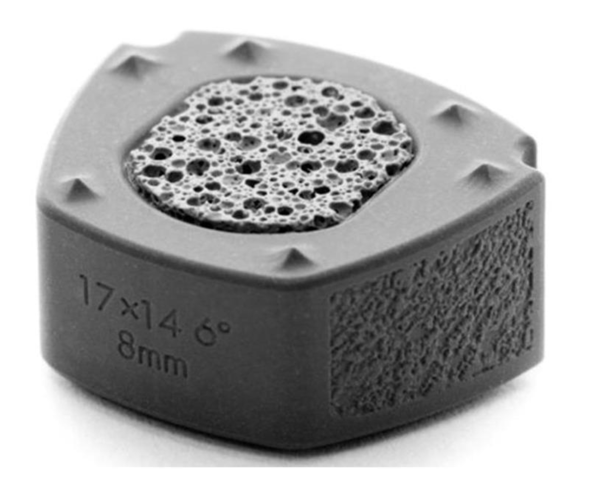
To render the designs for the spinal fusion cages, a base geometry for the tiling sketches to be applied was created. This was done by modeling the 3D figure based on spinal fusion cages outlined in prior studies to determine an accurate shape and dimension for the design [26,27,28]. The base geometry was modeled utilizing the two-dimensional sketch tool within Fusion 360 to create a trapezoid with rounded corners, using the line and filet tools, and then extruding the object to make it three-dimensional. This object was then made hollow using the shell tool with a wall thickness of 0.5 mm since spinal fusion cages are empty to allow for the bone graft to fill it. To provide the capability for comparison to current spinal fusion cage designs, a model was created based on that in Jain and his colleagues’ research study [28]. This design can be seen in the following, Figure 2, and was modeled in Fusion 360 by using the cut and hole tools on the base design which was previously fabricated.
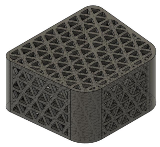
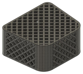
For the experimental designs of the spinal fusion cage, the previously constructed geometric tiling designs were then applied to all faces of the fusion cage, by extruding the sketches into each face of the formerly created body, to create a realistic model of a spinal fusion cage. This was done to create three separate models, one with the triangular tiling design, one with the diamond tiling design, and the other with the hexagonal tiling design. See Appendix A Table 1 for detailed images of each of the spinal fusion cages that were modeled and Appendix A Table 2 for the dimensions of each of the resulting spinal fusion cage designs.
- Part III: Finite Element Analysis Tests
These computer-rendered spinal fusion cages were then exported to the online Finite Element Analysis software, SimScale, selected for its user-friendliness, cost-effectiveness, and compatibility with Fusion 360, to be tested. Once the three designs were exported, SimScale automatically resized each of the fusion cages with a scale factor of 1000 so that each of the dimensions changed from millimeters to meters. This was a result of the computer’s inability to handle calculations on such a small scale in the thousandths of millimeters. To account for this, the resulting geometries were tested with a specified displacement of the spine rather than modeling the simulation with the average pressure exerted by the spine, since the resulting pressure would be scaled up to an incomprehensible amount, for it to be accurately represented. The following simulation stemmed from a combination of the parameters used for other researchers’ finite element analysis designs testing the compressive loading of spinal fusion cages and other supportive devices [29,30,31,32]. Each of the models was placed under a static linear test due to limits on the computing capabilities of the free simulation. To begin, a second-order mesh was generated with its boundaries set with sizing as automatic and fineness as moderate. The material selected for the designs was titanium, due to its frequent use in spinal fusion cages today [19]. Two compressional tests were conducted to model both axial and anterior compression in the spine. This was achieved by creating two compressional plates; the top plate was bonded to the top face of each spinal fusion cage, and the bottom plate was bonded to the bottom face of each spinal fusion cage. For both types of compressional tests, the bottom plate was set as a fixed support to prevent movement of the bottom face of the spinal fusion cage. To simulate axial compression, the top plate was set as a fixed value with a displacement set as -4*t m in the vertical direction. For the anterior compressional tests, the front face of the top plate was set with a displacement of -4*t m, and the back face of the top plate was set with a displacement of 2*t m to simulate forward bending. Both of these tests were conducted over a time interval of 1 second which was broken up into 0.1 second time intervals. For data collection, the average displacement and average von Mises stress of the entire volume of each spinal fusion cage were calculated by computer software and plotted in separate graphs with an x-axis of time. Solution fields following each simulation run were also provided which allowed for a visual display of the distribution of both stress and displacement, through variations in coloring, across each figure.
Following the completion of the compressional tests, the data was exported into Google Sheets to create data plots and charts. The data was utilized in order to plot a stress-strain curve, with the y-axis being the average von Mises stress, converted to units of MegaPascals (MPa), a form of pressure and tension measurement, and the x-axis being the stress, calculated from taking the average displacement in meters and dividing that by the original length in the direction of the displacement which was 8 m.
- Part IV: Osseointegration Analysis
In order to properly analyze the osseointegration capabilities of the spinal fusion cages, a multitude of factors must be considered. It has been evidenced that an increase in the surface area of contact between the implant and bone results in increased osseointegration alongside other factors such as bioactivity [33,34]. For this research study, only the surface area of the contact faces was measured since the bioactivity is either patient-specific or material-dependent. Since both the contact faces, the top and bottom faces of each spinal fusion cage, had the same area, only the surface area of the top face of all four designs was measured, including the base spinal fusion cage to allow for comparison to current osseointegration capabilities. This was done using the inspect tool in Fusion 360 on the models that were formerly rendered, which provided data feedback on the total surface area of a selected surface.
Results
The simulation data at each of the ten time steps of 0.1 seconds was plotted into stress-strain curves for both axial compression and anterior compression tests. Results for all four types of spinal fusion cage designs were plotted on the same graph for ease of comparison. The triangular tiling design is in blue, the base design is in red, the hexagonal tiling design is in orange, and the diamond tiling design is in green. The resulting graphs were used to plot a trendline with a y-intercept of 0, with the equation of each listed within the key for each model in the format of y = mx. Slope values can be determined using the coefficient of x in each equation.
The values for the surface area were plotted within a bar graph for ease of comparison with the same color coding as the compressive test stress-strain curves. The data for the slopes of the compressive tests, in MPa, and the data for the surface areas for the top face of each fusion cage design, in mm2, are listed in a separate table for ease of access.
Chart 1.
Axial Compression Tests.
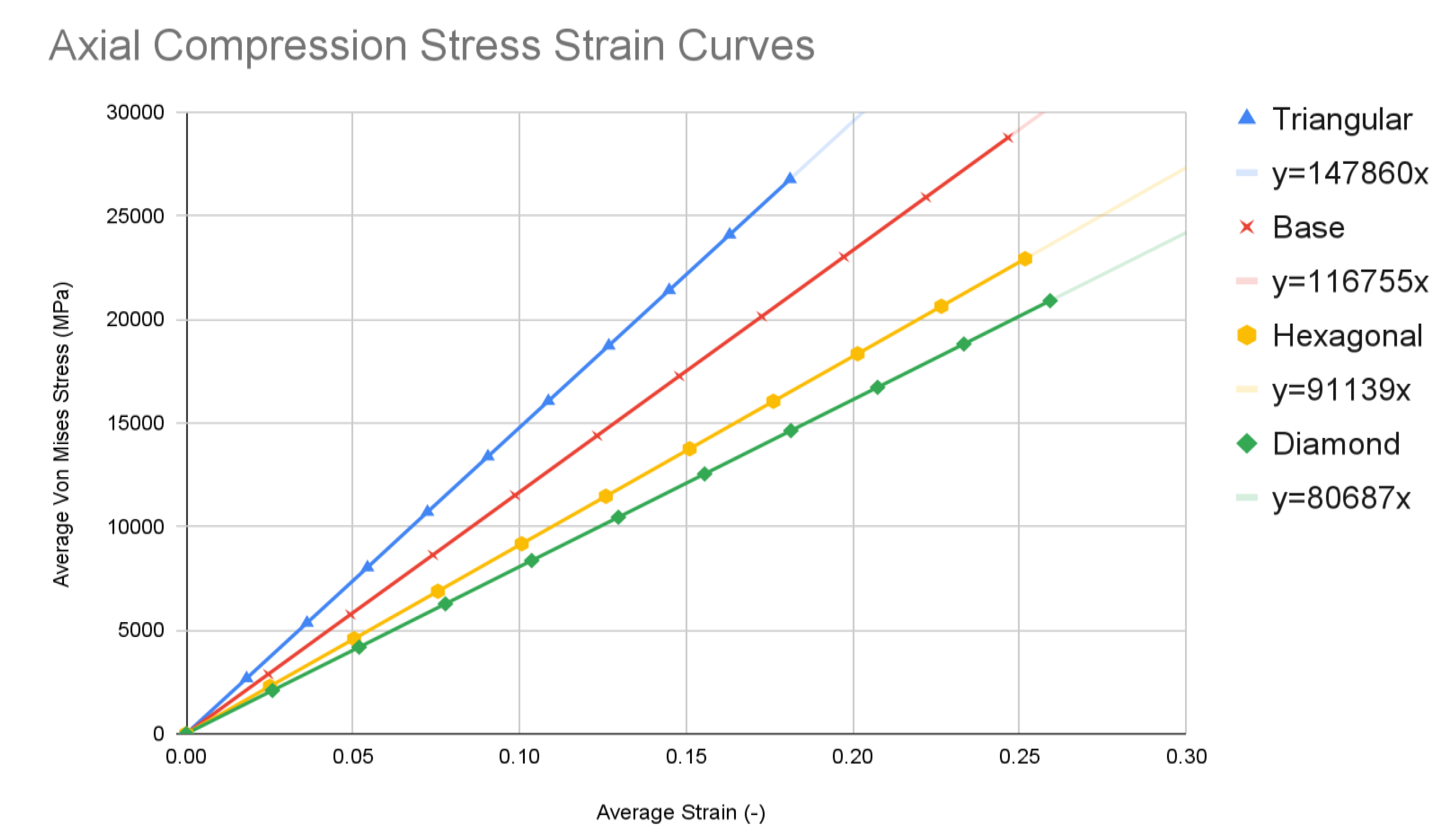
Chart 2.
Anterior Compression Tests.
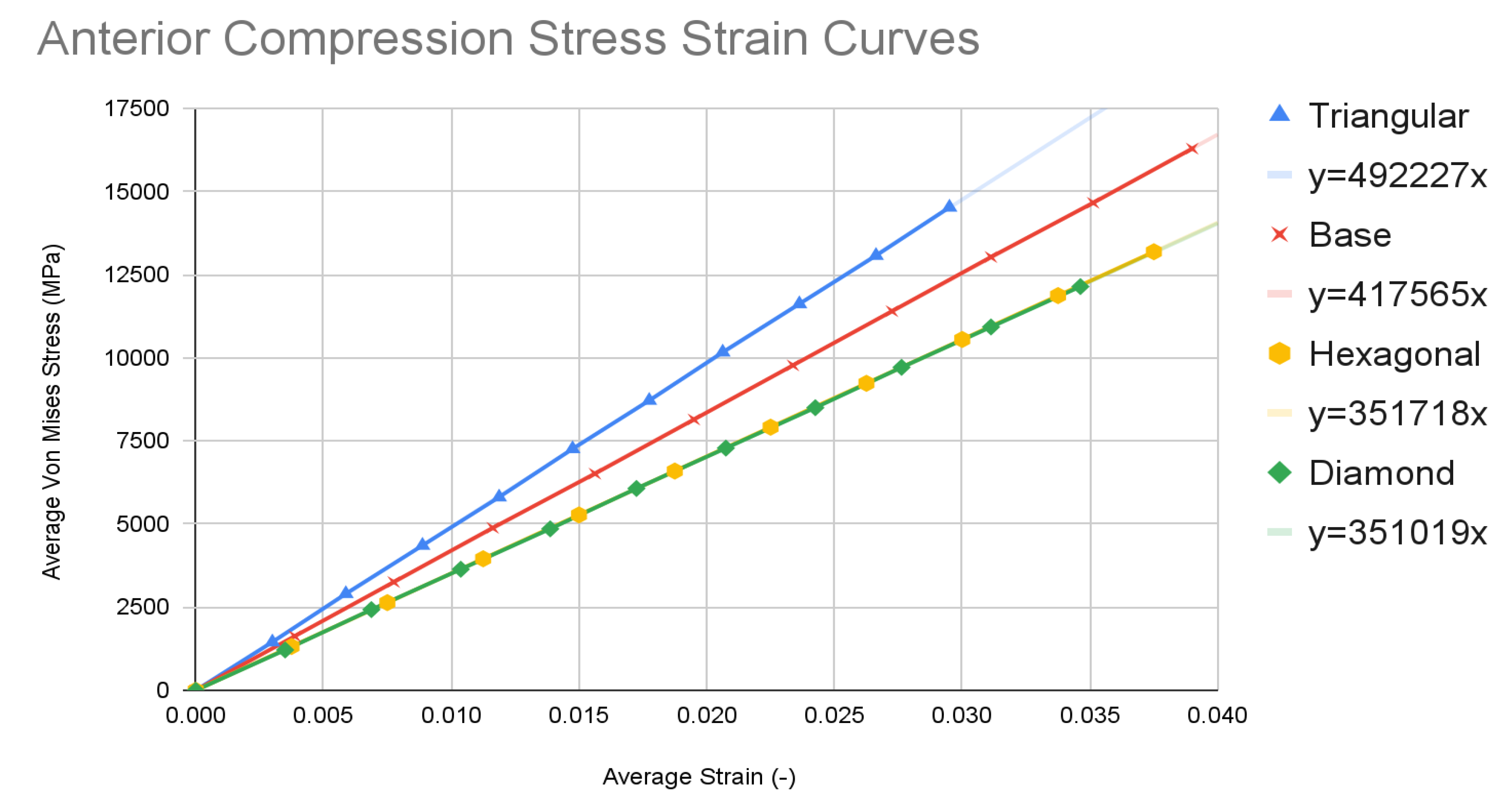
Chart 3.
Surface Area Calculations.
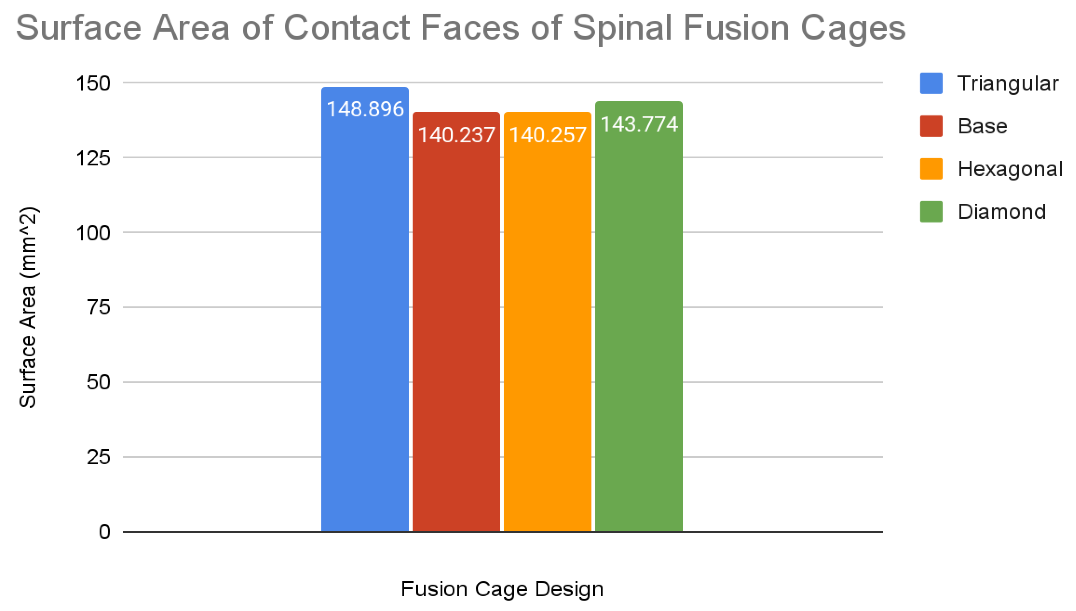

Table 1.
Slope and Surface Area Values.
| Test Type | Base | Triangular | Hexagonal | Diamond |
|---|---|---|---|---|
| Slope Values of Stress-Strain Curves (MPa) | ||||
| Axial Compression | 116755 | 147860 | 91139 | 80687 |
| Anterior Compression | 417565 | 492227 | 351718 | 351019 |
| Surface Area of Contact Faces of Spinal Fusion Cages (mm2) | ||||
| Surface Area | 140.237 | 148.896 | 140.257 | 143.774 |
Discussion
Base Spinal Fusion Cage Design
The base spinal fusion cage design was that which was based upon common designs for spinal fusion cages today, created to serve as a standard for comparison for the experimental tiling designs since each model was forced to scale up due to limited computing capabilities of the Finite Element Analysis software, SimScale. Under the axial compression tests, the base spinal fusion cage design had a maximum von Mises stress value, at time t = 1s, of 28785.4 MPa, and the maximum stress value was 0.2465, resulting in a trendline slope of 116755 MPa. Under anterior compressional tests, the base spinal fusion cage design had a maximum von Mises stress value of 16289.9 MPa, and a maximum stress value of 0.039, leading to a trendline slope of 417565 MPa for the stress-strain curve. For the evaluation of osseointegration, the surface area which was measured by the inspect tool of Fusion 360 of the top face of the base spinal fusion cage was 140.237 mm2. Despite the lack of structural supports integrated into its design, the modern-day fusion cage model achieved a ranking of second in handling compressional loads; however, it had the least amount of contact surface area, implying the worst capability for osseointegration.
- Triangular Tiling Spinal Fusion Cage Design
The triangular tiling design demonstrated strong improvements in both structural stability and osseointegration capabilities for the resulting fusion age design. Under axial compression conditions, the triangular tiling design was found to have a maximum von Mises stress value of 26776.1 MPa and a maximum strain value of 0.181125, resulting in a stress-strain slope value of 147860 MPa. In comparison to the base spinal fusion cage design, this was a demonstration of a drastic improvement of structural stability in vertical compression as indicated by the severely higher slope which suggests a capability for withstanding larger loads with minimal deformities. Due to the use of a stress-strain curve, a larger MPa slope value indicates a greater ratio between the load held and the original position of a node, therefore demonstrating better structural rigidity. When placed in anterior compressional tests, the triangular tiling spinal fusion cage design obtained a maximum von Mises stress value of 14526.5 MPa and a maximum strain value of 0.0295, leading to a slope of 492227 MPa. Again, the triangular tiling design proved to provide increased structural stability when compared to present-day spinal fusion cage designs. For its osseointegration tests, the triangular tiling design had the largest top contact face surface area of 148.898, revealing a better capability for fusion between bone and implant. When compared to the other fusion cage designs tested, the triangular tiling fusion cage achieved the greatest overall load-bearing strength, due to its unique capability to evenly distribute stress, and had the highest osseointegration success.
- Hexagonal Tiling Spinal Fusion Cage Design
The hexagonal tiling design resulted in diminished abilities to handle stress when compared to current developments in spinal fusion cages. Its maximum stress and strain were 22936 MPa and 0.251625 respectively under axial compression, generating a slope value of 91139 MPa. In anterior compression tests, the maximum von Mises stress and strain were 13189.4 MPa and 0.0375 respectively, producing a slope of 351718 MPa. Both of these values demonstrated an inability to handle stress prior to deformation in both direct vertical compression and forward bending when compared to both the base spinal fusion cage and triangular tiling design. However, the hexagonal spinal fusion cage design proved to have only a slightly better osseointegration rate than the base design with its contact surface area being 140.257 mm2. Therefore, the hexagonal tiling design is a suboptimal addition to spinal fusion cages due to its diminished ability to handle stress despite its minimal improvement to osseointegration success.
- Diamond Tiling Spinal Fusion Cage Design
The diamond tiling design performed the worst under both compressional load conditions, achieving a stress-strain slope value of 80687 MPa under axial compression and 351019 MPa under anterior compression, demonstrating a diminished capability of handling stress prior to deformation in both compressional directions. In spite of this, the diamond tiling design achieved greater success in terms of osseointegration efficiency with a surface area of 148.896 mm2. The diamond tiling design would theoretically be able to have a higher rate of osseointegration success than both the hexagonal and base spinal fusion cage designs due to this increased surface area.
- Solution Fields of Simulation Data
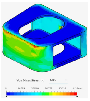
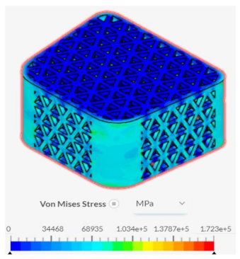
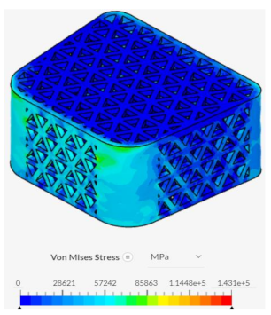
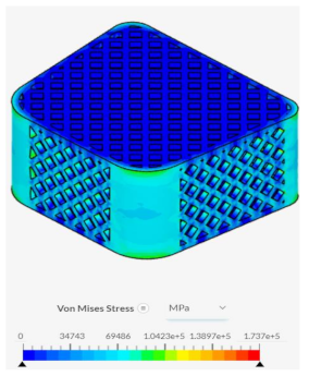
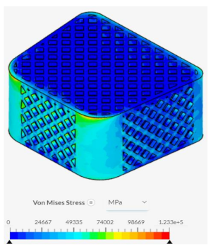
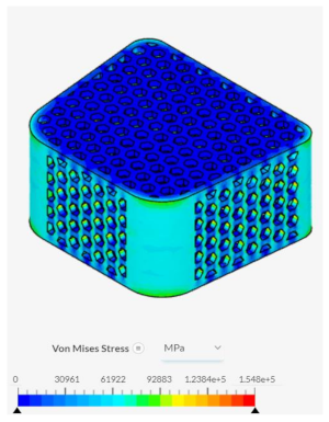
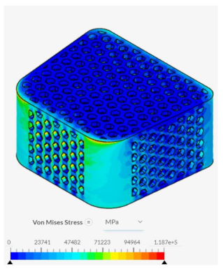
Despite failing to successfully perform under the load-bearing conditions of both axial and anterior compression, the hexagonal and diamond tiling spinal fusion cage designs did show indications of proper stress handling. When analyzing the solution fields generated in SimScale following the compressional tests, it can be noticed that both the designs were able to evenly distribute the stress loading as indicated by the overall bluer color. This trend was also indicated within the stress distribution of the triangular tiling fusion cage design. However, the base spinal fusion cage was unable to properly distribute the load around the entire body, creating regions of extreme pressure, as indicated by the yellower color on certain faces of the fusion cage. See Appendix C Table 1 for in-depth images regarding the solution fields. The even stress distribution witnessed throughout all three of the geometric tiling designs unveils the ability to reduce the possibilities of cage subsidence, which has been shown to diminish with either proper stress distribution within the cage itself or between the cage and bone for reduction of the stress shielding effect.
Conclusion
This study uncovered that the application of geometric tiling designs to spinal fusion cages had an overall positive effect on its capabilities for load-bearing and bone fusion success. It can be concluded that the application of a triangular tiling fusion cage will help to reduce the high-risk factor associated with spinal fusion surgeries today. Due to its performance in both the axial and anterior compression tests, the triangular tiling design has demonstrated enhanced durability and optimal stress distribution, lending itself to be more advantageous for extreme loading conditions as well as for the reduction of the stress shielding effect, and, in turn, cage subsidence. With its large surface area, the triangular tiling design also improves success rates of osseointegration within the spine when implemented. The implications of the widespread application of the triangular tiling design to spinal fusion cages would be a significant rise in the rate of success of spinal fusion surgery due to a reduction of failure rate, resulting from unsuccessful fusion and cage subsidence, of spinal fusion cages. People working in occupations requiring extreme amounts of pressure to be placed on their spine will have a reliable solution to degenerative spinal diseases that may plague them due to the capabilities of the triangular tiling spinal fusion cage to withstand more extreme loads, therefore, lessening rates of failure under excessive stress.
Limitations
This study’s limitations originate largely from the use of the free version of the simulation software system, SimScale. The simulation program that was selected only allowed for a limited amount of computational cores and hours which severely diminished the extent of complexity to which both the spinal fusion cage geometry and simulation could be. As a result of this, the model geometry’s dimensions were multiplied by a scale factor of 1000, to simplify complications, and the material selection forced the use of pure titanium rather than a more commonly used titanium alloy. In addition to this, due to the limited computational resources, a 3D rendition of the spine was not able to be modeled to run the compressional tests within, limiting the accuracy of the simulation of the spinal fusion cage’s direct interaction with the spine. Due to time constraints, the varying tiling designs were only applied to one type of spinal fusion cage, severely limiting the scope of the application of these benefits.
Future Directions
The concepts and results surrounding this study lend themselves to further experimentation in running similar tests within lab experimentation or purchasable simulation software in order to avoid the simplifications that occur within free versions of finite element analysis software. This could allow for the true interaction of the spinal fusion cage with the surface of the spine to be modeled, alongside the filling of each fusion cage with bone graft and accurately measuring the osseointegration success rate of each tiling design. To expand the reach of the results gained in this study, applications of these tiling designs to other spinal fusion cages as well as other orthopedic devices should be tested to see if a similar effect is held on its structural durability.
Final Thoughts
Ultimately, this study was able to complete its overall goal of testing geometric tiling designs as a viable method for the optimization of spinal fusion cages. Its findings validate the use of the triangular tiling design in spinal fusion cages for both enhanced durability and fusion to bone. Further design improvements through direct exposure of the spinal fusion cage to spinal environmental factors will hopefully lead to a reduction in implant complications. The knowledge that was gained on the mechanical properties of mathematical designs when applied to biomechanics can lead the way for research on other complex fusion cage design alterations, administering a more successful form of treatment to those affected by degenerative spine diseases.
Appendix A: Spinal Fusion Cage Design
Table 1 includes the designs for the main spinal fusion cages being tested in this research project. The left side of the table shows the tiling patterns, which were created in the sketch mode of the software Fusion 360, and were applied to the base geometry of a spinal fusion cage. The resulting figures following the application of the sketches onto the base geometry are depicted on the right side of the table which were created in Fusion 360’s 3D modeling software.
| Table 1: Tiling Design and Application to Spinal Fusion Cage | |
|---|---|
| Triangular Tiling | Triangular Tiling on Surface of Spinal Fusion Cage |
|
 |
| Diamond Tiling | Diamond Tiling on Surface of Spinal Fusion Cage |
|
 |
| Hexagonal Tiling | Hexagonal Tiling on Surface of Spinal Fusion Cage |
 |
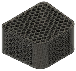 |
Table 2 includes the dimensions for the spinal fusion cage geometries that were tested in the simulation. The base dimensions were created based upon a study conducted by Jain et al [28]. The dimensions for each of the tiling dimension designs were based upon the following equation in which the fusion cage geometry for the triangular tiling design was divided into an adequate number, and the other geometric dimensions were then modeled to cover the same area in order to provide comparable results from the simulation tests.
| Table 2: Spinal Fusion Cage Design Dimensions | |||
|---|---|---|---|
| Base Spinal Fusion Cage Dimensions | Tiling Design Dimensions | ||
| Base 1 Length | 17.000 mm | Triangular Tiling Design | |
| Base 2 Length | 14.000 mm | Side Length | 1.250 mm |
| Base 1 Angles | 84.000 degrees | Spacing Distance | 0.500 mm |
| Base 2 Angles | 96.000 degrees | Diamond Tiling Design | |
| Base 1 Filet Length | 1.500 mm | Side Length | 0.823 mm |
| Base 2 Filet Length | 3.000 mm | Spacing Distance | 0.500 mm |
| Leg 1 Length | 14.350 mm | Hexagonal Tiling Design | |
| Leg 2 Length | 14.350 mm | Side Length | 0.510 mm |
| Height | 8.000 mm | Spacing Distance | 0.500 mm |
Appendix B: Finite Element Analysis Parameters
Table 1 includes the simulation parameters that were utilized in order to place each spinal fusion cage design under an axial compressive strength test. Each design was placed under separate simulation projects within SimScale; however, the parameters were maintained throughout each iteration in order to maintain the comparability of results.
| Table 1: Simulation Parameters (Axial Compression Testing)Static Linear Analysis | |
|---|---|
| Contacts | |
| Bonded 1 | |
| Position Tolerance | Off |
| Master Assignment | Bottom Face of Top Plate |
| Slave Assignment | Top Face of Fusion Cage |
| Bonded 2 | |
| Position Tolerance | Off |
| Master Assignment | Top Face of Bottom Plate |
| Slave Assignment | Bottom Face of Fusion Cage |
| Connectors | |
| None | |
| Element Technology | |
| Definition | Automatic |
| Model | |
| Gravity Magnitude | 0 m/s2 |
| Gravity Direction | 0m in x,y, and z directions |
| Materials | |
| Titanium | |
| Material Behavior | Linear Elastic |
| Direction Dependency | Isotropic |
| (E) Young’s Modulus | 1.05e+11 Pa |
| (v) Poisson’s Ratio | 0.34 |
| (p) Density | 4500 kg/m3 |
| Assigned Volumes | Top Plate, Bottom Plate, and Spinal Fusion Cage |
| Boundary Conditions | |
| Fixed Value | |
| Displacement | 0 m in x, 0 m in y, -4*t m in z |
| Assigned Faces | Bottom Face of Top Plate |
| Fixed Support | |
| Assigned Volumes | Bottom Plate |
| Numerics | |
| Solver | MUMPS |
| Precision Singularity Detection | 8 |
| Stop If Singular | True |
| Matrix Type | Automatic Detection |
| Memory for Pivoting (%) | 20 |
| Linear System Relative Residual | 1e-5 |
| Preprocessing | True |
| Renumbering Method | SCOTCH |
| Post Processing | Active |
| Distributed Matrix Storage | True |
| Memory Management | Automatic |
| Simulation Control | |
| Pseudo Time Stepping | Stepping List |
| Simulation Intervals | 1s |
| Time Step Length | 0.1s |
| Processors | |
| Number of Processors | Automatic (max 16) |
| Maximum Runtime | 3600s |
| Result Control | |
| Solution Fields | Displacement, Cauchy Stress, Von Mises Stress, Total Strain |
| Area Calculation | None |
| Volume Calculation | |
| Average 1 | |
| Volume Calculation | Average |
| Field Selection | Displacement |
| Component Selection | All |
| Assigned Volumes | Spinal Fusion Cage |
| Average 2 | |
| Volume Calculation | Average |
| Field Selection | Stress |
| Stress Type | Von Mises |
| Assigned Volumes | Spinal Fusion Cage |
| Point Data | None |
| Mesh | |
| Algorithm | Standard |
| Sizing | Automatic |
| Fineness | 5 |
| Number of Processors | Automatic (max 16) |
| Maximum Meshing Runtime | 1.8e+4 s |
| Small Feature Suppression | 1.41e-4 m |
| Gap Refinement Factor | 0 |
| Global Graduation Rate | 1.22 |
Table 2 includes the simulation parameters which were utilized in order to place each spinal fusion cage design under an anterior compressive strength test. Each design was placed under separate simulation projects within SimScale; however, the parameters were maintained throughout each iteration in order to maintain comparability of results.
| Table 2: Simulation Parameters (Anterior Compression Testing)Static Linear Analysis | |
|---|---|
| Contacts | |
| Bonded 1 | |
| Position Tolerance | Off |
| Master Assignment | Bottom Face of Top Plate |
| Slave Assignment | Top Face of Fusion Cage |
| Bonded 2 | |
| Position Tolerance | Off |
| Master Assignment | Top Face of Bottom Plate |
| Slave Assignment | Bottom Face of Fusion Cage |
| Connectors | |
| None | |
| Element Technology | |
| Definition | Automatic |
| Model | |
| Gravity Magnitude | 0 m/s2 |
| Gravity Direction | 0m in x,y, and z directions |
| Materials | |
| Titanium | |
| Material Behavior | Linear Elastic |
| Direction Dependency | Isotropic |
| (E) Young’s Modulus | 1.05e+11 Pa |
| (v) Poisson’s Ratio | 0.34 |
| (p) Density | 4500 kg/m3 |
| Assigned Volumes | Top Plate, Bottom Plate, and Spinal Fusion Cage |
| Boundary Conditions | |
| Fixed Value | |
| Displacement | 0 m in x, 0 m in y, -4*t m in z |
| Assigned Faces | Front Face of Top Plate |
| Fixed Value | |
| Displacement | 0 m in x, 0 m in y, 2*t m in z |
| Assigned Faces | Back Face of Top Plate |
| Fixed Support | |
| Assigned Volumes | Bottom Plate |
| Numerics | |
| Solver | MUMPS |
| Precision Singularity Detection | 8 |
| Stop If Singular | True |
| Matrix Type | Automatic Detection |
| Memory for Pivoting (%) | 20 |
| Linear System Relative Residual | 1e-5 |
| Preprocessing | True |
| Renumbering Method | SCOTCH |
| Post Processing | Active |
| Distributed Matrix Storage | True |
| Memory Management | Automatic |
| Simulation Control | |
| Pseudo Time Stepping | Stepping List |
| Simulation Intervals | 1s |
| Time Step Length | 0.1s |
| Processors | |
| Number of Processors | Automatic (max 16) |
| Maximum Runtime | 3600s |
| Result Control | |
| Solution Fields | Displacement, Cauchy Stress, Von Mises Stress, Total Strain |
| Area Calculation | None |
| Volume Calculation | |
| Average 1 | |
| Volume Calculation | Average |
| Field Selection | Displacement |
| Component Selection | All |
| Assigned Volumes | Spinal Fusion Cage |
| Average 2 | |
| Volume Calculation | Average |
| Field Selection | Stress |
| Stress Type | Von Mises |
| Assigned Volumes | Spinal Fusion Cage |
| Point Data | None |
| Mesh | |
| Algorithm | Standard |
| Sizing | Automatic |
| Fineness | 5 |
| Number of Processors | Automatic (max 16) |
| Maximum Meshing Runtime | 1.8e+4 s |
| Small Feature Suppression | 1.41e-4 m |
| Gap Refinement Factor | 0 |
| Global Graduation Rate | 1.22 |
Appendix C: Solution Fields
Table 1 includes the solution fields which were collected following each simulation run in SimScale. It displays the von Mises stress distribution in MPa across each model through variation in coloring. Blue or cooler coloring indicates a lower value of von Mises stress while a red or warmer color indicates a higher von Mises stress value. Displacement field values were disabled to make the resulting solution fields more comprehensible.
| Table 1: Solution Fields of Each Spinal Fusion Cage Design | |
|---|---|
| Base Design under Axial Compression | Base Design under Anterior Compression |
 |
 |
| Triangular Tiling Design under Axial Compression | Triangular Tiling Design under Axial Compression |
 |
 |
| Diamond Tiling Design under Axial Compression | Diamond Tiling Design under Axial Compression |
 |
 |
| Hexagonal Tiling Design under Axial Compression | Hexagonal Tiling Design under Axial Compression |
 |
 |
References
- J.S. Ross, B.R. Bendok, J. McClendon, “Devices and Instrumentation Overview.” Imaging in Spine Surgery (2017), pp. 62-63. [CrossRef]
- A.J. Duffy et al., “Commonly used CPT codes,” NATA, 01-May-2018. [Online]. Available: https://www.nata.org/practice-patient-care/revenue-reimbursement/general-revenue-reimbursement/commonly-used-cpt-codes#:~:text=While%20CPT%20codes%20are%20similar,10%20codes%20represent%20patient%20diagnoses. [Accessed: 13-Nov-2023].
- iData Research, “How many spinal fusions are performed each year in the United States?,” iData Research, 16-Aug-2023. [Online]. Available: https://idataresearch.com/how-many-instrumented-spinal-fusions-are-performed-each-year-in-the-united-states/. [Accessed: 21-Nov-2023].
- M. Laubach, P. Kobbe, D.W. Hutmacher, “Biodegradable interbody cages for lumbar spine fusion: Current concepts and future directions.” Biomaterials Vol 288 (2022). [CrossRef]
- H. Koshimizu et al., “Implant-Related Complications after Spinal Fusion: A Multicenter Study.” Global Spine Journal (2022). [CrossRef]
- R.A. Gittens et al., “Implant osseointegration and the role of microroughness and nanostructures: lessons for spine implants.” Acta Biomater (2014). [CrossRef]
- H. Tsou et al., "In Vivo Osseointegration Performance of Titanium Dioxide Coating Modified Polyetheretherketone Using Arc Ion Plating for Spinal Implant Application.” BioMed Research International (2015), pp 1-9. [CrossRef]
- A. Bandyopadhyay et al., “Porous metal implants: processing, properties, and challenges.” International Journal of Extreme Manufacturing Vol. 5 (2023). [CrossRef]
- P.J. Rao et al., “Spine Interbody Implants: Material Selection and Modification, Functionalization and Bioactivation of Surfaces to Improve Osseointegration.” Orthopedic Surgery Vol. 6 (2014), pp. 81-89. [CrossRef]
- A. Przekora et al., “Mesh Ti6Al4V Material Manufactured by Selective Laser Melting (SLM) as a Promising Intervertebral Fusion Cage.” International Journal of Molecular Sciences (2022). [CrossRef]
- C. Shih et al., “Optimizing Spinal Fusion Cage Design to Improve Bone Substitute Filling on Varying Disc Heights: A 3D Printing Study.” Bioengineering Vol. 10 (2023). [CrossRef]
- R.W. Fathauer, “Real-World Tessellations.” Proceedings of Bridges 2015: Mathematics, Music, Art, Architecture, Culture (2015), https://archive.bridgesmathart.org/2015/bridges2015-107.pdf.
- Q. Du and D. Wang, “Anisotropic Centroidal Voronoi Tessellations and Their Applications.” Siam Journal of Scientific Computation Vol. 26 (2005), pp. 737-761. [CrossRef]
- C. Takva and Z.Y. Ilerisoy, “Structural analysis of steel load-bearing systems using tessellation method in geometric architectural design.” Sadhana Academy Proceedings in Engineering Science Vol. 48 (2023), pp. 1-16. [CrossRef]
- C. Gao and Y. Li, “Mechanical model of bio-inspired composites with sutural tessellation.” Journal of the Mechanics and Physics of Solids Vol. 122 (2019), pp. 190-204. [CrossRef]
- C. Takva, F.G. Takva, Y. Takva, “Geometric Design in Architecture: Examination of Tessellation Configurations in Structural Systems.” Periodica Polytechnica Architecture Vol. 54 (2023), pp. 167-176, DOI: https://doi.org/10.3311/PPar.22824J. Xiao et al., “Design and Biomechanical Properties of Symmetrical Lumbar Fusion Cage Based on Lightweight Titanium Alloy Flexible Microporous Metal Rubber.” Symmetry Vol. 15 (2023). [CrossRef]
- J. Sun et al., “A lattice topology optimization of cervical interbody fusion cage and finite element comparison with ZK60 and Ti-6Al-4V cages.” BMC Musculoskeletal Disorders Vol. 22 (2021). [CrossRef]
- E. Massaad et al., “Polyetheretherketone Versus Titanium Cages for Posterior Lumbar Interbody Fusion: Meta-Analysis and Review of the Literature.” Neurospine Vol. 17 (2020), pp. 125-135. [CrossRef]
- S. Postigo et al., “Investigation of different cage designs and mechanoregulation algorithms in the lumbar interbody fusion process - A finite element analysis.” Journal of Biomechanics Vol. 47 (2014), pp. 1514-1519. [CrossRef]
- E.E. Swartz, R.T. Floyd, M. Cendoma, “Cervical Spine Functional Anatomy and the Biomechanics of Injury Due to Compressive Loading.” Journal of Athletic Training Vol. 40 (2005), pp. 155-161. [PubMed]
- X. Cao et al., “Compression experiment and numerical evaluation on mechanical responses of the lattice structures with stochastic geometric defects originated from additive-manufacturing.” Composites Part B: Engineering Vol. 194 (2020). [CrossRef]
- A. Welch-Phillips et al., “What is Finite Element Analysis?” Clinical Spine Surgery Vol. 33 (2020), pp. 323-324. [CrossRef]
- K.K. Pradhan, S. Chakraverty, “Chapter Four - Finite Element Method.” Computational Structural Mechanics (2019), pp. 25-28. [CrossRef]
- C. Zong, “Packing, covering and tiling in two-dimensional spaces.” Expositiones Mathematicae Vol. 32 (2014), pp. 297-364. [CrossRef]
- C. Sun et al., “Length of Lumbar Interbody Cage Using Radiological Measurements of Chinese Endplates and the Apophyseal Ring.” World Neurosurgery (2018), pp. 1204-1213. [CrossRef]
- H. Wang et al., “Analysis of the correlative factors in the selection of interbody fusion cage height in transforaminal lumbar interbody fusion.” BMC Musculoskeletal Disorders Vol. 17 (2016). [CrossRef]
- S. Jain et al., “Advances in Spinal Interbody Cages.” Orthopedic Surgery Vol. 8 (2016), pp. 278-284. [CrossRef]
- Z. Zhang et al., “Biomechanical Analysis of Porous Additive Manufactured Cages for Lateral Lumbar Interbody Fusion: A Finite Element Analysis.” World Neurosurgery Vol. 111 (2018), pp. 581-591.
- https://doi.org/10.1016/j.wneu.2017.12.127.
- F. Triawan et al., “Finite Element Analysis on the Unloading Elastic Modulus of Aluminum Foams by Unit-Cell Model.” IOP Conference Series Material Science and Engineering Vol. 288 (2018). [CrossRef]
- B. Sun et al., “Biomechanical analysis of customized cage conforming to the endplate morphology in anterior cervical discectomy fusion: A finite element analysis.” Heliyon Vol. 9 (2023). [CrossRef]
- E.J. Cheal et al., “Three-dimensional finite element analysis of a simplified compression plate fixation system.” Journal of Biomechanical Engineering Vol. 106 (1984) pp. 295-301. [CrossRef]
- A. Hudecki, G. Kiryczynski, M.J. Los, “Chapter 7 - Biomaterials, Definition, Overview.” Stem Cells and Biomaterials for Regenerative Medicine (2019), pp. 85-98. [CrossRef]
- C. Kia et al., “Spinal Implant Osseointegration and the Role of 3D Printing: An Analysis and Review of the Literature.” Bioengineering (Basel) Vol. 9 (2022). [CrossRef]
Figure 1.
Porous structures applied to the surface of a spinal fusion cage model [17].
Figure 1.
Porous structures applied to the surface of a spinal fusion cage model [17].
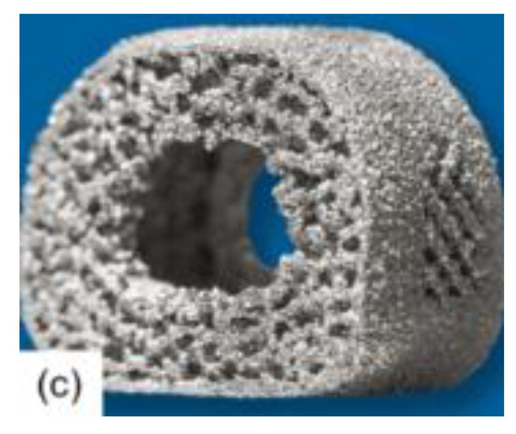
Figure 2.
Design of spinal fusion cage which the base spinal fusion cage utilized in this simulation was modeled off of [27].
Figure 2.
Design of spinal fusion cage which the base spinal fusion cage utilized in this simulation was modeled off of [27].
Disclaimer/Publisher’s Note: The statements, opinions and data contained in all publications are solely those of the individual author(s) and contributor(s) and not of MDPI and/or the editor(s). MDPI and/or the editor(s) disclaim responsibility for any injury to people or property resulting from any ideas, methods, instructions or products referred to in the content. |
© 2024 by the authors. Licensee MDPI, Basel, Switzerland. This article is an open access article distributed under the terms and conditions of the Creative Commons Attribution (CC BY) license (http://creativecommons.org/licenses/by/4.0/).
Copyright: This open access article is published under a Creative Commons CC BY 4.0 license, which permit the free download, distribution, and reuse, provided that the author and preprint are cited in any reuse.


