
Submitted:
04 September 2025
Posted:
05 September 2025
You are already at the latest version
Abstract
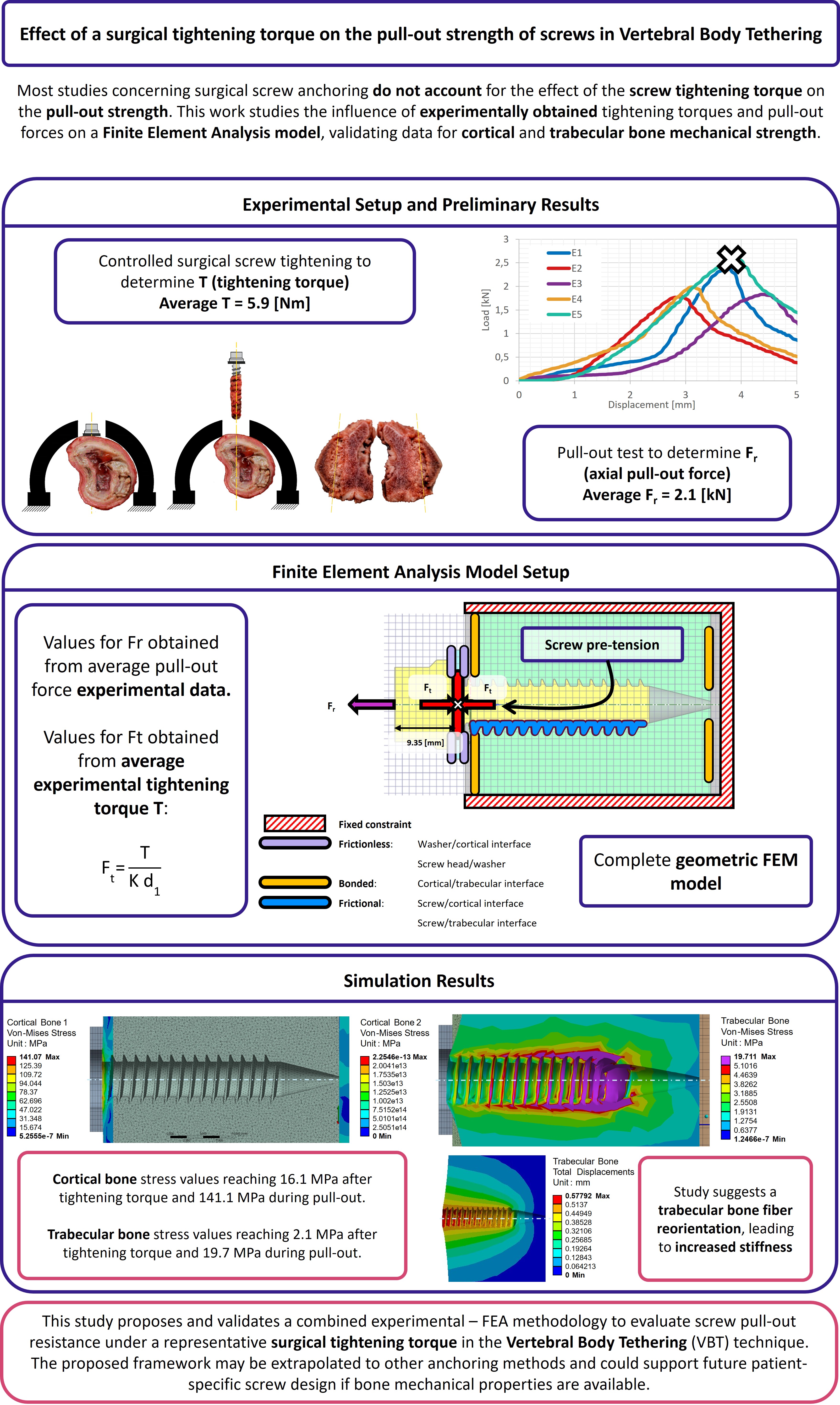
Background/Objectives: Screw loosening and vertebral fractures remain common after vertebral body tethering (VBT). Because tightening torque sets screw preload, its biomechanical effect warrants explicit modeling. In this paper, a Finite Element (FE) model, supported by ex-vivo porcine vertebrae tests, was developed and validated that incorporates torque-induced pre-tension to quantify vertebral stress, aiming toward customizable VBT planning. Methods: An FE model with pre-tension and axial extraction failure was parameterized using ex vivo tests on five porcine vertebrae. A laterally inserted surgical screw in each specimen was tightened to 5.9±0.80 [N·m]. Axial extraction produced failure loads of 2.1±0.31 [kN]. This is also considered in the FE model to validate the failure scenario. Results: Torque alone generated peak von Mises stresses of 16.1 [MPa] (cortical) and 2.1 [MPa] (trabecular), lower than prior reports. With added axial load, peaks rose to 141.1 [MPa] and 19.7 [MPa], exceeding typical ranges. However, predicted failure agreed with experiments, showing 0.58 [mm] displacement and a conical displacement distribution around the washer. Conclusions: Modeling torque-induced pre-tension is essential to reproduce realistic stress states and anchor failure in VBT. The framework enables patient-specific assessment (bone geometry/density) to recommend safe tightening torques, potentially reducing screw loosening and early fractures.
Keywords:
spine surgery
; scoliosis
; vertebral body tethering
; tightening torque
; pull-out strength
; finite element method
1. Introduction
The Vertebral Body Tethering (VBT) technique is an innovative surgical approach for correcting idiopathic scoliosis in adolescents [1]. The anchorage system involves a surgical screw and a washer inserted into the vertebral body through the lateral convex side. These anchorage systems are subsequently tensioned using a polyethylene terephthalate cord connecting the screw heads, which reduces spinal deformity and halts its progression [1]. Clinical follow-up studies over more than two years [2,3] have demonstrated improvements in Cobb angles ranging from to using the VBT technique, confirming its effectiveness in improving patient outcomes and ensuring safety during treatment [4,5,6,7,8,9,10,11,12,13].
Unlike spinal fusion techniques, VBT has been experimentally shown to preserve vertebral motion, including flexion, extension, axial rotation, and lateral bending stability [1,3,14]. Additionally, it accommodates vertebral growth, with differential growth observed in thoracic vertebrae: the concave side grew by compared to 1.5 ± 2.3 on the convex side [15]. Despite these clinical successes, the lack of computational models for evaluating the effects of VBT has been highlighted [1,3,14,16,17,18,19,20]. For instance, the numerical study by Nicolini et al. [21] examined VBT effects with cord tensions up to but did not account for tightening torque, a factor that significantly influences postoperative biomechanical loading. Therefore, more robust computational models validated against experimental data are needed to accurately understand VBT mechanics.
Among previous works, biomechanical studies have reported the forces that vertebrae endure during surgery and the postoperative behaviour of patients in motion [15]. Proper control of these forces prevents complications such as overcorrection that might affect the lungs, implant loosening, cord failure, or vertebral fracture [3,14,15]. Improvements in screw design, anchoring typologies, and better insertion orientation have been proposed to mitigate these issues [16,17,18]. These forces also participate in screw loosening, a critical concern in surgical fixation. Implant treatments generally show failure rates of 5 to , primarily associated with loosening [22].
Screw loosening occurs in two stages. First, cyclic loading causes bone wear at the screw-bone interface, reducing the existing preload due to friction between the thread and bone. In the second stage, this loss of preload exacerbates the loosening due to rotational pull-out forces from external loads and vibration [17,18]. Specifically in VBT, the tension in the polyethylene terephthalate cord generates a bending moment on the spine, creating compression on the convex side and tension on the concave side of the vertebral bodies. This effect has been previously studied via Finite Element Analysis (FEA), evaluating stress distribution in vertebrae under screw pull-out forces [23,24].
A critical yet understudied factor in anchor fixation is the final tightening torque applied to screws after insertion. The effects of tightening torque in bicortical screw fixations, as in VBT, remain insufficiently explored [25]. Experimental evidence suggests that torque values inducing stresses close to of the screw’s elastic limit optimize anchor strength and reduce loosening [19]. In dental applications, proper tightening torque ensures structural stability even under masticatory pressure, preventing loosening [26]. This underscores the importance of achieving structural stiffness to minimize screw loosening in vertebral anchoring. In most current surgical techniques, tightening torque relies on the surgeon’s experience or is applied using a torque wrench following certain standards [27]. These methods introduce variability, compounded by the uncertain mechanical properties of the bone being fixed [28].
This study proposes an FEA methodology that incorporates a representative value for surgical torque and axial extraction force, both obtained from our experimental campaign conducted on porcine thoracic vertebrae under controlled conditions that simulate the insertion technique used in the Vertebral Body Tethering (VBT) procedure. Unlike other studies, this study does not seek to compare different torque levels or establish an optimal value, but rather to evaluate the mechanical behaviour of the screw-bone system under realistic surgical conditions.
2. Methodology
To facilitate the understanding of the FEA methodology developed in this study, this section first presents the experimental campaign conducted for its formulation. This approach aims to provide a clearer insight into the challenges associated with anchoring systems using surgical screws in the VBT technique and the influence of the analyzed factor, the tightening torque. Given the challenges of conducting experimental studies on human vertebrae, various authors have demonstrated that porcine spine models are the most suitable for analysing the behaviour of human thoracic vertebrae T6 to T10 [16,17], which are commonly targeted in VBT procedures. To replicate the conditions of VBT surgery in the laboratory, a methodology for sample preparation, tightening torque application, and screw pull-out testing was established. This approach aimed to simulate real surgical conditions as closely as possible. The experimental results were then used as inputs for the FEA model, ensuring its accuracy and reliability.
2.1. Sample Preparation
The preparation of all tested samples followed the procedure described below. First, a pilot hole was drilled in the centre of the lateral surface of the porcine thoracic vertebrae, extending deep enough to penetrate the first cortical layer. Next, a surgical tap with an outer diameter of and an inner diameter of was used to thread the pilot hole until reaching the second cortical wall. To ensure bicortical support, the tip of the tap was extended beyond the outer surface of the second cortical layer. After tapping, the surgical screw and the washer were inserted (Figure 1), overcoming the required insertion torque. The washer serves a dual purpose: enabling the application of tightening torque between the screw and vertebra and ensuring the correct insertion depth within the vertebral body.
Once the screw was fully inserted, the tightening torque was manually applied in a controlled manner using a torque wrench. The tightening process involved progressively increasing the torque until it stabilised. At this point, a final slight rotation of approximately 3 degrees was applied. This method aligns with the usual medical practice during surgery. If the torque value recorded after this final rotation showed no drop compared to the stabilised value, it was taken as the reference tightening torque for the test. Otherwise, the sample was discarded. A total of five samples were prepared for the pull-out tests following this procedure.
2.2. Pull-Out Test
The experimental evaluation of the axial pull-out resistance of the screws in the five samples was performed using an INSTRON universal testing machine, operating under displacement control at a speed of [29,30]. Force measurements were obtained using a load cell (class according to ISO 7500-1:2018), connected to the actuator by a spherical joint, which ensures purely axial extraction. The porcine thoracic vertebrae, prepared according to a simulated surgical protocol of the Vertebral Body Tethering (VBT) technique, were fixed to the base of the test system, as shown in Figure 2b and Figure 2c. Mechanical failure is defined as the point at which the applied load reaches its maximum value before decreasing.
Figure 2a shows the load-displacement curves for the five samples evaluated (E1–E5), with the points corresponding to the maximum load indicated. Based on these results, an average extraction force (Fr) of was obtained. This value was subsequently used as the axial load condition in the Finite Element Analysis (FEA) model, representing the clinical scenario of screw extraction after surgical tightening.
Figure 2c,d illustrate the volume of bone displaced after screw removal, observed at the end of each test. The results indicate that applying surgical torque increases the amount of bone material displaced around the screw threads, suggesting a localised stiffness effect induced by mechanical preloading. As a theoretical reference, when the tightening torque reported in previous literature and observations is not applied, the displaced volume tends to coincide with the cylindrical region defined by the external diameter of the screw (d2) [29].
This experimental methodology simulates the behaviour of the screw anchorage system used in the VBT technique under axial extraction conditions. However, these tests have limitations in quantifying damage when applying surgical torque to the ultimate failure strength. Although they provide information on the load capacity of the screw-bone interface, they do not reflect the internal distribution of stresses or the structural effects of torque on the cortical and trabecular bone before and after extraction. To overcome these limitations and gain a deeper understanding of the behaviour of the anchorage, a finite element model is developed, based on a 3D geometric representation of the screw-vertebra system.
2.3. Geometric Model
The preparation of the FEA model begins with the screw 3D modeling in ANSYS WORKBENCH 2024 R1, following the specifications detailed in the table in Figure 1. The cortical bone thickness was set to , consistent with porcine thoracic vertebrae, as determined from the tested samples. The geometry of the surgical screw and washer was also incorporated into the model, with the screw inserted laterally into the thoracic vertebra. A Boolean operation was performed to remove the bone volume occupied by the screw. It is important to note that the screw head does not rest directly on the cortical bone, which is why the washer is used.
Ideally, the vertebra 3D model would be based on DICOM (Digital Imaging and Communications in Medicine) images of a patient undergoing VBT screw placement, obtained using a CT (computed tomography) scanner. However, the FEA of the geometric model derived from tomographic images presents several challenges. These include the generation of an excessive number of surfaces and singularities, particularly at contact points, leading to prolonged simulation times and potentially incoherent results, such as unrealistically high stresses at specific nodes. For this reason, it was deemed appropriate in this study to simplify the geometric model (Figure 3) to focus on analysing the effects of tightening torque and pull-out force. The simplified model only represents the threaded length of the screw, forgoing the tip. This is done owing to the fact that the screw tip only serves as a balancing point in the case of transversal loads, and does not produce any effect in the case of pull-out loads.
2.4. Mechanical Properties
This section defines the mechanical properties of the volumes considered in the previous section (surgical screw, washer, porcine cortical bone, and trabecular bone). As supported by other authors in similar studies [1,28], both cortical and trabecular bone can be considered isotropic for FEA purposes. Accordingly, all elements in the model were assumed to exhibit elastic linear and homogeneous behaviour, with mechanical properties derived from the referenced literature, as summarised in Table 1.
2.5. Mesh
The geometry of the model and the mechanical properties of the solids were imported into ANSYS WORKBENCH. The meshing of all volumes was performed using SOLID187 10-node quadratic tetrahedrical 3D elements, which are well-suited for meshing irregular geometries, such as the surgical screw [34,35]. As shown in Table 2, the selected element size varied across geometries. Refinement tests ensured a convergence criterion of , meaning that stress values remained within this range when further refining the mesh.
2.6. Model Formulation
This Subsection will focus on the definition of load cases and boundary conditions for the presented FEA model.
2.6.1. Load Cases
Two load cases were studied in this work: screw tightening and screw pull-out. In the first case, only the tightening torque is applied on the screw, whereas in the second case, both the tightening torque and the extraction load are present.
To model the tightening torque (T), several simplifications are assumed. Simulating the physical process of applying torque and nut rotation is computationally expensive and does not improve result accuracy. Instead, a common practice in FEA modelling is replicating the shortening of the grip length (which induces a preload tension) by splitting the bolt into two sections and applying a preload at both ends [36]. This is known as a bolt pre-tension model.
In bolt pre-tension models, the bolt is represented as a cylinder divided into two halves, and two coinciding nodes (i and j) are selected at the interface of the halves. Constraint equations are then defined to link the relative motion of these nodes. By specifying the force applied to the spring connecting nodes i and j, a tensile load is introduced into both halves of the cylinder, effectively simulating the bolt pre-tension (see Figure 5).
Therefore, the bolt pre-tension condition is applied to the shaft of the surgical screw, as illustrated in Figure 5b. To apply this condition, it is essential to determine the pre-tension load induced by the tightening torque T, which is related through Equation (1), as described in [36].
where [mm] is the screw diameter, and K is a torque coefficient that can be assumed as [2]. The bolt pre-tension condition applies the load (Figure 5b) to simulate the stress state equivalent to applying the tightening torque, allowing this effect to transfer to the surrounding structures. This pre-tension condition shall be applied in a region of the screw that is not in contact with the surrounding structure to accurately model the actual loading condition applied by the fastener. In this case, this location is the screw region surrounded by the steel washer, at 9.35 [mm] from the screw head. Lastly, this simplification assumes no shear loads may be transferred in the pre-tension region, and requires the small rotation and large deflection formulations to be considered for this model. This allows slight rotational movement of the surgical screw along its axial direction under tensile loading within the cortical and trabecular bone, offering a more realistic simulation than fixing the tension direction strictly along the thread’s axial axis. For the second load case, this pre-tension stress state is maintained, and a second loading condition is then applied: the axial pull-out force on the screw (illustrated in Figure 6).
2.6.2. Boundary Conditions
The configuration of surface contacts between the various bodies can be modelled under two conditions: post-surgical and osseointegration (occurring more than four months after surgery). These conditions dictate how the internal contacts between the vertebral structures and the implant are defined. If the aim is to simulate screw extraction, it is crucial to determine whether the screw has undergone osseointegration. For an osseointegrated screw, a bonded contact type should be used to simulate the screw being adhered to the bone. Conversely, in a post-surgical scenario where osseointegration has not yet occurred, a frictional contact should be applied [37]. This post-surgical scenario is the object of study in the present work.
For the surface contacts between the threads of the titanium screw and its housing in the cortical bone, a coefficient of friction of 0.12 was applied [37]. However, for the contacts between the steel washer and the external surface of the cortical bone, as well as the screw threads and the trabecular bone, a frictionless contact was implemented. This type of contact is characterised by the absence of tangential forces, allowing the surfaces to slide over each other without resistance. This aligns with the bolt pre-tension model previously outlined, which implied no shear loads may be transferred between the screw threads and the trabecular bone. In the normal direction, the surfaces can separate but cannot penetrate each other. In the case of the contact between the washer and the cortical bone, this approach is particularly useful, as it may simulate well-lubricated interfaces where friction can be neglected [38]. In this clinical scenario, the lubricant is blood, making this condition a realistic approximation of actual surgical conditions.
As for the cortical-trabecular bone interface, the surface contact between these structures is defined as bonded, as these layers do not separate. The outer fixed constraint should be positioned sufficiently far from the screw’s insertion site–approximately 11 times the screw’s outer diameter–to define a fixed boundary condition and facilitate numerical calculations. The defined contact conditions are illustrated in Figure 6.
The described FEM model provides the von Mises stress values within the elements of the vertebral system, enabling the identification of potential anchorage failures.
3. Results and Discussion
Given the availability of experimental pull-out test results, this section compares the values obtained under identical loading conditions in both the experimental tests and the simulation model. The experimental tightening torque values from the five samples (E1–E5) were: 7 [Nm] (E1), 5.2 [Nm] (E2), 6.5 [Nm] (E3), 5.4 [Nm] (E4), and 5.4 [Nm] (E5), with an average of 5.9 [Nm]. Substituting this T value into Equation (1) yields a pre-tension force of [N], which was applied as the preload in the computational model. For the pull-out force, a value of [kN] was used, as discussed previously in the Methodology.
Subsequently, both load cases are separately analysed and discussed. As a reminder, load case 1 focuses on the effect of tightening torque, whereas load case 2 comprehends both the tightening torque and a pull-out load, simulating the clinical failure scenario arising from critical extraction loads.
3.1. Load Case 1: Effect of Tightening Torque
The stress distribution generated by was analysed separately for the trabecular and cortical bone. This stress distribution arises primarily from the compression exerted by the screw threads on the bone structures. Under this load, the bone-screw interface’s rigidity is enhanced, reducing the likelihood of loosening under static and dynamic loads.
Figure 7 shows the von Mises stress distribution in the trabecular bone resulting from the tightening torque. The stress concentration is homogeneously scattered throughout the threads, with the maximum value reached in the last thread. This is the expected behavior of the trabecular bone under a tightening torque, as the screw pulls the trabecular bone threading against the cortical bone on the left-hand side. The maximum stress value reached is 2.1 [MPa], which is below the resistance range of 5 – 15 [MPa] shown in Table 1. Therefore, the applied tightening torque does not compromise the trabecular bone structure.
Figure 8 shows the stress values in Cortical Bone 1 (screw head side, left-hand side), as well as Cortical Bone 2 (screw tip side, right-hand side). The screw preload induces von Mises stresses only in the screw head side cortical layer, as it is the layer which supports the trabecular bone preload. This stress value reaches a maximum of 16.1 [MPa], which is well below the cortical bone strengths reported in Table 1. This indicates that failure during the tightening stage occurs due to a trabecular bone threading failure, since the cortical layer is under-stressed. Cortical bone 2, on the other hand, does not contribute to the preload stage. This aligns with the notions of surgical and experimental procedure, as the screw tip should not perform any function for tightening or pull-out purposes.
As a last remark for von Mises stress distributions for the tightening torque load case, Figure 9 shows the stress values across the entire model. The maximum stress value is located in the screw thread, and reaches a value of 58.7 [MPa]. This is the expected behavior for the anchorage, where the load is mainly withstood by the stiffest element (i.e., the titanium screw). The complete stress diagram also shows that the stress is mainly distributed in the vertebra across the first cortical bone layer, in the region close to the steel washer. This result does not inform about the trabecular bone fibers reorientation due to the effect of tightening the screw. This will be shown in SubSection 3.2, where displacements are discussed.
3.2. Load Case 2: Effect of Pull-Out Load
The primary purpose of the simulation under pull-out loading is to verify the von Mises stress levels that indicate vertebral failure, incorporating the tightening torque. These stress values should align with the ranges reported in specialised literature, confirming that the yield stress has been exceeded and failure has occurred, consistent with observations in the experimental campaign. Figure 10 shows the von Mises stress values in the trabecular bone after applying the experimental pull-out failure load. The maximum stress is 19.7 [MPa], which falls outside the range reported in the literature (5 – 15 [MPa]).
This may be explained by the reorientation of trabecular bone fibers caused by tightening. This is further validated in Figure 11 and Figure 12, where this reorientation is seen by means of material displacements in the trabecular bone.
In this Figure, a conic shape can be observed, indicating a reorganisation of trabecular fibers, from the end of the trabecular threading towards the steel washer. This reorganisation causes an increase of bone stiffness [26]. This conic shape aligns with the pull-out behavior observed in the experimental campaign, where the volume displaced by the screw during extraction is greater than the threading bounding cylinder. Additionally, Figure 11 and Figure 12 exhibit a maximum displacement value of 0.58 [mm].
This shows good agreement with experimental results when the vertebrae settling in the testing fixture is accounted for. Thus, the model accurately reflects the failure of the trabecular structure under the applied pull-out load. The simulation also reveals that stress distribution is highest at the final crests of the trabecular threading, as the trabecular bone at the end has not been compacted sufficiently by the previously applied tightening torque and subsequent extraction force.
Regarding the cortical bones, applying the tightening torque and extraction load, the stress levels are observed in the Figure 13. The maximum stress value is 141.1 [MPa], which is slightly higher than the values reported in the literature (Table 1). As in the case of the trabecular bone, the pre-tension increases the internal stiffness of the bone sections, making it significantly more difficult to detach the structures during the pull-out load. This effect was not accounted for in previous studies. The reference loads from the literature are based on purely axial extraction without considering additional effects, such as those introduced by pre-tension and other factors analysed in this study.
Overall, this model suggests that the pull-out failure occurs when the trabecular threading collapses, and then the cortical layer fails to withstand by itself the stresses originated by the screw extraction. This is the expected clinical scenario, and the observation made during the experimental campaign. The numerical methodology applied replicates the experimental scenario using FEA to quantify stress levels in the surrounding structures. This approach can be utilised for clinical exploration under varying boundary conditions that may lead to vertebral failure, enabling further investigations and optimisations.
3.3. Limitations of the model and future prospects
One of the limitations of this study is the use of an isotropic and linear model to represent bone tissue, which does not fully reflect its heterogeneity or post-elastic behaviour. However, this simplification has been validated in previous studies [36,37,39] for analyses where the main focus is on stress distribution and the initial mechanical behaviour of the fastening system. In addition, it improves computational stability, especially in simulations involving complex contact with threaded geometry.
It is recognised that the incorporation of heterogeneous models derived from bone density maps could provide greater accuracy, particularly for assessing the evolution of bone damage or the risk of implant loosening. This line of research is proposed as future work.
4. Conclusions
An experimental campaign to determine the pull-out force in porcine thoracic vertebrae using the VBT technique was presented. Through the described numerical methodology, the potential vertebral damage was quantified under an average tightening torque of [Nm]. Stress levels confirmed the absence of failure in the vertebral bones, ensuring the safety of proceeding with the screw pull-out tests. Additionally, the average maximum pull-out force was determined to be [kN] when the final tightening torque was applied to the assembly. As a result of the proposed methodology, the maximum stress levels in the cortical and trabecular bone were identified, which exceed those reported in specialised literature.
This study shows FEA may provide a deeper understanding of the vertebral system after the VBT technique when subjected to axial pull-out loads. Although other forces are present during movement activities, the final tightening torque is considered the most critical, as it directly influences the performance of the assembly. However, even with a well-developed numerical model, failing to account for the screw pre-tension applied through the final tightening torque post-surgery could result in lower stiffness levels. This outcome would not align with the conditions and findings established in the present study, where adequate screw pre-tension is crucial for optimal biomechanical behavior.
One of the key outcomes of this computational study is its ability to define safe ranges of tightening torque that can be applied without causing vertebral damage once the model is calibrated. The stress distribution on the vertebral body was examined, a variable parameter that depends on the surgeon’s technique and expertise during the procedure. Controlling the tightening torque levels would prevent early failure in the vertebra. The value used in this study, [Nm], did not cause damage. From this perspective, it is recommended that tightening torque values remain below this threshold during surgical screw fixation. Additionally, tightening torque plays a key role in increasing the trabecular and cortical bone stiffness in the anchorage, as demonstrated by the results provided in the present study.
Limitations persist in simulation models developed using reverse engineering from CT scans. In this study, a geometric model of a human thoracic vertebra derived from a tomographic image was used. While this approach is expected to offer a closer approximation to real conditions, incorporating additional vertebral components not only complicates model construction but also significantly increases the computational load. As a result, the outcomes were suboptimal, with excessive stress concentrations arising from the reconstruction process, making it challenging to interpret the cortical-trabecular interaction. Therefore, a simplified homologous model was constructed to better align with the experimental conditions and enable the application of FEA effectively. In this simplified model, the mechanical behavior of the surgical screw was not considered, as no failure was observed during the tests.
However, the authors believe that understanding the behavior of the surgical screw becomes relevant due to variations in parameters such as diameter, pitch, length, and material, as stated by previous studies [27,28,29,30]. Furthermore, the experimental campaign demonstrated that the use of large-dimension screws can trigger vertebral failure due to the substantial volume inserted. Such failures may originate from factors like bone porosity, existing pathologies, and the patient’s age [37,40], and may be mitigated by previously simulating the surgical scenario.
A second limitation is that the cortical layer was explicitly dimensioned based on the experimental study. Measurements of the cortical thickness in the porcine samples were taken, yielding an average value. While this thickness could influence the final results, the stress values obtained correlate well with those reported in the literature. Additionally, it is computationally feasible to identify the point of structural failure by parametrising the thickness of the cortical walls, providing further insight into their role in biomechanical behaviour. In addition, the mechanical properties of the porcine specimen were sourced from various finite element studies. The wide range of values considered poses a limitation that must be accounted for when representing different stress states. Replacing the numerical methodology in this study with the mechanical properties of human thoracic vertebrae could provide a correlation coefficient, demonstrating the relevance and applicability of the simulation method to both specimens. This would enhance the study’s relevance and broaden its scope for clinical applications.
In conclusion, this numerical methodology provides positive contributions for the prognosis, preventive management, and therapeutic strategies for spinal failures. Additionally, the study supports the use of porcine thoracic specimens in orthopaedic biomechanical research.
Funding
There are no financial conflicts of interest to disclose.
Author Contributions: Freddy Patricio Moncayo-Matute
: Conceptualization, Data curation, Methodology, Resources, Writing – original draft. Rafael Claramunt: Formal analysis, Investigation, Validation. Alvaro Guzman-Bautista: Software, Visualization, Writing – original draft, Writing – review & editing. Paul Bolivar Torres-Jara: Data curation, Validation. Enrique Chacon-Tanarro: Conceptualization, Project Administration, Supervision, Writing – review & editing.
Institutional Review Board Statement
Not applicable. The study did not involve human participants or procedures on live animals. Only post-mortem porcine vertebrae supplied by a licensed food-industry provider, originally intended for human consumption, were used; therefore, in accordance with Ecuadorian Resolution 0227 (Agrocalidad, 08/11/2021), ethics committee approval was not required for their use in mechanical testing. No specimen returned to the food chain, and institutional biosafety procedures were followed.
Informed Consent Statement
Not applicable.
Data Availability Statement
Data is included in the article/supplementary material is referenced in the article.
Acknowledgments
The authors would like to thank the Mechanical Engineering Dept., ETSI Industriales, Universidad Politécnica de Madrid for their support throughout the development of this research.
Conflicts of Interest
The authors declare no conflict of interest.
References
- Ames, R.J.; Samdani, A.F.; Betz, R.R. Anterior scoliosis correction in immature patients with idiopathic scoliosis. Oper. Tech. Orthop. 2016, 26, 247–257. [Google Scholar] [CrossRef]
- Driscoll, M.; Aubin, C.E.; Moreau, A.; Parent, S. Biomechanical comparison of fusionless growth modulation corrective techniques in pediatric scoliosis. Med. Biol. Eng. Comput. 2011, 49, 1437–1445. [Google Scholar] [CrossRef]
- Cunin, V. Early-onset scoliosis–current treatment. Orthop. Traumatol. Surg. Res. 2015, 101, S109–S118. [Google Scholar] [CrossRef]
- Fairhurst, H.; Little, J.P.; Adam, C.J. Intra-operative measurement of applied forces during anterior scoliosis correction. Clin. Biomech. 2016, 40, 68–73. [Google Scholar] [CrossRef]
- Gould, S.L.; Cristofolini, L.; Davico, G.; Viceconti, M. Computational modelling of the scoliotic spine: a literature review. Int. J. Numer. Methods Biomed. Eng. 2021, 37, e3503. [Google Scholar] [CrossRef] [PubMed]
- Cobetto, N.; Parent, S.; Aubin, C.E. 3D correction over 2 years with anterior vertebral body growth modulation: a finite element analysis of screw positioning, cable tensioning and postoperative functional activities. Clin. Biomech. 2018, 51, 26–33. [Google Scholar] [CrossRef] [PubMed]
- Yaszay, B.; Doan, J.D.; Parvaresh, K.C.; Farnsworth, C.L. Risk of Implant Loosening after Cyclic Loading of Fusion-less Growth Modulation Techniques: Nitinol Staples vs Flexible Tether. Spine 2016. [Google Scholar] [CrossRef]
- Brink, R.C.; Schlösser, T.P.; van Stralen, M.; Vincken, K.L.; Kruyt, M.C.; Hui, S.C.; Viergever, M.A.; Chu, W.C.; Cheng, J.C.; Castelein, R.M. Anterior-posterior length discrepancy of the spinal column in adolescent idiopathic scoliosis—a 3D CT study. Spine J. 2018, 18, 2259–2265. [Google Scholar] [CrossRef]
- Helenius, I.; Remes, V.; Yrjönen, T.; Ylikoski, M.; Schlenzka, D.; Helenius, M.; Poussa, M. Harrington and Cotrel-Dubousset instrumentation in adolescent idiopathic scoliosis: long-term functional and radiographic outcomes. J. Bone Joint Surg. Am. 2003, 85, 2303–2309. [Google Scholar] [CrossRef]
- Helenius, L.; Diarbakerli, E.; Grauers, A.; Lastikka, M.; Oksanen, H.; Pajulo, O.; Löyttyniemi, E.; Manner, T.; Gerdhem, P.; Helenius, I. Back pain and quality of life after surgical treatment for adolescent idiopathic scoliosis at 5-year follow-up: comparison with healthy controls and patients with untreated idiopathic scoliosis. J. Bone Joint Surg. Am. 2019, 101, 1460–1466. [Google Scholar] [CrossRef]
- Marks, M.C.; Bastrom, T.P.; Petcharaporn, M.; Shah, S.A.; Betz, R.R.; Samdani, A.; Lonner, B.; Miyanji, F.; Newton, P.O. The effect of time and fusion length on motion of the unfused lumbar segments in adolescent idiopathic scoliosis. Spine Deform. 2015, 3, 549–553. [Google Scholar] [CrossRef]
- Parsch, D.; Gaertner, V.; Brocai, D.; Carstens, C. The effect of spinal fusion on the long-term outcome of idiopathic scoliosis: a case-control study. J. Bone Surg. Brit. 2001, 83, 1133–1136. [Google Scholar] [CrossRef] [PubMed]
- Keenan, B.E.; Izatt, M.T.; Askin, G.N.; Labrom, R.D.; Pettet, G.J.; Pearcy, M.J.; Adam, C.J. Segmental torso masses in adolescent idiopathic scoliosis. Clin Biomech. 2014, 29, 773–779. [Google Scholar] [CrossRef] [PubMed]
- Desroches, G.; Aubin, C.E.; Sucato, D.J.; Rivard, C.H. Simulation of an anterior spine instrumentation in adolescent idiopathic scoliosis using a flexible multi-body model. Med. Biol. Eng. Comput. 2007, 45, 759–768. [Google Scholar] [CrossRef] [PubMed]
- Wall, E.J.; Jain, V.V.; Crawford, A.H.; Bylski-Austrow, D.I.; Reynolds, J.E. Spine growth modulation in early adolescent idiopathic scoliosis: prospective US FDA IDE pilot study of titanium clip-screw implant at two to five years. Spine Deform. 2019, 7, 899–909. [Google Scholar] [CrossRef]
- Hamad, A.; Ahmed, E.B.; Tsirikos, A.I. Adolescent idiopathic scoliosis: a comprehensive approach to aetiology, diagnostic assessment and treatment. Orthop. Trauma 2017, 31, 343–349. [Google Scholar] [CrossRef]
- Cobetto, N.; Aubin, C.E.; Parent, S. Surgical planning and follow-up of anterior vertebral body growth modulation in pediatric idiopathic scoliosis using a patient-specific finite element model integrating growth modulation. Spine Deform. 2018, 6, 344–350. [Google Scholar] [CrossRef]
- Burwell, R.G.; Dangerfield, P.H.; Moulton, A.; Grivas, T.B. Adolescent idiopathic scoliosis (AIS), environment, exposome and epigenetics: a molecular perspective of postnatal normal spinal growth and the etiopathogenesis of AIS with consideration of a network approach and possible implications for medical therapy. Scoliosis 2011, 6, 1–20. [Google Scholar] [CrossRef]
- Fogel, G.R.; Parikh, R.D.; Ryu, S.I.; Turner, A.W. Biomechanics of lateral lumbar interbody fusion constructs with lateral and posterior plate fixation. J. Neurosurg. Spine 2014, 20, 291–297. [Google Scholar] [CrossRef]
- Cappuccino, A.; Cornwall, G.B.; Turner, A.W.; Fogel, G.R.; Duong, H.T.; Kim, K.D.; Brodke, D.S. Biomechanical analysis and review of lateral lumbar fusion constructs. Spine 2010, 35, S361–S367. [Google Scholar] [CrossRef]
- Nicolini, L.F.; Beckmann, A.; Laubach, M.; Hildebrand, F.; Kobbe, P.; de Mello Roesler, C.R.; Fancello, E.A.; Markert, B.; Stoffel, M. An experimental-numerical method for the calibration of finite element models of the lumbar spine. Med. Eng. Phys. 2022, 107, 103854. [Google Scholar] [CrossRef] [PubMed]
- Jung, R.E.; Pjetursson, B.E.; Glauser, R.; Zembic, A.; Zwahlen, M.; Lang, N.P. A systematic review of the 5-year survival and complication rates of implant-supported single crowns. Clin. Oral Implants Res. 2008, 19, 119–130. [Google Scholar] [CrossRef] [PubMed]
- Cleek, T.M.; Reynolds, K.J.; Hearn, T.C. Effect of screw torque level on cortical bone pullout strength. J. Orthop. Trauma 2007, 21, 117–123. [Google Scholar] [CrossRef] [PubMed]
- Krishnan, V.; Varghese, V.; Kumar, G.S. Comparative analysis of effect of density, insertion angle and reinsertion on pull-out strength of single and two pedicle screw constructs using synthetic bone model. Asian Spine J. 2016, 10, 414. [Google Scholar] [CrossRef]
- Hsieh, M.K.; Lee, D.M.; Li, Y.D.; Peng, C.C.; Tsai, T.T.; Lai, P.L.; Chen, W.P.; Tai, C.L. Biomechanical evaluation of position and bicortical fixation of anterior lateral vertebral screws in a porcine model. Sci. Rep. 2023, 13, 454. [Google Scholar] [CrossRef]
- Geng, J.P.; Tan, K.B.; Liu, G.R. Application of finite element analysis in implant dentistry: a review of the literature. J. Prosthet. Dent. 2001, 85, 585–598. [Google Scholar] [CrossRef]
- Singh, H.; Sonkesriya, S.; Patel, B.J.; Rathod, V.; Gupta, B.; Vyas, T.; Sawhney, A.; Makkad, R.S. Implant abutment using hand drivers versus torque wrench. Bioinf. 2023, 19, 221. [Google Scholar] [CrossRef]
- Song, C.H.; Park, J.S.; Choi, B.W.; Lee, J.S.; Lee, C.S. Computational investigation for biomechanical characteristics of lumbar spine with various porous Ti–6Al–4V implant systems. Appl. Sci. 2021, 11, 8023. [Google Scholar] [CrossRef]
- Le Cann, S.; Cachon, T.; Viguier, E.; Miladi, L.; Odent, T.; Rossi, J.M.; Chabrand, P. Pedicle screw fixation study in immature porcine spines to improve pullout resistance during animal testing. PloS One 2015, 10, e0127463. [Google Scholar] [CrossRef]
- Conrad, B.P.; Cordista, A.G.; Horodyski, M.; Rechtine, G.R. Biomechanical evaluation of the pullout strength of cervical screws. Clin. Spine Surg. 2005, 18, 506–510. [Google Scholar] [CrossRef]
- Kocis, J.; Navrat, T.; Florian, Z.; Wendsche, P.; et al. Biomechanical testing of spinal segment fixed by thoracolumbar spine locking plate on the swine lumbar spine. Biomed. Pap. Med. Fac. Univ. Palacky Olomouc Czech Repub. 2010, 154, 345–354. [Google Scholar] [CrossRef]
- Lv, Q.B.; Gao, X.; Pan, X.X.; Jin, H.M.; Lou, X.T.; Li, S.M.; Yan, Y.Z.; Wu, C.C.; Lin, Y.; Ni, W.F.; et al. Biomechanical properties of novel transpedicular transdiscal screw fixation with interbody arthrodesis technique in lumbar spine: A finite element study. J. Orthop. Transl. 2018, 15, 50–58. [Google Scholar] [CrossRef]
- Zanetti, E.M.; Salaorno, M.; Grasso, G.; Audenino, A.L. Parametric analysis of orthopedic screws in relation to bone density. Open Med. Inform. J. 2009, 3, 19. [Google Scholar] [CrossRef] [PubMed]
- Carson, W.L.; Duffield, R.C.; Arendt, M.; Ridgely, B.J.; Gaines Jr, R.W. Internal forces and moments in transpedicular spine instrumentation the effect of pedicle screw angle and transfixation—the 4R-4Bar linkage concept. Spine 1990, 15, 893–901. [Google Scholar] [CrossRef] [PubMed]
- Fan, W.; Guo, L.X.; Zhao, D. Stress analysis of the implants in transforaminal lumbar interbody fusion under static and vibration loadings: a comparison between pedicle screw fixation system with rigid and flexible rods. J. Mater. Sci. Mater. Med. 2019, 30, 1–10. [Google Scholar] [CrossRef] [PubMed]
- Burguete, R.L.; Johns, R.B.; King, T.; Patterson, E.A. Tightening characteristics for screwed joints in osseointegrated dental implants. J. Prosthet. Dent. 1994, 71, 592–599. [Google Scholar] [CrossRef]
- Chen, S.I.; Lin, R.M.; Chang, C.H. Biomechanical investigation of pedicle screw–vertebrae complex: a finite element approach using bonded and contact interface conditions. Med. Eng. Phys. 2003, 25, 275–282. [Google Scholar] [CrossRef]
- Andreucci, C.A.; Fonseca, E.M.M.; Jorge, R.N. Bio-lubricant Properties Analysis of Drilling an Innovative Design of Bioactive Kinetic Screw into Bone. Designs 2023, 7. [Google Scholar] [CrossRef]
- Andreucci, C.A.; Fonseca, E.M.; Jorge, R.N. Bio-lubricant properties analysis of drilling an innovative design of bioactive kinetic screw into bone. Designs 2023, 7, 21. [Google Scholar] [CrossRef]
- Bonney, H.; Colston, B.; Goodman, A. Regional variation in the mechanical properties of cortical bone from the porcine femur. Med. Eng. Phys. 2011, 33, 513–520. [Google Scholar] [CrossRef]
Figure 1.
Anchoring elements nomenclature and dimensions.
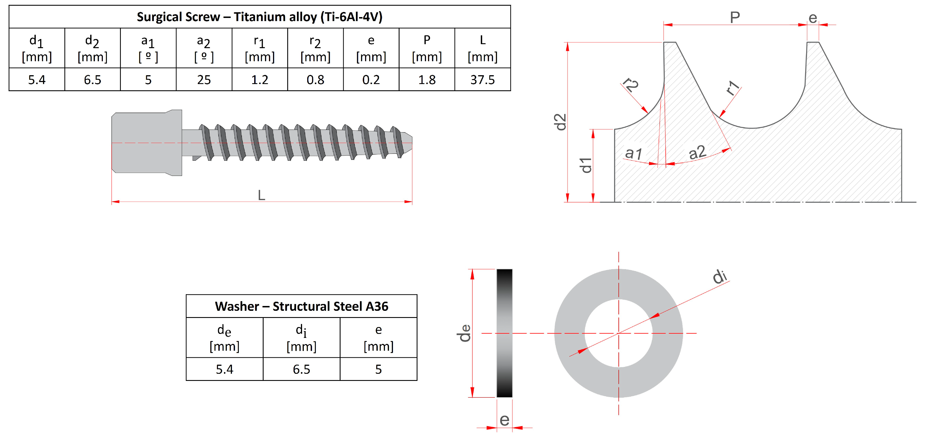
Figure 2.
Results of the pull-out test: (a) Experimental pull-out load [kN]-displacement [mm] results. (b) Lateral positioning of the screw within the vertebra. (c) Screw extraction, showing bone debris adhered to the screw threads. (d) Vertebral cross-section and evacuated volume following the test (sample E1).
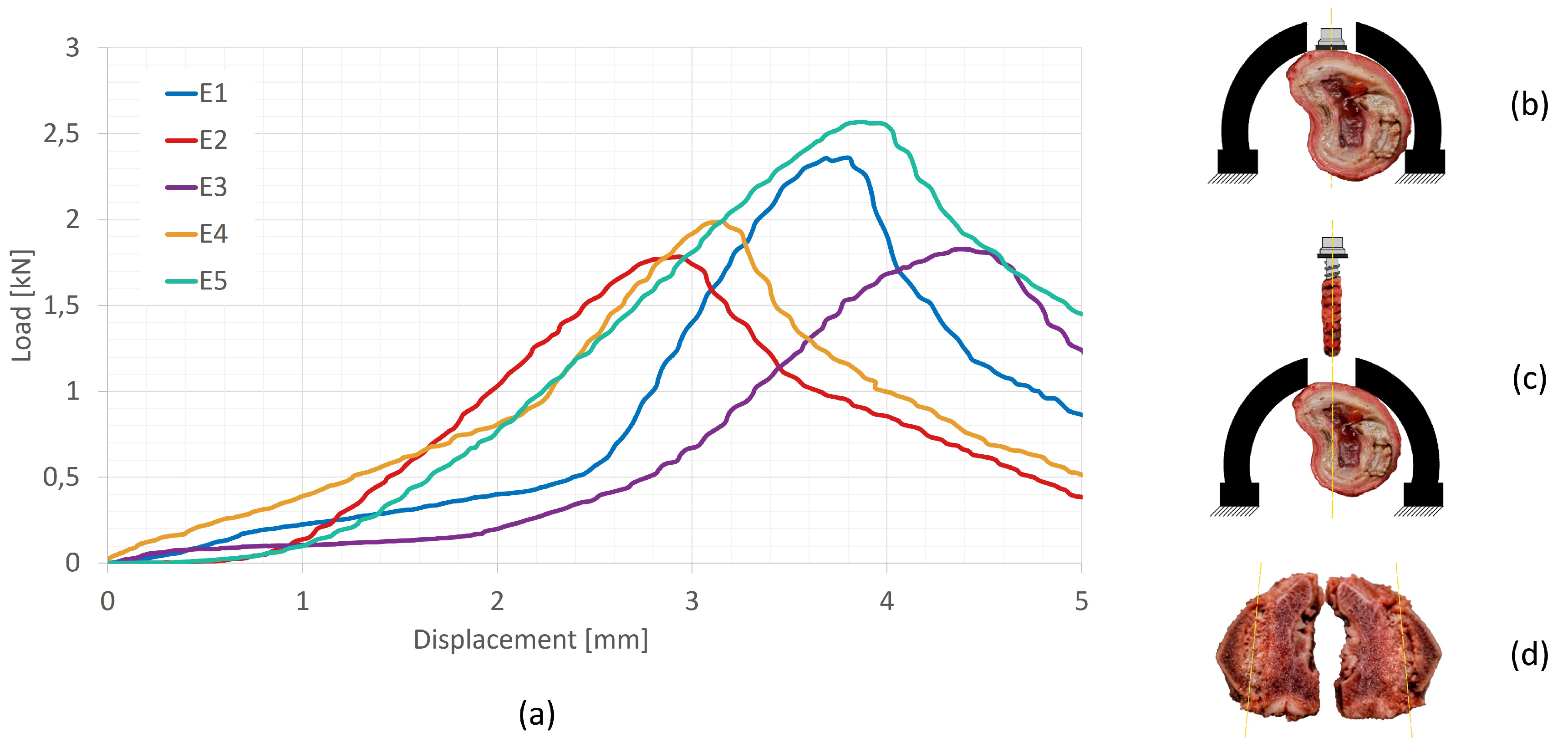
Figure 3.
Finite Element Analysis, simplified model done in the SpaceClaim ANSYS submodule. The area of study is a wide square.
Figure 3.
Finite Element Analysis, simplified model done in the SpaceClaim ANSYS submodule. The area of study is a wide square.
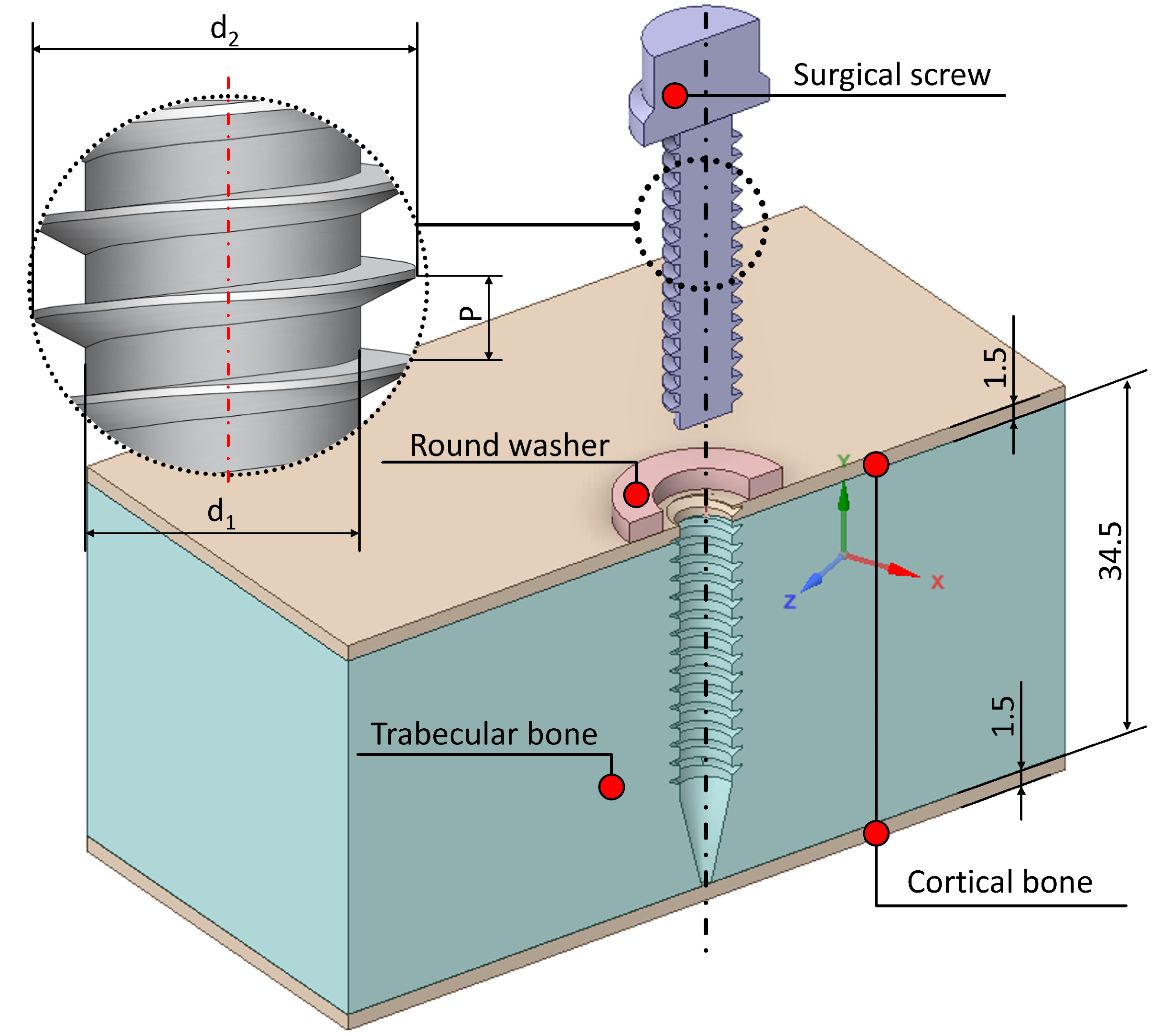
Figure 4.
Anchorage system and vertebral model mesh. (a) Isometric view of the steel washer, cortical bones 1 and 2, trabecular bone, and threaded hole. (b) Cross-section of the previous view. (c) Detail of the screw head, locating the steel washer and the cortical bone 1. (d) Screw geometry and mesh.
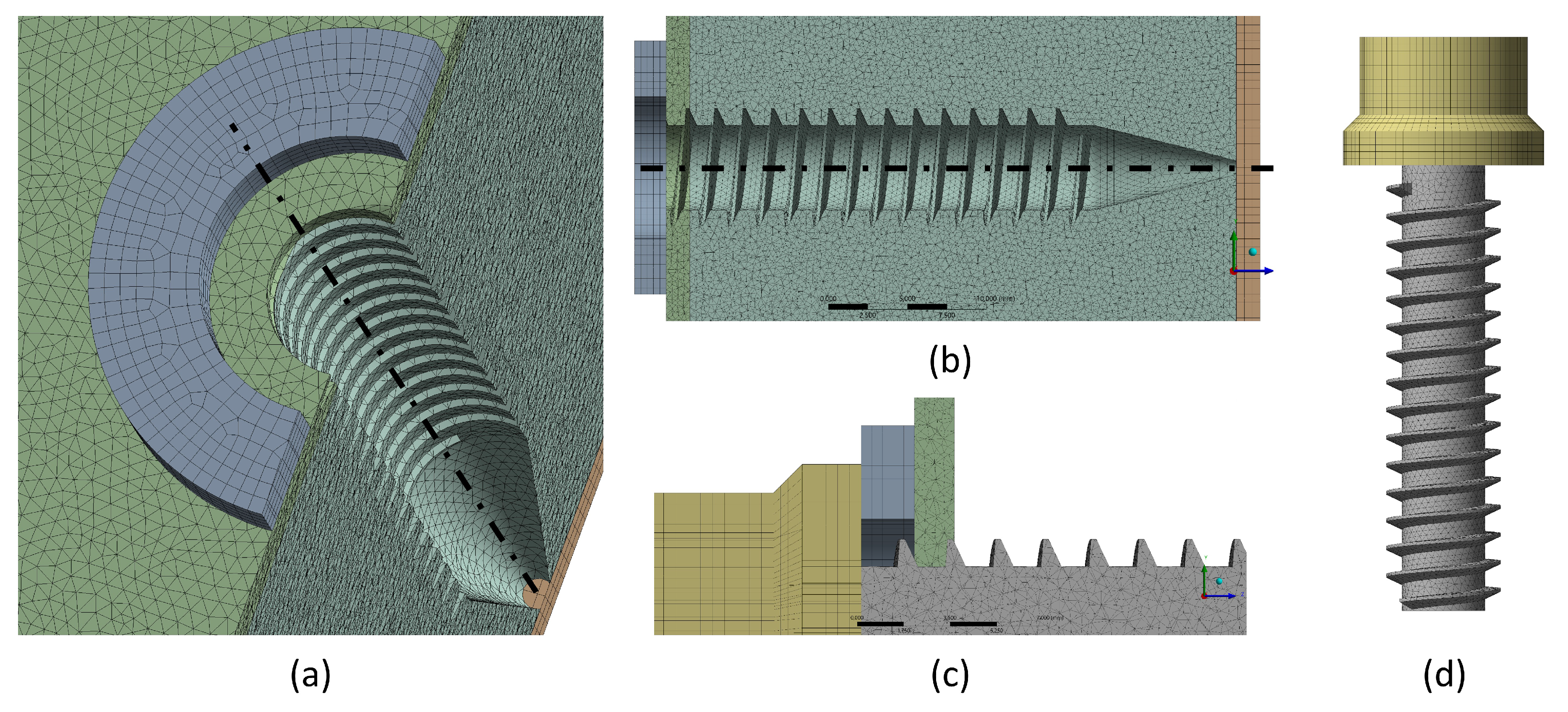
Figure 5.
Bolt pre-tension model. (a) Numerical modelling of the bolt pre-tension. (b) Detail of the screw pre-tension.
Figure 5.
Bolt pre-tension model. (a) Numerical modelling of the bolt pre-tension. (b) Detail of the screw pre-tension.
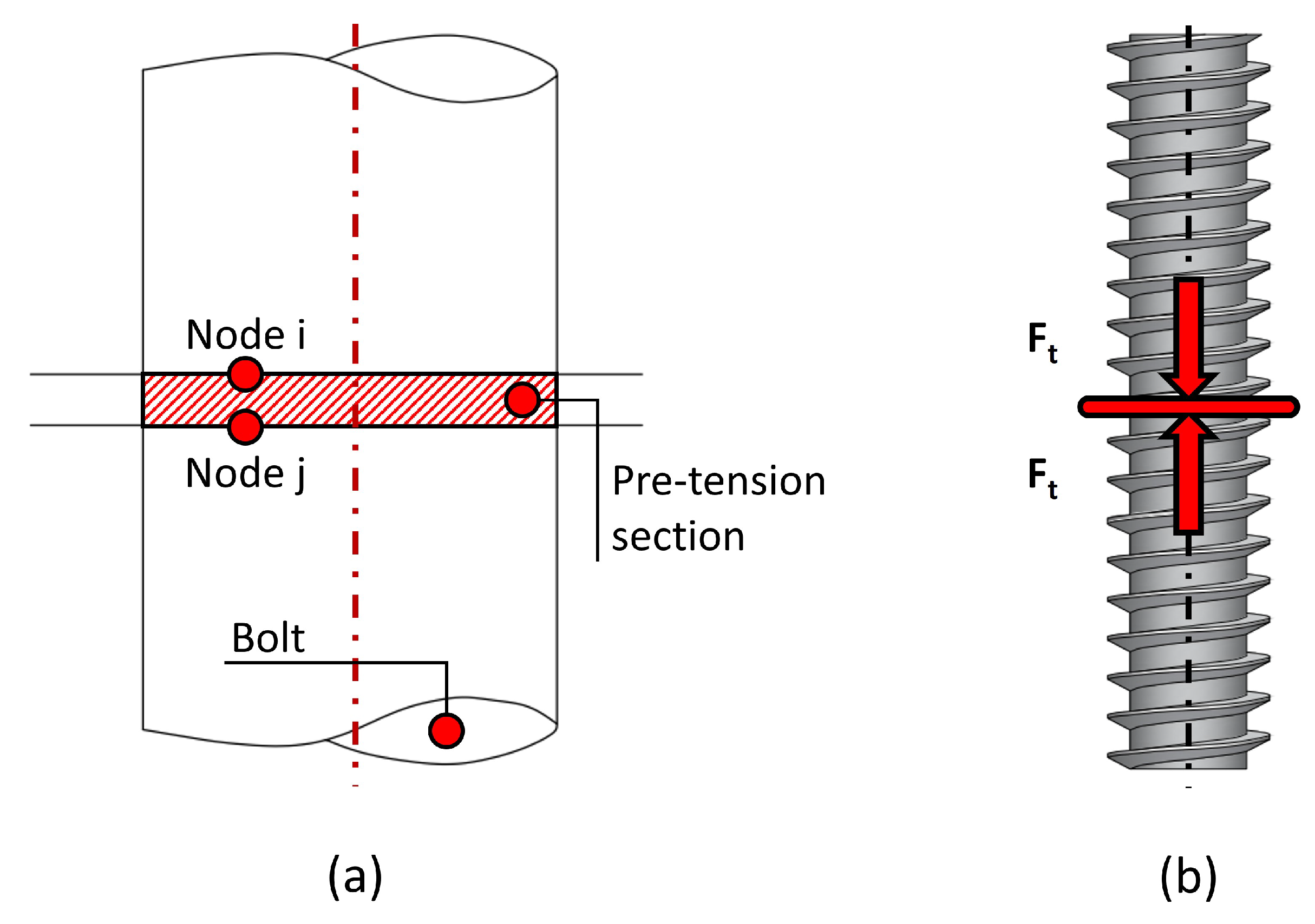
Figure 6.
Vertebral system boundary conditions, front view of the screw pull-out (legend in the right-hand side of the Figure). Of note, the pre-tension location is indicated with a white cross sign.
Figure 6.
Vertebral system boundary conditions, front view of the screw pull-out (legend in the right-hand side of the Figure). Of note, the pre-tension location is indicated with a white cross sign.
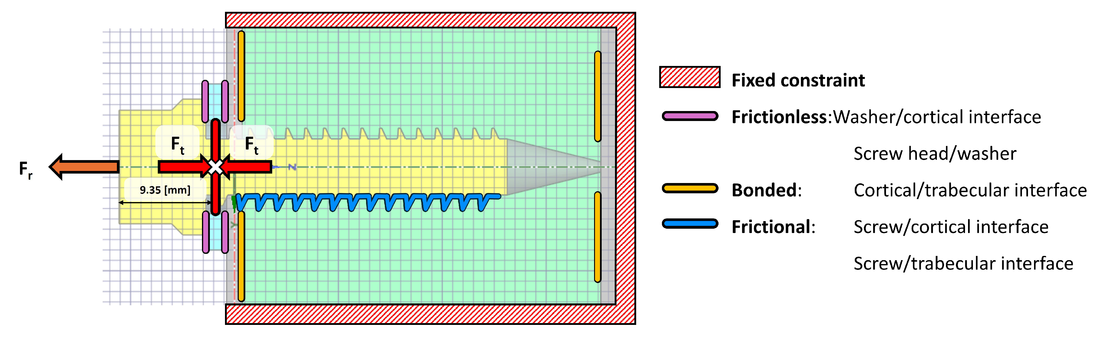
Figure 7.
Stress distribution in trabecular bone, cross-sectional view of the threaded area.
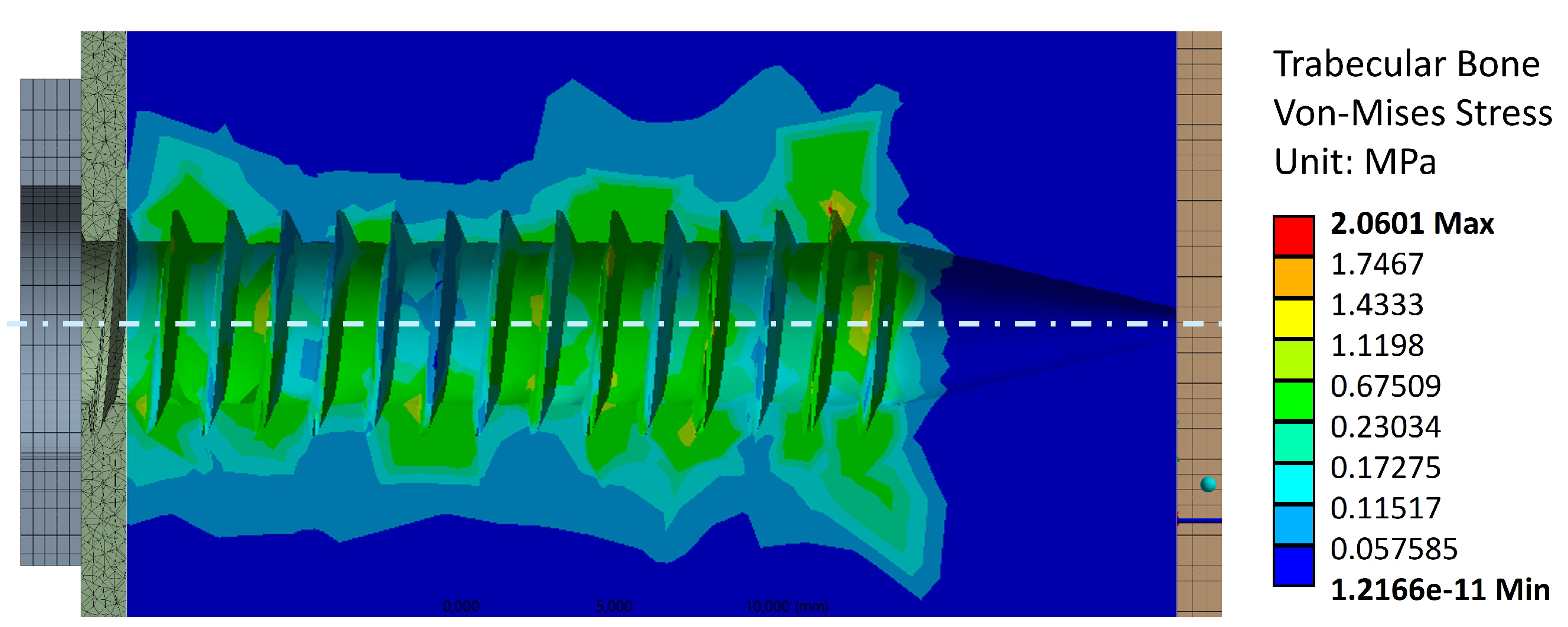
Figure 8.
Stress distribution in the external cortical walls due to tightening torque.
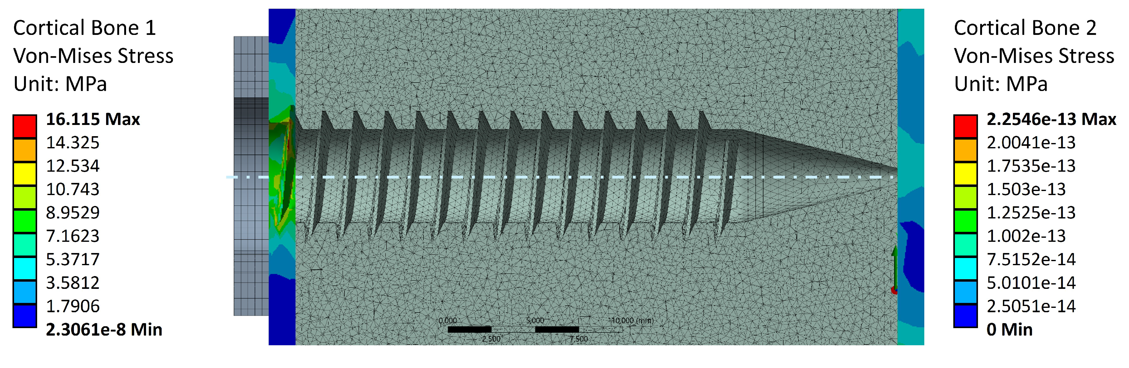
Figure 9.
Stress distribution throughout the model.
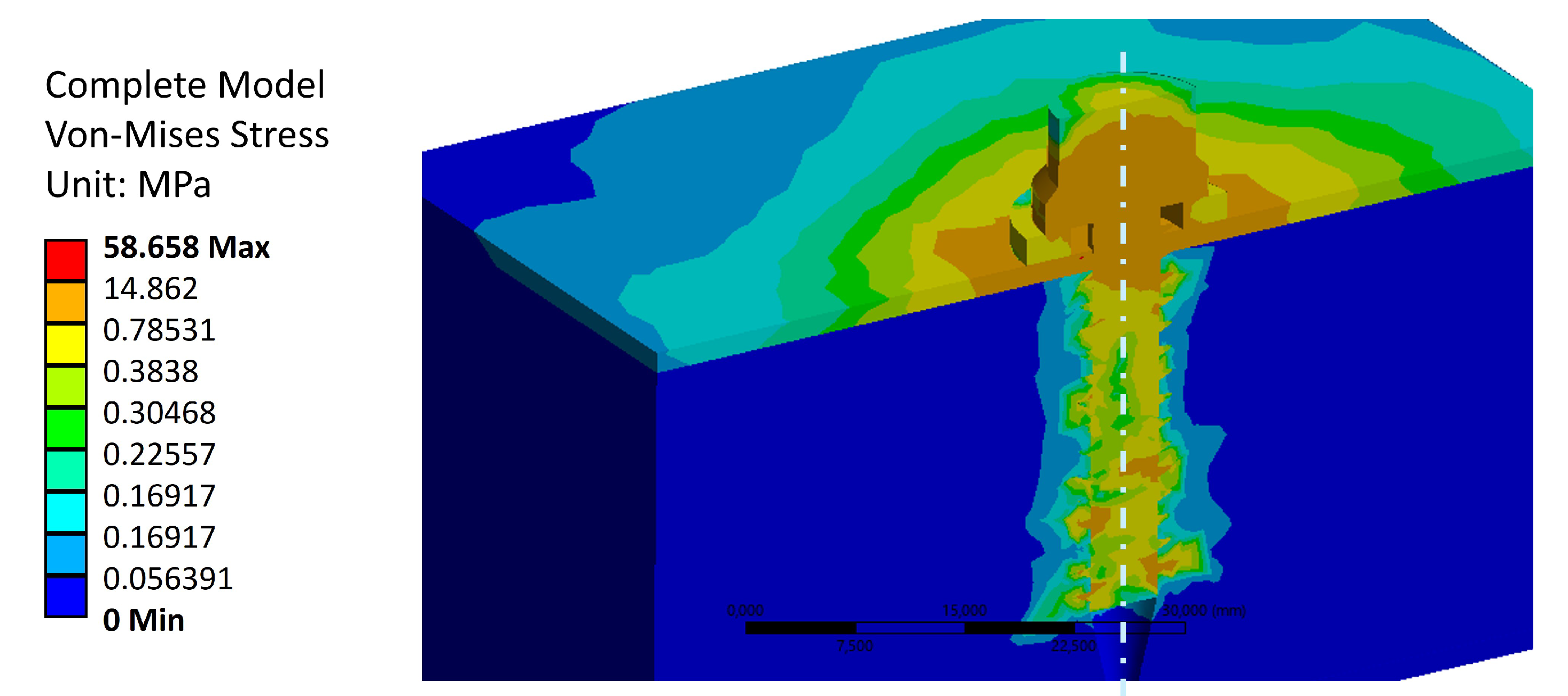
Figure 10.
Stress distribution in the trabecular bone due to the effect of a tightening torque and an extraction load. The purple areas indicate regions where the trabecular bone stress becomes greater than 5 [MPa], indicating failure.
Figure 10.
Stress distribution in the trabecular bone due to the effect of a tightening torque and an extraction load. The purple areas indicate regions where the trabecular bone stress becomes greater than 5 [MPa], indicating failure.
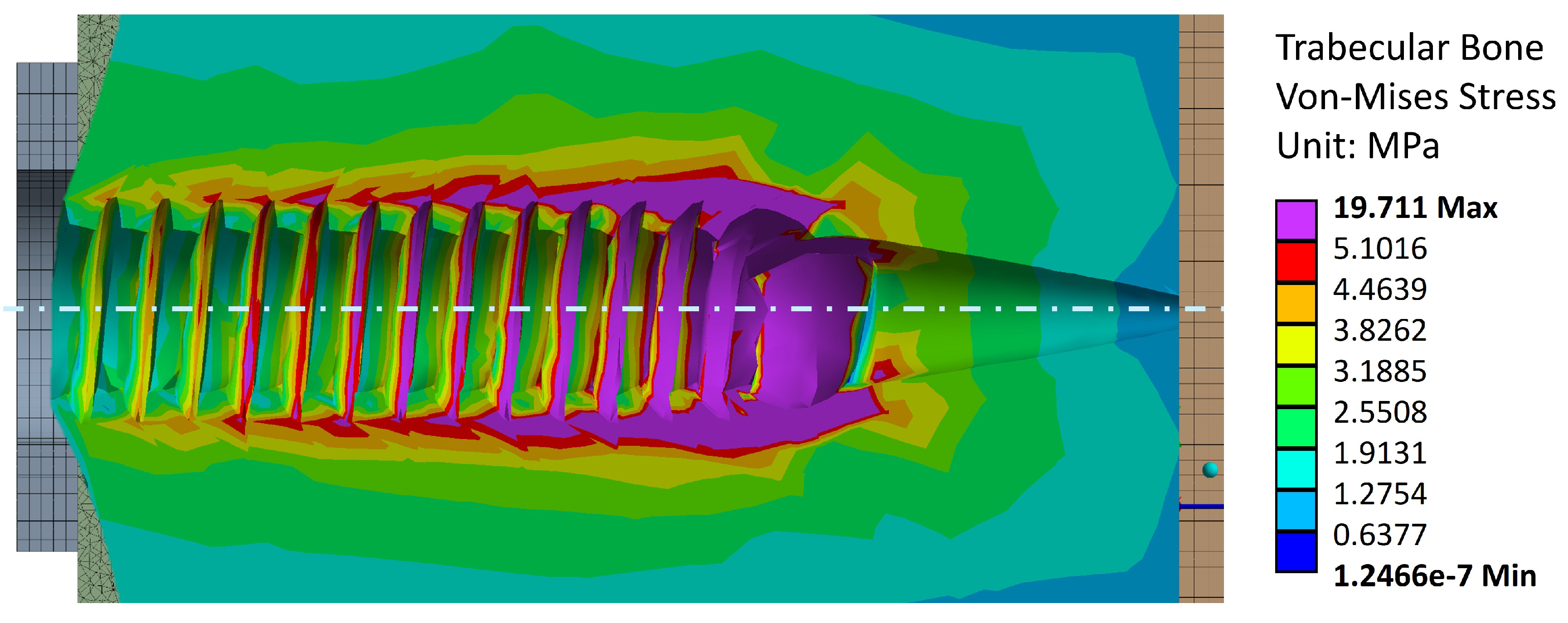
Figure 11.
Displacement distribution in the trabecular bone due to effect of a tightening torque and an extraction load.
Figure 11.
Displacement distribution in the trabecular bone due to effect of a tightening torque and an extraction load.
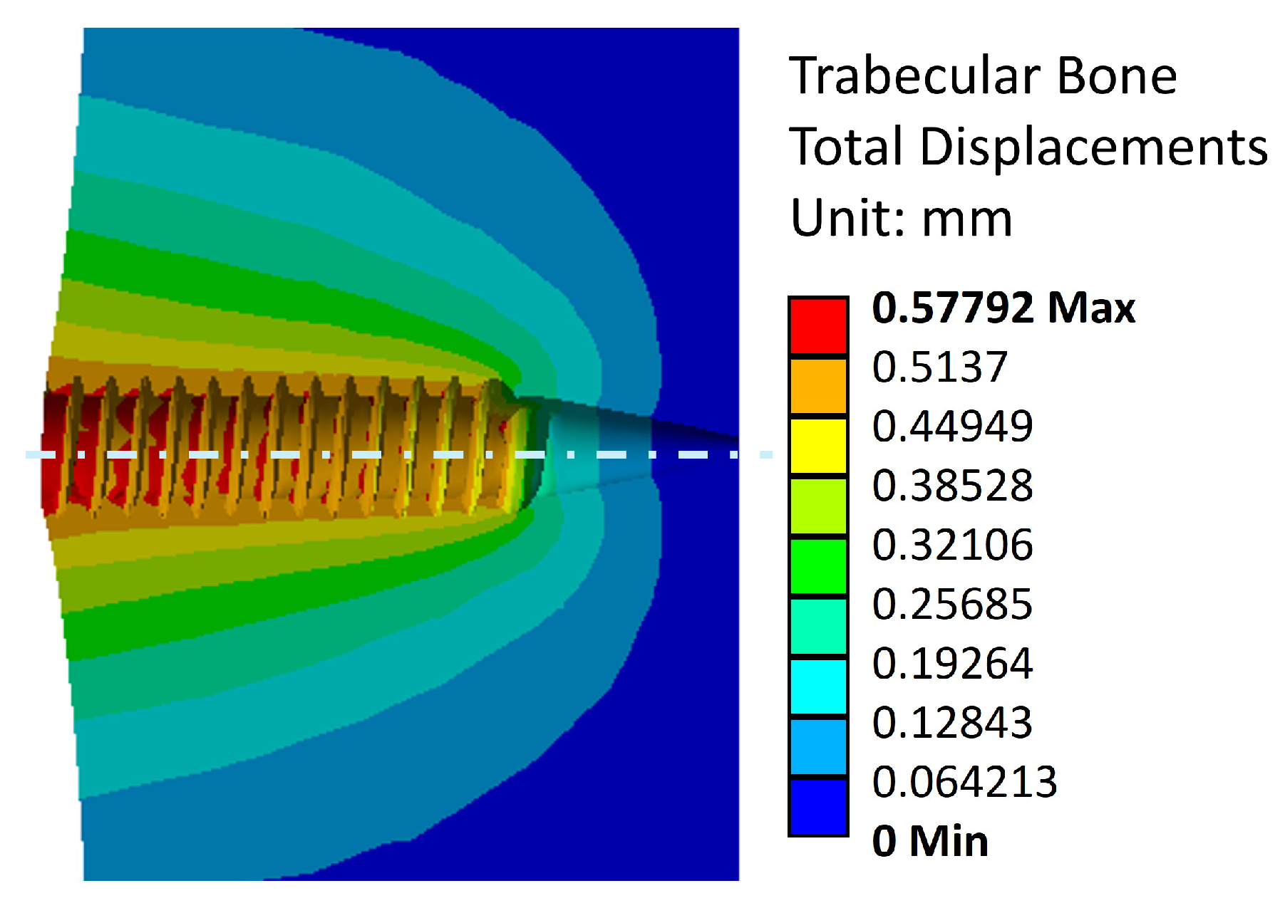
Figure 12.
Displacement distribution across the model.
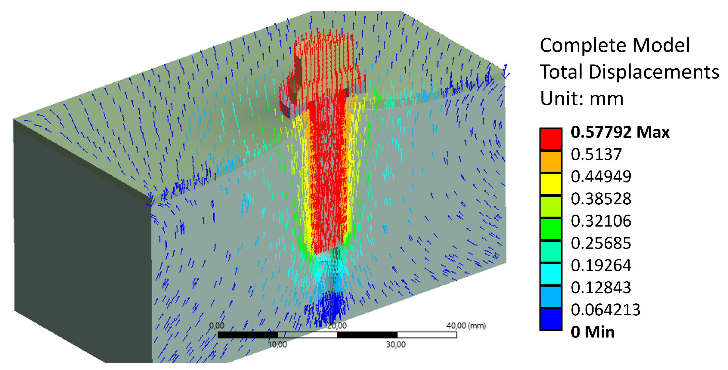
Figure 13.
Stress distribution in the cortical bones due to tightening torque and an extraction load.
Figure 13.
Stress distribution in the cortical bones due to tightening torque and an extraction load.
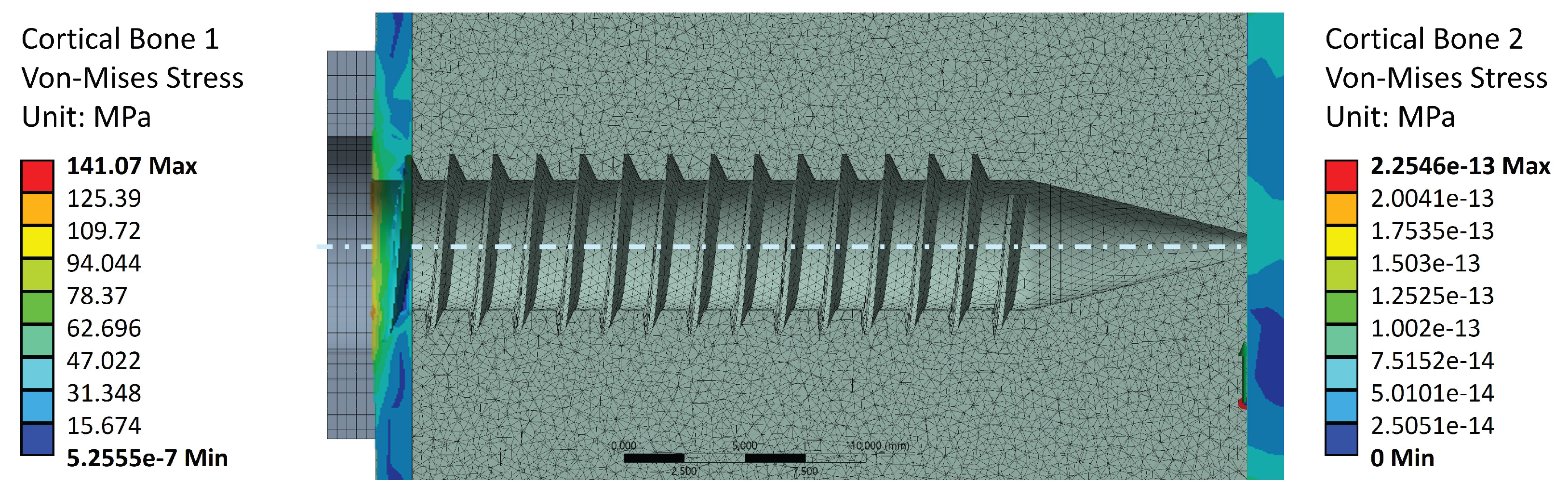

Table 1.
Model elements’ mechanical properties.
| Structures | Mechanical | Young’s | Poisson | References |
|---|---|---|---|---|
| strength [MPa] | Modulus [MPa] | ratio | ||
| Porcine Cortical Bone | 80 – 120 | 13500 | 0.3 | [9,31,32,33] |
| Porcine Trabecular Bone | 5 – 15 | 200 | 0.2 | [25,27,32,33] |
| Washer(Structural steel - A36) | 400 – 450 | 210000 | 0.3 | [8] |
| Surgical Screw(Ti-6Al-4V) | 895 | 107000 | 0.3 | [8] |
Table 2.
Elements mesh properties.
| Structure | Size [mm] | Number of nodes | Number of elements |
|---|---|---|---|
| Cortical Bone | 0.5 | 82650 | 55474 |
| Trabecular Bone | 0.1 | 83858 | 77985 |
| Surgical Screw | 0.3 | 78556 | 49481 |
| Round Washer | 0.1 | 79758 | 38958 |
Disclaimer/Publisher’s Note: The statements, opinions and data contained in all publications are solely those of the individual author(s) and contributor(s) and not of MDPI and/or the editor(s). MDPI and/or the editor(s) disclaim responsibility for any injury to people or property resulting from any ideas, methods, instructions or products referred to in the content. |
© 2025 by the authors. Licensee MDPI, Basel, Switzerland. This article is an open access article distributed under the terms and conditions of the Creative Commons Attribution (CC BY) license (http://creativecommons.org/licenses/by/4.0/).
Copyright: This open access article is published under a Creative Commons CC BY 4.0 license, which permit the free download, distribution, and reuse, provided that the author and preprint are cited in any reuse.


