

Submitted:
01 July 2024
Posted:
02 July 2024
You are already at the latest version
Abstract
Topological interlocking assembly (TIA) and computational architecture treat form as an emergent property of a material system, where the final shape results from the interplay of geometries and geometric interdependencies influenced by material, structural, and fabrication constraints. This paper posits that TIA is an ideal pedagogical tool for introducing students to computational architecture, its theoretical foundations and design principles. Specifically, defining TIA as a material system provides a robust educational approach for engaging students with computation, fostering design processes through bottom-up, hands-on investigations and procedural logic, understanding generative geometric rules, and exploring the flexibility of parametric variations. The methodology is illustrated through a Design Workshop and study unit from the Bachelor’s and Master’s programs at the Faculty for the Built Environment, University of Malta. The paper presents four investigations of defining a material system based on TIA - of tetrahedra, cones, octahedra, and osteomorphic blocks—as case studies to demonstrate how these exercises introduce students to computational thinking, parametric design, and fabrication techniques. Finally, the paper discusses the advantages and limitations of this pedagogical methodology.
Keywords:
topological interlocking assembly
; computational architecture
; architectural education
; material system
1. Introduction
The notion of topological interlocking assembly (TIA) was introduced by Yuri Estrin and Arcady Dyskin in material science 2001. A TIA is defined by an identical configuration of its constituent elements, their mutual arrangement, and a boundary constraint that holds the whole assembly together [1] (Figure 1a). Elements’ configuration necessitates the alternating rotation of their contact faces to generate the interlocking principle (Figure 1b). In this way, the arrangement of elements in TIA imposes local kinematic constraints, uniquely keeping each element locked in its position solely by the geometrical constraints of its adjacent elements. This distinctive feature, except for the elements at the assembly’s periphery, prevents the removal of each element by either upward, downward, sideways, or rotational displacement by its neighbors [1]. In short, a TIA works as a system of geometries and geometric interdependencies from which the assembly’s form emerges.
In the same way, computational architecture approaches form as an emergent outcome of a system. Its design processes abandon the traditional, Modernist linear approach where the form and its aesthetic dictate structure and material choices. Instead, computational design processes synthesize the form from spatial, structural, and material principles [2]. Thus, the focus is not on the manifest form, that which appears, but on the material system from which the form emerges. The material system is an interaction between internal rules that embed the form and external morphogenetic pressures activated by contextual feedback [3].
From the theoretical perspective of computational architecture, a TIA is a typical example of a material system. For this reason, the paper argues that the TIA is an ideal pedagogical tool for introducing students to computational architecture, its theoretical notions, and design principles.
2. Fundamentals of Computational Architecture
Computational architecture approaches design problems through systemic thinking and derives solutions, or a range of solutions, through bottom-up design processes. Systemic thinking is a holistic examination of broadly applicable interaction patterns that underlay, drive and govern a system. Contrary to reductionist thinking, where a whole is divided into parts, systemic bottom-up thinking recognizes the overall global arrangement of parts as a cohesive, synergetic distribution of their dependences. The system’s behavior is expressed through emergent generative processes.
Computation focuses on problem formulation and process expression, from which a solution or a range of solutions is derived. Computation can both describe a process through the inner principles of its activity and plug-in into the process’s activity, its unfolding [5].
The computational design process seeks to define a system of generative rules, a material system from which it derives solutions. The material system consists of internal rules and external adaptation. The internal rules are based on the relationships between the material system’s constituent elements, while external adaptation is based on contextual feedback. The derived, manifest form is a relative actualization of the material system’s relationships [6].
An algorithm can describe the material system’s internal rules that comprise embedded forms [4]. Computation formulates a material system’s algorithm. Firstly, its bottom-up processes discretize constraints through their underlying mathematic, geometric, syntactic, and formal logic [3]. Next, its procedural logic externalizes these constraints and their interdependencies as generative rules.
3. TIA in Architectural Education
A TIA is more complex than it appears. Students are usually confident that they understand its principles through observation and visual comprehension. However, when asked to 3D model a TIA, its geometries and geometric interdependencies become challenging.
Understanding a TIA requires systemic thinking, and its description requires a procedural synthesis of its spatial, structural, and material principles as internal rules and external adaptations. In conclusion, a TIA can be adequately formulated and apprised if approached as a material system.
For this reason, defining a TIA as a material system is an impactful academic exercise. It offers a valid pedagogical approach in architectural education for students to engage in computation, develop design processes through bottom-up, hands-on investigations and procedural logic, understand generative geometric rules, and explore the versatility of parametric variations.
The paper explains the premise with four case studies from Bachelor’s and Master’s programs at the Faculty for the Built Environment, University of Malta. Three studies showcase how a Year 2 BSc Design Workshop introduces students to computational thinking and parametric design, while the fourth showcases how AUD5641 Architectural Technology 2, a Year 2 MArch study unit, introduces computational design and fabrication.
4. Computational Design Workshop
The Computational Design Workshop was an elective 3 ECTS, seven-week (half-semester) design workshop in Year 2 of the BSc (Built Environment Studies) program between 2013 and 2016. The author was the coordinator and tutor, while the co-tutors over the years included Jing Yao Xu and Kane Borg.
4.1. Design Workshop Task and Methodology
The design workshop task asked students to analyze a specific TIA typology, define it as a material system, and then investigate its potential for adaptation and transformation. Its development was group work, which allowed students with varied skills and interests to take ownership of the aspect of the project that aligned with their affinities.
The essence of the design workshop methodology consisted of two iterative steps, each informing the other: understanding and discretizing TIA’s internal rules and formulating them into an algorithm. With each iteration, students gained knowledge that directly informed their design decisions, further explorations, and evaluations.
In the first step, students used physical scale models to expand their understanding of the geometries of individual elements, the overall assembly, and their interdependencies (Figure 2). Here, the TIA was approached as a spatial arrangement that concurrently subdivided a whole into parts and propagated parts to generate a whole. Students, thus, had to concurrently understand and define geometric rules that govern the relationship between individual elements and the procedural rationality of the assembly as a whole.
In the second step, students expressed the geometric rules formulated in the previous step as an algorithm and ran it several times to validate it. Students could run the algorithm through analogue or digital means, but the priority was to develop it as a digital parametric model of associative geometry1. Each algorithm run entailed systematic variations of inputs, primarily of the surface curvature (planar, single curvature, double curvature) (Figure 3), the angle of the contact face rotation, and trimming planes’ positions. Students rigorously recorded the resulting outputs through cataloguing, which allowed them to assess the emergent forms and investigate the material system’s versatility and limitations.
Finally, as the concluding step of a design workshop, students were prompted to envision the material system’s architectural potential. Proposals were required to leverage the material system’s inherent adaptability and transformative qualities beyond TIA’s original design intentions and construction decisions. Design proposals had to explore TIA’s geometric interactions and interwoven aesthetics rather than the practicalities of constructability and structural plausibility. In short, they were architectural speculations, not realistic applications (Figure 4).
4.2. Design Workshop Outcomes and Varied Investigations
Each group’s understanding of the investigated TIA and formulation of its geometric rules was unique. Consequently, the resultant algorithms differed, leading to diverse formal outcomes, variations, and limitations. The resultant manifest forms appeared different yet similar as they emerged from material systems based on the same generative rule: the TIA interlocking principle.
The divergence among projects was acceptable and encouraged, as the design workshop aimed to foster individual interpretations and explorations rather than pursue a single correct solution. The goal was not for students to develop a material system that actualizes all given inputs. Instead, the workshop sought to cultivate a deep understanding of the material system’s internal rules. Students were expected to fully grasp the range of inputs the material system can actualize and evaluate the capabilities of these outcomes.
4.3. Case Study 01: TIA of Tetrahedra
The TIA of tetrahedra investigation was particularly interesting due to its historical precedent, the Abeille flat vault, which predated the notions of a TIA, computational architecture, and a material system for several centuries.
Joseph Abeille patented the flat vault in 1699 to provide a stone ceiling for the lower storey and pavement for the upper storey with identical voussoirs [7] (Figure 5a). The unique voussoir geometry and the rotation of neighboring voussoirs by ninety degrees allow for a simple method of their mutual arrangement. Each voussoir is carried by two neighboring ones through its protruding cuts while supporting two others on its sloped cuts [7]. The Abeille flat vault is a TIA of regular tetrahedra planarly truncated at their centre and some distance below it (Figure 5b). Throughout history, the Abeille Vault has rarely been used due to the high amount of horizontal thrust that required the demanding construction of boundary constraints, like buttresses or massive walls [8].
Students’ investigations developed four distinct procedural logics to formulate a material system, leading to unique outcomes, limitations, and diverse architectural applications.
The first procedural logic derived the tetrahedron from the diagonals of a cube’s top and bottom faces and generated the assembly as an array of tetrahedra (Figure 6). Thus, the procedural logic solely dealt with the assembly as the propagation of parts to create the whole and omitted to address the assembly as a whole subdivided into parts. The actualization of the resultant material system was limited to a planar surface and regular square gird.
The second procedural logic derived the tetrahedron from a rectangular grid, its chequered pattern, and rotated lines. The chequered pattern defined two tetrahedra types, A and B. Around the mid-point of each side of every rectangle, a line was rotated from the horizontal position. In the case of type A tetrahedra, the lines on the opposite sides of the rectangle were rotated for the angle α in one direction and –α in the other. In the case of type B tetrahedra, it was the reverse (Figure 7).
The second procedural logic and its algorithm were derived and validated through hands-on investigations using physical working models at different scales.
Finally, students developed several design project proposals that speculate the architectural applications of the material system based on the TIA of tetrahedra (Figure 8).
The third procedural logic defined the tetrahedron based on a planar curve c, approximated with equal linear segments, lines a. Each line a is rotated in the curve plane around its end and start points for angle α and –α, respectively. The intersection of the rotated lines, line a’ and line a’’, is Point A. Adjacent Point As define lines b. Line a was also rotated by 90° around its mid-point in the plane normal to the plane of curve c. The rotated line, line a’’’, was translated to line a start and end points as lines c. Line c was also translated to point A as lines d. Lines a and d make tetrahedron type A (green), and lines b and c make tetrahedron type B (violet) (Figure 9).
The resulting material system from the second and third procedural logic retained the TIA principle if their input surfaces were planar or single-curvature surfaces but not if they were double-curvature surfaces.
The fourth procedural logic explored a particular investigation: variations and limitations of the Abeille TIA principle on a geodesic dome (Figure 10).
The physical working model allowed students to both understand the construction sequence and validate the procedural logic (Figure 11).
Finally, albeit very conceptual, proposals for the possible the architectural applications were developed too (Figure 13).
4.4. Case Study 02: TIA of Intersecting Cones
The TIA of intersecting cones investigation also included a historical precedent, the Truchet flat vault. The Truchet flat vault was developed in 1704 to improve the Abeille Vault (Figure 13a). Truchet voussoirs actualized the alternating contact faces rotation of the Abeille voussoirs as undulations of concave and convex double-curved surfaces. Thus, the Truchet voussoir configuration was challenging to fabricate until the introduction of contemporary six-axis CAD/CAM tools [10].
For the same reason, the design workshop task asked students to translate the concave and convex surfaces into single-curvature surfaces and derive them from the intersection of cones. Students’ interpretation of the underlying geometric logic of the TIA of intersecting cones resulted in two procedural logics for a material system (Figure 13b).
The first procedural logic started with a grid of intersecting cones of radius r and height H (Figure 14a). The chequered pattern in the grid defines two cone types, A (light green) and B (dark green). The center C of each cone was at the distance r in the x and y directions from its neighbors. In this way, each A cone intersected four adjacent B cones and was tangent to the next set of A cones. The same applied to B cones. Next, each A cone was trimmed by two B cones in the x direction (Figure 14b) and trimmed by two B cones in the y direction (Figure 14c). Finally, a set of trimming planes, as the offset of the original grid, truncated each cone at its mid-height H (Figure 14e) and some distance below it (Figure 14f).
The resulting material system retained the TIA principle for planar or single-curvature input surfaces but not for double-curved ones (Figure 15a). As the final step of their project, students developed design project proposals that speculate the architectural applications of the material system (Figure 15b).
The second procedural logic started with a square grid. Each side of a grid cell was a tangent that defined a circle, the middle of each cone (Figure 16a). In this way, the grid cell sides remained tangents that defined a closed curve even for irregular grid cells (Figure 16b). The rest of the algorithmic sequence followed the first procedural logic: the chequered grid pattern defined cone types A and B; each A cone was trimmed by two B cones in the x direction and trimmed two B cones in the y direction; two planes, grid offsets, truncated the cones at their mid-heights and some distance below it.
Since the geometric rules of this procedural logic allowed the deformation of the cones, the resulting material system retained the TIA principle for all surface curvatures (Figure 17).
4.5. Case Study 03: TIAs of Octahedra
As with the previous two case studies, students’ interpretations of the TIA of octahedra derived distinct procedural logics for a material system. They differed in how they defined the alternating rotation of elements’ six contact faces to achieve the TIA principle.
The first procedural logic defined an octahedron by connecting the vertices of top and bottom faces, two identical, parallel isosceles triangles. The top triangle was offset by distance H from the bottom and rotated by α = 60° around its centroid. This way, the TIA of octahedra was approached as two parallel fields of triangles, TIA’s top and bottom non-contact faces, elements’ extrados and intrados (Figure 18). The resulting material system retained the TIA principle only for planar surfaces but not for single- and double-curved ones.
The second procedural logic was developed to address this limitation. It introduced a column of infill polygons between the columns of the isosceles triangles. The resulting irregular decagons enabled the material system to be actualized on single-curve surfaces. The procedural logic was validated through investigations of variations and physical models (Figure 19).
The third procedural logic started with a hexagonal grid defining a rotated plane field. Each plane was rotated around a grid cell side by the same angle α but in a direction opposite to the rotation of its neighboring planes. The intersection of the six rotated planes generated an octahedron (Figure 20). The resulting material system retained the TIA principle for all surface curvatures.
5. Computational Design and Fabrication Study Unit
AUD5641 Architectural Technology 2 is a 5 ECTS computational design and fabrication study that is part of the Masters in Architecture (Architectural Design). The study unit coordinators are the author and Steve DeMicoli.
The study unit task and methodology are identical to the BSc Digital Design Workshop but of a broader scope. Students need to develop and investigate variations of a material system derived from an overlay of capacities and constraints of multiple aspects: assembly geometry, material properties, and fabrication limitations. A material system is, thus, developed by recognizing and exploring underlying geometries and geometric interdependencies of the individual elements and their overall assembly, but also the versatility and limitations of the given material, fabrication tools, students’ instrumental knowledge, and construction process requirements [11].
5.1. Case Study 04: TIA of Osteomorphic Blocks
The limited funds in the academic year 2017/2018 focused the study unit investigations on affordable materials and fabrication. The materials available were sheet materials like paper, cardboard, and plastic, as well as any material that fit within the study unit’s limited budget. The available fabrication tool was a laser cutter. The assembly geometry investigated was a TIA of osteomorphic blocks.
The osteomorphic block was invented for wall and column construction in high seismic zones [10]. Similarly to Truchet voussoir, it actualises the interlocking principle as multiple alternations of concave and convex surfaces on the voussoir’s horizontal contact faces. Their fabrication, thus, requires six-axis CAD/CAM tools. The running bond construction sequence enables the TIA principle. Its vertical contact faces are planar (Figure 21a).
Students used iterative prototyping at multiple scales and with different materials to investigate how the constraints of the TIA principle, fabrication tools, and material properties mutually inform each other. More precisely, through tail-and-error, hands-on investigations, students gained knowledge that directly informed their design decisions, such as choosing materials and fabrication techniques, further explorations, and architectural applications.
Since the fabrication of the concavo-convex surfaces required six-axis milling, the investigations of TIA geometries and geometric interdependencies had to be rethought from the start within the constraints of the laser’s two-axis cutting abilities and sheet material properties. As a result, elements’ concavo-convex surfaces became planar surfaces rotated in alternating directions. The translation necessitated the formulation of two element types to retain the assembly’s interlocking principle (Figure 21b).
Students had to develop a fabrication technique that ensured the elements’ rigorous geometric definition and contact face planarity. They used a casting process with plaster of Paris and moulds made from laser-cut, folded sheet materials.
The mould material had to be suitable for laser cutting, stiff enough to retain the mould’s shape during the cast and contact surfaces free of warps, smooth to enable easy moulding, sturdy enough to be reused for multiple casts, and allowing tooling perforations. Tooling perforations had to allow the mould to fold in two directions (peaks and valleys) without impacting the mould’s stiffness or allowing the casting material to leak (Figure 22a). Iterative prototyping also allowed students to understand the fabrication challenges of scaling up the mould using the same material (Figure 22b).
The plaster mix had to be viscous to allow an easy casting process and sharp edges but not seep through the perforations at the folds, create surface wraps, or crack during drying.
Iterative prototyping established an interdependency between the plaster’s viscosity and the faces’ rotation angle, stress concentration at the sharp edges, and the length of the casting and drying processes (Figure 23).
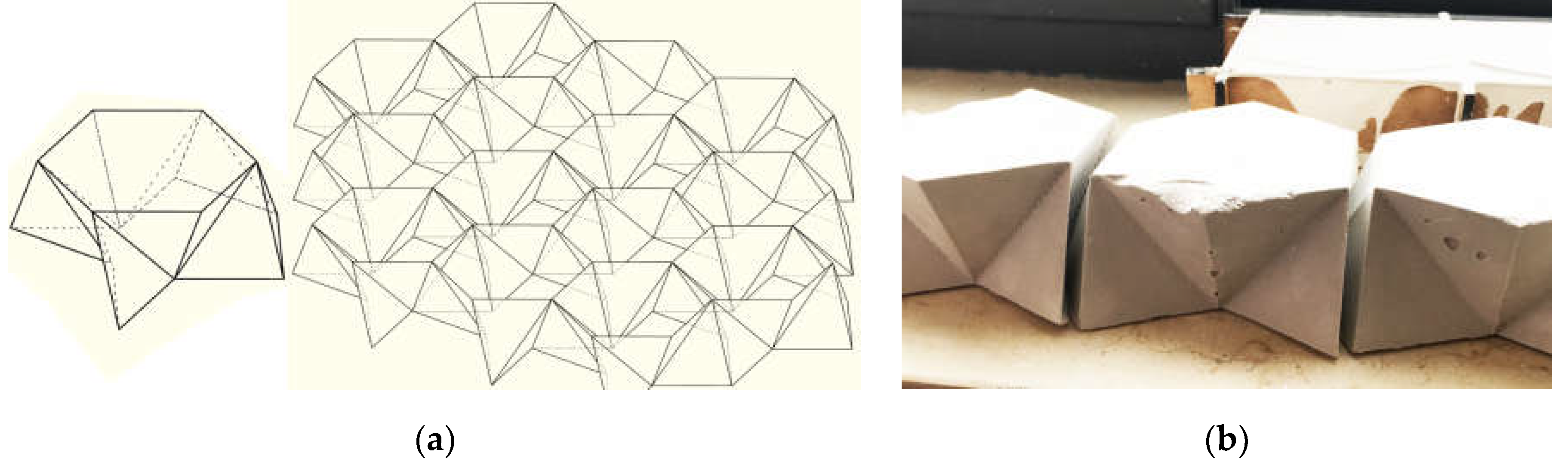
An additional procedural logic investigated a single element type with a configuration of no planar faces to increase its degree of interlocking (Figure 24a). Although theoretically, the configuration achieved a more optimal interlocking, the added complexity reduced the precision of its fabrication. The result was unavoidable warping and imperfections of elements’ contact surfaces that prevented the interlocking, the principle it was trying to optimize (Figure 24b).
In short, prototype-based investigations exposed material properties and fabrication limitations as external adaptations that hindered internal rules from manifesting the embedded, interlocking forms.
6. Limitations
The case studies also revealed certain limitations in using a TIA as a pedagogical tool.
Firstly, students found some TIA typologies easier to comprehend, leading to variations in the depth of investigations and the versatility of derived material systems. For instance, investigations centred around tetrahedra allowed students to engage in more comprehensive investigations, thus gaining broader design knowledge than students who tackled other TIA typologies.
Next, the tutors’ familiarity with TIA geometries and interdependencies influenced their ability to remain impartial in guiding students towards their unique investigations. Unintentionally, tutors imposed their understanding of TIA’s underlying rules, resulting in less diverse student projects over time. Student investigations became more tutor-led, losing the bottom-up approach driven by personal hands-on knowledge gained with each iteration. Consequently, prescription and similarity supplanted ownership, divergence, explorations, and versatility.
Further, TIA is inherently complex in structure, fabrication, and construction. Students explored TIA material systems for various surface curvatures, focusing on descriptive geometry unrelated to buildability and structural stability. Case studies emphasized investigations of typical geometries and interdependencies of TIA’s constituent elements. They did not address necessary boundary constraints for assembly or their impact on edge and corner configurations. Additionally, fabricating and assembling TIA entail significant costs, posing challenges in proposing realistic and feasible architectural applications.
Finally, the design workshop primarily focused on digital parametric modelling to run algorithms, requiring a steep software learning curve to achieve this. Consequently, students spent most of their time acquiring instrumental knowledge of the software to encode algorithms rather than exploring its generative potential. Instrumental knowledge of the software directly influenced the understanding of TIA and the formulation of its algorithm, making the design process subservient to the digital tool’s limitations. The result limited engagement with computational thinking as instrumental software knowledge, or its lack of, directly enabled or disabled students in the act of design [12].
As a result, the design workshop tasks and methodology have evolved in recent years. The focus has shifted towards defining two- and three-dimensional tessellations as material systems. If interlocking is introduced, it is not topological but planar, reminiscent of M.C. Escher’s work. This approach simplifies investigations but allows for more significant student appropriation, ownership, and customizations. Analogue algorithm formulations use pseudocode and flowchart formats. Investigations are conducted primarily hands-on. The inform algorithm formations, output variations, limitations, materiality, fabrication tools and techniques, and on-site assembly sequence.
Students find architectural applicability of tessellations more intuitive, as they can be applied at various scales while addressing multiple aspects such as program requirements, environmental performance, and aesthetics. Students can address structural principles, architectural detailing, and construction processes of simplified notions investigated. Still, although the design workshop’s learning outcomes increased in range, students’ geometric investigations have reduced in depth and spatial understanding.
7. Conclusion
In conclusion, computational architecture recognizes form as an emergent outcome of context. Its design processes integrate context to establish a material system, and the material system, in turn, unfolds the context within its outcomes, shaping the manifest form [11].
The primary learning outcome of the described Design Workshop and Study Unit was to shift students’ approach to the design process from a top-down imposition focused solely on forms’ aesthetics and performance. Instead, the aim was to introduce students to computation-based design processes that involve investigations and explorations, leading to a bottom-up generative formation process capable of addressing and negotiating multiple design constraints. Their emphasis lies in problem formulation and process expression, from which a solution, or range of solutions, emerges.
The case studies discussed demonstrate that introducing students to TIA as a material system through principles of computational design enabled them to explore and engage with the unfamiliar. On a broader theoretical level, students departed from their established design thinking and methods of working to develop design processes that interacted with and responded to the unknown and uncertain.
In short, students derived designs from and for the context they encountered.
References
- Dyskin, A.V.; Estrin, Y.; Kanel-Belov, A.J.; Pasternak, E. Topological interlocking of platonic solids: a way to new materials and structures. Philosophical magazine letters 2003, 83(3), 197–203. [Google Scholar] [CrossRef]
- Oxman, R.; Oxman, R. New structuralism: design, engineering and architectural technologies. Architectural Design 2010, 80(4), 14–23. [Google Scholar] [CrossRef]
- Kwinter, S.; Davidson, C. Far from equilibrium: essays on technology and design culture. ACTA Press; 2008.
- Tessmann, O. Interlocking manifold kinematically constrained multi-material systems. In Advances in Architectural Geometry 2012, 2013 (pp. 269-278). Springer, Vienna.
- Picon, A. Digital fabrication, between disruption and nostalgia. Instabilities and Potentialities: Routledge; 2019. p. 223-238.
- Kotnik, T. (Aalto University) Personal communication, Parametric Architectural Design Workshop at the University of Malta, 2012.
- Fleury, F. Evaluation of the perpendicular flat vault inventor’s intuitions through large scale instrumented testing. In Third International Congress on Construction History, Brandenburg University of Technology Cottbus, Germany, 20th-24th May 2009 2009 (p. 1).
- Brocato, M.; Mondardini, L. A new type of stone dome based on Abeille’s bond. Int J Solids Structures 2012, 49(13), 1786–1801. [Google Scholar] [CrossRef]
- Gallon, J. Machines et inventions approuvées par l’Academie Royale des Sciences depuis son établissement jusqu’à présent; avec leur description. chez Gabriel Martin, Jean-Baptiste Coignard, fils, Hippolyte-Louis Guerin, Ruë S. Jacques; 1777.
- Etlin, R.; Fallacara, G.; Tamborero, L. Plaited Stereotomy, Stone Vaults for the Modern World. Rome: ARACNE editrice S.r.l; 2008.
- Miodragovic Vella, I. Digital design in ‘peripheral’ contexts. Digital Design Reconsidered, 41st eCAADe 2023 (pp. 11-21). eCAADe and Graz University of Technology Faculty of Architecture; Gratz Austria.
- Witt, A.J. A machine epistemology in architecture. encapsulated knowledge and the instrumentation of design. Candide. Journal for architectural knowledge 2010, 3, 37–88. [Google Scholar]
| 1 | Parametric models were developed through visual programming using Grasshopper, the associative
modelling plug-in for Rhinoceros 3D modelling software. In this way, students used CAAD software as a
constructive form generation and evaluation medium, not solely for visualisation. Parametric models also
provided fabrication information for physical scale models and prototyping for the next iteration. They also exposed the constraints of the construction sequence. |
Figure 1.
Topological interlocking assembly (TIA) interlocking principle: (a) elements’ identical configuration and their mutual arrangement; (b) different variations of alternating rotation of elements’ contact faces.
Figure 1.
Topological interlocking assembly (TIA) interlocking principle: (a) elements’ identical configuration and their mutual arrangement; (b) different variations of alternating rotation of elements’ contact faces.
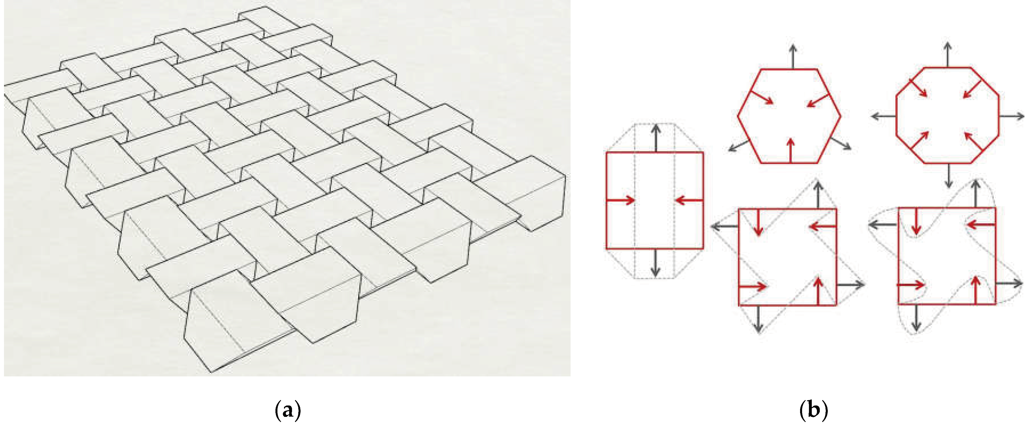
Figure 2.
Student investigations of TIA principles using scale models: (a) TIA of octahedra; (b) TIA of osteomorphic blocks.
Figure 2.
Student investigations of TIA principles using scale models: (a) TIA of octahedra; (b) TIA of osteomorphic blocks.
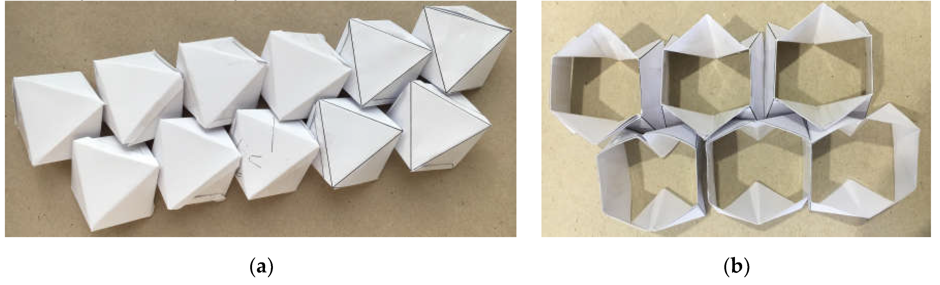
Figure 3.
Catalogue of a material system based on TIA of octahedra showcasing variations of the surface curvature inputs. Diagrams by Reuben Borg and Mauro Debono.
Figure 3.
Catalogue of a material system based on TIA of octahedra showcasing variations of the surface curvature inputs. Diagrams by Reuben Borg and Mauro Debono.
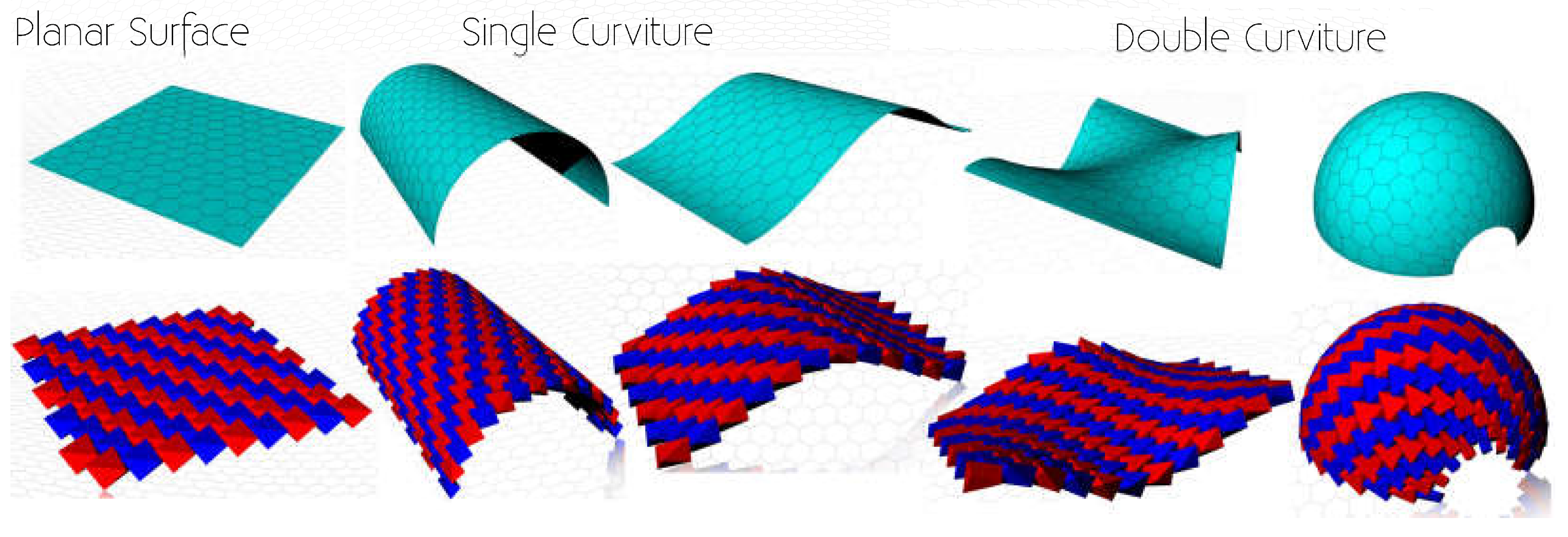
Figure 4.
Architectural speculations of material systems based on: (a) TIA of tetrahedra (Visual by Christopher Azzopardi and Neville Bugeja), (b) TIA of octahedra (Visual by Reuben Borg and Mauro Debono).
Figure 4.
Architectural speculations of material systems based on: (a) TIA of tetrahedra (Visual by Christopher Azzopardi and Neville Bugeja), (b) TIA of octahedra (Visual by Reuben Borg and Mauro Debono).
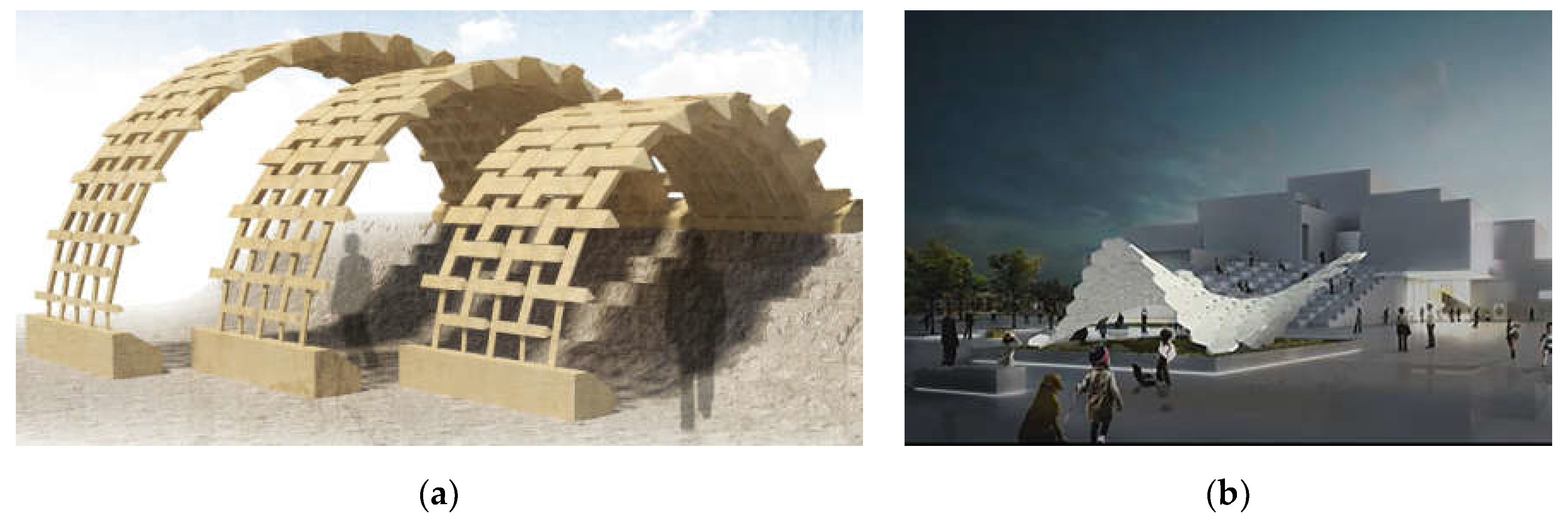
Figure 5.
TIA of tetrahedra: (a) The Abeille Flat Vault patent application in [9]; (b) TIA of regular tetrahedra [2].
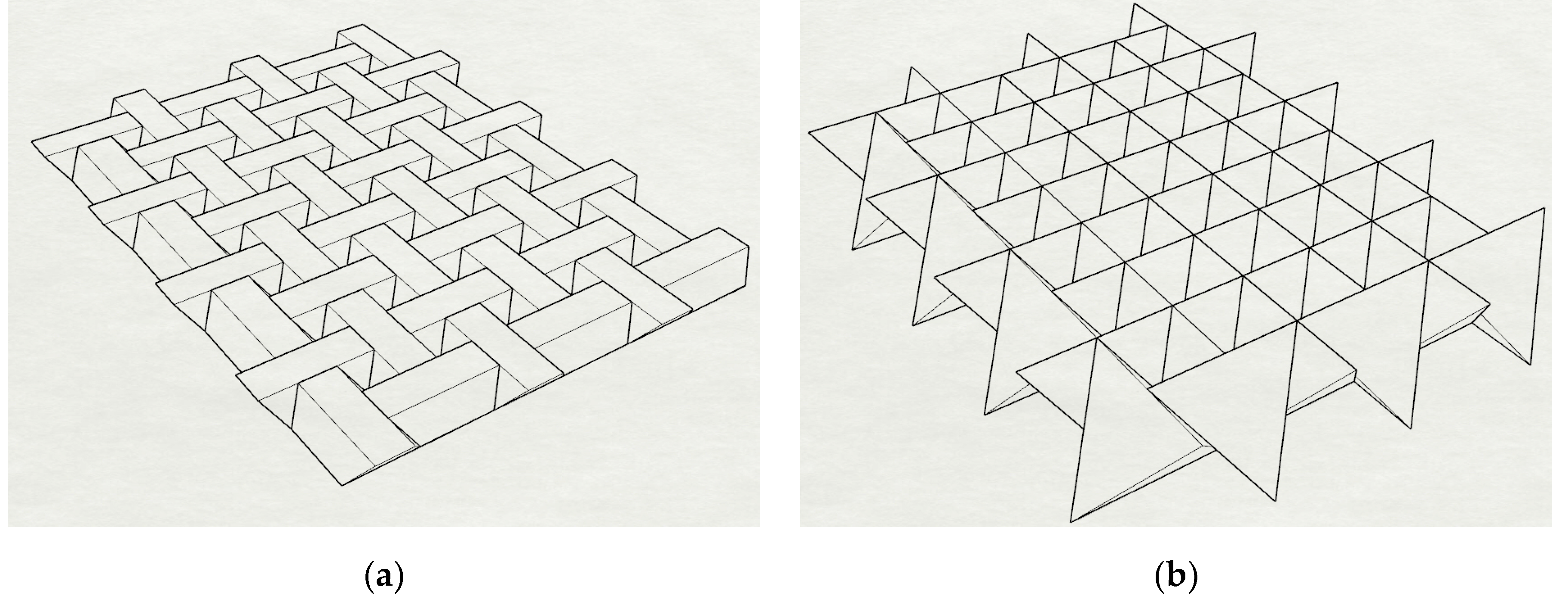
Figure 6.
Tetrahedron definition based on the diagonals of a cube’s top and bottom faces.
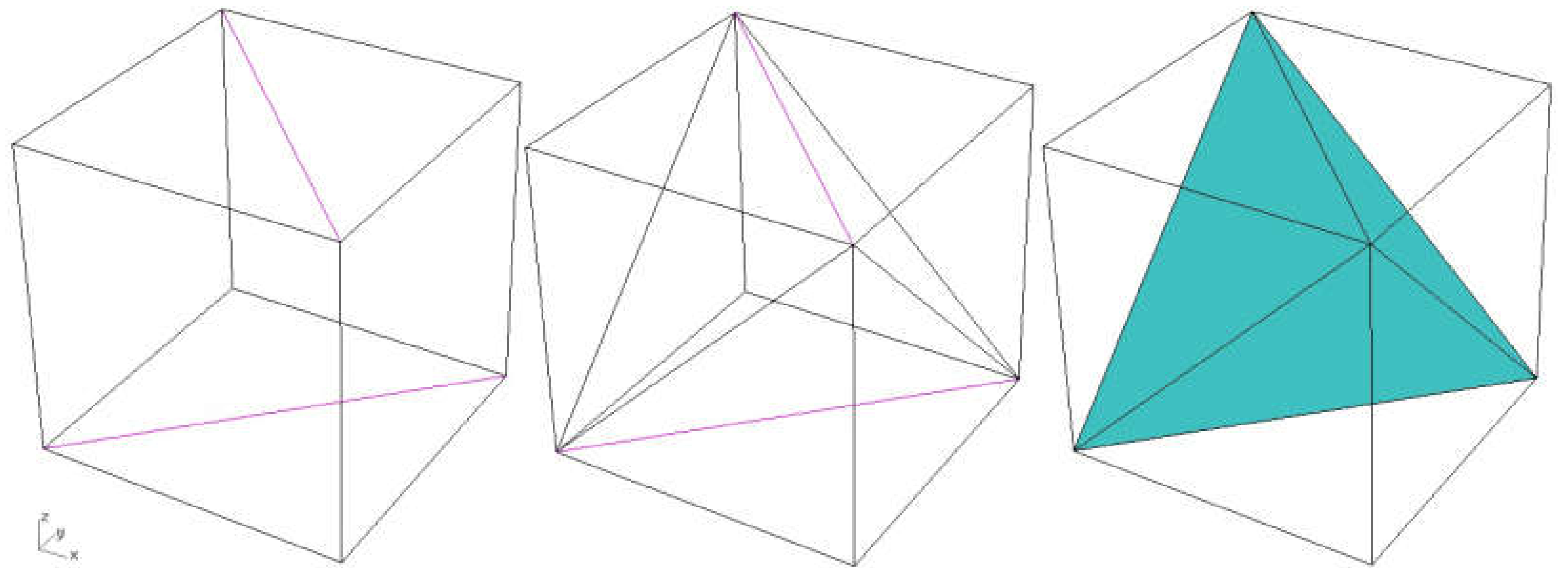
Figure 7.
Diagram of the second procedural logic for the material system based on TIA of tetrahedra.
Figure 7.
Diagram of the second procedural logic for the material system based on TIA of tetrahedra.
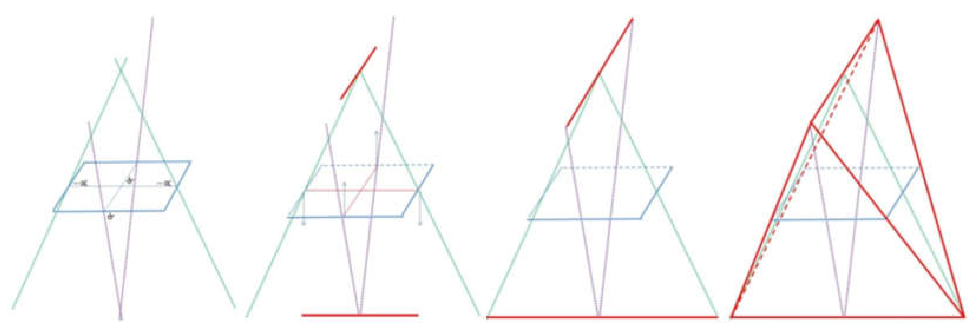
Figure 8.
Architectural speculations of the material system are based on the TIA of tetrahedra (Visuals by Christopher Azzopardi and Neville Bugeja).
Figure 8.
Architectural speculations of the material system are based on the TIA of tetrahedra (Visuals by Christopher Azzopardi and Neville Bugeja).
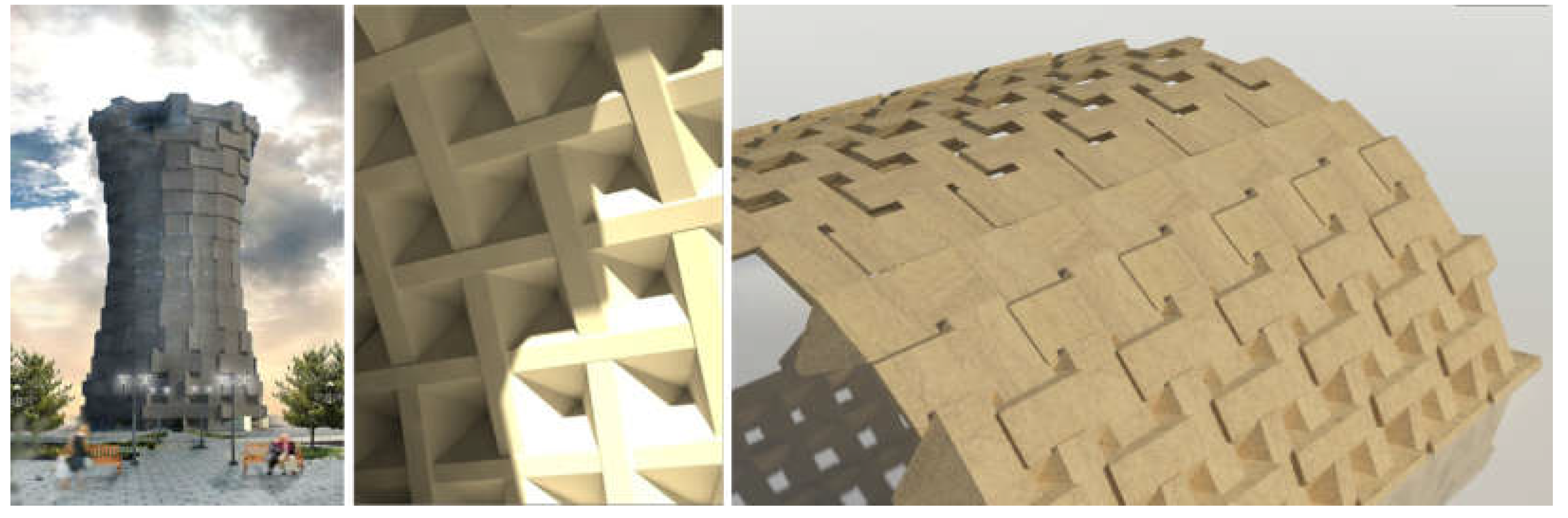
Figure 9.
Diagram of the third procedural logic for the material system based on TIA of tetrahedra.
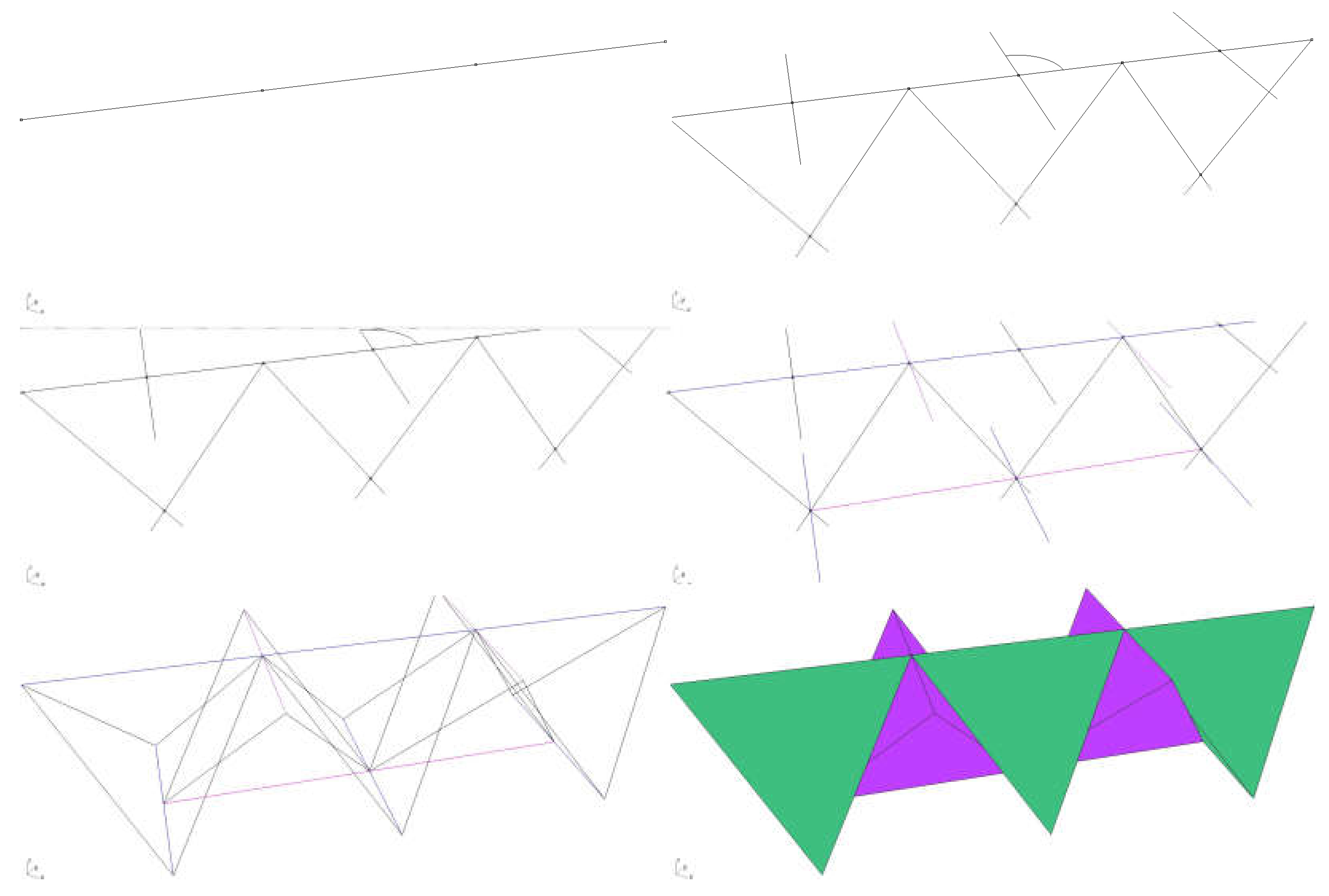
Figure 10.
Parametric variations of the TIA of tetrahedra material system as a geodesic dome (Diagrams by Sacha Cutajar and Kristine Pace).
Figure 10.
Parametric variations of the TIA of tetrahedra material system as a geodesic dome (Diagrams by Sacha Cutajar and Kristine Pace).
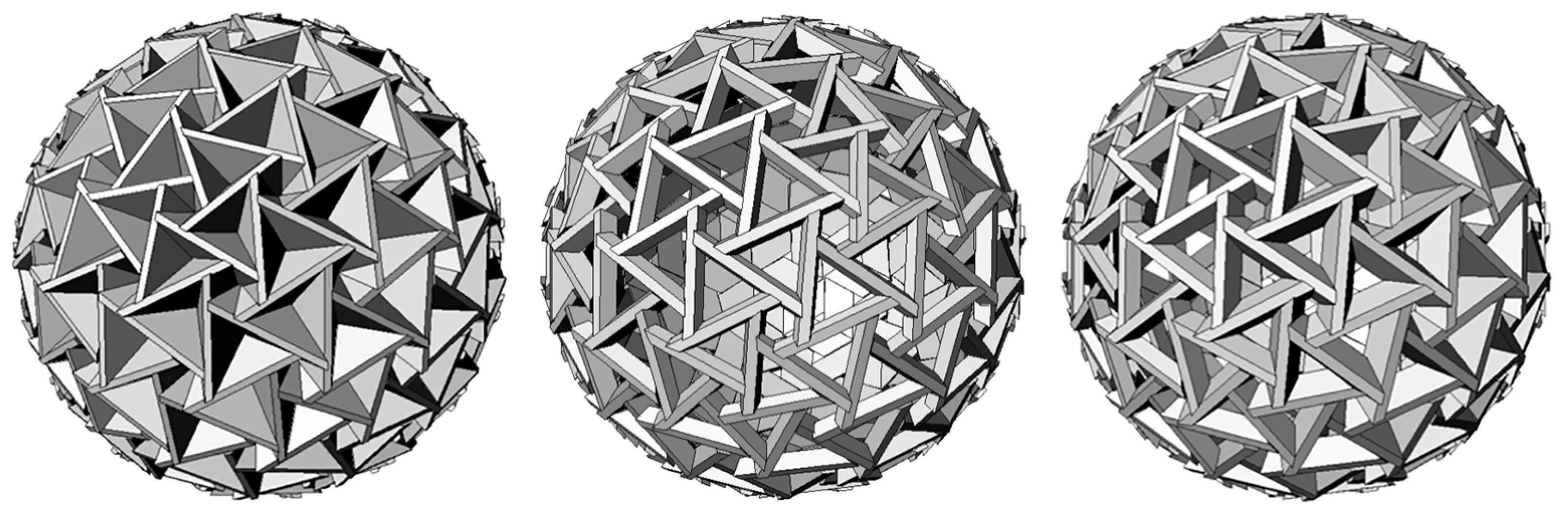
Figure 11.
The physical working model of the TIA of tetrahedra material system as a geodesic dome (Models by Sacha Cutajar and Kristine Pace).
Figure 11.
The physical working model of the TIA of tetrahedra material system as a geodesic dome (Models by Sacha Cutajar and Kristine Pace).
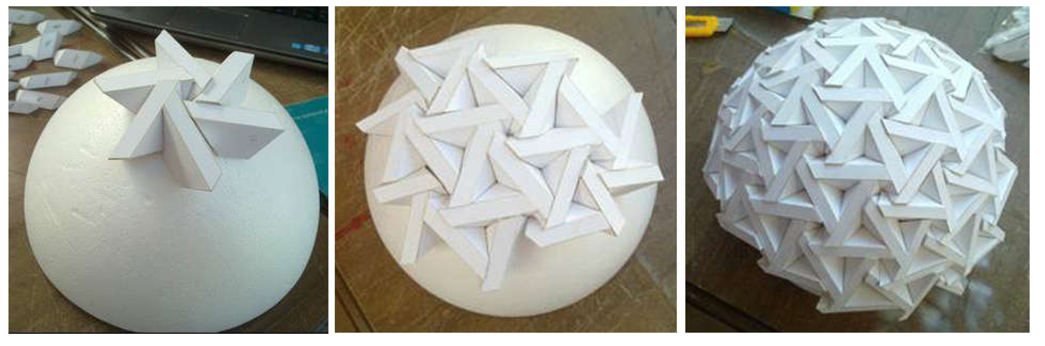
Figure 12.
The conceptual design proposals for TIA of tetrahedra material system as a geodesic dome (Visuals by Sacha Cutajar and Kristine Pace).
Figure 12.
The conceptual design proposals for TIA of tetrahedra material system as a geodesic dome (Visuals by Sacha Cutajar and Kristine Pace).
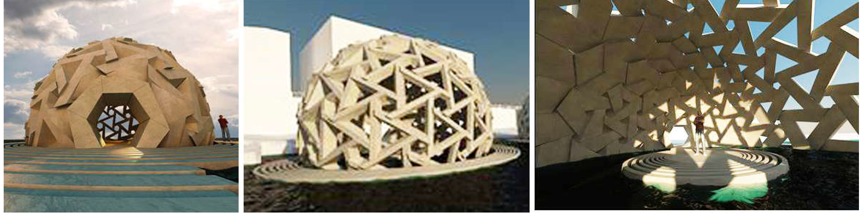
Figure 13.
a) Truchet Flat Vault, top and bottom views; b) TIA of intersecting, truncated top and bottom views.
Figure 13.
a) Truchet Flat Vault, top and bottom views; b) TIA of intersecting, truncated top and bottom views.
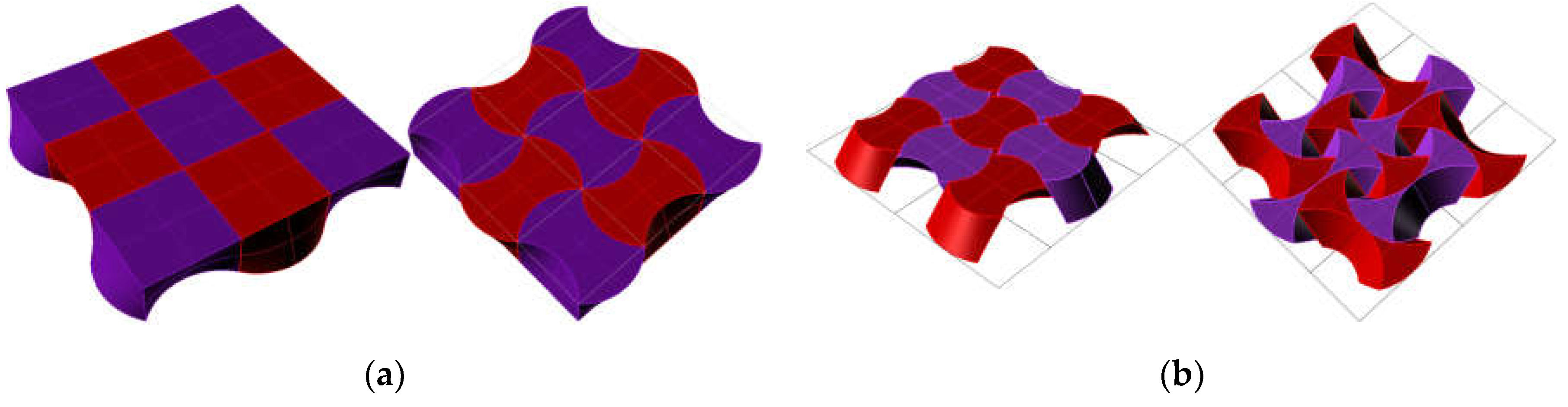
Figure 14.
Diagram of the first procedural logic for the material system based on TIA of intersected, truncated cones.
Figure 14.
Diagram of the first procedural logic for the material system based on TIA of intersected, truncated cones.
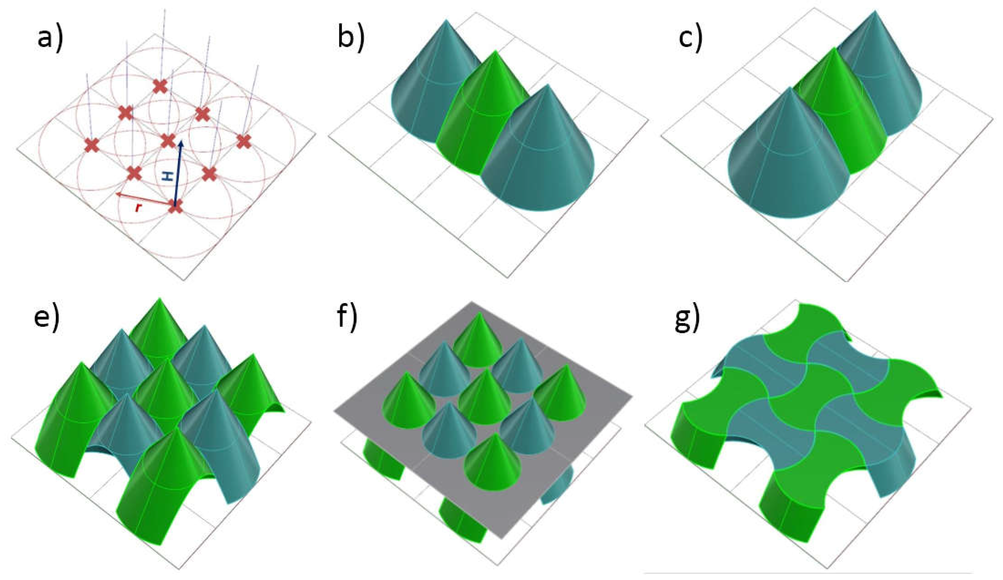
Figure 15.
Material system based on TIA of intersected, truncated cones: a) actualized on a barrel vault (single-curved surface); b) architectural speculations (Visuals by Andrew Pillow, Isaac Bezzina and David Borg).
Figure 15.
Material system based on TIA of intersected, truncated cones: a) actualized on a barrel vault (single-curved surface); b) architectural speculations (Visuals by Andrew Pillow, Isaac Bezzina and David Borg).
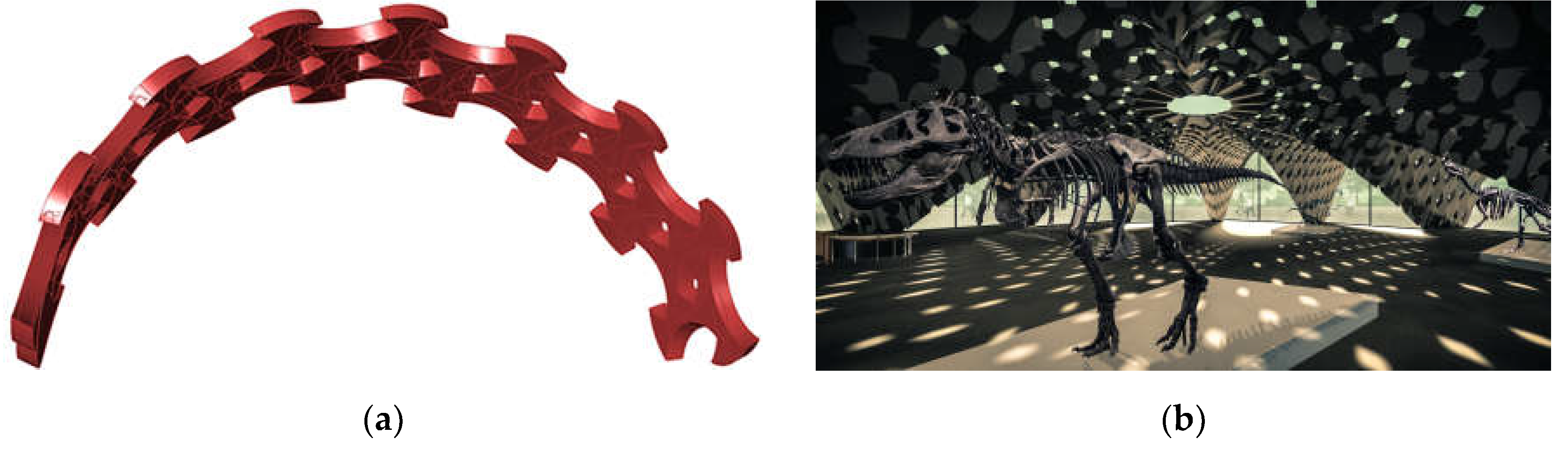
Figure 16.
Second procedural logic for a material system based on TIA of intersecting cones: a) the square grid cell that defines the cone base, regular and irregular polygon; b) on an irregular grid (Visuals by Andrew Pillow, Isaac Bezzina and David Borg).
Figure 16.
Second procedural logic for a material system based on TIA of intersecting cones: a) the square grid cell that defines the cone base, regular and irregular polygon; b) on an irregular grid (Visuals by Andrew Pillow, Isaac Bezzina and David Borg).
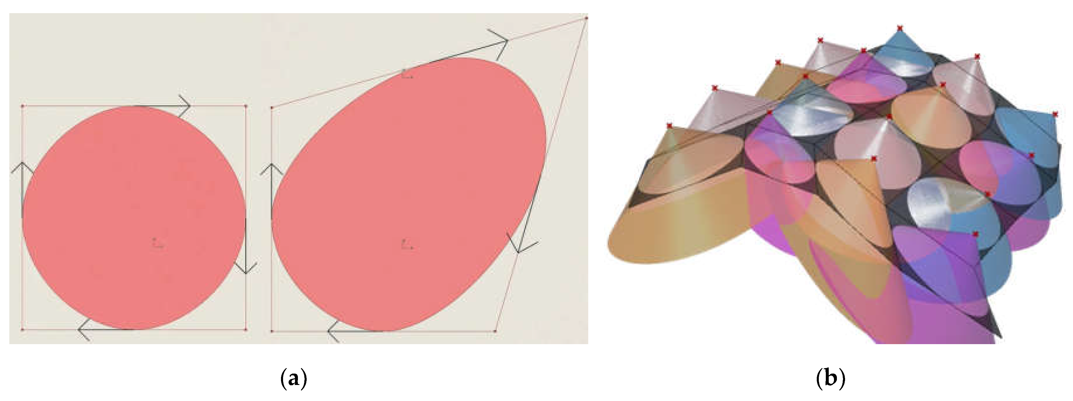
Figure 17.
Second procedural logic for a material system based on TIA of intersecting cones: a) actualized on a planar surface; b) actualized on a double-curved surface (Visuals by Andrew Pillow, Isaac Bezzina and David Borg).
Figure 17.
Second procedural logic for a material system based on TIA of intersecting cones: a) actualized on a planar surface; b) actualized on a double-curved surface (Visuals by Andrew Pillow, Isaac Bezzina and David Borg).
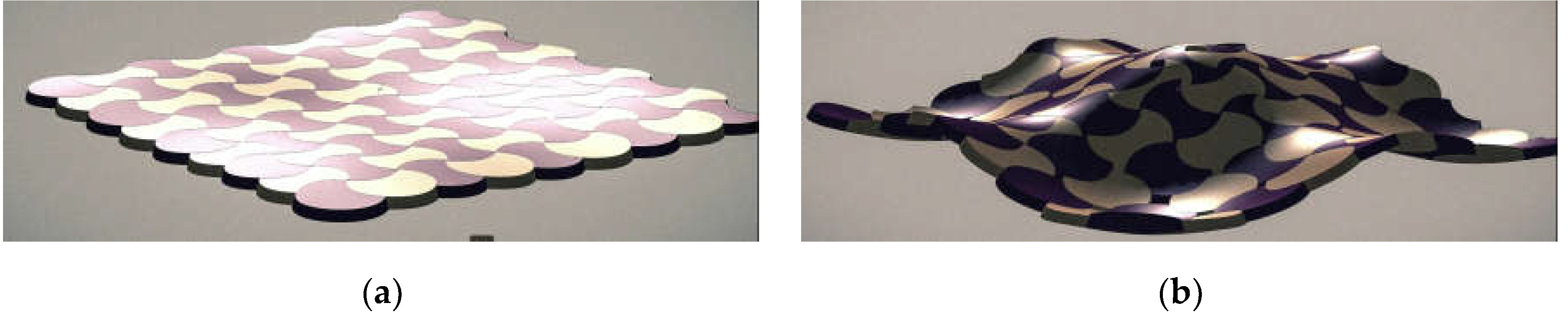
Figure 18.
Diagram of the algorithm of the first procedural logic for a material system based on TIA of octahedra based on two fields of parallel triangles.
Figure 18.
Diagram of the algorithm of the first procedural logic for a material system based on TIA of octahedra based on two fields of parallel triangles.
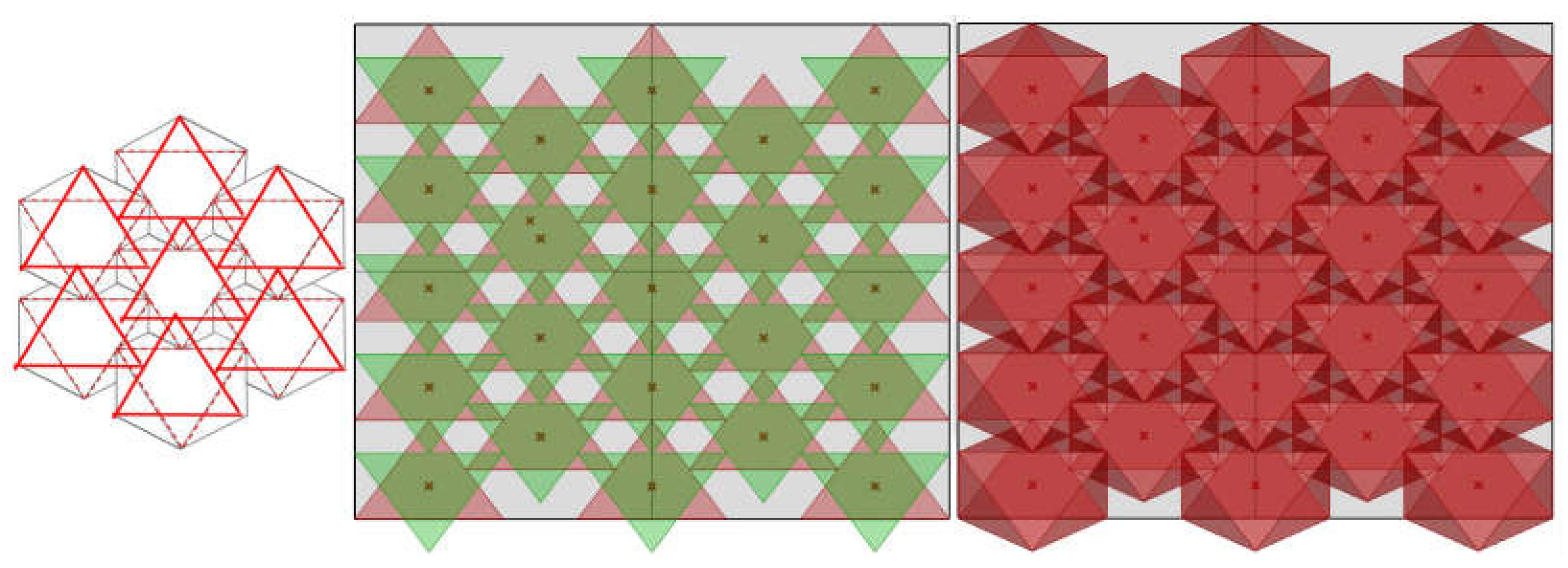
Figure 19.
Diagram of the algorithm of the second procedural logic for a material system based on TIA of octahedra based on infill polygons.
Figure 19.
Diagram of the algorithm of the second procedural logic for a material system based on TIA of octahedra based on infill polygons.
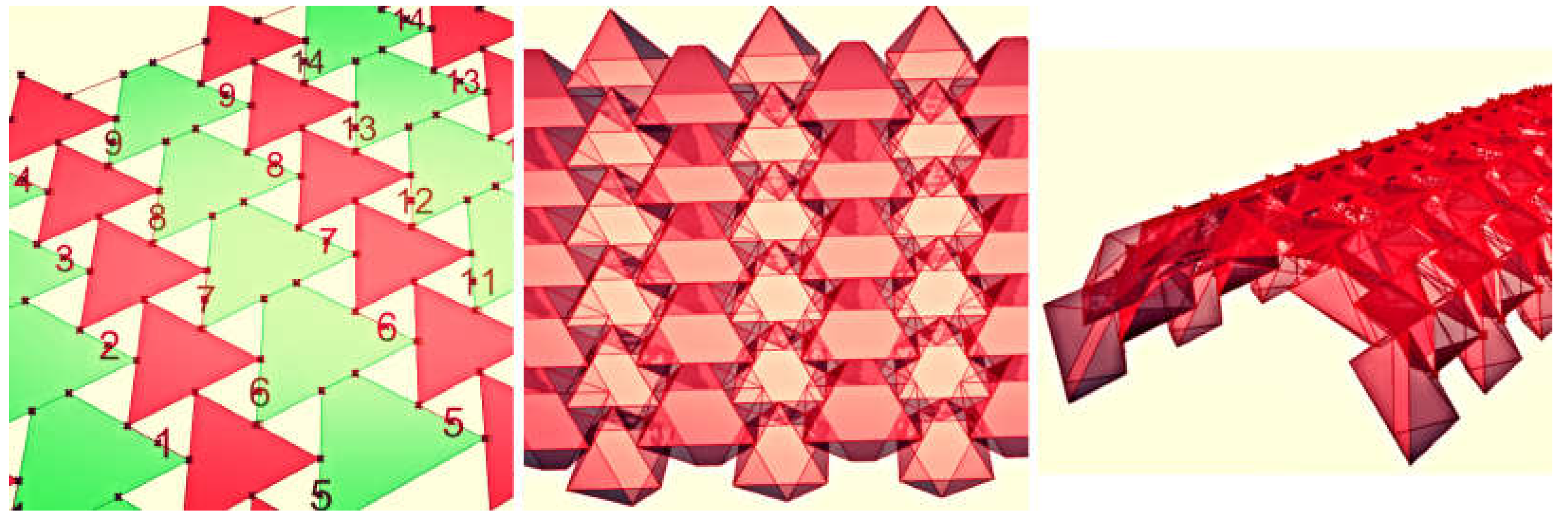
Figure 20.
Diagram of the algorithm of the third procedural logic for a material system based on TIA of octahedra, based on rotated planes. Diagrams by Reuben Borg and Mauro Debono.
Figure 20.
Diagram of the algorithm of the third procedural logic for a material system based on TIA of octahedra, based on rotated planes. Diagrams by Reuben Borg and Mauro Debono.
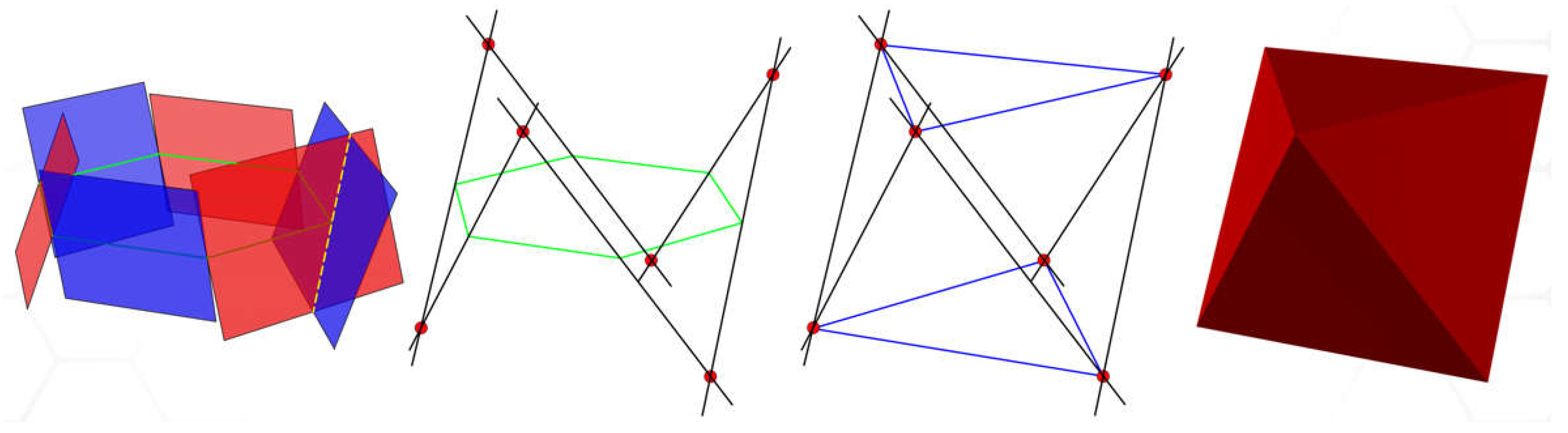
Figure 21.
TIA of Osteomorphic Blocks: (a) an individual block and assembly; (b) TIA of osteomorphic blocks translated into two element types with planar faces (Diagram by Gabriel Barthet).
Figure 21.
TIA of Osteomorphic Blocks: (a) an individual block and assembly; (b) TIA of osteomorphic blocks translated into two element types with planar faces (Diagram by Gabriel Barthet).
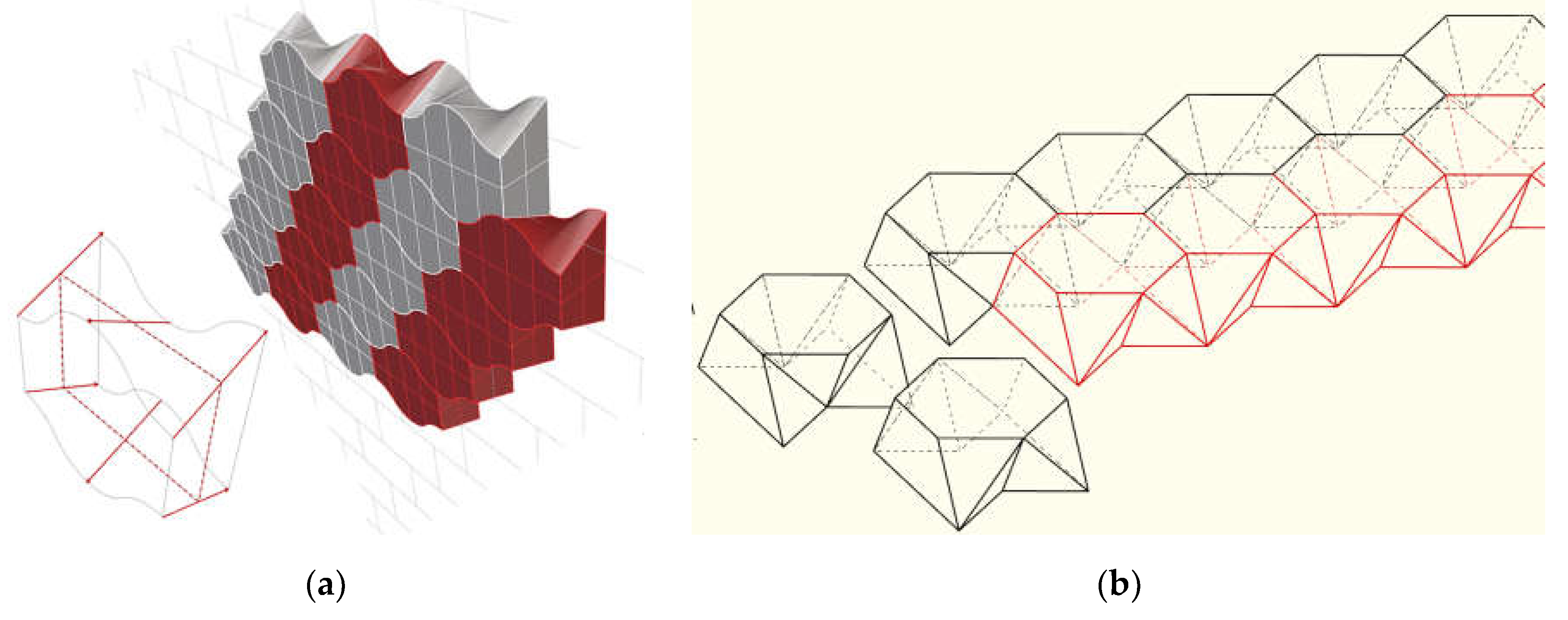
Figure 22.
Fabrication of the TIA of osteomorphic blocks material system: a) laser-cut, plastic sheet moulds with folding perofations; b) laser-cut MDF frames increase moulds’ rigidity during.
Figure 22.
Fabrication of the TIA of osteomorphic blocks material system: a) laser-cut, plastic sheet moulds with folding perofations; b) laser-cut MDF frames increase moulds’ rigidity during.
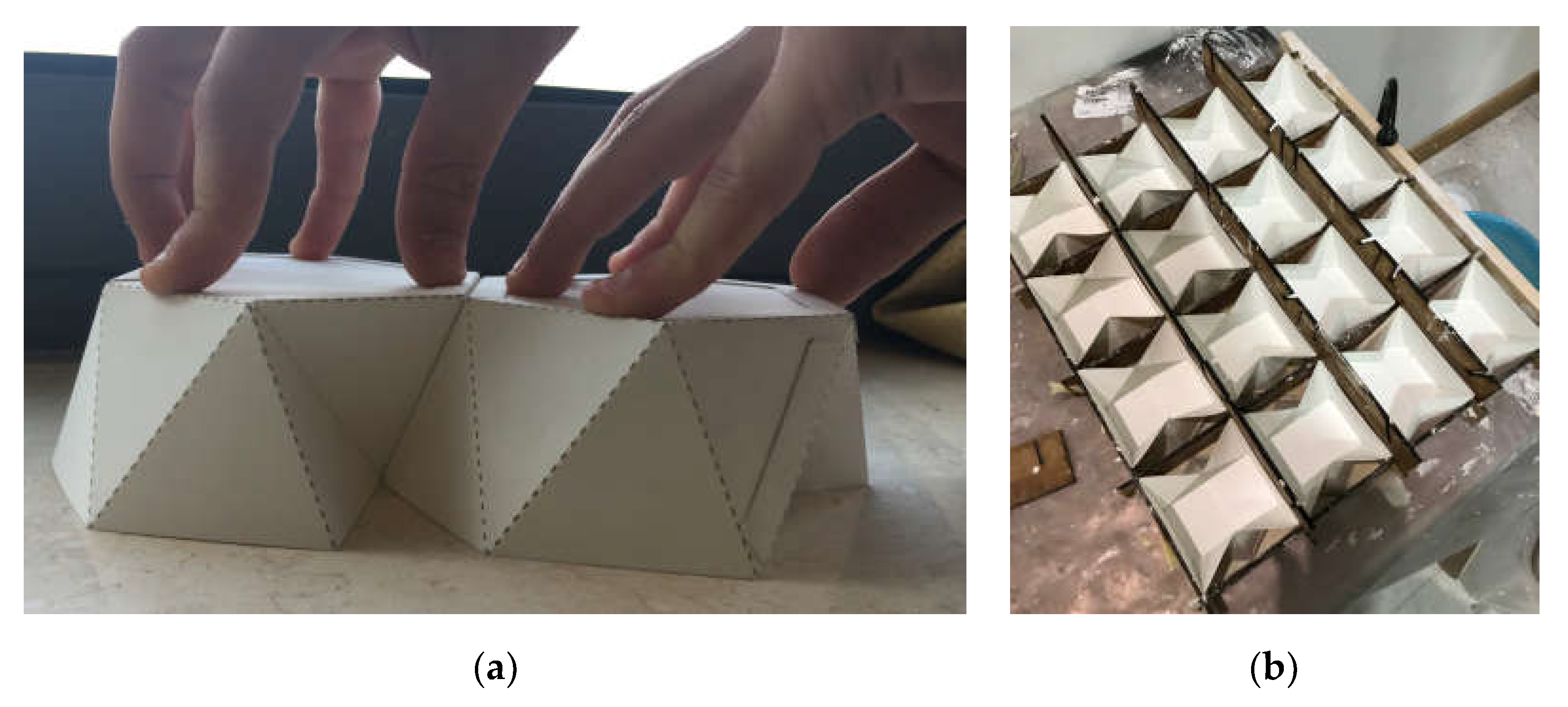
Figure 23.
Fabricated TIA of osteomorphic blocks material system: a) individual blocks, two configuration types; b) TIA of planar osteomorphic blocks (Models by Gabriel Barthet).
Figure 23.
Fabricated TIA of osteomorphic blocks material system: a) individual blocks, two configuration types; b) TIA of planar osteomorphic blocks (Models by Gabriel Barthet).
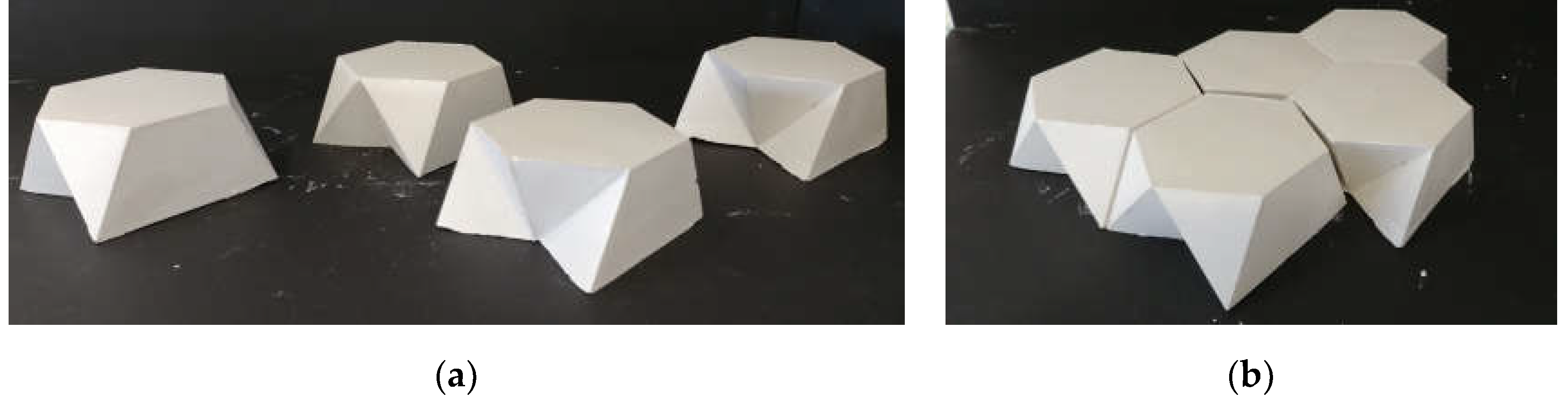
Figure 24.
Second procedural logic for a material system based on TIA of planar osteomorphic blocks: a) single typology individual planar osteomorphic blocks and its TIA (Diagram by Gabriel Barthet; b) fabricated TIA of planar osteomorphic blocks did not achieve the interlocking (Models by Gabriel Barthet).
Figure 24.
Second procedural logic for a material system based on TIA of planar osteomorphic blocks: a) single typology individual planar osteomorphic blocks and its TIA (Diagram by Gabriel Barthet; b) fabricated TIA of planar osteomorphic blocks did not achieve the interlocking (Models by Gabriel Barthet).
Disclaimer/Publisher’s Note: The statements, opinions and data contained in all publications are solely those of the individual author(s) and contributor(s) and not of MDPI and/or the editor(s). MDPI and/or the editor(s) disclaim responsibility for any injury to people or property resulting from any ideas, methods, instructions or products referred to in the content. |
© 2024 by the authors. Licensee MDPI, Basel, Switzerland. This article is an open access article distributed under the terms and conditions of the Creative Commons Attribution (CC BY) license (http://creativecommons.org/licenses/by/4.0/).
Copyright: This open access article is published under a Creative Commons CC BY 4.0 license, which permit the free download, distribution, and reuse, provided that the author and preprint are cited in any reuse.


