
Submitted:
26 June 2024
Posted:
27 June 2024
You are already at the latest version
Abstract
The demand for improved service in mobile networks is always increasing. That means signal transmission with higher capacity is required. To achieve that goal a combined optical and wireless link using double polarization multiplexing has been developed. A high quality signal transmission is achieved by applying high polarization extinction ratio. The new concept is validated by experiments varying the bit rate and fiber length. A signal with 12 Gbit/s bit rate was transmitted over a 25 km long combined link with about 1.10-8 bit error rate. That result is much better than the already published data which were measured on links transmitting information with 2.5 Gbit/s bit rate. The polarization multiplexing technique is very practical for capacity enhancement in a specific section of an existing optical fiber by inserting a new link into it without deploying a new fiber.
Keywords:
double orthogonal polarization
; capacity enhancement
; combined optical – wireless link
; polarization extinction ratio
1. Intoduction
The increasing demand for improving the service of future mobile networks requires signal transmission with higher capacity. The radio over fiber link provides proper connections between a center station and its radio base stations due to its high capacity and low loss.
Enhancing the capacity of existing optical links is an important issue. Presently for that, the polarization division multiplex (PDM) method is applied together with wavelength division multiplex (WDM) [1,2,3,4]. In that approach the polarization of the adjacent channels is orthogonal. This way the wavelength difference between the adjacent channels can be reduced resulting in modest capacity enhancement.
The polarization division multiplexing technique has already been investigated in some publications [4,5]. Most of them were theoretical studies or simulations [5,6,7,8]. These papers considered applications for short distances with relatively low bit rates, usually 2.5 Gbit/s. The combination of polarization division multiplexing and wavelength division multiplexing is a complex procedure therefore it needs more sophisticated system architecture.
In advanced mobile networks millimeter wave carrier frequencies and higher bit rates (4-12 Gbit/s) are required [9]. To achieve that goal a new approach is needed.
In the present paper a novel approach, the double polarization multiplexing (DPM) method is investigated. In that case the optical beam has simultaneously two orthogonal polarizations or by other words it has double polarization. In the orthogonal polarizations of the beam the information to be transmitted is different. The simulation results of the double polarization multiplex approach are promising [10,11]. Some experiments have already been carried out on optical fibers using double polarization multiplexing [11,12]. However, experimental investigations on combined fiber optic and wireless links have not been done in details. This paper presents an experimental optical-wireless link and its measured results to validate the usefulness and advantages of the double polarization multiplexing in combined optical-wireless links.
Recently mobile networks more frequently utilize optical interconnections instead of microwave links. The optical fiber has many advantages like avoiding electromagnetic interference, providing extreme wide band and very low loss. The increasing demand for higher signal transmission capacity requires new system architectures. There are two main approaches for capacity enhancement, the application of several wavelengths or increasing the bit rate. Both methods have advantages and drawbacks. In the first method the combination and separation of different wavelengths are cumbersome and the nonlinearity of fiber has limitation on the total capacity. In the other method at higher bit rates the link will be more complex and the bit rate is finally limited by the dispersion of fiber. These methods are used mainly in back-bone connections.
In mobile networks the optical link is used for connecting the central station to the radio base stations. Usually these links are not in the route of optical fiber back-bone connections. Therefore individual links are deployed. These links have to be cost effective concerning both their deployment and operation. For this application the double polarized link is the best choice due to its simplicity and flexibility. In that case the independency of the channels is a serious requirement. To achieve that goal the polarization extinction ratio is to be high enough, i.e. at least 22 dB at the output of the transmitter.
In the following first the properties of information transmission over an optical fiber link and over a wireless link are investigated. Then the developed combined optical-wireless link is presented along with detailed measurement results.
2. Information Transmission over an Optical Fiber Link
Information transmission over an optical fiber link suffers from several problems. Besides attenuation an important difficulty is caused by fiber dispersion which results in pulse broadening.
In the case of an intensity modulated signal there are two side bands around the carrier wave. When that wave is propagating over a fiber there will be a time difference between the detected pulses obtained from the two side bands. As the bit rate is increasing the frequency difference between the side bands and the carrier is also increasing. Consequently the delay between the detected signals is also increasing. At the same time with increasing bit rate the pulse time is decreasing, As a consequence of the two effects the pulse broadening becomes more and more significant.
The pulse broadening is characterized by the percentage value of the ratio of delay time and pulse time:
Here is the time delay, Tp is the pulse time, D is the dispersion coefficient in ps / (nm.km), L is the fiber length in km, Rb is the bit rate, is the optical wavelength in nm, c is the speed of light in vacuum, and fb is the bit frequency which is taken as the half of bit rate: fb = Rb / 2.
Pulse broadening causes inter-symbol interference (ISI). However, pulse broadening also dependent on the decision level and processing time of receiver detection method. The percentage of pulse broadening is shown in Figure 1 as a function of bit rate. The parameter of curves is the fiber length: red: 5 km, brown: 3 km, blue: 1 km. In this example the Corning SMF-28e type single mode fiber is used which has a low dispersion coefficient: D = 12.5 ps / (nm.km) at the optical wavelength of 1.55 µm.
At a specific dispersion coefficient and fiber length limitation is obtained for the bit rate to be transmitted and this way the capacity of fiber link is limited. That limitation can be somewhat overcome by applying a dispersion compensation method.
3. Information Transmission by a Radio Frequency Wireless Link
In the mobile network free space wave propagation at a radio frequency (RF) is used for the connection between the mobile terminal and the radio base station. That connection is significantly influenced by two-path or multi-path propagation effects. These effects also cause pulse broadening due to the propagation time difference between the direct and reflected waves. That time difference is proportional to the difference between the different lengths of the direct and reflected waves. In the mobile network the wave propagation routes are very different therefore their effects have to be treated individually in each case.
In the wireless domain multipath wave propagation is a substantial problem. Multipath wave propagation causes not only the degradation of the received signal (fading) but also pulse broadening and this way inter-symbol interference. The reason is that in case of multipath propagation the lengths of the propagation routes are different. In general there is a direct wave between the transmitter and the receiver and a reflected wave which arrives from the transmitter to the receiver reflected by an object. The reflected wave propagates along a longer way and therefore with some delay. The delay between the direct wave and the reflected wave is proportional to the difference in their propagation lengths.
Here Lr is the propagation length of reflected wave, Ld is the propagation length of direct wave and c is the velocity of light in vacuum. The total delay is caused by the sum of all reflected waves. It is very cumbersome to consider every reflection for summing up their effects on the total delay. That needs case by case investigation.
Pulse broadening abbreviated as “pb” is obtained as the ratio of delay time Δτ to pulse time TP:
Here TP is the pulse time or pulse duration. The pulse time is the reciprocal of the bit rate (Rb). Thus pulse broadening can be expressed also as:
Pulse broadening causes inter-symbol interference (ISI). However, pulse broadening also dependent on the decision level and processing time of receiver detection method. The effect of pulse broadening is also influenced by the power difference between the direct and reflected waves. The reflected wave intensity is determined by the radiation intensity in the direction of reflected wave and on the reflection coefficient of reflecting object.
The inter-symbol interference problem caused by pulse broadening can be reduced significantly by applying OFDM (orthogonal frequency division multiplexing) modulation format in the radio over fiber link and also in the wireless domain. The OFDM modulation format applies a high number of subcarriers and therefore the modulated subcarriers have a much lower bit rate. Consequently in case of OFDM signal transmission pulse broadening plays a smaller role, however, other problems appear. OFDM modulation is very sensitive to the linearity of system and also due to its power peaks it needs a high dynamic range.
In the design of a complete radio over fiber and wireless link in case of OFDM modulation an optimum solution can be achieved. The tolerable inter-symbol interference determines the acceptable pulse broadening and this way the optimum number of subcarriers. This way the linearity requirement and the peak intensity can be reduced significantly.
4. Radio over Fiber and Wireless Link with Double Polarization Multiplexing
The capacity of fiber link can be enhanced by using double polarization of the optical wave. Double polarization means two orthogonal polarizations at the same wavelength. This way double capacity of fiber link is provided.
To ensure the orthogonality of the waves a special wave generation method has to be applied. The quality of orthogonality is characterized by the polarization extinction ratio:
PER = Ip / Icp
Here Ip is the intensity of a linear polarized wave and Icp is the intensity of an orthogonally polarized linear wave. The polarization extinction ratio has to be high enough not only at the generation of the optical wave but also at the reception side or by other word at the end of optical fiber link.
Another important characteristic is the polarization mode dispersion (PMD). In the case when PMD is sufficiently small it doesn’t reduce PER significantly along the fiber link.
There are two procedures to generate the optical wave with two orthogonal polarizations. In one approach a common optical source is applied for creating two optical information transmitting channels such a way that the optical beam is generated by a common laser source and it is divided in two equal parts. That means the two optical beams are coherent. In the other approach two independent optical sources are applied with the same wavelength. That means the two optical beams are incoherent. The incoherency helps to reduce the effect of cross modulation between the two channels having orthogonal polarization. In the following the incoherent approach is applied and investigated. In both cases the independence of the channels is only based on the polarization difference, i.e. on the polarization orthogonality. That means there is no need for optical filtering to combine and separate the two channels. That is a big advantage of the double polarization multiplexing method.
The experimental validation of double polarized signal transmission is presented in this section. First the method for generating two orthogonal optical beams is discussed. The optical beams are adjusted by polarization controllers to orthogonal polarization states using a special procedure described in the following.
The output beam of a laser diode has elliptical polarization. For generating an optical beam with two orthogonal polarizations a high polarization extinction ratio is needed at both polarizations. Therefore the laser beam has to be linear or by other word it has to have only one polarization state. That goal is achieved by applying a polarization filter which suppresses the unwanted orthogonal polarization of laser beam. As seen in Figure 2 the laser beam propagating through the optical polarization filter (denoted as filter) which produces a linear beam is led to the input of a polarization beam splitter (PBS) via a polarization angle rotator (denoted as angle). The polarization angle is adjusted to get maximum output intensity at X output and minimum output intensity at Y output of the polarization beam splitter. The polarization state of Y output is perpendicular to the polarization state at X output. The ratio of the intensities at X and Y outputs provides the PER value, which is dependent on the efficiently of optical filtering and also on the PER of polarization beam splitter. For good operation of double polarized fiber link PER has to be at least 22 dB [11,12]. The former procedure is carried out with the beams of both lasers, as seen in Figure 2. However, it is done with opposite polarization in case of LD1 than in case of LD2. That means in the latter case, i.e. in case of LD2 the polarization angle is adjusted to get maximum output intensity at Y output and minimum output intensity at X output of PBS.
A combined radio over fiber and wireless link with double polarization has been developed and investigated by measurements. The block diagram of the experimental set up is shown in Figure 3. There are two optical sources with almost the same frequency: 193.5 THz. Their output powers are: 12 dBm and 13 dBm. The polarizations of laser beams are adjusted to orthogonal polarization by polarization controllers which have a polarization filter and a polarization angle rotator as seen in Figure 2. The two optical beams are then modulated by two independent random data streams in Mach-Zehnder optical modulators. The PER is checked at the outputs of Mach-Zehnder modulators by the procedure shown in Figure 2. In the optical link the Corning SMF-28e type single mode fiber is used with low dispersion coefficient: D = 12.5 ps / (nm.km) at 1.55 µm optical wavelength
In the transmitter a local oscillator laser is inserted with 45° polarization angle compared to the two orthogonal polarizations. Very high frequency stability is necessary because two millimeter wave signals are generated at the reception side by mixing the beams of the two lasers with the beam of local oscillator laser working at 193.440 THz frequency. The mixing product is then 60 GHz. The optically transmitted information is optically detected by the receiver and it is further transmitted by the wireless link. The millimeter wave signals containing their original information are amplified, filtered and radiated to the subscribers. In the experiment this situation is investigated in the laboratory.
The generated 60 GHz signal is radiated and received by horn antennas using two perpendicular polarizations. This way an integrated optical millimeter wave link is created and tested. Applying the polarization multiplexing method also in the wireless link its capacity is increased as well. Therefore we can transmit either more information or we can transmit the same information improving this way the reliability of wireless connection.
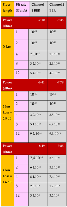
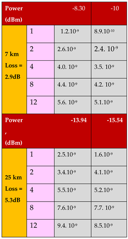
Table 4 presenting the picture of two transmitter and two receiver antennas with two orthogonal polarizations at 60 GHz. They are composed into a joint picture. In the real measurement the transmitter and receiver antennas were in an about 3 m distance from each other in the laboratory. As seen there is a pair of antennas with vertical polarization and another pair of antennas with horizontal polarization. The quality of the signal transmission has been checked by bit error rate measurements. The measurement results are presented in Table 1.
The wave propagation problems of the wireless link cannot be tested properly in an indoor environment like a laboratory because in the laboratory there are many reflections and these increase the pulse broadening significantly. That is more observed first of all at higher bit rates. Therefore that measurement is only a feasibility study. In spite of that, good transmission was obtained even over a 25 km long fiber as it is shown in Table 1. In most applications the fiber length is less than 7 km.
5. Applications
The applications of radio over fiber link with double polarization are presented for several cases in the following. The radio over fiber (RoF) link can be applied for different connections in a mobile network. One example is when a central station has to be connected to a radio base station. In that case the aim is to perform most of signal processing in the central station to obtain a very simple radio base station. That arrangement is especially important in the millimeter wave band because in that case we have smaller cells and therefore more radio base stations. In this application the radio over fiber link is the best choice because besides transmitting information it also can be used to produce millimeter wave (MMW) signals in the radio base station. The MMW signals also carry the original information. Therefore, the generated MMW signals can be radiated without any further signal processing (except amplification and filtering). Figure 5 presents this application.
In another application the two channels with orthogonal polarization have also two different optical local oscillators in the transmitter. This way, after reception two different millimeter wave signals are obtained by optical mixing. Then these signals can be used for two different radio base stations.
As a further application the radio over fiber link connects the center station with a node of the optical link. In the node the radio frequency carrier is generated by optical mixing. That signal is used to connect the node with the radio base station by the wireless RF link. Figure 6 presents this application.
The polarization multiplexing technique is very practical for capacity enhancement in a specific section of an existing optical link by inserting a new link into it. The arrangement of block diagram presented in Figure 7 is suitable for connections between a central station and the radio base stations of a mobile network.
For creating double polarization of an optical beam the same procedure is used as in Figure 2. Therefore in Figure 7 the laser beam propagating through the optical polarization filter (denoted as filter) - which produces a linear beam – is propagating across a polarization angle rotator (denoted as angle) in both arms of the block diagram. Before connecting the two optical beams to the polarization beam combiner (PBC) the same adjustment is used as in Figure 2 to obtain a double polarized beam at the output of PBC at the transmitter side. The two links are propagating over a fiber with double polarization to the receiver side where they are separated by a polarization beam splitter (PBS). That approach is very flexible which makes it well applicable in mobile networks. Its further advantage is that it can utilize the existing optical network without deploying a new fiber or cable for capacity enhancement.
In some cases a new link has to be inserted into a channel of a fiber with many wavelength division multiplex (WDM) channels. For that case Figure 8 shows a proper block diagram. Applying that block diagram a channel is coupled out from the WDM channels by a fiber Bragg grating (FBG) type filter. Then a new link can be inserted into the decoupled channel utilizing the method shown in Figure 2 providing this way a double polarized wave carrying two channels. Due to double polarized wave propagation the FBG filter and the output optical circulator carries two orthogonal polarizations.
Figure 9 presents the block diagram of the receiver side of the new link inserted into a channel of a fiber carrying many wavelength division multiplex (WDM) channels. Due to double polarized wave propagation the FBG filter and the input optical circulator carries two orthogonal polarizations.
6. Conclusion
A combined radio over fiber and wireless link with double polarization multiplexing has been developed and investigated by measurements. Over the fiber two optical beams with orthogonal polarization carries independent information, doubling the link capacity this way. As a local oscillator an additional laser beam is inserted with 45° polarization angle. By optical mixing two millimeter waves are generated at 60 GHz ferquency. The two millimeter waves also with orthogonal polarization carry the information in the wireless section between the radio base station and the subscribers. To ensure a high quality signal transmission a special procedure has been applied which provides high polarization extinction ratio.
The developed combined radio over fiber and wireless link was constructed and tested by detailed measurements. In the experimental investigations the bit rate and fiber length were varied. A signal with 12 Gbit/s bit rate was transmitted over a 25 km long combined optical and wireless link with about 1.10-8 bit error rate. That result is much better than the already published data which were measured on links transmitting signals with 2.5 Gbit/s bit rate. The measurement results proved the high quality performance of the combined radio over fiber and wireless link applying double polarization multiplexing.
The polarization multiplexing technique is very practical for capacity enhancement in a specific section of an existing optical link by inserting a new link into it. That approach is very flexible which makes it well applicable in mobile networks. Its further advantage is that it can utilize the existing optical network without deploying a new fiber or cable for capacity enhancement.
Acknowledgement
The authors acknowledge Andreas Stöhr and Matthias Steeg at University of Duisburg, Germany for the excellent consultations. The authors also acknowledge the CA16220 EUIMWP EU COST project and the K132050 Hungarian OTKA project for useful cooperation in their research.
References
- Rochat, E., Walker, S.D. and Parker, M.C.: “Polarisation and wavelength division multiplexing at 1.55 μm for bandwidth enhancement of multimode fibre based access networks”. Optics Express, 12(10), pp. 2280-2292, 2004.
- Yao, X.S., Yan, L.S., Zhang, B., Willner, A.E. and Jiang, J.: “All-optic scheme for automatic polarization division demultiplexing”. Optics Express, 15(12), pp. 7407-7414, 2007. [CrossRef]
- Perez, J., Morant, M., Llorente, R. and Marti, J.: “Joint distribution of polarization multiplexed UWB and WiMAX radio in PON,” Journal of Lightwave Technology, vol. 27, no. 12, pp. 1912–1919, 2009. [CrossRef]
- Morant, M., Pérez, J. and Llorente, R.: „Polarization Division Multiplexing of OFDM Radio-over-Fiber Signals in Passive Optical Networks”, Advances in Optical Technologies, Hindawi Publ., Article ID 269524, 2014. [CrossRef]
- Yoshida, Y., Takami, Y., Inudo, S., Kitayama, K.I., Kanno, A., Yamamoto, N. and Kawanishi, T.: “On the channel capacity of polarization-multiplexed coherent radio-over-fiber transmissions at millimeter-wave bands”, IEEE International Conference on Communications (ICC), pp. 1-6, 2016.
- Johny, J., Shashidharan, S., Sudheer, S.K. and Kumar, K.S.: “Design and Simulation of a Radio Over Fiber System with Chromatic Dispersion and Polarisation Mode Dispersion Compensation”. IEEE Symposium on Photonics and Optoelectronics, pp. 1-4, 2012.
- Core, M.T.: “Cross polarization interference cancellation for fiber optic systems,” Journal of Lightwave Technology, vol. 24, no. 1, pp. 305–312, 2006. [CrossRef]
- Nelson, L.E., Nielsen, T.N. and Kogelnik, H.: “Observation of PMD-induced coherent crosstalk in polarization-multiplexed transmission,” IEEE Photonics Technology Letters, vol. 13, no. 7, pp. 378–390, 2001. [CrossRef]
- Berceli, T. and Herczfeld, P.R.: Microwave Photonics-A Historical Perspective, IEEE Transactions on Microwave Theory and Techniques, Vol. 58, No. 11, pp. 2992-3000, 2010.
- Badraoui, N. and Berceli, T.: “Behaviour of Cross Polarization on Radio over Fiber Links”. IEEE 11th International Symposium on Communication Systems, Networks & Digital Signal Processing (CSNDSP), pp. 1-5, 2018.
- Badraoui, N. and Berceli, T.: “Enhancing capacity of optical links using polarization multiplexing”. Optical and Quantum Electronics, 51(9), p. 310, Springer, 2019. [CrossRef]
- Badraoui, N. and Berceli, T.: “Crosstalk reduction in fiber links using double polarization”, Optical and Quantum Electronics, 52, p. 200, Springer, 2020. [CrossRef]
Figure 1.
Pulse broadening as a function of bit rate. The parameter of curves is the fiber length: red: 10 km, brown: 5 km, blue: 3 km.
Figure 1.
Pulse broadening as a function of bit rate. The parameter of curves is the fiber length: red: 10 km, brown: 5 km, blue: 3 km.
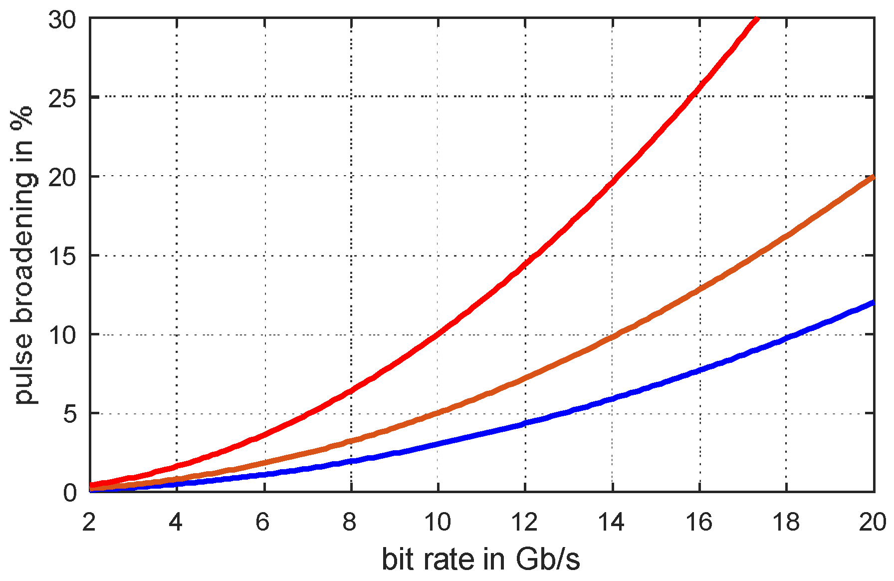
Figure 2.
Block diagram for producing two orthogonal linear laser beams.
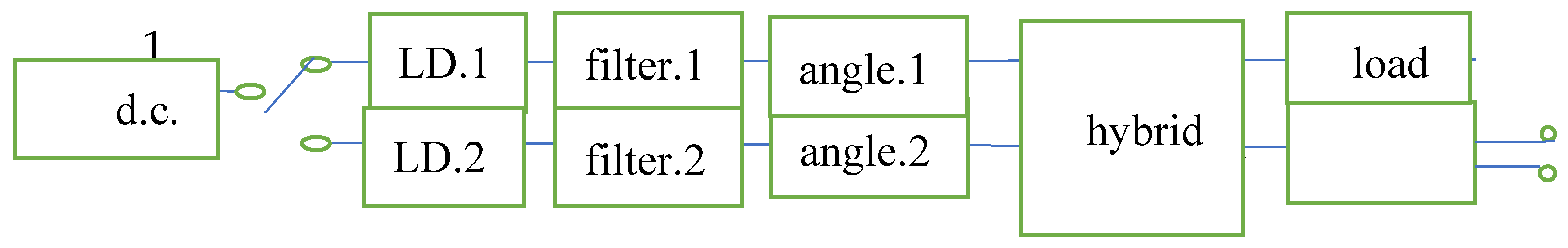
Figure 3.
Block diagram of the combined radio over fiber and wireless link.
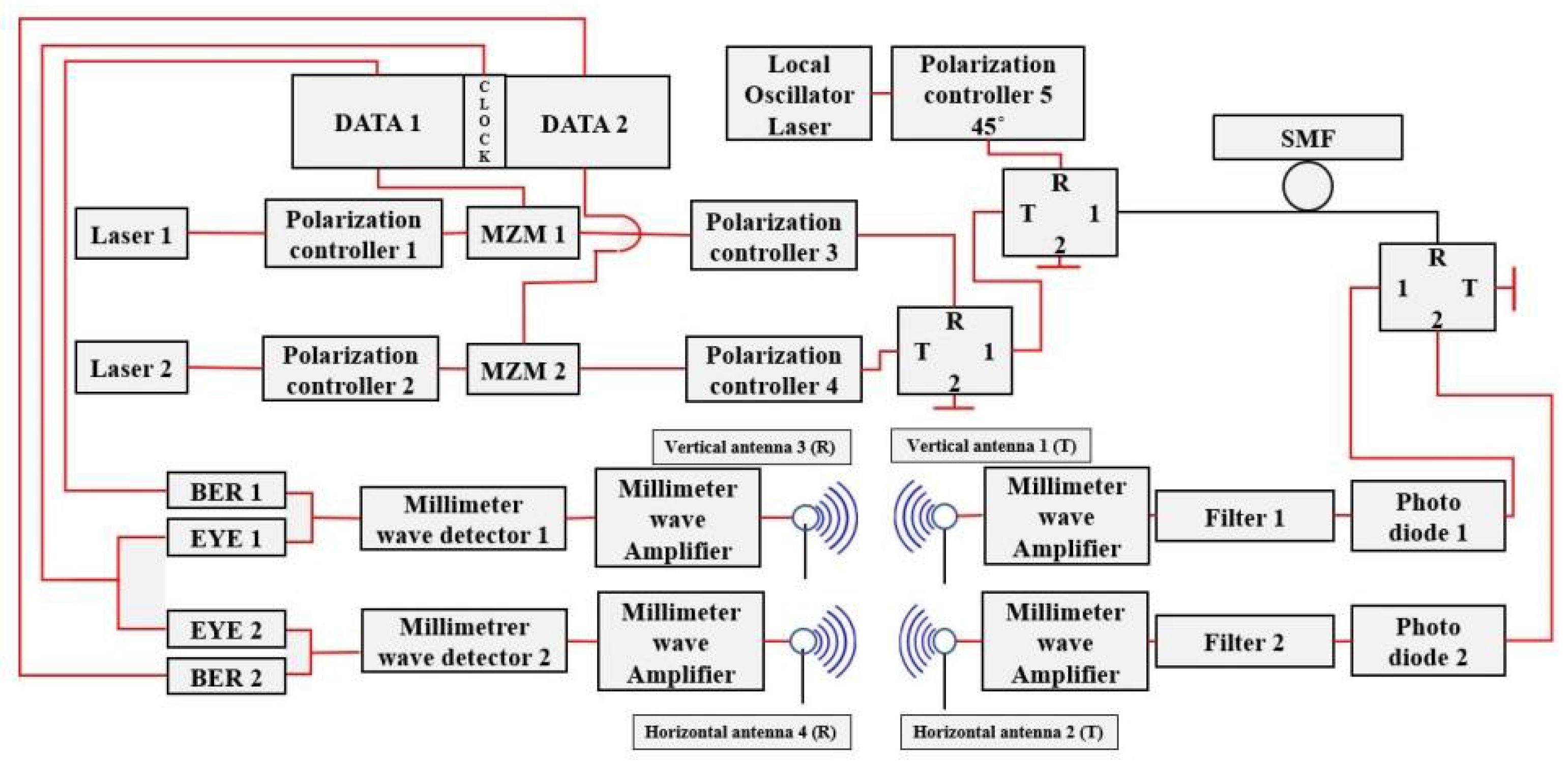
Figure 4.
Picture of the laboratory measurement set up.
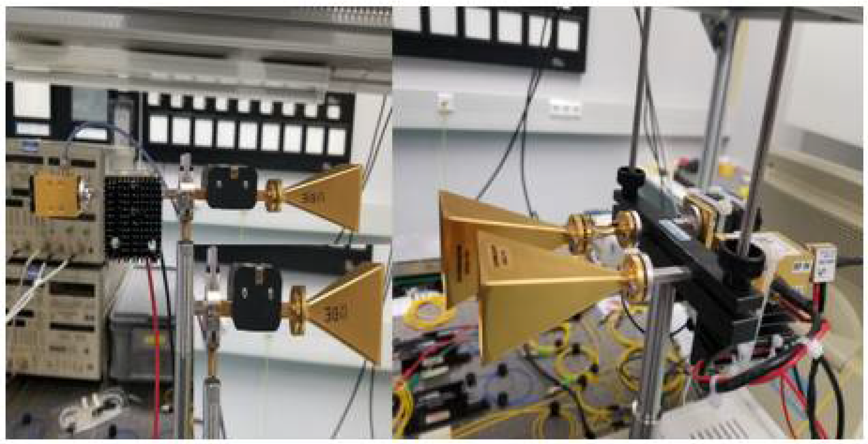
Figure 5.
Optical link between the center station and radio base station, wireless links between the radio base station and subscribers.
Figure 5.
Optical link between the center station and radio base station, wireless links between the radio base station and subscribers.
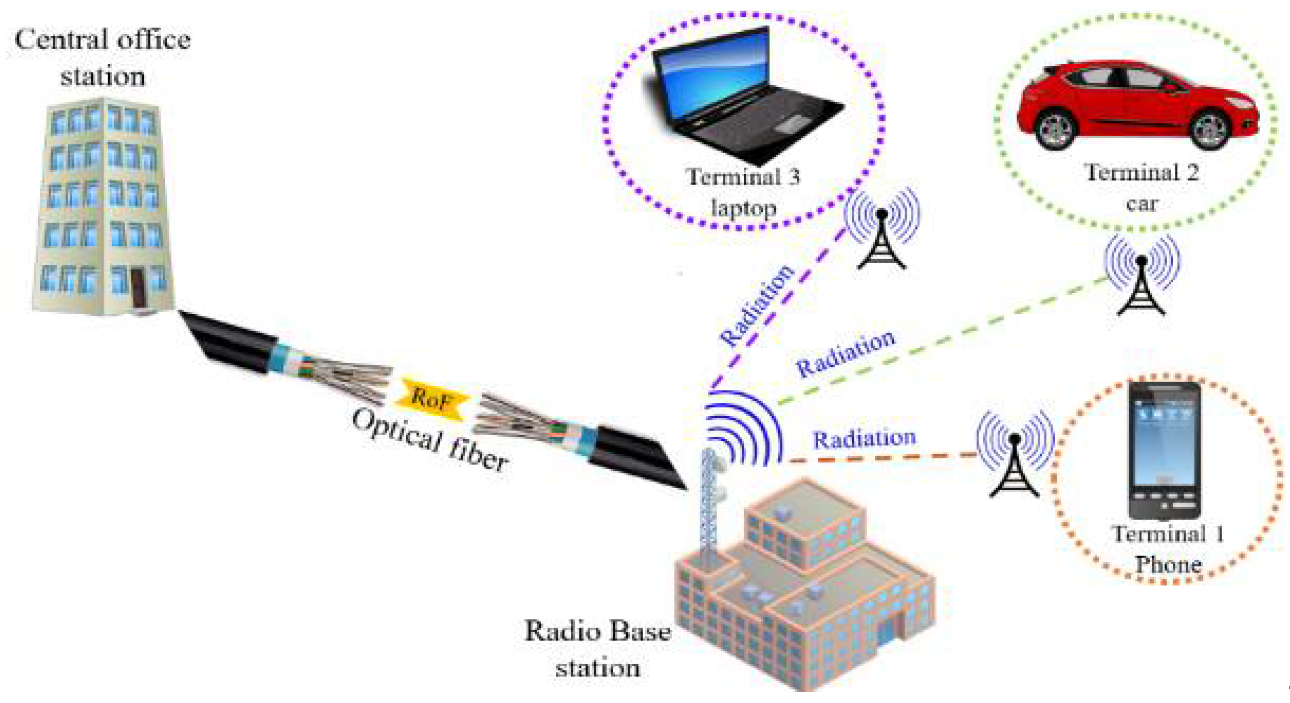
Figure 6.
Optical link between the center and a node, wireless link between the node and a radio base station.
Figure 6.
Optical link between the center and a node, wireless link between the node and a radio base station.
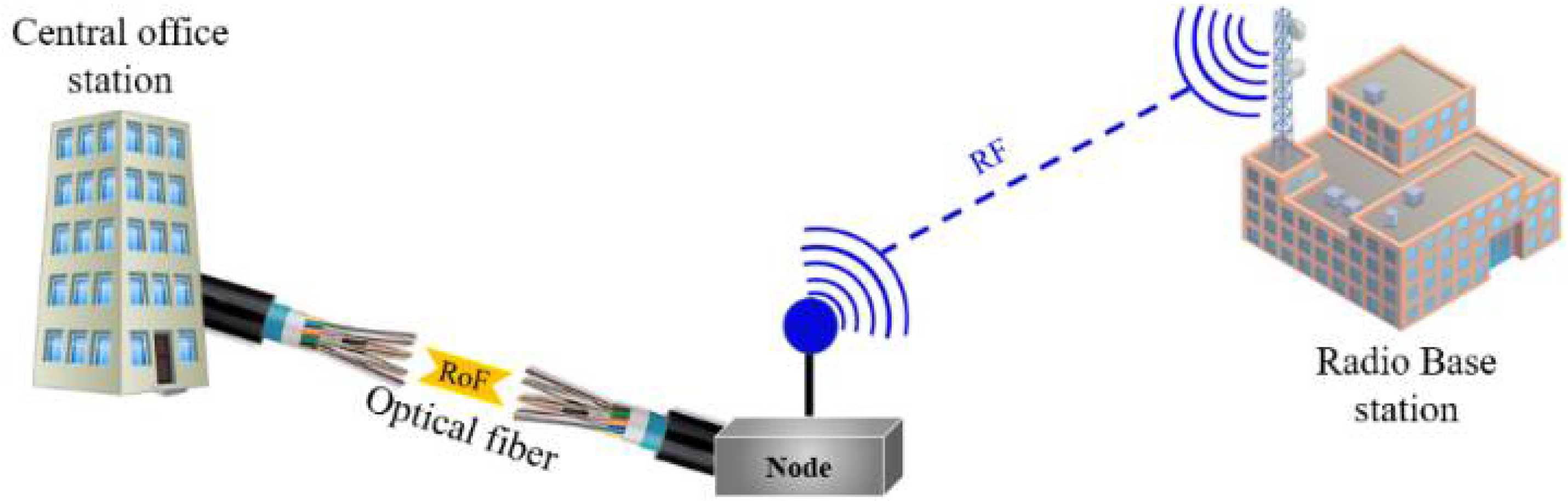
Figure 7.
Block diagram of inserting a new link into an existing link.
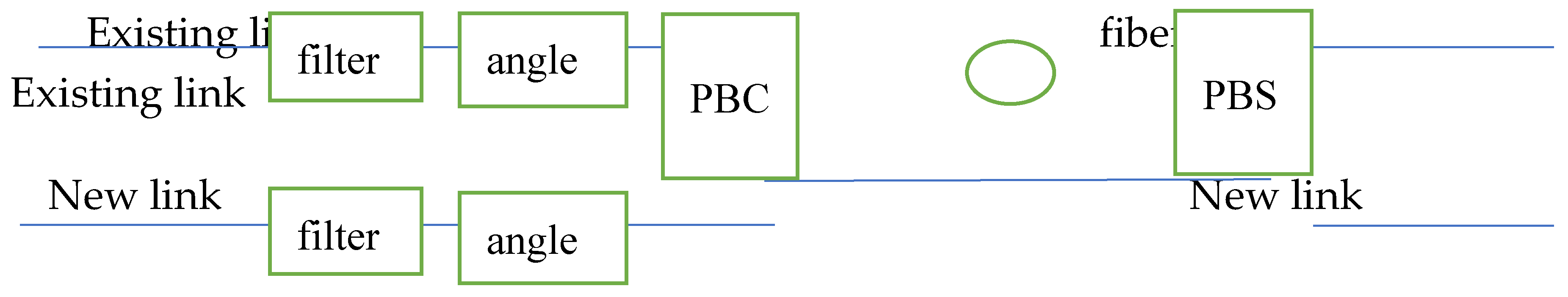
Figure 8.
Block diagram of the transmitter side for inserting a new link into a channel of a fiber carrying many wavelength division multiplex (WDM) channels.
Figure 8.
Block diagram of the transmitter side for inserting a new link into a channel of a fiber carrying many wavelength division multiplex (WDM) channels.
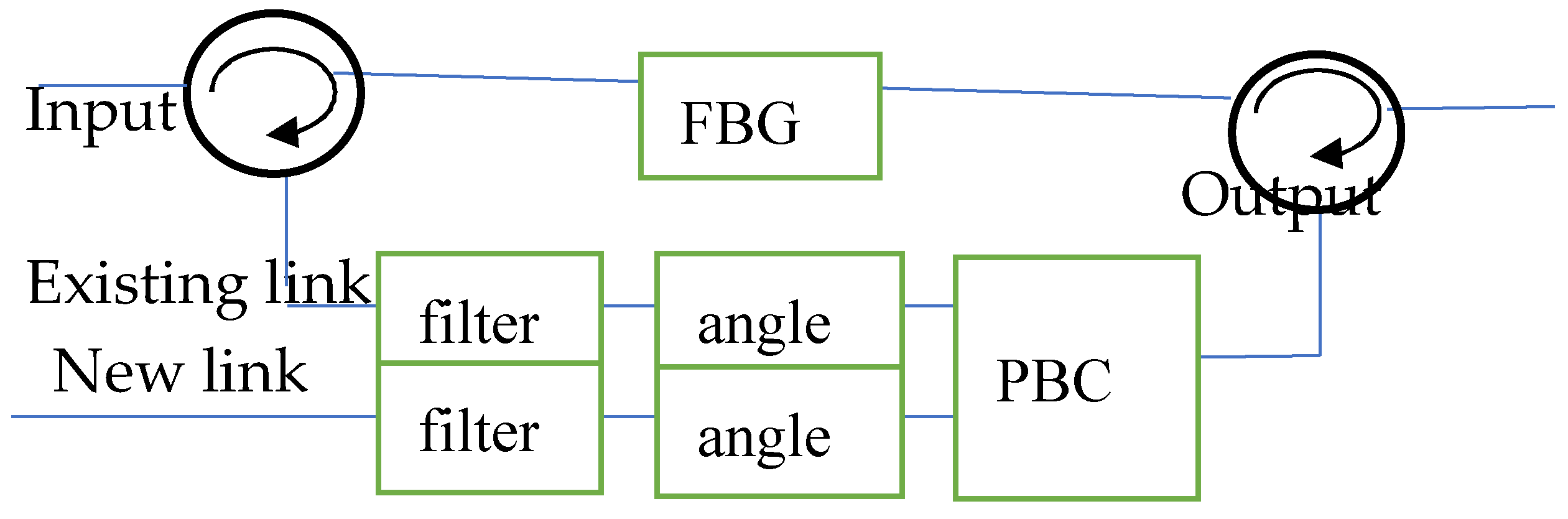
Figure 9.
Block diagram of the receiver side of the new link inserted into a channel of a fiber carrying many wavelength division multiplex (WDM) channels.
Figure 9.
Block diagram of the receiver side of the new link inserted into a channel of a fiber carrying many wavelength division multiplex (WDM) channels.
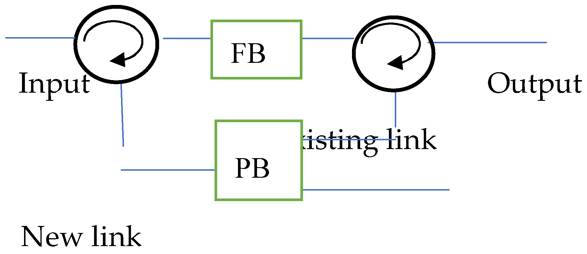

Table 1.
Measurement results of the combined optical and wireless link with double polarization multiplexing
Table 1.
Measurement results of the combined optical and wireless link with double polarization multiplexing
Disclaimer/Publisher’s Note: The statements, opinions and data contained in all publications are solely those of the individual author(s) and contributor(s) and not of MDPI and/or the editor(s). MDPI and/or the editor(s) disclaim responsibility for any injury to people or property resulting from any ideas, methods, instructions or products referred to in the content. |
© 2024 by the authors. Licensee MDPI, Basel, Switzerland. This article is an open access article distributed under the terms and conditions of the Creative Commons Attribution (CC BY) license (http://creativecommons.org/licenses/by/4.0/).
Copyright: This open access article is published under a Creative Commons CC BY 4.0 license, which permit the free download, distribution, and reuse, provided that the author and preprint are cited in any reuse.


