Submitted:
28 May 2024
Posted:
28 May 2024
You are already at the latest version
Abstract
A flexible asymmetric supercapacitor (ASCs) is successfully developed by using the composite of MoO3 and graphene oxide (GO) electrochemically deposited on carbon cloth (CC) (MoO3/rGO/CC) as the negative electrode, the MnO2 deposited on CC (MnO2/CC) as the positive electrode and Na2SO4/polyvinyl alcohol (PVA) as gel electrolyte. The results show that the introduction of GO layer can remarkably increase the specific capacitance of MoO3 from 282.7 F g-1 to 341.0 F g-1. Furthermore, the combination of such good electrode materials and a neutral gel electrolyte renders the fabrication of high-performance ASC with a large operating potential difference of 1.6 V in 0.5 mol L-1 Na2SO4 solution of water. Furthermore, the ASCs exhibit excellent cycle ability and the capacitance can maintain 87 % of its initial value after 6000 cycles. The fact that a light-emitting diode can be lighted up by the ASCs indicates the device’s potential applications as energy storage devices. The encouraging results demonstrate a promising application of the composite of MoO3 and GO in energy storage devices.
Keywords:
Carbon cloth
; reduced graphene oxide
; MoO3
; MnO2
; asymmetric supercapacitors
1. Introduction
Supercapacitors (SCs) are potential energy storage devices and have been extensively studied owing to their characteristics such as high energy density, fast charge/discharge rates and long cyclic life [1,2]. They have been widely applied in hybrid electric vehicles, backup energy systems and mobile electronic devices, etc. [3]. With the increasing requirement for personal electronics in modern society, to make electronic devices flexible and portable has become the research hotspot at present. Correspondingly, flexible and portable electronic devices need a new type of energy storage equipment different from traditional ones to be designed [4,5,6,7,8]. Therefore flexible energy storage devices, especially flexible asymmetric SCs (ASCs) have received extensive attention because they can provide higher energy density compared with symmetric SCs [9,10,11,12,13,14,15].
To fabricate flexible ASCs (FASCs), it is necessary and crucial to select the current collector and active materials because they directly affect the performance of FASCs [19,20,21]. As a new flexible conductor, carbon cloth (CC) has attracted widespread attention in recent years for preparing SCs’ electrodes due to its three-dimensional (3D) network structure and reasonable electrochemical stability [16]. By using CC as a substrate, conducting polymers deposited on it has shown high energy density and power density. For example, Horng et al. have successfully fabricated polyaniline (PANI) nanowire/CC nanocomposite electrodes by employing electrochemical deposition, and the PANI has displayed an excellent specific capacitance of (Cs) 1079 F g-1 [17]. A flexible electrode of CC/MoS2/PANI has been prepared via combining the facile hydrothermal method and in situ polymerization method, the PANI of this electrode shows a Cs value of 972 F g-1 at a current density of 1 A g-1 which is significantly higher than that of CC/MoS2 (425 F g-1) [18].
Transition metal oxides are the other commonly used electrode materials for SCs, at first the noble metal oxides such as RuO2 [22] and RhOx [23], etc. are extensively studied because of their high faradic capacitance and good conductivity. Despite the excellent capacitive performances, the practical application of the noble metal oxides is limited by their scarcity and high price. Therefore numerous researches have focused on the replacement of precious metal oxides with cheap transition metal oxides [24] due to their comparative theoretical Cs, availability and relatively reversible characteristics. Up to date, the hierarchical porous MnO2 nanoflakes have been prepared by a rapid hydrothermal method without any templates and show the maximum Cs of 268 F g-1 [25]Transition metal oxides are the other commonly used electrode materials for SCs, at first the noble metal oxides such as RuO2 [22] and RhOx [23], etc. are extensively studied because of their high faradic capacitance and good conductivity. Despite the excellent capacitive performances, the practical application of the noble metal oxides is limited by their scarcity and high price. Therefore numerous researches have focused on the replacement of precious metal oxides with cheap transition metal oxides [24] due to their comparative theoretical Cs, availability and relatively reversible characteristics. Up to date, the hierarchical porous MnO2 nanoflakes have been prepared by a rapid hydrothermal method without any templates and show the maximum Cs of 268 F g-1 [25]. Different from the usually used electrode material of MnO2 which possesses capacitive property at positive potential range, MoO3 exhibits capacitance at negative potential range and has attracted much attention [26,27,65]. Furthermore, the other attractive nature of MoO3 is its particular 2D layered structure, which is conducive to provide high power density for capacitor applications because of the adequate intercalation between the layers and electrolyte ions [28]. In fact, the capacitive property of MoO3 is strongly affected by its, for example, MoO3 exhibits Cs value of about 280, 110 and 30 F g-1 when it shows nanoplate, nanowire and nanorod morphologies respectively [29]. Recently, Pujari et al. have found that hexagonal MoO3 micro rods display a Cs of 194 F g-1 [30]. Despite the efforts on MoO3, the Cs values are still not very high due to its low conductivity. Therefore, it is necessary to develop a strategy to prepare the composites with relatively high conductivity by adding some highly conductive materials [30,31,32,33,34,35]. Among the various methods for composites, co-electrochemically depositing active materials and carbon materials is proved to be effective approach; as precursor of graphene, graphene oxide (GO) has attracted great interest for fabricating composites recently because of GO’s easy manipulation in the aqueous medium, and high specific area [36,37].
In this work, we choose CC as a flexible substrate to deposit MoO3 as negative electrode, during which the graphene oxide (GO) is added to form the composite of MoO3 and reduced GO (rGO) through electrochemical co-deposition. It is expected that the introduction of rGO not only improves the conductivity of the composite but also increase the Cs of MoO3. The electrode prepared by electrochemically depositing MnO2 on CC is used as positive electrode, MoO3/rGO/CC as negative electrode and NaSO4/polyvylene oxide as gel electrolyte and separator to assembly ASCs. By using this strategy, we hope that the FASCs can possess the high operating potential differences, energy density and power density.
Therefore, metal oxide and conductive polymer composites with CC as the substrate are promising electrode materials for SCs.
For instance, conductive polymers can be designed as flexible electrodes due to their high energy storage, low cost, and easy preparation. Conductive polymers are able to form composites with carbon materials or metal oxides, which improves their electrochemical properties. In particular, conductive polymers decorated on CC exhibit improved specific capacitance and power capacity when used as composite electrodes.
2. Experimental
2.1. Reagents and Materials
Manganese (II) acetate (Mn(Ac)2·4H2O), ammonium molybdate [(NH4)2MoO4], ammonium chloride, polyvinyl alcohol (PVA, Mw 85000), and sodium sulfate (Na2SO4) were purchased from Aladdin Chemical Co. and used without further purification. Conductive CC substrate was obtained from Shanghai Chuxi Industrial Co. Ltd.
2.2. Preparation of the Negative Electrodes
Pretreatment of the CC: The commercial CC was first immersed in concentrated nitric acid (HNO3, 68 wt. %) and then heated at 60 °C for about 6 hours in a water bath to make the surface hydrophilic. Subsequently, the CC was washed with distilled water thoroughly and then soaked in distilled water for use.
Electrochemically depositing MoO3 on CC: The used electrolyte here (30.0 mL) was an aqueous solution of (NH4)2MoO4 (0.05 mol L-1) and NH4Cl (0.05 mol L-1) and its pH value were adjusted to 2.0 by acetic acid. The pretreated CC slices (1×1 cm2) were used as working electrode, a Pt sheet as counter electrode and a saturated calomel electrode (SCE) as reference electrode; by using a constant current density of 4 mA cm-2, different amounts of MoO3 were deposited on CC by controlling the depositing time (700-1300 s). According to the capacitance measured by using a three-electrode system in 0.5 M Na2SO4 electrolyte, the MoO3/CC prepared from 1000 s was used to assemble the ASCs.
Electrochemically depositing MoO3/rGO on CC: First, GO was prepared by oxidizing 300 mesh graphite powder according to the modified hummer method [38]. The sample of MoO3/rGO/CC prepared by using electrochemical deposition method according to 2.2 was used as a work electrode here to deposit GO on the surface of MoO3/CC by cyclic voltammetry (CV) method in different concentrations of GO solution, and the obtained electrode was defined as MoO3/rGO/CC. The appropriate GO in the electrolyte is selected by optimizing the deposition time and the CV number. Place MoO3/rGO/CC in a vacuum oven overnight. The electrochemical performance test was carried out in a three-electrode system after drying.
2.3. Fabrication of the Electrode of MnO2/CC
By using a three-electrode system, MnO2/CC was also prepared via an electro-deposition method. In the mixing solution of Mn(Ac)2 (0.05 mol L-1) and Na2SO4 (0.05 mol L-1), the MnO2 was deposited on the pre-treated CC at a constant current of 4.0 mA cm-2 when the CC was used as working electrode, a Pt plate as counter electrode and a saturated calomel electrode (SCE) as reference electrode, and the amount of MnO2 was controlled by depositing time (600-1400 s). After the deposition process was completed, the electrode of MnO2/CC was washed by deionized water and dried in a vacuum oven at 70 °C overnight. The electrode of MnO2/CC prepared from different depositing time was defined as MnO2/CC-t (t was the depositing time).
2.4. Fabrication of the FASC Devices
Gel electrolyte: 1.0 g PVA powders were slowly added into 10.0 mL solution of Na2SO4 (0.5 mol L-1) under stirring, then the mixture was heated to 85 °C until the mixture became transparent, then the solution was naturally cooled to room temperature for utilization.
Assemble of FASC device: Firstly, the CC was first pretreated with HNO3 at 60 °C to remove the sizing agent on the surface of the fibers. Then, MnO2/CC and MoO3/rGO/CC were fabricated using a facile electrodeposition method. MnO2 or MoO3 or rGO was grown on the CC substrate using three-electrode configuration with CC as the working electrode, Pt piece as the counter electrode, and Hg/HgCl2 as the reference electrode. Finally, MoO3/rGO/CC as negative electrode and MnO2/CC as positive electrode.According to the capacitance measured by using the three-electrode system, it was clear that the capacitances of the MoO3/rGO/CC negative electrode and MnO2/CC positive electrode can be balanced when geometric area of the two electrodes was the same. When the FASC device was assembled, the Na2SO4/PVA gel electrolyte was uniformly covered on one electrode such as MnO2/CC, then the other electrode (MoO3/rGO/CC) was placed on the face of MnO2/CC which was coved by Na2SO4/PVA gel electrolyte and followed by pressure to make the two electrodes together, subsequently, the assembled devices were frozen in refrigerator for 30 min. Finally, the fabrication of FASC was completed after the frozen device was placed at room temperature to unfreeze.
2.5. Characterization and Electrochemical Measurements
The electrodes’ morphologies were observed by using a scanning electron microscope (SEM, JEOL 6701) operating at accelerating voltage of 10 kV. Attenuated total reflection-Fourier transforming infrared spectra (ATR-FTIR) were collected on a Nicolet iS50R (USA) instrument in a range of 400-4000 cm-1 with a resolution of 2 cm-1. X-ray photoelectron spectroscopy (XPS ESCAL-ab 220i-XL, VG Scientific, England) was performed by using a monochromic Al Ka as source.
The capacitive measurements of the electrode materials and the ASCs were carried out on a CHI 660E electrochemical work station. Three-electrode system was used to test the electrodes’ capacitive performance, the prepared positive and negative electrodes were used as the working electrode, a Pt sheet as the counter electrode and a SCE as reference electrode. Aqueous solution of Na2SO4 (0.5 M) was used as electrolyte for testing MnO2 and MoO3 capacitive properties, respectively. The potential windows were set to 0-1.0 V for positive electrode (MnO2) and -1.0-0 V for negative electrode (MoO3) during the cyclic voltammetry (CV) and galvanostatic charge/discharge (GCD) tests. Using the two-electrode system, the performances of the FASCs were evaluated. The CV measurements were carried out in a voltage range of 0.0-1.6 V and the scan rates were varied from 2 to 100 mV s-1. The GCD tests were performed at various current densities from 1.0 to 12.0 mA cm-2 with cut off voltage of 0.0-1.6 V. In the frequency range of 0.01-100000 Hz, the electrochemical impedance spectra (EIS) were measured by employing a disturbance with 5 mV potential amplitude. The cyclic stabilities were estimated on the same instrument by successive CV scan at 100 mV s-1.
3. Results and Discussion
3.1. Structural Properties Characterization of All Samples
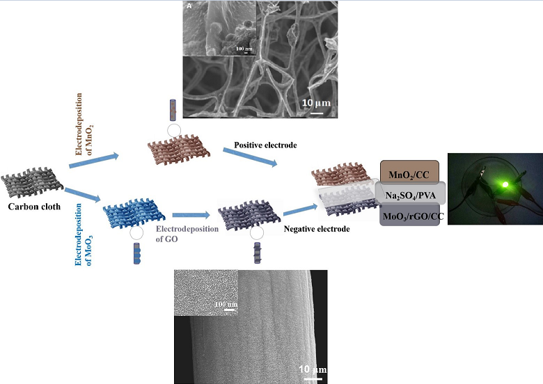
Figure 1 depicts a schematic illustration of the procedure for the preparation of electrodes and the device. Based on the flexibility and conductivity of CC, and the potential ranges of electrochemical activity for MoO3 and MnO2 [39,40], the FASCs can be fabricated by using MoO3/rGO/CC as negative electrode and MnO2/CC as positive electrode in Na2SO4/PVA gel electrolyte.
From the SEM image shown in Figure 2, it is found that fibers contained in CC have the clean surface with some groves (Figure 2A), the diameter of the fibers is relatively uniform and many accumulated pores are observed among the fibers (Figure 2B). When the molybdenum oxide has been electrochemically deposited, the surface of the fiber will be covered by a layer of molybdenum oxide, it can be seen from the image of MoO3/CC (Figure 2C) the fiber is uniformly wrapped by a layer of molybdenum oxide, but the film has many cracks which are caused during the drying process. Under the large magnification, the corrugated morphology is observed (Figure 2D), this rough surface structure is favorable to increase the surface area of MoO3. Notably, the film thickness and mass loading can be well controlled by changing the deposition time. When the deposition time is 1000 s, the well “skeleton/skin” architecture with the carbon fiber as the skeleton and MoO3 as the skin can be obtained [41,42].
As shown in Figure 2E and F, the surface of CC is decorated with flaked rGO, and the embedded enlarged image (Figure 2G) clearly shows that GO makes the smooth surface of carbon smooth. In addition, uniform rGO nanosheets form 2D layered structure on the surface of MoO3/rGO/CC, which increases the surface area and improves the electrical conductivity compared with the blank CC. SEM results showed that the surface of MoO3/CC composite was successfully coated with a layer of rGO.
To confirm the nature of the product, the as-prepared materials have been characterized by X-ray diffraction. From the Figure 3, it can be found all the samples show the obvious peaks related to the substrate of CC or rGO, but no distinguishable peaks can be seen for the components of MoO3 and MnO2, which may be attributed to the fact that the formed MoO3 and MnO2 are amorphous or the crystalline is too small, or the weak diffraction peaks related to MoO3 and MnO2 are covered up by the diffraction peak of C due to the small amount of the active materials [16,43,44,45]. FTIR spectroscopy provides details of the band characteristics of the components of composites. As shown in Figure S3, no strong characteristic peaks are seen in the wave number ranged from 400 to 2000 cm-1. The spectrum of MoO3/CC exhibits three major peaks located at 955, 826 and 753 cm−1, which are attributed to the Mo=O stretching vibration of the terminal oxygen, and the symmetric and asymmetric stretching vibration of the bridging oxygen in Mo-O-Mo, respectively [46]. However, the IR spectrum for GO/MoO3/CC exhibit the characteristic of rGO [16] besides the MoO3’s characteristics, confirming that rGO has successfully loaded on the surface of MoO3/CC.
Analysis of the XPS can reveal the chemical states of the samples of MnO2/CC (a), MoO3/rGO/CC (b), MoO3/CC (c) and CC (d) (Figure 4A). All the spectra show the XPS peaks related to the element of Mn or Mo together with that of C and O. In particular, the characteristic doublet of Mn2p (Figure 4B) 2p1/2 (654.1 eV) and Mn2p 2p3/2 (642.4 eV) from MnO2/CC identify the formation of MnO2 due to the difference between the two peaks of 11.7 eV [48]. Similarly, the double peaks observed at 233.0 and 236.2 eV in MoO3/rGO/CC can be contributed to Mo 3d5/2 and Mo 3d3/2 respectively due to spin-orbit splitting (Figure 4D) [45]. According to the fitted results, it can find that the components of MoO2 and MoOx exhibit in the sample besides the component of MoO3 [47]. By comparison, in the Mo 3d spectrum of the MoO3/rGO/CC composite, the aforementioned peaks shift to 232.8 and 236.0 eV, respectively, where such 0.2 eV offset results from the interaction between rGO and MoO3. The peak intensity in the MoO3/CC spectrum is higher than that in the MoO3/rGO/CC spectrum, indicating that the experimental molybdenum content in MoO3/CC is higher than that in MoO3/rGO/CC [16].
3.2. The Electrochemical Properties of MoO3/rGO/CC
The galvanostatic method is used to deposit MoO3 on the pretreated CC, and the depositing current and depositing time are optimized by changing the current and depositing time. Firstly, the deposition current is optimized in the same deposition solution by changing the current keeping the depositing charge amount constant. The obtained electrodes’ CV curves are tested by employing three-electrode system, according to the formulae shown in the supporting information, the specific capacitances are calculated and the plot of Cm value versus the currents is drawn in Figure S1. It can be seen that the Cm value reaches a maximum value of 282.8 F g-1 at a current of 6 mA. Subsequently, the current is fixed at 6 mA to changing the deposition time to optimize the time. It can be found in Figure S1B, the maximal Cm value of 283.5 F g-1 achieves when the depositing time is 1000 s. Therefore, we use the condition of 6 mA constant current and depositing time of 1000 s to prepare the electrode at following experiments. In order to improve the performance, the electrodes of MoO3/CC are used as working electrode to electrochemically deposit the rGO in different GO solution, from Figure S1C, we can find when the concentration of GO solution is about 7.0 mg mL-1, the modified electrode shows largest Cm value. Therefore, the electrode prepared at above mentioned condition will be evaluated in detail.
It is clear from Figure 5A that the electrode of MoO3/rGO/CC exhibit far larger surrounded CV area than MoO3/CC at the same scan rate, while the capacitance contribution from CC can be completely neglected. The CV curves of the MoO3/rGO/CC electrode exhibit a similar shape at different potential scan rates from 5 to 100 mV s-1, based on the curves, the Cm values of MoO3/rGO/CC are calculated and shown in Figure 5C, it is clear that the Cm values of MoO3/rGO/CC decrease with the increase of the scan rates because the limited diffusion time for ions when the scan rate is large, and has the largest Cm value of 341.0 F g-1 which is much higher than that of MoO3/CC electrode (282.8 F g-1) at 1 mV s-1 scan rate, which can be attributed to the conductive rGO sheets on the MoO3 surface provide a shorter transmission path for the electrons and the electrolyte ions. The Cm values for the MoO3/rGO/CC show a downward trend with the increase of the scan rates. The GCD curves of the MoO3/rGO/CC electrode in potential range of -1.0-0 V (Figure 5D) display almost symmetric shapes at different current densities, the iR drop is small at low current density and increases with the increment of the current densities, the Cm values obtained from the GCD curves are similar to those from CV profiles. The good capacitive performance of MoO3/rGO/CC can be attributed to the close contact between the carbon fiber and the MoO3 layer, the more transporting route for electrons provided by the coated rGO sheets on the MoO3 besides the fast and efficient charge transport originated from the 3D CC framework.
At an open circuit potential, the EIS spectrum has been recorded within the frequency range from 100 kHz to 0.01 Hz to reveal the kinetic property of MoO3/rGO/CC. It is clear that a semicircle in the high frequency region and a linear spike in the low frequency region are appeared in the Nyquist plots (Figure 5E) [49]. The typical small semicircle in the high frequency region is related to the Faradaic charge transfer resistance (Rct) of the electrode material, which is associated with electrical conductivity and the charge transfer path between the electrode material and the electrolyte [50]. The profile can be fitted by using the Zview software, from the fitted Nyquist plots, the Rct value of GO/MoO3/CC electrode is 1.824 Ω, indicating the enhanced the charge transportation provided by the decorated rGO on the surface. The electrochemical stability of the electrodes has been also investigated by successive CV scanning at a scan rate of 100 mV s-1 (Figure 5F), it is found that MoO3/rGO/CC can retain 88.6 % of its initial capacitance, indicating good cycling stability.
3.3. Electrochemical Performance of the FASC
To prepare ASC device, the capacitance of negative electrode must match that of positive electrode. The matching of the two electrodes’ capacitance can be determined by the charge balance relationship of Q+ = Q-, where Q+ is the charge stored in positive electrode and Q- the charge in negative electrode. To the flexible devices, the charge storage at each electrode relies on the Ca, operating voltage window (∆V), and geometric surface area (S), the charge storage can be given by equation (1):
To satisfy Q+ = Q-, the areal balance can be expressed by using the relationship as (2) [70]:
The positive electrode has been prepared by using CC as substrate via electrochemical depositing method. The conditions for depositing MnO2 have been optimized and the results are shown in the supporting information (Figure S2). It can be seen that the electrode prepared at a current of 4 mA for 1000 s exhibits the optimal Cm value (343.3 F g-1), and the electrodes prepared under this condition are further investigated and used to assemble the devices. In 0.5 mol L-1 Na2SO4 solution, the MnO2/CC electrodes exhibit CV curves with quasi rectangle shape when the sweep rates are low, indicating fairly good performances of MnO2/CC (Figure 6A). From the plot of the Cm versus the scan rates, it is easy to find that the Cm values decrease with the increment of scan rates, and the Cm value can still remain 45.1% of its largest Cm value at scan rate of 100 mV s-1 (Figure 6B), indicating a fairly good rate capability. Based on the results obtained from CV tests in three-electrode system, the area ratio of MoO3/rGO/CC to MnO2/CC and is set to 1:1 for the ASC device. Therefore, the devices are constructed by using the Na2SO4/PVA gel electrolyte to separate the negative electrode of MoO3/rGO/CC and positive electrode of MnO2/CC. By employing the two-electrode system, the CV profiles of the device are recorded within different voltage windows at scan rate of 20 mV s-1 (Figure 6C and D) to determine the operating potential difference. It is clear that the operating potential difference of the device can be expanded to 1.6 V since the potential window for MoO3/rGO/CC electrode is -1.0-0 V, while MnO2/CC electrode is 0-1.0 V which are determined by three-electrode system [51,52,53]. Notably, the CV curves of the ASC device resemble those observed for MnO2/CC electrode measured in the three-electrode system, the redox couples stably maintain from scan rate of 2 to 100 mV s-1 (Figure 6E). The Cm values for the ASC (Figure 6F) also show a downward trend with the increase of the scan rates. At the scan rate of 2 mV s-1, the device shows a Cm value of about 98.3 F g-1 (Ca of 226.4 mF cm-2).
The GCD curves of the ASC device (Figure 7A) show quasi-linear and symmetrical shapes, which suggest a rapid voltage-current response and fairly good electrochemical reversibility. The slight deviation from straight line can be attributed to the pseudo capacitance existed in the devices. Under the low current density, the GCD curves display a small iR drops, but with the increase of the current density, the iR drops increase obviously, which are mainly originated from the internal resistance of the devices. At current density of 1.0 mA cm-2, the Cm of the device can reach to about 112.8 F g-1 and Ca of 193.5 mF cm-2. It is expected that the Cm values of the ASC decrease gradually with the increment of the current density due to ions diffusion limitation (Figure 7B), which is similar to CV results.
EIS experiment is conducted to further examine the detailed electrochemical properties of the ASC device (Figure 7C). In the high-frequency region, the small intercept between the semicircle and Z' axis indicates a low equivalent series resistance [54,55]. In the medium frequency range, the radius of the semicircle [56] is related to the Rct which represents the resistance produced by the Faradaic reaction of the electrode with the electrolyte. At the low frequencies, a line nearly perpendicular to the Z' axis reveals the fairly good capacitive feature because vertical line usually indicates ideal capacitance. The cyclic stability of the ASC device has also been evaluated by successive CV scan within the potential difference range of 0-1.6 V. After 6000 cycles, the capacitance of ASC device can retain 88.1 % of its initial value, indicating good cycling stability, expressing relatively proper electrochemical stability of this kind of ASC device (Figure 7D).
To evaluate the device’s practical properties, the energy and power densities have been calculated based on the discharging branch of GCD curves are by using the formulae of supplementary materials and shown in the Ragone plots (Figure 8A). It's obvious that the ASC shows an energy density of 32.1 Wh kg-1 at 533.3 W kg-1; more remarkably, even when the power density of device reaches 5333.3 W kg-1, the energy density still remains 20.2 Wh kg-1, which is better than other devices previously reported (Table 1) due to the electrode's high electrochemical capacitance and good rate capability, demonstrating the potential application of these kind of electrode materials. Furthermore, a LED can be driven by the fully charged tandem cells (Figure 8B), demonstrating the potentially practical application. The combination of good pseudo capacitive materials supported on CC substrate and a mild gel electrolyte provides an efficient approach to fabricate high-performance ASCs with good cycling.
4. Conclusions
An easy and straightforward method for depositing high-active pseudo capacitive materials on carbon cloth hosts (MoO3/rGO/CC and MnO2/CC) has been developed. The conductive carbon cloth with good mechanical flexibility not only provides efficient support for loading active materials to fabricate hybrid ASCs, but also facilitates fast ion and electron transport at the electrode/electrolyte interface. The introduction of rGO layer can remarkably improve the specific capacitance of the MoO3 layer on the carbon fibers from 282.7 to 341.0 F g-1. Furthermore, the assembled ASC by using the electrochemically deposited electrodes and a neutral gel electrolyte Na2SO4/PVA possesses a large operation potential of 1.6 V, exhibits a high energy density of 32.08 Wh kg-1 at the power density of 0.53 kW kg-1, and 5.33 Wh kg-1 at 20.2 kW kg-1. Furthermore, the ASC exhibits good cycle ability and the capacitance can maintain 87.1 % of its initial value after 6000 cycles. The ability of that two ASC devices connected in series are able to light up a LED that indicates its potential applications as energy storage devices.
Acknowledgments
This work was supported by the applied Science and technology plan project of Xinzhou (20220508) and Science and technology innovation project of higher education in Shanxi Province (2023L295) and sponsored by the Institute of Optoelectronic Functional Materials.
References
- W. He: Bo W., M.T. Lu, Z. Li, H. Qiang, Fabrication and Performance of Self-Supported Flexible Cellulose Nanofibrils/Reduced Graphene Oxide Supercapacitor Electrode Materials, Molecules 12 (2020) 2793-2807. [CrossRef]
- G.Q. Zhou, G. Liang, W. Xiao, L.L. Tian, Y.H. Zhang, R. Hu, Y. Wang, Porous α-Fe2O3 Hollow Rods/Reduced Graphene Oxide Composites Templated by MoO3 Nanobelts for High-Performance Supercapacitor Applications, Molecules 6 (2024) 1262-1351. [CrossRef]
- S. Saha, P. Samanta, N.C. Murmu, T. Kuila, A review on the heterostructure nanomaterials for supercapacitor application, J. Energy Storage 17 (2018) 181-202. [CrossRef]
- Z. Liu, J. Xu, D. Chen, G.Z. Shen, Flexible electronics based on inorganic nanowires, Chem Soc Rev 44 (2015) 161-192. [CrossRef]
- B.C. Kim, J.Y. Hong, G.G. Wallace, H.S. Park, Recent Progress in Flexible Electrochemical Capacitors: Electrode Materials, Device Configuration, and Functions, Adv Energy Mater 5 (2015) 1500959. [CrossRef]
- X.F. Wang, X.H. Lu, B. Liu, D. Chen, Y.X. Tong, G.Z. Shen, Flexible Energy-Storage Devices: Design Consideration and Recent Progress, Adv Mater 26 (2014) 4763-4782. [CrossRef]
- X. Lu, M. Xu, G. Wang, Flexible solid-state supercapacitors: design, fabrication and applications, Energ Environ Sci 7 (2014) 2160-2181. [CrossRef]
- L. Li, Z. Wu, S. Yuan, X.B. Zhang, Advances and challenges for flexible energy storage and conversion devices and systems, Energ Environ Sci 7 (2014) 2101-2122. [CrossRef]
- W.D. He, C.G. Wang, H.Q. Li, X.L. Deng, X.J. Xu, T.Y. Zhai, Ultrathin and Porous Ni3S2/CoNi2S4 3D-Network Structure for Superhigh Energy Density Asymmetric Supercapacitors, Adv Energy Mater 7 (2017) 1700983. [CrossRef]
- C. Guan, W. Zhao, Y.T. Hu, Z.C. Lai, X. Li, S.J. Sun, H. Zhang, A.K. Cheetham, J. Wang, Cobalt oxide and N-doped carbon nanosheets derived from a single two-dimensional metal-organic framework precursor and their application in flexible asymmetric supercapacitors, Nanoscale Horizons 2 (2017) 99-105. [CrossRef]
- N. Jabeen, A. Hussain, Q.Y. Xia, S. Sun, J.W. Zhu, H. Xia, High-Performance 2.6 V Aqueous Asymmetric Supercapacitors based on In Situ Formed Na0.5MnO2 Nanosheet Assembled Nanowall Arrays, Adv Mater 29 (2017) 1700804. [CrossRef]
- M.F. El-Kady, R.B. Kaner, Scalable fabrication of high-power graphene micro-supercapacitors for flexible and on-chip energy storage, Nat Commun 4 (2013) 1475-1484. [CrossRef]
- H. Gwon, H.S. Kim, K.U. Lee, D.H. Seo, Y.C. Park, Y.S. Lee, B.T. Ahn, K. Kang, Flexible energy storage devices based on graphene paper, Energ Environ Sci 4 (2011) 1277-1283. [CrossRef]
- S.W. Lee, B.S. Kim, S. Chen, Y. Shao-Horn, P.T. Hammond, Layer-by-Layer Assembly of All Carbon Nanotube Ultrathin Films for Electrochemical Applications, J Am Chem Soc 131 (2009) 671-679. [CrossRef]
- Y.W. Zhu, S. Murali, M.D. Stoller, K.J. Ganesh, W.W. Cai, P.J. Ferreira, A. Pirkle, R.M. Wallace, K.A. Cychosz, M. Thommes, D. Su, E.A. Stach, R.S. Ruoff, Carbon-Based Supercapacitors Produced by Activation of Graphene, Science 332 (2011) 1537-1541. [CrossRef]
- J.Z. Ling, H.B. Zou, W. Yang, W.S. Chen, Facile fabrication of polyaniline/molybdenum trioxide/activated carbon cloth composite for supercapacitors, Journal of Energy Storage 20 (2018) 92-100. [CrossRef]
- Y.Y. Horng, Y.C. Lu, Y.K. Hsu, C.C. Chen, L.C. Chen, K.H. Chen, Flexible supercapacitor based on polyaniline nanowires/carbon cloth with both high gravimetric and area-normalized capacitance, J. Power Sources 195 (2010) 4418-4422. [CrossRef]
- H. Zhang, G. Qin, Y. Lin, D. Zhang, H. Liao, Z. Li, J. Tian, Q. Wu, A novel flexible electrode with coaxial sandwich structure based polyaniline-coated MoS2 nanoflakes on activated carbon cloth, Electrochim. Acta 264 (2018) 91-100. [CrossRef]
- L.G.H. Staaf, P. Lundgren, P. Enoksson, Present and future supercapacitor carbon electrode materials for improved energy storage used in intelligent wireless sensor systems, Nano Energy 9 (2014) 128-141. [CrossRef]
- Y. Huang, Y. Huang, M.S. Zhu, W.J. Meng, Z.X. Pei, C. Liu, H. Hu, C.Y. Zhi, Magnetic-Assisted, Self-Healable, Yarn-Based Supercapacitor, ACS Nano 9 (2015) 6242-6251. [CrossRef]
- M.X. Wang, Q.L.Yan, F. Xue, J. Zhang, J.Q. Wang, Design and synthesis of carbon nanotubes/carbon fiber/reduced graphene oxide/MnO2 flexible electrode material for supercapacitors, J. PHYSICS AND CHEMISTRY OF SOLIDS 119 (2018) 29-35. [CrossRef]
- B. Mendoza-Sánchez, T. Brousse, C. Ramirez-Castro, V. Nicolosi, P.S. Grant, An investigation of nanostructured thin film α-MoO3 based supercapacitor electrodes in an aqueous electrolyte, Electrochim. Acta 91 (2013) 253–260. [CrossRef]
- T. Liu, W.G. Pell, B.E. Conway, Self-discharge and potential recovery phenomena at thermally and electrochemically prepared RuO2 supercapacitor electrodes, Electrochim. Acta 42 (1997) 3541–3552. [CrossRef]
- M.J. Klink, M.E. Makgae, A.M. Crouch, Physico-chemical and electrochemical characterization of Ti/RhOx –IrO2 electrodes using sol–gel technology, Mater. Chem. Phys. 124 (2010) 73–77. [CrossRef]
- X. Zhang, P. Yu, H. Zhang, D. Zhang, X. Sun, Y. Ma, Rapid hydrothermal synthesis of hierarchical nanostructures assembled from ultrathin birnessite-type MnO2 nanosheets for supercapacitor applications, Electrochim. Acta 89 (2013) 523–529. [CrossRef]
- X. Cao, B. Zheng, W. Shi, J. Yang, Z. Fan, Z. Luo, X. Rui, B. Chen, Q. Yan, H. Zhang, Reduced graphene oxide-wrapped MoO3 composites prepared by using metal-organic frameworks as precursor for all-solid-state flexible supercapacitors, Adv. Mater. 27 (2015) 4695–4701. [CrossRef]
- F. Barzegar, A. Bello, D. Momodu, J. Dangbegnon, F. Taghizadeh, J. Madito, T.M. Masikhwa, N. Manyala, Asymmetric supercapacitor based on α-MoO3 cathode and porous activated carbon anode materials, RSC Adv. 5 (2015) 37462–37468. [CrossRef]
- Y. Zhang, B. Lin, J. Wang, P. Han, T. Xu, Y. Sun, X. Zhang, H. Yang, Polyoxometalates@Metal-organic frameworks derived porous MoO3@CuO as electrodes for symmetric all-solid-state supercapacitor, Electrochim. Acta 191 (2016) 795–804. [CrossRef]
- J. Li, X. Liu, Preparation and characterization of α-MoO3 nanobelt and its application in supercapacitor, Mater. Lett. 112 (2013) 39–42. [CrossRef]
- R.B. Pujari, V.C. Lokhande, V.S. Kumbhar, N.R. Chodankar, C.D. Lokhande, Hexagonal microrods architectured MoO3 thin film for supercapacitor application, J. Mater. Sci.: Mater. Electron. 27 (2015) 3312–3317. [CrossRef]
- R. Liang, H. Cao, D. Qian, MoO3 nanowires as electrochemical pseudocapacitor materials, Chem. Commun. 47 (2011) 10305–10307. [CrossRef]
- G.R. Li, Z.L. Wang, F.L. Zheng, Y.N. Ou, Y.X. Tong, ZnO@MoO3 core/shell nanocables: facile electrochemical synthesis and enhanced supercapacitor performances, J. Mater. Chem. 21 (4217) (2011). [CrossRef]
- S. Wang, K. Dou, Y. Dong, Y. Zou, H. Zeng, Supercapacitor based on few-layer MoO3 nanosheets prepared by solvothermal method, Int. J. Nanomanuf. 12 (2016) 404. [CrossRef]
- J.C. Icaza, R.K. Guduru, Characterization of α-MoO3 anode with aqueous beryllium sulfate for supercapacitors, J. Alloys Compd. 726 (2017). [CrossRef]
- B. Mendoza-Sánchez, T. Brousse, C. Ramirez-Castro, V. Nicolosi, P.S. Grant, An investigation of nanostructured thin film α-MoO3 based supercapacitor electrodes in an aqueous electrolyte, Electrochim. Acta 91 (2013) 253–260. [CrossRef]
- M. Huang, F. Li, F. Dong, Y.X. Zhang, L.L. Zhang, MnO2-based nanostructures for high-performance supercapacitors, J Mater Chem A 3 (2015) 21380-21423. [CrossRef]
- W. Yao, J. Wang, H. Li, Flexible α-MnO2 paper formed by millimeter-long nanowires for supercapacitor electrodes, J. Power Sources 247 (2014) 824-830. [CrossRef]
- Y. Xie, Z. Cheng, B. Guo B, Preparation of activated carbon paper by modified Hummer’s method and application as vanadium redox battery, Ionics 21 (2015) 283-287. [CrossRef]
- J. Chang, M. Jin, F. Yao, T.H. Kim, V.T. Le, H. Yue, et al., Asymmetric supercapacitors based on graphene/MnO2 nanospheres and graphene/MoO3 nanosheets with high energy density, Adv. Funct. Mater. 23 (2013)5074e5083.
- M.T. Greiner, M.G. Helander, W. Tang, Z. Wang, J. Qiu, Z. Lu, Universal energylevel alignment of molecules on metal oxides, Nat. Mater. 11 (2012) 76e81.
- Z. Zhang, K. Chi, F. Xiao, S. Wang, Advanced solid-state asymmetric supercapacitors based on 3D graphene/MnO2 and graphene/polypyrrole hybrid architectures, J. Mater. Chem. A 3 (2015) 12828–12835. [CrossRef]
- K. Lu, B. Song, K. Li, J.T. Zhang, Cobalt hexacyanoferrate nanoparticles and MoO3 thin films grown on carbon fiber cloth for efficient flexible hybrid supercapacitor, Journal of Power Sources 370 (2017) 98-105. [CrossRef]
- S. Han, L. Lin, K. Zhang, L. Luo, X. Peng, N. Hu, ZnWO4 nanoflakes decorated NiCo2O4 nanoneedle arrays grown on carbon cloth as supercapacitor electrodes, Mater. Lett. 193 (2017) 89-92. [CrossRef]
- Z. Li, Y. Ding, Y. Xiong, Q. Yang, Y. Xie, One-step solution-based catalytic route to fabricate novel a-MnO2 hierarchical structures on a large scale, Chem. Commun. 7 (2005) 918e920. [CrossRef]
- J. Noh, C.M. Yoon, Y.K. Kim, J. Jang, High performance asymmetric supercapacitor twisted from carbon fiber/MnO2 and carbon fiber/MoO3, Carbon 116 (2017) 470-478. [CrossRef]
- F. Jiang, W. Li, R. Zou, Q. Liu, K. Xu, L. An, J. Hu, MoO3/PANI coaxial heterostructure nanobelts by in situ polymerization for high performance supercapacitors, Nano Energy 7 (2014) 72–79. [CrossRef]
- K. Zhou, W. Zhou, X. Liu, Y. Sang, S. Ji, W. Li, J. Lu, L. Li, W. Niu, H. Liu, Ultrathin MoO3 nanocrystalsself-assembled on graphene nanosheets via oxygen bonding as supercapacitor electrodes of high capacitance and long cycle life, Nano Energy 12 (2015) 510-520. [CrossRef]
- B.G. Choi, M. Yang, W.H. Hong, J.W. Choi, Y.S. Huh, 3D macroporous graphene frameworks for supercapacitors with high energy and power densities, ACS Nano 6 (2012) 4020e4028. [CrossRef]
- H. Cao, N. Wu, Y. Liu, S. Wang, W. Du, J. Liu, Facile synthesis of rod-like manganese molybdate crystallines with two-dimentional nanoflakes for supercapacitor application, Electrochim. Acta 225 (2017) 605–613. [CrossRef]
- B. Senthilkumar, R.K. Selvan, Hydrothermal synthesis and electrochemical performances of 1.7 V NiMoO₄⋅xH₂O||FeMoO₄ aqueous hybrid supercapacitor, J. Colloid Interface Sci. 426 (2014) 280–286. [CrossRef]
- Q.Y. Lv, S. Wang, H. Sun, Solid-State Thin-Film Supercapacitors with Ultrafast Charge/Discharge Based on N-Doped-Carbon-Tubes/Au-Nanoparticles-Doped-MnO2 Nanocomposites, Nano Lett 16 (2016) 40-47. [CrossRef]
- J. Cheng, M. Sprik, Alignment of electronic energy levels at electrochemical interfaces, Phys Chem Chem Phys 14 (2012) 11245-11267. [CrossRef]
- J.S. Lee, D.H. Shin, J. Jang, Polypyrrole-coated manganese dioxide with multiscale architectures for ultrahigh capacity energy storage, Energ Environ Sci 8 (2015) 3030-3039. [CrossRef]
- J.S. Lee, D.H. Shin, J. Jun, C. Lee, J. Jang, Fe3O4/Carbon Hybrid Nanoparticle Electrodes for High-Capacity Electrochemical Capacitors, Chemsuschem 7 (2014) 1676-1683. [CrossRef]
- S.K. Kim, Y.K. Kim, H. Lee, S.B. Lee, H.S. Park, Superior Pseudocapacitive Behavior of Confined Lignin Nanocrystals for Renewable Energy-Storage Materials, Chemsuschem 7 (2014) 1094-1101. [CrossRef]
- S. Li, Y.H. Chang, G.Y. Han, Y.M. Xiao, Asymmetric supercapacitor based on reduced graphene oxide/MnO2 and polypyrrole deposited on carbon foam derived from melamine sponge, Journal of Physics and Chemistry of Solids 130 (2019) 100-110. [CrossRef]
- P. Du, W. Wei, D. Liu, Fabrication of hierarchical MoO3-PPy core-shell nanobelts and “worm-like” MWNTs–MnO2 core–shell materials for high-performance asymmetric supercapacitor, Journal of Materials Science (53) 2018 5255-5269. [CrossRef]
- J. Duay, E. Gillette, R. Liu, S.B. Lee, Highly flexible pseudocapacitor based on freestanding heterogeneous MnO2/conductive polymer nanowire arrays, Phys. Chem. Chem. Phys. 14 (2012) 3329-3337. [CrossRef]
- H. Fan, R. Niu, J. Duan, W. Liu, W. Shen, Fe3O4@carbon nanosheets for all-solidstate supercapacitor electrodes, ACS Appl. Mater. Interfaces 8 (2016) 19475-19483. [CrossRef]
- B.G. Choi, S.-J. Chang, H.-W. Kang, C.P. Park, H.J. Kim, W.H. Hong, S. Lee, Y.S. Huh, High performance of a solid-state flexible asymmetric supercapacitor based on graphene films, Nanoscale 4 (2012) 4983-4988. [CrossRef]
- Y. Jin, H. Chen, M. Chen, N. Liu, Q. Li, Graphene-patched CNT/MnO2 nanocomposite papers for the electrode of high-performance flexible asymmetric supercapacitors, ACS Appl. Mater. Interfaces 5 (2013) 3408-3416. [CrossRef]
- W. Liu, X. Li, M. Zhu, X. He, High-performance all-solid state asymmetric supercapacitor based on Co3O4 nanowires and carbon aerogel, J. Power Sources 282 (2015) 179-186. [CrossRef]
- H. Gao, F. Xiao, C.B. Ching, H. Duan, Flexible all-solid-state asymmetric supercapacitors based on free-standing carbon nanotube/graphene and Mn3O4 nanoparticle/graphene paper electrodes, ACS Appl. Mater. Interfaces 4 (2012) 7020-7026. [CrossRef]
- M. Li, Z. Tang, M. Leng, J. Xue, Flexible solid-state supercapacitor based on graphene-based hybrid films, Adv. Funct. Mater. 24 (2014) 7495-7502. [CrossRef]
- N. Padmanathan, S. Selladurai, K.M. Razeeb, Ultra-fast rate capability of a symmetric supercapacitor with a hierarchical Co3O4 nanowire/nanoflower hybrid structure in non-aqueous electrolyte, RSC Adv. 5 (2015) 12700–12709. [CrossRef]
Figure 1.
Schematic diagram for preparing MoO3/rGO/CC and MnO2/CC electrodes and the assembled ASC.
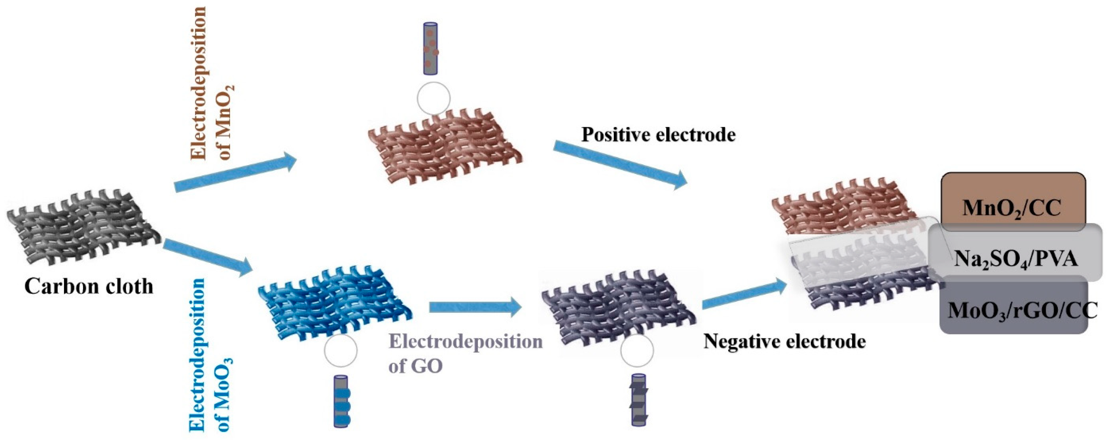
Figure 2.
The SEM images in different magnification for CC (A, B), MoO3/CC (C, D), MoO3/rGO/CC (E, F).
Figure 2.
The SEM images in different magnification for CC (A, B), MoO3/CC (C, D), MoO3/rGO/CC (E, F).
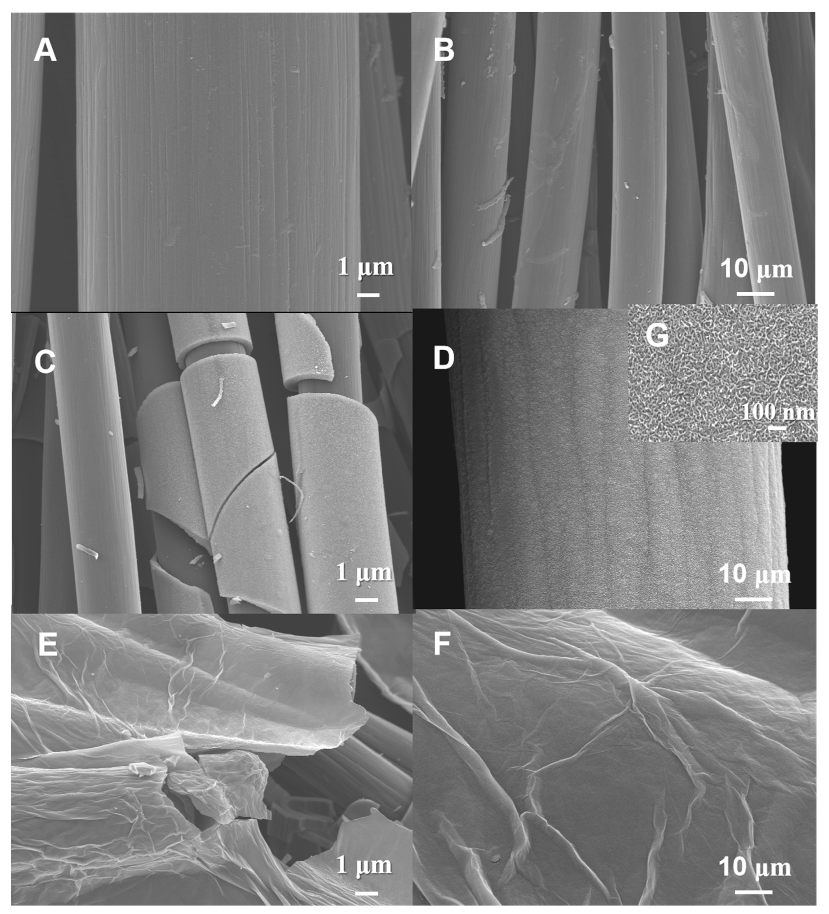
Figure 3.
The XRD patterns of CC, MnO2/CC, MoO3/CC and MoO3/rGO/CC (A), the magnified XRD patterns for MoO3/CC and MoO3/rGO/CC in the range of 10-50 ° (B).
Figure 3.
The XRD patterns of CC, MnO2/CC, MoO3/CC and MoO3/rGO/CC (A), the magnified XRD patterns for MoO3/CC and MoO3/rGO/CC in the range of 10-50 ° (B).
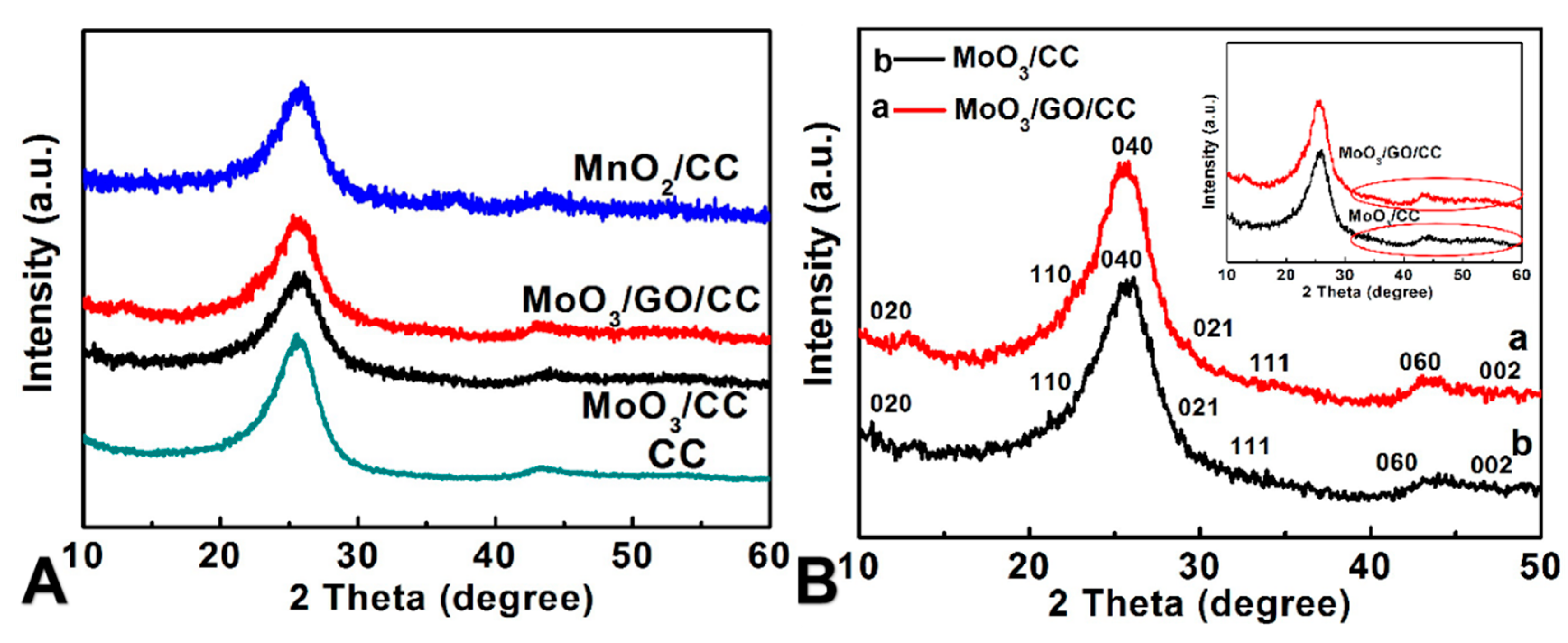
Figure 4.
(A) The whole XPS spectra for MnO2/CC (a), MoO3/CC (b), MoO3/rGO/CC (c) and CC (d), (B) the high-resolution XPS for Mn2p in MnO2/CC, (C) the C1s XPS for MnO2/CC, (D) the high-resolution XPS for Mo3d in MoO3/rGO/CC, (E) the C1s XPS and (F) N1s XPS for MoO3/rGO/CC.
Figure 4.
(A) The whole XPS spectra for MnO2/CC (a), MoO3/CC (b), MoO3/rGO/CC (c) and CC (d), (B) the high-resolution XPS for Mn2p in MnO2/CC, (C) the C1s XPS for MnO2/CC, (D) the high-resolution XPS for Mo3d in MoO3/rGO/CC, (E) the C1s XPS and (F) N1s XPS for MoO3/rGO/CC.
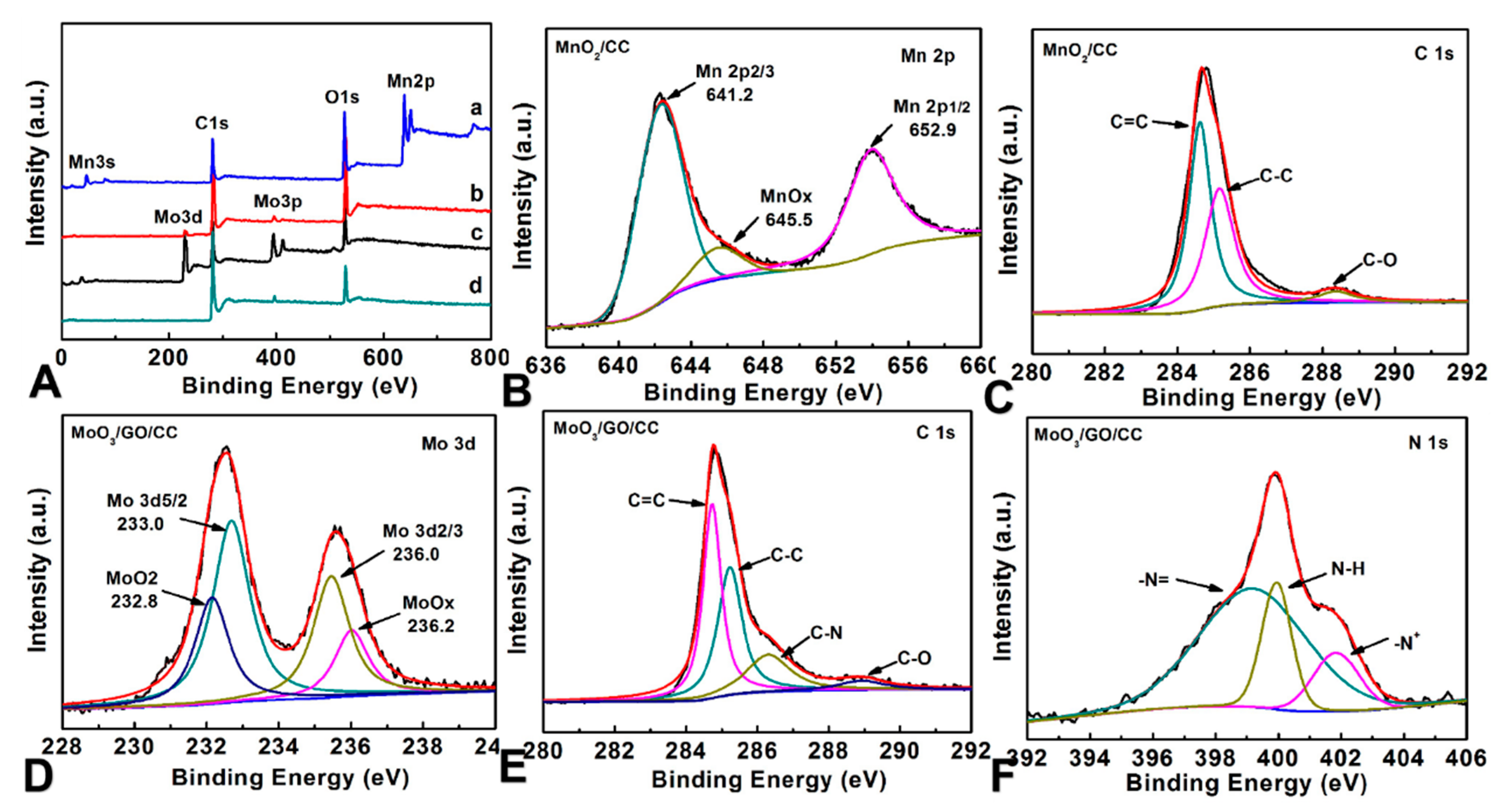
Figure 5.
Electrochemical behaviors of MoO3/rGO/CC electrode: (A) CV curves of CC, MoO3/CC and MoO3/rGO/CC, (B) CV curves for the MoO3/rGO/CC electrode at different scan rates, (C) the plot of the Cm values versus scan rate for MoO3/rGO/CC, (D) GCD curves of the MoO3/rGO/CC electrode at different current densities (a, b, c, d, e, f and g represent GCD curves with current density of 1-7 mA cm-2 respectively), (E) EIS spectra for the MoO3/rGO/CC electrode, (F) the plot of capacitance versus the cyclic number for MoO3/rGO/CC. Electrolyte is 0.5 mol L-1 Na2SO4 aqueous solution.

Figure 6.
(A) CV curves for MnO2/CC at different scan rates (a-g represent scan rates of 5, 10, 20, 40, 60, 80 and 100 mV s-1, respectively), (B) the plot of Cm of MnO2/CC versus the scan rates, (C) the CV curves of the positive and negative electrodes in three-electrode system at a scan rate of 20 mV s-1, (D) the FASC’s CV curves recorded at various potential difference windows at 20 mV s-1 (a, b, c, and d represent of 0-1.4, 1.6, 1.8 and 2.0 V respectively), (E) the FASC’s CV curves recorded at different scan rates (a-g represent scan rates of 2, 5, 10, 20, 50, 80 and 100 mV s-1, respectively), (F) the plot of the FASC’s Cm based on active material versus scan rates.
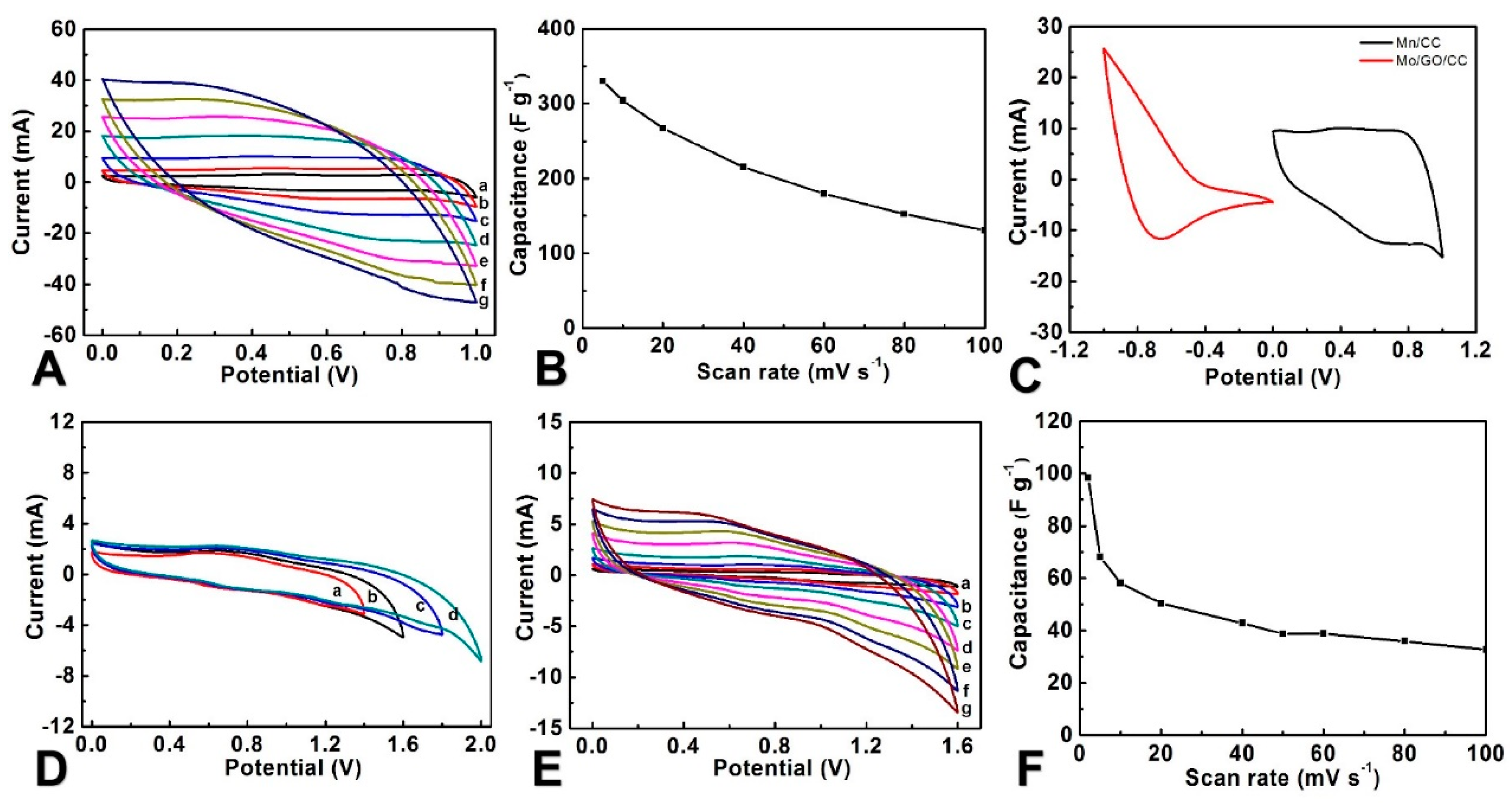
Figure 7.
(A) GCD curves of ASC recorded at different current densities (a-g represent current densities of 1.0, 2.0, 3.0, 4.0, 7.0, 10.0 and 12.0 mA cm-2), (B) the plot of specific capacitances versus current densities, (C) Nyquist plots for the ASC of MoO3/rGO/CC//MnO2/CC, (H) the plot of the capacitance of ASC versus the cyclic number.
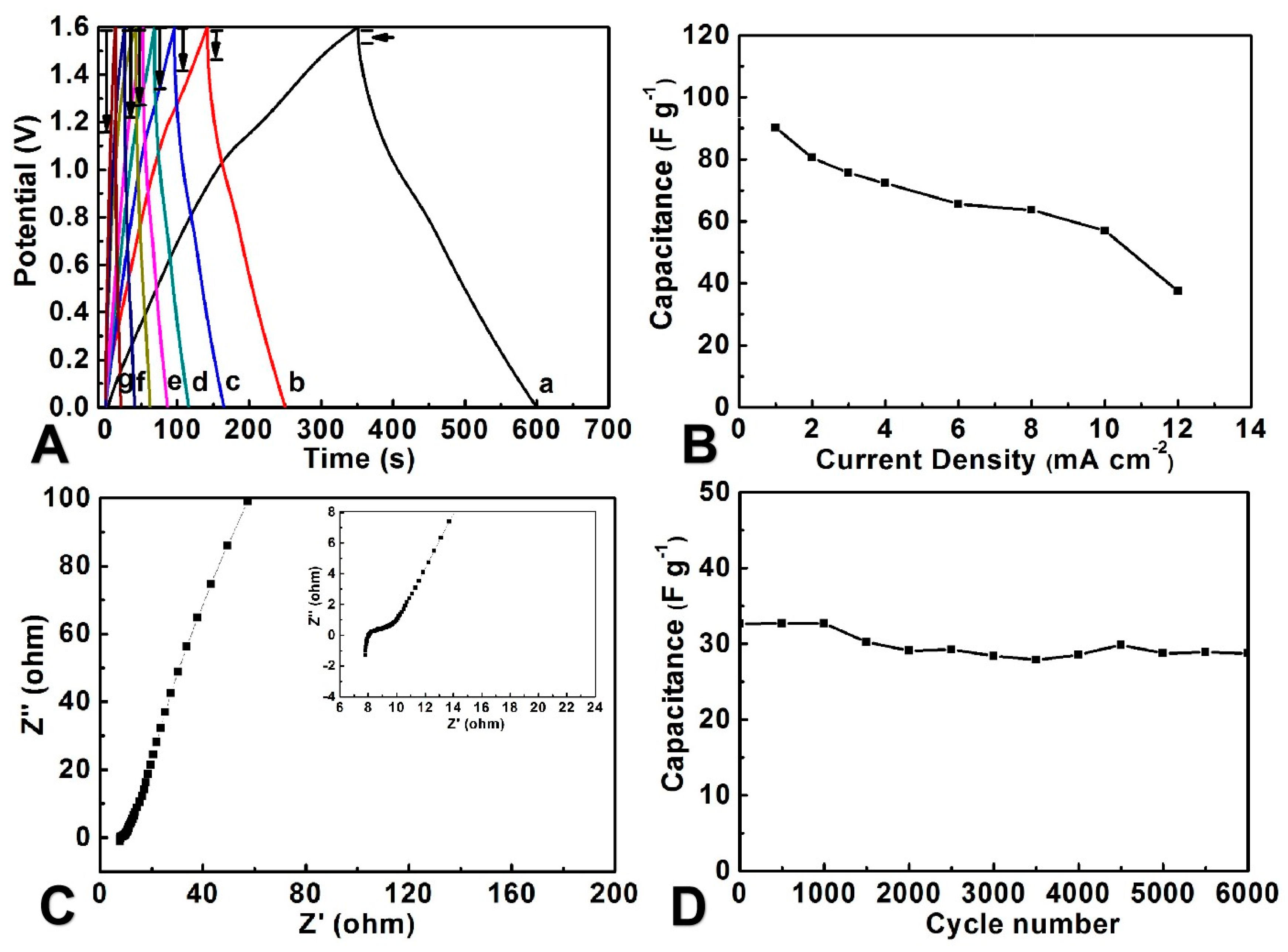
Figure 8.
(A) the Ragone plots for ASC of MoO3/rGO/CC//MnO2/CC and some other devices from previous literature for comparison [57,58,59,60,61,62,63,64], (B) the photograph of a LED lighted by two cells connected in series.
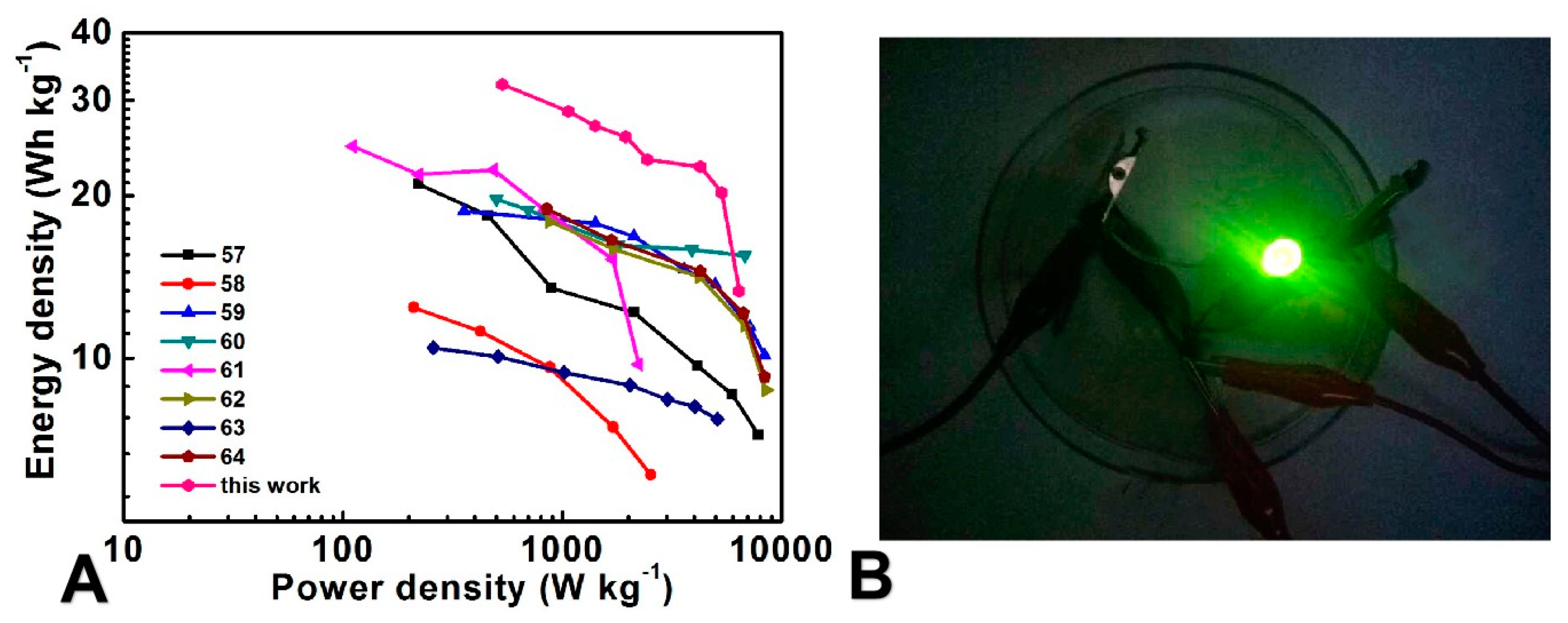

Table 1.
Comparison of the energy density and cyclic stability of the ASCs.
| Electrode materials | Electrolyte | Energy density (Wh kg-1) |
Stability (capacitance retention %, cycles) |
Ref. |
| MoO3-PPy//CNTs-MnO2 | Na2SO4/PVA gel | 21.0 | 76.0, 10000 cycles | [57] |
| MnO2@PEDOT//PEDOT | LiClO4/PMMA gel | 9.8 | 86.0, 1250 cycles | [58] |
|
Fe3O4 embedded in Carbon nanosheet//porous carbon |
KOH/PVA gel | 18.3 | 70.8, 5000 cycles | [59] |
| Graphene (IL-CMG) //RuO2-IL-CMG | H2SO4/PVA gel | 19.7 | 95.0, 2000 cycles | [60] |
| CNTs/MnO2//CNTs/PANI | Na2SO4/PVP gel | 24.8 | - | [61] |
|
Co3O4 nanowires/Ni-foam //carbon aerogel |
KOH/PVA gel | 17.9 | - | [62] |
| Mn3O4 nanoparticle/graphene //CNT/graphene | KCl/PVA gel | 32.7 | 86.0, 10000 cycles | [63] |
| Graphene/Ni(OH)2// graphene/CNT | KOH/PVA gel | 18 | - | [64] |
| MoO3/rGO/CC//MnO2/CC | Na2SO4/PVA gel | 32.1 | 88.1, 6000 cycles | This work |
Disclaimer/Publisher’s Note: The statements, opinions and data contained in all publications are solely those of the individual author(s) and contributor(s) and not of MDPI and/or the editor(s). MDPI and/or the editor(s) disclaim responsibility for any injury to people or property resulting from any ideas, methods, instructions or products referred to in the content. |
© 2024 by the authors. Licensee MDPI, Basel, Switzerland. This article is an open access article distributed under the terms and conditions of the Creative Commons Attribution (CC BY) license (http://creativecommons.org/licenses/by/4.0/).
Copyright: This open access article is published under a Creative Commons CC BY 4.0 license, which permit the free download, distribution, and reuse, provided that the author and preprint are cited in any reuse.


