Submitted:
28 April 2024
Posted:
29 April 2024
You are already at the latest version
Abstract
Wind energy is a kind of renewable energy with great potential for development. This study mainly investigated the application of shock waves generated by high-pressure gases (wind energy) for generating energy. In this study, we designed a new supersonic shock wave generator that can be reused without disassembling and assembling bolts and developed a supersonic shock wave monitoring system. This system monitored the velocity of the generated shock waves, which was Mach 3-5, and the output pressure was more than 100 times higher than the input pressure of the shock wave generator tank.Then, we developed a power generation system driven by supersonic shock waves based on the characteristics of the new shock wave generator, which can generate high-pressure and high-speed blast waves and can be reused. The shock wave generator can repeatedly generate high-pressure waves to drive the Tesla turbine and then the magnetic energy generator for power generation. We established a complete control process for power generation driven by shock waves by controlling the valve stem. The system can detect the tank pressure, output pressure, gas flow, rotation speed, voltage, and current during the control process for the performance analysis of power generation.
Keywords:
renewable energy
; high-pressure gas
; supersonic shock wave
; shock wave monitoring system
; power generation system
; automatic control process
; power efficiency analysis.
1. Introduction
The current approach to utilizing wind energy drives power generators by rotating wind turbines. The entire mechanical-electric facilities to match the generated electricity to the power grid or meet the power supply specifications of existing tools is very complicated [1,2]. As for existing wind generation facilities, giant windmills capture wind energy directly but represent only a tiny proportion of the total cost. The wind is free, but wind power generation is more expensive than thermal power generation. That is why countries tend to build larger and larger wind turbines [3,4,5]. Large wind turbines can reduce the unit cost of mechanical and electrical facilities but cause many other problems. For example, the wind energy conversion efficiency of large wind turbines is low because the difference between wind farms caused by large blade spans makes it challenging to optimize blade design; in addition, it is difficult to popularize wind energy because of the stringent conditions to locate large wind turbines.
Wind turbine blades are critical components in wind power generation; long blades lead to great twisting forces and high-power generation; thus, it is essential to develop large wind turbines with high power and long blades [5,7]. On the other hand, the longer the blades of a wind generator are, the higher it will be and the more space it will take up. According to the American Wind Energy Association, from 2000 to 2018, the average height of grid wind generators in the United States significantly increased from 58 m to 88 m, and the average blade diameter increased from 48 m to 116 m [6,7].
From the perspective of fluid energy, with current technologies, it is much easier to store high-pressure gases than high-temperature heat because its energy supplements very quickly, unlike batteries that take a long time to recharge. Moreover, high-pressure gases are easy to store and not easy to escape, so it is a good option for short-term (compared with chemical energy) energy storage. It is also challenging to convert compressed high-pressure gases into mechanical energy even with compressed high-pressure gases. For example, high-pressure molecules in internal combustion engines move in all directions but not just toward pistons, losing a lot of energy as heat energy. However, if low-pressure zones are deliberately created in front of high-pressure gases to guide all the molecules in that direction, it is called a shock wave [8,9]. Shock waves propagating in steady flows are usually generated at gas interfaces with differential pressure, such as shock tubes and explosion shock waves [10,11]. Studies on detonation waves generated by explosions have been conducted for more than half a century, including shock wave reflection, diffraction, the interaction between shock waves, and the interaction between shock waves and vortices[12,13,14]; these are essential bases for safety assessment and disaster prediction techniques in military and industry [15,16,17,18].
The shock wave is a supersonic shock wave when its speed exceeds Mach 1 (the speed of sound, about 340.3 m/s). Supersonic fluids have been applied in missiles, supersonic vehicles, space rockets, and operations or experimental research of high-speed vacuum flow. Various research institutions and industries are currently experimenting with supersonic fluid by using the shock waves generated by the intense compression of fluid between high-pressure and low-pressure zones. As for the design of existing devices used to generate supersonic shock waves, firing pins are mainly used to impact the metal partition (a thin aluminum sheet) between high-pressure and low-pressure zones to rupture them and create gaps or, the difference between high and low pressures is used to rupture a metal partition and create gaps so that a large amount of high-pressure gases can rush out of the gap to generate shock waves [19]. Figure 1 shows the structure of a shock wave generator that uses a striker to break a metal partition. Figure 2(a) shows a metal partition with a score in the middle. Figure 2(b) shows a metal partition broken by impact.
This supersonic shock wave generator works as follows: (1) when the high-pressure gases enter the front and rear sealed parts, due to their equal stressed area and acting force, the balanced valve stem creates static balance, which can effectively prevent the high-pressure gas from flowing into the homogeneous jet nozzle and shock tube (Figure 4(a)); (2) the balanced valve stem is driven to move backward, and the high-pressure gas in the gas storage space is rushed into the homogeneous jet nozzle and shock tube to cause shock waves (Figure 4(b) and Figure 4(c)); (3) when it works again, the balanced valve stem is just driven to move forward, so that the inlet of the high-pressure storage tank is precisely between the front and rear sealed parts of the balanced valve stem, then high-pressure gases can be input again to prepare to generate shock waves (as shown in Figure 4(a)).
In this study, we first designed a new supersonic shock wave generator structure to solve the existing problems in devices generating supersonic shock waves. Then, we developed a shock wave monitoring system to monitor the speed and pressure of the generated supersonic shock waves and verified the efficiency of repeated operation. Finally, this paper also presents the applications of the power generation system with supersonic shock waves as the aerodynamic source using the characteristics of the new shock wave generator, which can recurrently generate supersonic shock waves. We have developed an experimental system for supersonic shock wave-driven power generation, which can monitor and analyze power generation efficiency through automatic control and automatic measurement of the shock wave-driven power generation process.
2. Design of a New Shock Wave Generator
This study proposed a new supersonic shock wave generator [20] comprising a high-pressure storage tank and a balanced valve stem (as shown in Figure 3). Gas storage space was arranged on the outer ring inside the high-pressure storage tank and is joined with a high-pressure gas inlet unit by a pin. An inner cylinder is set in the center of the gas storage tank to connect with the outside world, and there is an inlet in front of the inner cylinder to connect with the gas storage space. A homogeneous jet nozzle is arranged at the front end of the high-pressure storage tank, and the front end of the nozzle is joined with a shock tube by a pin. The balanced valve stem is in the inner cylinder of the high-pressure storage tank, with a front and rear sealed part. The rear end is jointed with a stem driving device by a pin, which can drive the valve stem forward and backward in the inner cylinder by gas pressure.
This supersonic shock wave generator works as follows: (1) when the high-pressure gases enter the front and rear sealed parts, due to their equal stressed area and acting force, the balanced valve stem creates static balance, which can effectively prevent the high-pressure gas from flowing into the homogeneous jet nozzle and shock tube (Figure 4(a)); (2) the balanced valve stem is driven to move backward, and the high-pressure gas in the gas storage space is rushed into the homogeneous jet nozzle and shock tube to cause shock waves (Figure 4(b) and Figure 4(c)); (3) when it works again, the balanced valve stem is just driven to move forward, so that the inlet of the high-pressure storage tank is precisely between the front and rear sealed parts of the balanced valve stem, then high-pressure gases can be input again to prepare to generate shock waves (as shown in Figure 4(a)).
Figure 4.
A schema presenting the working of the supersonic shock wave generator. (a) The gas storage space is filled with high-pressure gases to make the balanced valve stem static and balanced; (b) The balanced valve stem moves backward to allow gas circulation between the gas storage space and jet nozzle; (c) The high-pressure gases are rushed into the homogeneous jet nozzle and shock tube to generate shock waves.
This shock wave generator may have the following advantages: (1) there is no need to notch the metal partition and to disassemble screw locks and a large number of joint bolts, which is easy and can reduce the labor cost; (2) the shock wave generation process needs no manual intervention, which can reduce the experimental failure rate and improve the shock wave generation efficiency; (3) no foreign matters and debris are rushed into the shock tube with airflow, which can improve the safety of the operator and reduce the need for equipment maintenance; and (4) after shock waves are generated, as long as the high-pressure storage tank is filled again, the generator can generate shock waves again. Hence, this generator makes supersonic shock wave generation experiments repeated dozens to hundreds of times each day and helps to design the automatic control architecture of the continuous shock wave generator, for example, the application in the power generation systems driven by supersonic shock waves.
3. Supersonic Shock Wave Monitoring
This section may be divided by subheadings. It should provide a concise and precise description of the experimental results, their interpretation, as well as the experimental conclusions that can be drawn.
3.1. Monitoring System Architecture
To verify the function and efficiency of the new shock wave generator, a supersonic shock wave monitoring system was developed in this study to monitor the speed and pressure of the generated shock waves. Figure 5 shows the shock wave monitoring system architecture. The black line represents the gas, the red dotted line represents the signal, and the blue line represents the fluid. The functions of all components in the system architecture are described as follows:
- (1)
- Shock wave generator: it is a device used to generate supersonic shock waves.
- (2)
- Activation control valve: it is controlled by the monitoring host and is used to activate the shock wave generator to generate supersonic shock waves.
- (3)
- Shock tube: it is a cylindrical steel tube with water as the carrier, and the shock waves generated enter the steel tube to move and reflect quickly.
- (4)
- High-pressure gas supply unit: it is used to generate high-pressure gases and provide gases to the shock wave generator to generate shock waves. It can be an air compressor or a high-pressure gas cylinder.
- (5)
- Inlet valve: it is used to control high-pressure gases entering the gas storage tank of the shock wave generator.
- (6)
- Input pressure gauge: it is used to monitor the pressure of the gases entering the gas storage tank of the shock wave generator.
- (7)
- Output pressure gauge: it is a mechanical pressure gauge with residual pressure used to monitor and display the maximum pressure in the shock tube.
- (8)
- Front-end pressure sensor: it is a high-pressure and high-speed pressure sensor installed at the front end of the shock tube.
- (9)
- Rear-end pressure sensor: it is also a high-pressure and high-speed pressure sensor installed at the rear end of the shock tube.
- (10)
- Water inlet valve: it is used to assess and control whether to input water into the shock tube and is installed below the shock tube.
- (11)
- Water source: it provides water for the shock tube and is used as a water bucket or tap.
- (12)
- Exhaust drainage valve: it is a control valve installed at the top of the shock tube for exhaust or drainage, so the shock tube is filled with water when water flows out of the valve.
- (13)
- Drainage tank: it is used to receive water or gases from the exhaust drainage valve.
- (14)
- Drainage valve: it is a control valve for removing residual water from the shock tube.
- (15)
- Signal transformation unit: it is a data acquisition and control card for acquiring pressure signals measured by the front-end and rear-end pressure sensors and then transmitting them to the monitoring host for processing. It also transmits the command of the monitoring host to the activation control valve to activate the shock wave generator to generate supersonic shock waves.
- (16)
- Monitoring host: it is a personal computer that executes LabVIEW monitoring software. Through the signal transformation unit, the monitoring host commands the activation control valve to activate the shock wave generator to generate supersonic shock waves. On the other hand, it synchronously acquires the pressure signals measured by the front-end and rear-end pressure sensors. It then calculates and analyzes supersonic shock waves' movement speed and output pressure in the shock tube.
3.2. Numerical Simulation of the Shock Wave Monitoring
For the numerical simulation of supersonic, high-temperature, and high-pressure flow fields in a long cylindrical shock tube [21], this study uses a multi-block grid approach, using CFD (computational fluid dynamics) code based on the control volume method and the preconditioning method for solving Navier-Stokes equations to model compressible and incompressible coupling problems. We define the inviscid flux vector in the standard conservation form as follows:
where ρ is the density, is the velocity vector, vx, vy, and vz are the velocity components in the x, y, and z directions respectively, p is the pressure, E is the total energy per unit mass, and the relationship between E and the total enthalpy H is H = E – p/ρ, where H = CpT + V2/2, Cp is the constant pressure specific heat and T is the temperature. This system is closed by the equation of state, which usually has the form ρ=ρ(p, T). The low diffusion flux splitting method of AUSM+ is used here [22], then the inviscid interface flux Fi+1/2 in the x direction can be decomposed into the sum of the convection contribution and the pressure contribution , where the subscript 1/2 represents the center of the grid, and the convection term and the pressure term can be defined as follows:
In the convection term , if the interface mass flux (ρvx)1/2 is non-negative, then the state i is selected for the column vector (1, vx, vy, vz, H)T; if ( ρvx )1/2 is negative, then state i+1 is selected. The interface quantities (ρvx)1/2 and p1/2 are defined as follows:
Among them, a1/2 is the interface sound speed, Mi is the MACH number, Mi = vxi / a1/2, and and are defined as follows:
and in equation (4) are both fifth-degree polynomials of M, and their definitions are as follows:
and in equation (5) are both fourth-degree polynomials of M, and their definitions are as follows:
Next, we use the following Navier-Stokes equations as governing equations:
where Ω is an arbitrary control volume, is the surface area, W is the dependent vector of conservative variables, is the viscous flux vector in the standard conservation form, W and are defined as follows:
In the preconditioning method, we convert the governing equations defined by the conservative variable W into the form defined by the primitive variable Q = (p, vx, vy, vz, T)T, as follows:
where Г is the preconditioning matrix, which is based on the matrix proposed by Choi and Merkle [23] and further expanded by Weiss and Smith [24]. Г is defined as follows:
where R is the gas constant, and 𝜣 and H are defined as follows:
where |V| is the local velocity, |V∞| is the fixed reference velocity, a is the speed of sound, and K is a constant. The Weiss-Smith preconditioner is formed by adding the vector 𝜣[1, vx, vy, vz, T]T to the Jacobian matrix ∂W/∂Q, where W is a vector of conservative variables. In this study, K is fixed at 0.25, and the eigenvalues of Г-1A (A=∂F/∂W) are vx, vx'±a', where vx is the velocity component in the x direction, and
3.3. Development of the Shock Wave Monitoring System
Figure 6 shows the entity of a supersonic shock wave monitoring system prepared according to the system architecture in Figure 5. In the entity monitoring system, we used an air compressor as the high-pressure gas supply unit and set the gas pressure at 5 kg. Moreover, Model 113B23 pressure sensors that can measure gas with high pressure and high speed are adopted as the front-end and rear-end pressure sensors [25], with the resonant frequency ≥ 500 kHz. The pressure sensing (Pmin ~ Pmax) ranging from 0 psi to 15000 psi (equivalent to 0 kg/cm2 to 1054 kg/cm2), the output voltage (Vmin ~ Vmax) of the two pressure sensors ranging from 0 V to 7.5 V, and the distance (Δd) between the two pressure sensors is 35 cm. The signal transformation unit uses NI USB-6341 X Series data acquisition and control card [26], with a sampling rate of 500 KS/s and input-output channels (pins) including 16 AIs, 24 DIOs, and 2 AOs. In this monitoring system, two analog input channels (AI0 and AI1) are used to acquire the pressure signals measured by the front-end and rear-end pressure sensors, respectively. A digital output channel (PA00) transmits DO commands to the activation control valve.
In this study, we used the LabVIEW graphical language [27,28,29] to develop the monitoring software for the shock wave monitoring system. Figure 7 shows the startup screen of the monitoring software.
The monitoring system's sample number and sampling rate are shown in the upper left of the screen. Function buttons such as "Activate," "Clear curves," "Read curves," and "End" are shown in the lower left of the screen. The "Activate" button activates the generation and monitors shock waves. The "Clear curves" button can clear the screen's pressure curve and measurement parameters. The "Read curves" button displays the pressure curve data saved previously. The final "End" button ends system execution.
In the middle of the screen is a pressure curve chart showing the measured pressure curves. There is an output data file path that users can set at the bottom center of the screen; a monitoring result display zone is located on the right side of the screen to display the monitored data and the calculated result of shock wave speed and shock wave pressure.
3.4. Experimental Analysis of Supersonic Shock Wave Monitoring
The shock wave monitoring results are shown in Figure 8, the upper left corner shows that the sample number ns of this monitoring system is 100000 points (Pt), and the sampling rate rs is 100000 Pt/sec, namely, the sampling time ts of each Pt is 1/100000 sec. Buffered sampling [26] was adopted in this study. At a sampling rate of 100000 points per sec, the pressure values of 100000 points measured at each end were collected (lasting for 1 sec) to draw the pressure curve.
The pressure curve chart in the middle of the screen shows two curves in blue and red. The blue curve represents the front-end pressure curve, while the red curve represents the rear-end pressure curve. The system automatically displays the pressure pulses with the maximum peak (namely, the first measured shock wave) in the center of the chart. In this chart, a blue (front-end) pressure pulse appears first, followed by a red (rear-end) pressure pulse (we can ignore noises with slight pressure), indicating that the shock wave first passes through the front-end pressure sensor and then the rear-end pressure sensor. After that, a red-pressure pulse follows another red-pressure pulse, giving rise to another blue-pressure pulse. This phenomenon indicates that after passing through the rear-end pressure sensor for the first time, the shock wave reaches the bottom of the shock tube and reflects; the reflected shock wave first passes through the rear-end pressure sensor and then the front-end pressure sensor.
The measurements and calculated parameters in the monitoring result display zone on the right side of Figure 11 are analyzed from top to bottom as follows:
- (1)
- Maximum voltage measured: the maximum peak voltage of the pressure pulse measured appears at the peak, where "Ch1 Max" represents the maximum voltage (vfmax) of the front-end pressure curve (channel 1), and "Ch2 Max" represents the maximum voltage (vrmax) of the rear-end pressure curve (channel 2). At this point, vfmax = 6.756V and vrmax = 6.728V.
- (2)
- Location with the maximum pressure: "Ch1 Max Pos" represents the location (lfmax) with the maximum value of the front-end pressure curve, and "Ch2 Max Pos" represents the location (lrmax) with the maximum value of the rear-end pressure curve. At this point, lfmax = 8959 Pt, and lrmax = 8983 Pt.
- (3)
-
Distance and time differences between both ends: the distance Δd between the front-end pressure sensor and the rear-end pressure sensor was 0.35 m, and the system calculates the time difference Δt of two pressure pulses based on the difference between the rear end and the front-end in positions of the maximum pressure, namely,Therefore, Δt = (8983 - 8959) × 0.00001 = 24 × 0.00001 = 0.00024 sec, where ts is the time of each sampling (0.00001 sec).Δt = (lrmax - lfmax) × ts
- (4)
- Shock wave velocity and Mach: the shock wave velocity in the x direction can be calculated by dividing the distance between the front end and rear end by the time difference between the shock wave passing through the front-end and rear-end sensors, namely, shock wave velocity vx (m/sec) was calculated as follows:Therefore, vx = 0.35 m / 0.00024 sec = 1458.33 m/sec. In addition, because Mach 1 (Ma) was about 340.3 m/sec, the shock wave velocity Mx in Mach was calculated as follows:vx = Δd/ΔtMx = vx / 340.3 = 1458.33 / 340.3 = 4.29 (Mach)
- (5)
-
Input pressure and output pressure: we fixed the input pressure pin at 5 kg/cm2 in the shock wave monitoring. However, the maximum peak voltage of the pressure pulse measured appears at the peak. Therefore, the output pressure pout of the shock wave was calculated from the maximum peak voltage (Vfpeak) of the front-end pressure pulse or the maximum peak voltage (Vrpeak) of the rear-end pressure pulse. The equation is as follows:Vpeak = max(Vfpeak, Vrpeak)Since Vfpeak = 6.756V and Vrpeak = 6.728V, so Vpeak = 6.756V. And Vmin = 0V, Vmax = 7.5V, Pmin = 0 kg/cm2 and Pmax = 1054 kg/cm2, therefore the calculated output pressure pout = (6.756V / 7.5V) × 1054 kg/cm2 = 945.51 kg/cm2. We can compare the output pressure of the shock wave measured by this monitoring system with the value measured by the magnetic output pressure gauge on the shock tube for verification. The data measured by the output pressure gauge on the shock tube are shown in Figure 9. The values shown by the red pointer in Figure 9(b) were all about 945 kg/cm2, verifying the pressure measured by this monitoring system.
- (6)
- Magnification ratio: the pressure magnification ratio rp is the ratio of the output pressure pout to the input pressure pin, namelyrp = pout / pin
Therefore, pressure magnification ratio rp = 945.51 / 5 = 188.3 (times).
In this study, 20 shock wave monitoring experiments were conducted. We fixed the input pressure at 5 kg, and the system calculated the time difference (Δt) between the front and rear ends, velocity (vx), Mach (Mx), output pressure (pout), and magnification ratio (rp) in each experiment. The statistical results are shown in Table 1. The sequence numbers of experiments are not arranged in order in this statistical table because we rearranged the statistical results from small to large according to the speed. According to Table 1, for the 20 shock wave monitoring experiments, the average speed was 1480.33 m/s and equivalent to Mach 4.36, the maximum average pressure was 943.31 kg/cm2, and the average magnification ratio was 188.7 times. On the other hand, the table also shows that the shock wave speed was proportional to the maximum pressure generated; the higher the speed, the higher the pressure will be.
4. Design of a Power Generation System driven by Supersonic Shock Waves
4.1. System design
We designed and developed a power generation system with supersonic shock waves as the aerodynamic source based on the developed shock wave generator. Figure 10 shows the architecture of the power generation system driven by supersonic shock waves.
The functions of the components in the system architecture in Figure 11 are described as below:
- (1)
- Shock wave generator: it comprises a high-pressure storage tank and a balanced valve stem. When the balanced valve stem moves backward and the gases in the high-pressure storage tank reach the set pressure, the generator can generate shock waves that rush out of the homogeneous jet nozzle.
- (2)
- Valve stem controller: it can drive the balanced valve stem of the shock wave generator forward and backward. When the balanced valve stem moves backward (ON), the generator generates a shock wave, and high-pressure gas rushes out to drive the Tesla turbine to rotate. When the balanced valve stem moves forward (OFF), the output of high-pressure gases stops.
- (3)
- Gas source: it is a high-pressure gas cylinder or an air compressor that provides high-pressure gases for the high-pressure storage tank of the shock wave generator.
- (4)
- Regulator: it can adjust the gas pressure output from the gas source.
- (5)
- Flow detector: it detects the gas flow fg delivered from the gas source to the high-pressure gas storage tank. The flow signals detected can be transmitted to the monitoring host through the signal transformation unit.
- (6)
- Tank pressure detector: it can detect the gas pressure pt in the high-pressure storage tank of the shock wave generator. The pressure signals detected can be transmitted to the monitoring host through the signal transformation unit.
- (7)
- Output pressure detector: it can detect the gas pressure po output from the shock wave generator. The pressure signals detected are transmitted to the monitoring host through the signal transformation unit.
- (8)
- Tesla turbine: the turbine can rotate through the impact of shock waves and high-pressure gas and can continue to rotate after the high-pressure gas stops through its energy storage inertia. The rotated turbine can rotate the rotating rod and then drive the magnetic energy generator to work.
- (9)
- Rotation speed detector: it can detect the rotation speed sr of the rotation rod. The speed signals detected are transmitted to the monitoring host through the signal transformation unit.
- (10)
- Magnetic energy generator: it comprises a rotating permanent magnet and a stationary coil. The rotating rod rotates to rotate the magnet to cut magnetic lines and generate power. According to the principle that magnet motors can rotate sustainably due to magnetic action, it can supplement the heat consumed by friction, increase the continuous high-speed magnet rotation time, and improve the power generation efficiency.
- (11)
- Power control unit: it can convert the alternating current generated by the magnetic energy generator into direct current and provide it to the power output unit.
- (12)
- Voltage detector: it can detect the voltage Vp of power generated by the magnetic energy generator. The voltage signals detected are transmitted to the monitoring host through the signal transformation unit.
- (13)
- Current detector: it can detect the current Ip of power generated by the magnetic energy generator. The current signals detected are transmitted to the monitoring host through the signal transformation unit.
- (14)
- Power output unit: it contains an energy storage battery and a load unit. The load unit is a light bulb box containing five parallel light bulbs. Users can turn each light bulb on or off. The power provided by the power control unit can charge the energy storage battery or directly supply the power required by the load unit.
- (15)
- Signal transformation unit: it is an Advantech USB-4711A multi-functional high-speed signal acquisition and control card [30]. It can transmit signals measured by the tank pressure detector, output pressure detector, rotation detector, and power control unit to the monitoring host for processing. It further transmits driving commands from the monitoring host to drive the valve stem controller.
- (16)
- Monitoring host: it is a personal computer that executes LabVIEW monitoring software. It receives the signals of tank pressure, output pressure, rotation speed, and power voltage. Then, it sends the control signals to drive the valve stem controller to carry out the control process of power generation driven by supersonic shock waves.
4.2. Shock waves-driven control process
In this study, we developed the automatic monitoring software in the LabVIEW graphical language [23,24,25] for the power generation system driven by supersonic shock waves. Figure 13 shows the control process of this software. The symbols used in this control process have the following meanings: (a) Ptmin: the lower threshold of pressure in a high-pressure storage tank; (b) Srmin: the lower threshold of rotation speed; (c) Td: the delay time for high-pressure gas output. The control process consists of four stages: setting, storage tank gas-filling, shock wave and gas output, and rotation speed detection, which includes seven steps. Step (1) is in the setting stage, steps (2) and (3) are in the storage tank gas-filling stage, steps (4) and (5) are in the shock wave and gases output stage, and steps (6) and (7) are in the rotation speed detecting stage. This control process automatically monitors the shock waves-driven power generation experiments [31,32].
4.3. Power generation experiments and analysis
Figure 14 shows the execution screen of the supersonic shock wave-driven power generation monitoring software. This monitoring software can execute the automatic control program shown in Figure 15. The control parameters set by the user are displayed in the upper left corner of the execution screen in Figure 16, such as the minimum tank pressure (Ptmin), minimum rotation speed (Srmin), and delay time (Td), where Ptmin = 3.5 kg/cm2, Srmin = 1200 rpm, Td = 2 Sec. The square light "Low pressure" on the left side of the screen indicates whether the tank pressure is too low (pt < Ptmin), the red light means too low, and the green light means sufficient; the square light "Low rotation" indicates whether the rotational speed is insufficient (sr < Srmin ). The circular light "Activation" represents the activation of shock wave output. The sampling rate, elapsed time, and number of data records are displayed at the bottom of the screen.
During the monitoring process of the shock-driven power generation, the system will automatically capture six measurement data, including the storage tank pressure pt, output pressure po, rotation speed sr, gas flow rate fg, voltage Vp, and current Ip, at a sampling rate of once every 0.2 seconds. The curves of these measurement data will be displayed in the six curve graphs in the center of the screen in Figure 17. From the comparison of the tank pressure pt curve and the output pressure po curve, we can see that the pt can be inflated to about 5 kg/cm2 ≥ Ptmin = 3.5 kg/cm2 each time (steps (2) and (3) in Figure 14). After the shock wave, po will first appear a steep wave (pulse), and then the output pressure of about 0.5 kg/cm2 will last for 2 (Td) seconds. During this time, pt will drop to a low point (steps (4) and (5)). At this time, if sr ≥ Srmin, wait for sr to drop. When sr < Srmin, inflate again and re-enter the next cycle (steps (6) and (7)). We can see from the speed curve in the screen that the system controls the speed sr of the connecting rod at around 1200 rpm (Srmin), and the speed sr determines the size of the output voltage Vp. When the monitoring process is completed, the system will automatically save the set parameters and all measured curve data to the file for subsequent power generation performance analysis.
Figure 15 shows a display screen of the results of a power generation monitoring experiment. This screen displays six curves from top to bottom; they are the curves of pressure (including yellow storage tank pressure pt and red output pressure po), gas flow rate fg, rotation speed sr, voltage Vp, current Ip, and power Ep, where Ep = Vp ∙ Ip. The X-axis of each graph is in the same time sequence. Users can simultaneously scroll the X-axis display range of the six graphs through the sliding bar on the upper right side of the screen to observe the power generation performance in each period.
We mark five time points A, B, C, D, and E on the X-axis of Figure 17. The A-B period is the power generation period when no load (0 bulbs) is turned on at the power output end, while the B-C, C-D and D-E periods are the power generation periods when 1, 2 and 3 light bulbs are turned on respectively. It can be seen from the Ip curve in the figure that the Ip and Ep in the A-B period (0 bulb) are both zero, while the Ip and Ep in the 1-bulb, 2-bulbs and 3-bulbs periods gradually increase, indicating that the greater the load (the greater the number of light bulbs), the larger both Ip and Ep.
Table 2 shows the average values of relevant monitoring data in each period, where fs-avg-k, rs-avg-k, fg-avg-k, Vp-avg-k, Ip-avg-k, and Ep-avg-k (k = 0, 1, 2, 3) are the average value of the shock frequency, rotation speed, flow, voltage, current and power in the period that k bulbs are opened. The statistical results in Table 2 show:
fs-avg-0 < fs-avg-1 < fs-avg-2 < fs-avg-3
rs-avg-0 > rs-avg-1 > rs-avg-2 > rs-avg-3
fg-avg-0 < fg-avg-1 < fg-avg-2 < fg-avg-3
Vp-avg-0 > Vp-avg-1 > Vp-avg-2 > Vp-avg-3
Ip-avg-0 < Ip-avg-1 < Ip-avg-2 < Ip-avg-3
Ep-avg-0 < Ep-avg-1 < Ep-avg-2 < Ep-avg-3
Based on the statistics of the above monitoring results, we can analyze the performance of this shock wave-driven power generation experiment as follows:
- (1)
- It can be seen from equation (7) that when the number of light bulbs that are turned on increases, the frequency of the generated shock waves also increases, which means that the more the load, the greater the aerodynamic force that needs to be supplied.
- (2)
- Equations (8) and (10) show that the load becomes larger when the number of bulbs increases. Although the rotation speed is still controlled near Srmin(1200 rpm), it still decreases slightly as the number of bulbs increases, so the output voltage also gradually decreases.
- (3)
- Equation (9) shows that when the number of bulbs increases, to maintain a fixed speed, more high-pressure gas needs to be consumed so that the flow rate will increase significantly, and the more bulbs, the higher the gas flow rate.
- (4)
- Equations (11) and (12) indicate that when the number of light bulbs increases, both Ip-avg and Ep-avg become larger. When users turn on a light bulb, its average load resistance Rl-avg-1 is calculated as follows:Rl-avg-1 = Vp-avg-1 / Ip-avg-1 = 26.79 / 0.05133 = 521.92Ω
- (5)
- When turning on 2 or 3 bulbs connected in parallel, if R1, R2, and R3 are bulb resistors, Rl2 and Rl3 represent the load resistance of 2 bulbs and 3 bulbs connected in parallel. We can express the load resistors Rl2 and Rl3 as expressions (13) and (14) (since R1=R2=R3):


The average load resistance Rl-avg-2 and Rl-avg-3 are calculated as follows:
Rl-avg-2 = Vp-avg-2 / Ip-avg-2 = 25.46 / 0.09863 = 258.14Ω ≈ Rl-avg-1 / 2 = 260.96Ω
Rl-avg-3 = Vp-avg-3 / Ip-avg-3 = 24.44 / 0.143260 = 170.60Ω ≈ Rl-avg-1 / 3 = 173.97Ω
This calculation result is consistent with the relationship between Equation (13) and Equation (14), showing that the average error of the monitoring results of this experiment is tiny.
5. Conclusions
In this paper, we propose the design of a new supersonic shock wave generator as a solution to the problems in traditional supersonic shock wave generators. The shock wave generator mainly comprises a high-pressure storage tank and a balanced valve stem. When the balanced valve stem is moved backward, a gas outlet is created on the high-pressure storage tank to allow a large amount of high-pressure gases to rush out rapidly to generate a shock wave. Then, the balanced valve stem is moved forward to close the gas outlet, and the high-pressure gases are inputted into the high-pressure storage tank once again. Therefore, the balanced valve stem can move backward again, generating another shock wave. Moreover, to verify the functions and efficiency of this new shock wave generator, a supersonic shock wave monitoring system was developed in this study to monitor the speed and pressure of the generated shock waves. The shock wave monitoring experiments by the system to verify that the new supersonic shock wave generator has the following characteristics: (1) saving workforce and material resources: thin aluminum sheets need not be used, so it is unnecessary to disassemble screw locks and a large number of joint bolts; (2) high security: the thin aluminum sheets need not be broken, which reduces risks for operators; (3) high operation efficiency: the shockwave generation efficiency is very high, for there is no need to replace thin aluminum sheets; (4) repeatable operation: as long as the high-pressure storage tank is re-filled with gases, it can generate supersonic shock waves repeatedly; (5) it can generate supersonic shock waves of Mach 3 to 4; and (6)it can generate high-pressure shock waves with a magnification ratio of 100 times.
On the other hand, this research further utilizes the characteristics of a new type of shock wave generator that can generate high-pressure shock waves and has repeatable operation to design a power generation system using supersonic shock waves as a source of aerodynamic force. We have developed a shock wave-driven power generation experimental system. This system can execute the control program of shock wave-driven power generation, repeatedly generating high-pressure shock waves to rotate the Tesla turbine and then drive the magnetic energy generator to generate electricity. In the shock wave-driven power generation experiment, we turned on different numbers of parallel lamp loads and automatically monitored and plotted 7 data curves. They are storage tank pressure pt, output pressure po, rotation speed sr, gas flow rate fg, voltage Vp, and current Ip and power Ep. Through observing and calculating these data curves, we can carry out the performance analysis of the shock wave-driven power generation experiment. The analysis results show that: 1. The output voltage Vp is proportional to the rotation speed sr, so controlling this sr can determine the Vp. 2. When there is no load (the number of bulbs is 0), the output current Ip and power Ep are zero. 3. The more light bulbs are turned on, the greater the Ip and Ep generated. 4. The more light bulbs are turned on, the greater the required gas flow fg, and the higher the frequency fs of the shock wave. 5. The voltage Vp, current Ip, and resistance Rl monitored and calculated by the power generation laboratory can all comply with the relevant circuit analysis laws for different numbers of parallel light bulb loads.
Through the results of this shock wave-driven power generation experiment, this study can verify the feasibility of using supersonic shock waves as a source of aerodynamic force for the power generation system.
6. Patents
- (1)
- Hu, M. S. and Su, R. H., Generating device for supersonic shock waves (R.O.C. New Patent No. M553377).
- (2)
- Hu, M. S., Su, R. H., Hsu, U. K. and Tai, C. H., Power generation system driven by dual-cycle supersonic shock waves (R.O.C. Invention Patent No. I700432).
- (3)
- Su, R. H., Chung, L. Y., Hu, M. S. and Jia, Z. M., Geothermal well productivity enhancement method and system (R.O.C. Invention Patent No. I601874).
- (4)
- Hu, M. S. and Su, Y. L.,Pipeline obstruction clearing device using supersonic shock waves (R.O.C. New Patent No. M646343).
- (5)
- Hu, M. S., Su, Y. L. and Chen Yang, Z. G., Lightweight supersonic shock wave hard ground excavator (R.O.C. New Patent No. M615448).
- (6)
- Hu, M. S., Su, Y. L., Portable supersonic shock wave rock crusher, (R.O.C. New Patent No. M608193).
- (7)
- Hu, M. S., Su, Y. L.,Tsai , S. H. and Hsu, U. K., Supersonic shock wave soil loosening and hole fertilization device (R.O.C. New Patent No. M646343).
Author Contributions
Conceptualization, Hu, M. S.; methodology, Hu, M. S. and Hsu, U. K.; software, Hu, M. S. and Hsu, U. K.; validation, Hu, M. S. and Hsu, U. K.; formal analysis, Hu, M. S.; investigation, Hu, M. S.; resources, Hu, M. S.; data curation, Hu, M. S and Hsu, U. K..; writing—original draft preparation, Hu, M. S.; writing—review and editing, Hu, M. S. and Hsu, U. K.; visualization, Hu, M. S.; supervision, Hu, M. S.; project administration, Hu, M. S.; funding acquisition, Hu, M. S. All authors have read and agreed to the published version of the manuscript.
Funding
This research was funded by R. O. C. Ministry of National Defense’s 2021 military product research and development plan, the second phase of the industry-university cooperation research plan of the Ministry of Science and Technology of R. O. C. in 2020 (MOST 109-2622-E-344-001) and National Science Council of R. O. C. 2022 Energy Science and Technology Research Plan (NSTC 111-2221-E-344-001).
Institutional Review Board Statement
This study did not require ethical approval and did not involve humans or animals.
Informed Consent Statement
Not applicable.
Acknowledgments
This study acknowledges Mr. Su You-Lin of Jiurong Industrial Co., Ltd. for hardware technical support.
Conflicts of Interest
The authors declare no conflicts of interest.
References
- Liu, W.K. , Chang, C.E., Lee, E.F. and Yue, P. Wind Energy and Wind Power Technology, Wu Nan Books, 2009.
- Bensalah, A. , Benhamida, M.A., Barakat, G. and Amara, Y. Large wind turbine generators: State-of-the-art review, IEEE Xplore: 25 Oct. 2018, ISSN:2381-4802.
- Gimenez, R.B. , Hsieh, H.Y. and Lin, F.J. Development Trend of Large Wind Turbine Technology, Department of Electrical Engineering, National Central University, 2013.
- Green Trade Project Office, Current Situation and Future Prospect of Taiwan’s Wind Power Industry, Industrial Technology Research Institute IEK, 2018/02.
- Wang, R.H. Wind Power Promotion Policies of Major Countries and Wind Power Market and Industry Trend Analysis in 2017, Achievements Report on Promotion of Thousands of Onshore and Offshore Wind Turbines and Key Technology Development Plan of the Energy Technology Development Program by the Ministry of Economic Affairs (2/3), Industrial Technology Research Institute, April 28, 2017.
- Gerdes, J. Kissing the Sky: The Pros and Cons of Ultra-Tall Wind Turbine Towers, A Wood Mackenzie Business, Sep. 05, 2019.
- Yeh, T.H. and Wang, L. A Study on Generator Capacity for Wind Turbines Under Various Tower Heights and Rated Wind Speeds Using Weibull Distribution, IEEE Transactions on Energy Conversion 2008, 23, 592–602. [Google Scholar]
- Ben-Dor, G. Shockwave Reflections Phenomena, Springer-Verlag, New York, N.Y.,1991.
- Smoller, J. Shock Waves and Reaction—Diffusion Equations, Springer-Verlag, New York, Heidelberg Berlin, 1983, ISBN 3-540-90752-1.
- Von, N.J. Oblique Reflection of Shock, Explosion Research Reports 12, Washington D. C., 1943.
- Tang, M.J. and Baker, Q. A., A New Set of Blast Curves from Vapor Cloud Explosion, Process Safety Progress. Winter 1999, 18, 235–240. [Google Scholar]
- Igra, O. , Hu, G. , Falcovitz, J. and Heilig, W., Blast Wave Reflection from Wedges, Journal of Fluids Engineering 2003, 125, 510–519. [Google Scholar]
- Mazarak, O. , Martins C. , and Amanatides, J. Animating Exploding Objects, Graphics Interface 1999, 99, 211–218. [Google Scholar]
- Yngve, G.D. , O’Brien, J.F. and Hodgins, J.K. Animating Explosions, Proceedings of SIGGRAPH2000, August 2000, p. 29-36.
- Tai, C.H. , Hsu, U. K. and Lai, C.C. Design and Simulation of an Opposed-piston Engine Worked by the Resonant and Focusing of the Shock Wave, International Journal of Mechanical and Production Engineering 2017, 5, 7–11. [Google Scholar]
- Shih, C.H. , Tsai, Y.Y., Tai, C.H. and Hsu, U.K. Numerical Studies on the Explosion Shock Waves of a Large Truck Tires in Airport. 2020AASRC, Hsinchu, Taiwan, Nov. 2020.
- Fadai, N.T. and Simpson, M. J. New travelling wave solutions of the Porous–Fisher model with a moving boundary. J. Phys. A Math. Theor. 2020, 53, 095601. [Google Scholar] [CrossRef]
- Li, Y. , Heijster, P.V., Simpson, M.J. and Wechselberger, M. Shock-fronted travelling waves in a reaction-diffusion model with nonlinear forward-backward-forward diffusion, Physica D 423, 2021, Elsevier B.V.
- Wen, C.Y. , Pilot Supersonic Combustion Ramjet Engine Research Project (II), Achievements Report on the Special Research Program of the National Science Council, NSC 99-2623-E-006-010-D, 2011.
- Hu, M.S. and Su, R.H. Switch device for ultrasound shock wave (R.O.C. Patent M553377). Taiwan Intellectual Property. Office. Patent period from December 21, 2017 to August 28, 2027. [Google Scholar]
- Hsu, U.K. Numerical and Experimental Investigation of a Supersonic Flow Field around Solid Fuel on an Inclined Flat Plate, Modelling and Simulation in Engineering, Volume 2009, Article ID 823874. [CrossRef]
- Liou, M.S. A Continuing Search for a Near-Perfect Numerical Flux Scheme, Part I: AUSM+, NASA TM 106524, March 1994.
- Choi, Y.H. and Merkle, C. L. The application of preconditioning in viscous flows, Journal of Computational Physics 1993, 105, 207–233. [Google Scholar]
- Weiss, J.M. and Smith, W. A. Preconditioning applied to variable and constant density flows, AIAA Journal 1995, 33, 2050–2057. [Google Scholar]
- Model 113B23, ICP® Pressure Sensor, Installation and Operating Manual, PCB Piezotronics, Inc. www.pcb.com.
- NI USB-6341, X Series Multifunction DAQ (16AI, 24DIO, 2AO), 500kS/s single-channel sampling rate, National Instruments.
- Hsiao, T.C. , Wang, C.Y. and Chu, J.W. Virtual Instrument Control Programming - LabVIEW 8X, Gao Li Book Corp., 2014.
- Chen, C.C. LabVIEW Applications (include automatic measurement and remote control), Chuan Yua Book Corp., 2014.
- Hsu, Y.H. Interface Design and Practice--Using LabVIEW, Chuan Yua Book Corp., 2014.
- Advantech USB-4711A User Manual, 150 KS/s, 12-bit Multifunction USB Data Acquisition Module, Advantech.
- Kuo, B.C. , Automatic Control Systems, Holt, Rinehart and Winston, Inc., New York (2003).
- Nise, N.S. Control System Engineering, 4th Edition, John Wiley & Sons, Inc., New York, 2004.
Figure 1.
Structure of the traditional shock wave switch.
Figure 2.
Metal partitions used in the traditional shock wave generation device. (a) Metal partitions with different notch depths, (b) Impact burst.
Figure 2.
Metal partitions used in the traditional shock wave generation device. (a) Metal partitions with different notch depths, (b) Impact burst.
Figure 3.
Structure of the new supersonic shock wave generator.
Figure 5.
The architecture of the shock wave monitoring system.
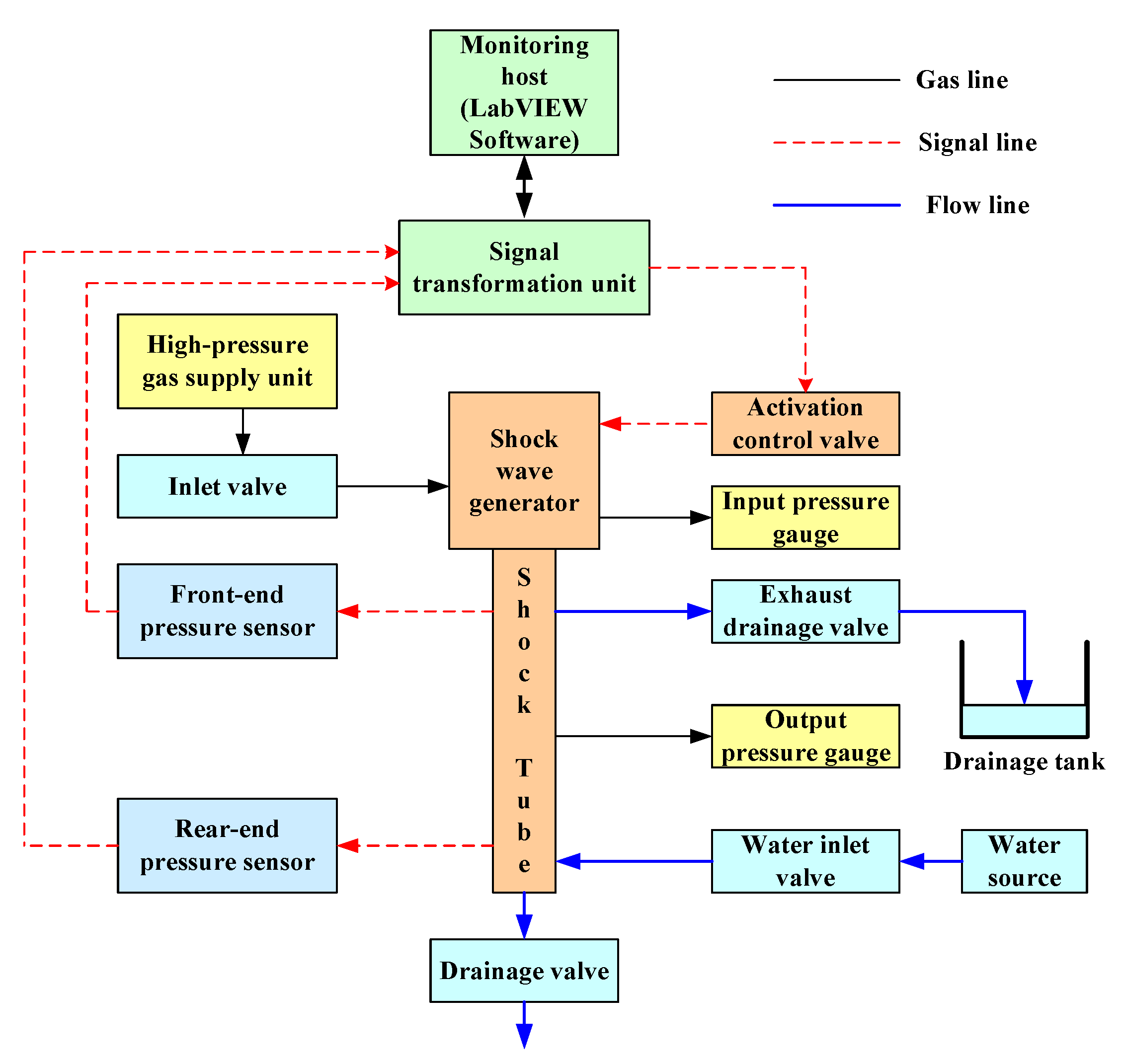
Figure 6.
Entity of the shock wave monitoring system.
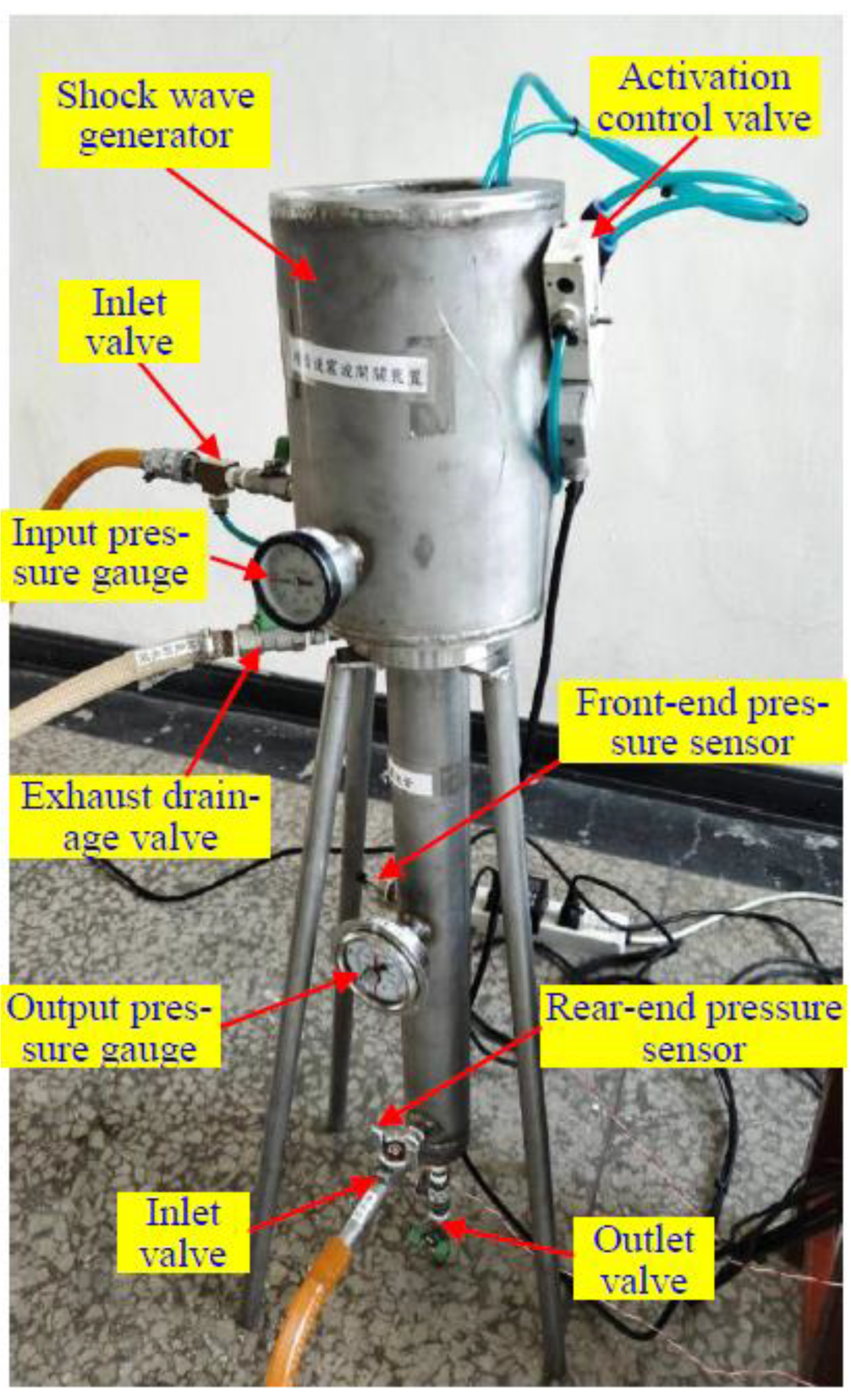
Figure 7.
Startup screen of the monitoring software.
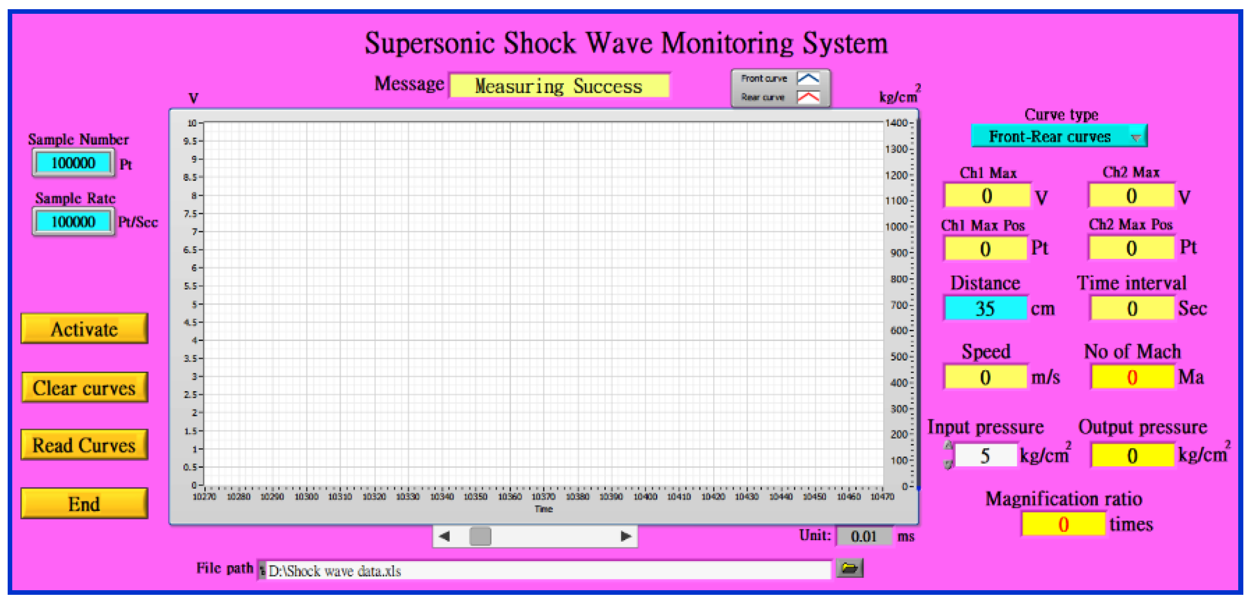
Figure 8.
Shock wave monitoring results.
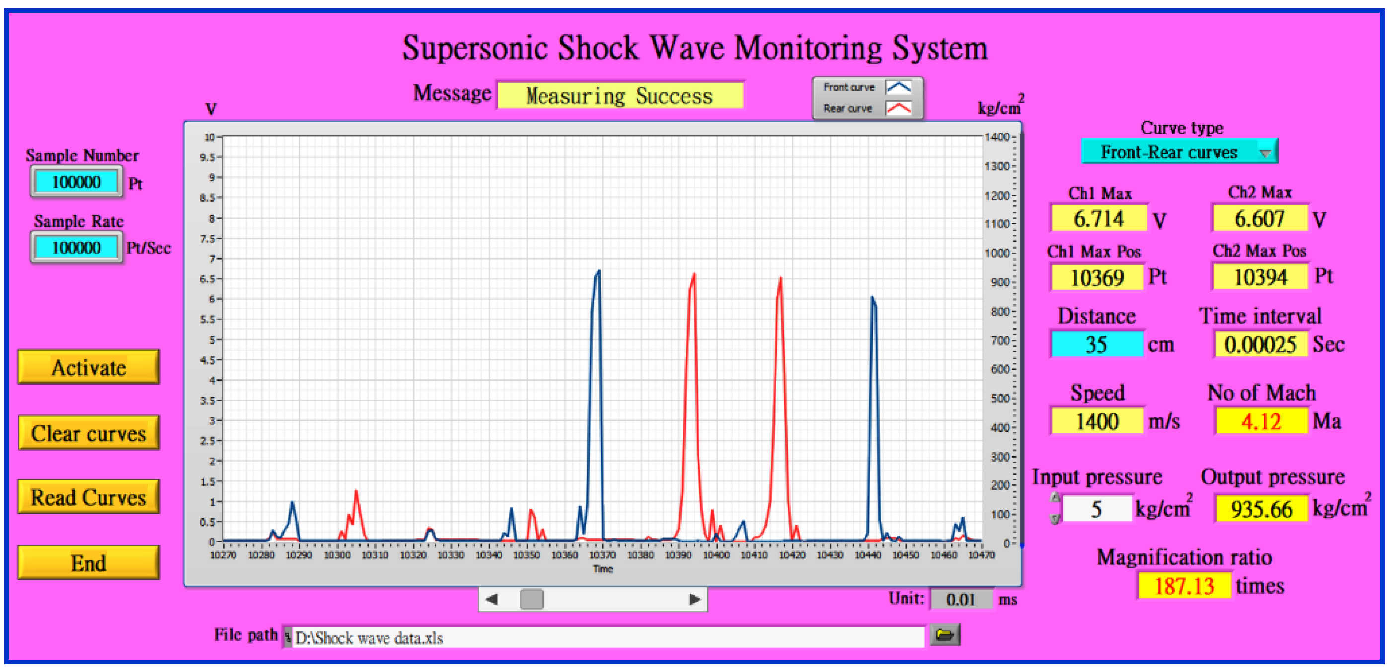
Figure 9.
Pressure change, as shown by the magnetic output pressure gauge. (a) Before shock wave monitoring; (b) After shock wave monitoring.
Figure 9.
Pressure change, as shown by the magnetic output pressure gauge. (a) Before shock wave monitoring; (b) After shock wave monitoring.
Figure 10.
The architecture of the power generation system driven by supersonic shock waves.
Figure 11.
The entity of the power generation system driven by supersonic shock waves.
Figure 12.
A light bulb box with three bulbs turned on.
Figure 13.
The control process of shock waves-driven power generation.
Figure 14.
Execution screen of the power generation monitoring software.
Figure 15.
Display screen of power generation monitoring experiment results.

Table 1.
Statistics of shock wave monitoring results.
| No. | Δt (s) | vx (m/s) | Mx (Mach) | pout (kg/cm2) | rp |
| 1 | 0.00025 | 1400 | 4.12 | 935.7 | 187.14 |
| 2 | 0.00024 | 1458.33 | 4.29 | 942.85 | 188.57 |
| 3 | 0.00024 | 1458.33 | 4.29 | 943.27 | 188.65 |
| 4 | 0.00027 | 1296.3 | 3.81 | 906.01 | 181.2 |
| 5 | 0.00027 | 1296.3 | 3.81 | 908.49 | 181.7 |
| 6 | 0.00021 | 1666.67 | 4.9 | 964.94 | 192.99 |
| 7 | 0.00022 | 1590.91 | 4.68 | 956.19 | 191.24 |
| 8 | 0.00022 | 1590.91 | 4.68 | 956.57 | 191.31 |
| 9 | 0.00022 | 1590.91 | 4.68 | 956.01 | 191.2 |
| 10 | 0.00023 | 1521.74 | 4.48 | 951.92 | 190.38 |
| 11 | 0.00026 | 1346.15 | 3.96 | 931.17 | 186.23 |
| 12 | 0.00025 | 1400 | 4.12 | 938.37 | 187.67 |
| 13 | 0.00026 | 1346.15 | 3.96 | 926.23 | 185.25 |
| 14 | 0.00026 | 1346.15 | 3.96 | 928.19 | 185.64 |
| 15 | 0.00021 | 1666.67 | 4.9 | 965.08 | 193.02 |
| 16 | 0.00022 | 1590.91 | 4.68 | 957.25 | 191.45 |
| 17 | 0.00022 | 1590.91 | 4.68 | 958.81 | 191.76 |
| 18 | 0.00022 | 1590.91 | 4.68 | 958.75 | 191.75 |
| 19 | 0.00023 | 1521.74 | 4.48 | 950.7 | 190.14 |
| 20 | 0.00025 | 1400 | 4.12 | 939.33 | 187.87 |
| Avg | 0.00024 | 1480.33 | 4.36 | 943.31 | 188.7 |
Table 2.
The average values of relevant monitoring data in each period.
| period | 0-bulb | 1-bulb | 2-bulbs | 3-bulbs |
| fs-avg-k (Hz) | 0.42 | 0.54 | 0.68 | 0.81 |
| rs-avg-k (rpm) | 1262.52 | 1243.65 | 1204.34 | 1170.82 |
| fg-avg-k (L/min) | 143.83 | 176.79 | 197.15 | 233.27 |
| Vp-avg-k (V) | 28.38 | 26.79 | 25.46 | 24.44 |
| Ip-avg-k (mA) | 0 | 51.33 | 98.63 | 143.26 |
| Ep-avg-k (mW) | 0 | 1375.71 | 2514.68 | 3501.15 |
Disclaimer/Publisher’s Note: The statements, opinions and data contained in all publications are solely those of the individual author(s) and contributor(s) and not of MDPI and/or the editor(s). MDPI and/or the editor(s) disclaim responsibility for any injury to people or property resulting from any ideas, methods, instructions or products referred to in the content. |
© 2024 by the authors. Licensee MDPI, Basel, Switzerland. This article is an open access article distributed under the terms and conditions of the Creative Commons Attribution (CC BY) license (https://creativecommons.org/licenses/by/4.0/).
Copyright: This open access article is published under a Creative Commons CC BY 4.0 license, which permit the free download, distribution, and reuse, provided that the author and preprint are cited in any reuse.


