
Submitted:
16 April 2024
Posted:
17 April 2024
You are already at the latest version
Abstract
With the ever-growing emphasis on global decarbonization and rapid increases in the power density of electronics equipment in recent years, new methods and lightweight materials have been developed to manage heat load as well as interfacial stresses associated with Coefficient of Thermal Expansion (CTE) mismatch between components. The Al-Si system provides an attractive combination of CTE performance and high thermal conductivity whilst being a very lightweight option. Such materials are of interest to industries where thermal management is a key design criterion, such as aerospace, automotive, consumer electronics, defense, EV and space. This paper will describe the development and manufacture of a family of high-performance hypereutectic Al-Si alloys (AyontEX™) by a powder metallurgy method. These alloys are of particular interest for structural heat sink applications that require high reliability under thermal cycling (CTE of 17μm/(m·°C)) as well as reflective optics and instrument assemblies that require good thermal and mechanical stability (CTE of 13μm/(m·°C)). Critical performance relationships are presented, coupled with the microstructure, physical and mechanical properties of these Al-Si alloys.
Keywords:
CTE
; Heatsink
; HIP
; Hypereutectic
; Mechanical Alloying
; Metal Matrix Composite
; MMC
; Powder Metallurgy
; Reflective Optics
; Thermal Stability
1. Introduction
With the ever-growing emphasis on global decarbonization and rapid increases in the power density of electronics equipment in recent years, thermal management is an escalating engineering challenge. Thereby emphasis on designing systems that allow heat to be transported, stored, or expelled in a manner that enables key system elements to operate with high reliability within a specific temperature range is essential [1]. This raises a need for new methods and lightweight materials to manage heat load as well as interfacial stresses associated with Coefficient of Thermal Expansion (CTE) mismatch between components. Example materials include Metal Matrix Composites (MMCs), such as Aluminium-Silicon Carbide (Al-SiC), and Beryllium-Beryllium Oxide (Be-BeO). Metallic systems can also be applicable however, such as Aluminum-Beryllium (Al-Be) and Aluminum-Silicon (Al-Si) alloys. Each of these material systems provides a unique set of performance properties and manufacturing challenges.
The Al-Si system provides an attractive combination of tailorable CTE and high thermal conductivity, while supporting lightweight design. Al-Si alloys are of interest for structural heat sink applications that require high reliability under thermal cycling, where a CTE of 17μm/(m·°C) is desirable to minimize strain due to CTE mismatch with mating copper components. Reflective optics and instrument assemblies are also application areas, where a CTE close to 13μm/(m·°C) is necessary to match the nickel plating and provide good thermal stability over broad operating temperature ranges [2,3,4,5].
Production of high Si Al-based alloys via traditional liquid-state processing routes can be problematic due to the challenges posed to achieve good control of the size and morphology of the primary Si phase [6]. Often this can mean that complex alloying additions or unique solidification processing methods are necessary to achieve the properties necessary in high-performance applications [7,8]. In contrast, manufacture via a powder metallurgy route enables a wider range of compositions and can provide a greater strength, homogeneous microstructure associated mechanical integrity [9,10]. What’s more, powder metallurgy can provide a near-net shape capability, which has been proven to lead to reduced waste generation and lower energy consumption per unit mass in comparison to traditional forming methods [11]. By processing in the solid-state, any possible detrimental diffusional or chemical reactions between constituent phases can be minimized. Avoiding molten processing allows the creation of non-equilibrium phase structures. This enables extensive opportunities for novel and interesting material combinations to enhance performance beyond traditional engineering materials.
Mechanical alloying is a solid-state mixing process combining MMC materials and metallic alloys using powder metallurgy methods. As no melting is required, the reinforcement volume fraction and particle size are controlled by raw material selection. Thereby, this process enables precise control of reinforcement particle sizes with higher reinforcement volume fractions. Both of which are critical to maximizing and optimising the property benefits that can be achieved with MMC systems relative to the monolithic material [12]. Mechanical alloying was first developed in the 1960s with the aim of fabricating a nickel-based superalloy with homogeneous distribution of oxide reinforcements for gas turbine applications [13]. Since then, many material combinations have been explored [14,15,16,17,18,19,20,21,22,23,24,25,26]. The basic principle is the cyclical welding and fracture of ductile and brittle powders via repetitive impact, resulting in a distribution of reinforcement within the metallic matrix particles [27]. Optimization of key parameters is however necessary to achieve a homogeneous and stable process [24,25,26,28,29]. This composite powder then acts as an input into downstream consolidation processes such as Hot Isostatic Pressing (HIP) or extrusion.
Materion’s mechanical alloying and powder metallurgy technologies have been used for decades to produce commercially available particle reinforced aluminium-SiC SupremEX® MMCs [30,31]. A schematic summarizing this powder metallurgy route is given by Figure 1. These MMCs have been shown to display a very fine and homogeneous microstructure, with precise control of particle sizes [32]. The resultant composite materials are known to be isotropic with high modulus, strength, wear and fatigue performance [30,33], but maintain the machining, fabrication, coating, and processing characteristics of conventional aluminium alloys.
This paper will describe manufacturing of hypereutectic Al-Si alloys via a powder metallurgy route utilizing Materion’s novel mechanical alloying process. Due to the flexibility of the manufacturing route, this lightweight material system has been finely tuned to achieve the specific and desirable CTE values referenced above. A detailed understanding of the relationship between chemistry and CTE has been developed. Critical performance relationships such as this will be presented, coupled with the microstructure, physical and mechanical properties of these Al-Si alloys.
2. Materials and Methods
Materion’s powder metallurgy routes were leveraged to combine elemental Si with Al alloy powders. This mixture was mechanically alloyed until the Si was distributed within the Al matrix, with an overall refined and homogeneous microstructure. To achieve an optimal balance of mechanical and thermal properties, a 6063-alloy composition was selected along with high purity silicon powders. A series of samples with chemistry ranging from 15-55wt% Si were processed. These were then canned, degassed, and compacted by HIP to achieved fully dense, cylindrical billets, approximately Ø100mm x 170mm in size.
Samples for CTE evaluation were extracted from these billets and tested per ASTM E228-17, to understand the relationship between composition and this critical property. This enabled derivation of the necessary compositions to achieve a CTE close to the target values of 17μm/(m·°C) and 13μm/(m·°C), as is depicted by Figure 2. Larger scale cylindrical billets (approx. Ø150mm x 600mm) and cuboid billets (approx. 180mm x 180mm x 300mm) were subsequently manufactured at the derived compositions using the same manufacturing conditions to confirm scalability of the process. These materials were then tested in detail to confirm microstructure, room temperature tensile properties, density, and electrical conductivity. Tensile testing was carried out using an Instron 3369 loading frame with a 50 kN capacity. Cylindrical specimens were used, with a 5mm diameter and 25mm gauge length. Test control was by constant strain rate of 1.4x10⁻⁴ mm/mm/s, until failure. Microstructural analysis was completed using a Zeiss AxioLab5 optical microscope equipped with ZEN core imaging software. CTE was again evaluated per ASTM E228-17 but over a broader temperature range of -100°C to 200°C, whilst room temperature thermal diffusivity and specific heat capacity were measured per ASTM E1461-13 and ASTM E1269-11, respectively. Thermal conductivity was calculated as the product of thermal diffusivity, specific heat capacity and density per Equation 1 of ASTM E1461-13. Finally, a series of components representing example applications for each of the alloy components were produced, to assess manufacturability.
3. Results
3.1. Microstructure
An ultra-fine and homogeneous distribution of Si particles within the Al alloy was achieved for all Si contents tested, as Figure 3 shows. It can also be observed that the mechanically alloyed powder is generally blocky and irregular in shape, across all compositions. This is consistent with Al-SiC materials mechanically alloyed by the same process [30,31]. In the consolidated (post-HIP) form the microstructure was seen to be consistent in all tested directions, indicating isotropic properties as expected. Typical optical micrographs of the 13μm/(m·°C) alloy are presented in Figure 4. Here, the ultrafine and homogeneous microstructure is again evident. The primary silicon size was observed to have an average size of 3-4μm diameter, with almost all silicon particles within the 1-7μm range.
3.2. Coefficient of Thermal Expansion
The achieved CTE matches to commercially pure copper and nickel are summarized by Figure 5, via comparison to reference data from literature [34,35,36,37]. This shows an exact mean CTE match to copper for the 20-50°C temperature range. The 17μm/(m·°C) Al-Si alloy was determined to have a marginally lower CTE for temperatures below room temperature and marginally higher CTE at temperatures greater than 50°C. The mean CTE value at all temperatures, as well as the rate of change of CTE with respect to temperature for the Al-Si alloy is significantly lower than that of unreinforced aluminium alloys (~23μm/(m·°C)), and thus provides a relatively excellent CTE match to copper. The prior heat-treatment condition of this Al-Si alloy was seen to have negligible influence over the temperature range tested.
A close CTE match was observed to nickel, with the 13μm/(m·°C) Al-Si alloy displaying a marginally higher CTE for the temperatures tested. The rate of change of CTE with respect to temperature for this Al-Si alloy and nickel is similar over the temperature range tested. Again, no influence of the prior heat treatment condition was observed.
3.3. Additional Physical and Mechanical Properties
Beyond CTE, additional key material properties of the tested Al-Si alloys are presented by Table 1. A good balance of strength and conductivity for thermal management applications is displayed by these alloys. Given the large ranges in strength for AyontEX quoted in Table 1, typical engineering stress-strain curves for this alloy are provided by Figure 6 and true stress-strain equivalents by Figure 7.
4. Discussion
The simple rule of mixtures calculation model provided a close approximate to the measured relationship between CTE and Si content, as shown by Figure 2. The measured values were consistently slightly lower than the predicted and trended away from model at lower and higher Si content values. A possible explanation for this deviation between model and measured values is that the rule of mixtures calculation does not account for other phases than the constituent elements (e.g., Mg2Si precipitates), or the different elastic properties of matrix and reinforcement and associated thermal strains [38]. Particularly at the more extreme values of Si reinforcement (≥50%) the so-called percolation threshold may have been passed, meaning it would be inappropriate to consider the Si phase and the elastic region surrounding them to be individual particles, but more likely a continuous path of reinforcement [39]. This could explain the increased deviation from the model observed at the highest Si contents tested. The negligible effect of heat treatment condition on the CTE of these alloys can be explained by the high Si content necessary to achieve such low CTEs. This thereby limits the ability to influence properties via heat treatment.
The compositions of the two now-commercially-available alloys, AyontEX 17 (with a CTE of 17μm/(m·°C)) and AyontEX 13 (with a CTE of 13μm/(m·°C)), were derived from the measured CTE curve in Figure 2. The fine and homogeneous microstructures achieved (Figure 3 and Figure 4) are important towards enabling the application of high throughput and available downstream machining and finishing processes to these alloys. Ease of machinability relative to equivalent liquid-state processed Al-Si alloys or other lightweight, low-CTE materials (e.g., MMCs) can provide a significant benefit in overall part cost by increasing throughput and decreasing tooling costs. Such benefits can be clearly realized in the manufacture of complex, high performance components where fine surface finish and high tolerance is required. Several common machining processes, including milling, turning, drilling, tapping and EDM have been successful performed on this material, many of which are highlighted by Figure 8. Here, the thin wall sections at the top of the part are 0.8mm thick and the EDM’d slot at bottom is 0.5mm thick and 32mm deep. These features were achieved with standard, high throughput methods and no special parameters.
Example components representing typical applications for each of the alloys are presented by Figure 9. The miniature structural heatsink in Figure 9(a) is 58x40x5mm in size, highlighting the ability to carry out precise milling, drilling, and tapping operations with the AyontEX 17 material. The AyontEX 13 mirror substrate presented by Figure 9(b) is approx. 150mm diameter. This was rough machining using standard carbide tooling and completed with poly-crystalline diamond tooling. Given the low-density (2.54 g/cm3) and complex lightweighting geometry, this mirror has a mass of 0.2kg. Such lightweight mirror design is highly beneficial for airborne applications.
An emerging topic in lightweight optical mirror design is additive manufacturing to enable complex structures for material and load optimization [40,41,42]. It is then an interesting topic for future exploration to develop and apply additive manufacturing techniques to the AyontEX 13 material, given the material already exists in a powder form as per the powder metallurgy route presented here. Such development would combine the material property benefits discussed here with the design freedom of additive manufacturing for high-performance applications.
Close CTE matches with mating materials are important in the applications discussed above. The results presented in Figure 5 confirm that a precise CTE match to the reference data for copper and nickel were achieved with the manufactured alloys over the full -100-200°C test range. Particularly, for AyontEX 13 the rate of change of CTE with respect to temperature was very consistent with that of nickel. This is important for reflective optical and instrument systems, where precise CTE matches to nickel plating layers are critical for both dimensional and thermal stability over broad operating conditions [2,3,4,5]. It should be noted, that in the case of electroless plating, the nickel material will contain some level of phosphorus. The CTE curve for NiP [3,4,43], is very similar to the commercially pure nickel CTE data used for comparison in Figure 5. It can therefore be said the AyontEX 13 material provides an excellent CTE match to both electrolytic and electroless Ni plating for application in high-precision optical mirrors. Of course, the ability to Ni plate to the material is critical for such applications. An example of successful application of electrolytic nickel plating to AyontEX 13 is given by Figure 10. Electroless NiP plating solutions are also compatible, should this be more preferred for the application.
As expected, increasing the Si content resulted in a linear decrease in density and linear increase in elastic modulus. Increasing Si content was seen to result in a decrease in thermal conductivity, but also a decrease in the dependence of heat treatment condition on the thermal conductivity. For AyontEX 17, which has a lower Si vol%, the mean thermal conductivity was determined to be 160 W/mK in the T6 condition, but 170 W/mK the T1 (air-cooled from HIP) condition a difference of ~6%. In contrast for the higher Si vol% composition, AyontEX 13, heat treatment condition was found to have negligible impact on the thermal conductivity.
This high thermal conductivity of AyontEX 17 in the T1 condition, coupled with the precise CTE match to Cu over 0-100ºC temperatures ranges (see Figure 5) highlights the use for structural heatsink assemblies. As a direct replacement for 6061 Al for example, AyontEX 17 provides increased modulus, decreased CTE and density, whilst maintaining thermal conductivity. This is critical in enabling high power density devices where heat load must be efficiently managed as well as interfacial stresses driven by CTE mismatch to mating Cu components.
Similar trends with respect to Si loading were observed regarding the mechanical properties, and in particular the yield strength. The 0.2% proof strength of AyontEX 17 was seen to almost double from 170 MPa in T1 to 300 MPa in T6, with significant differences in ultimate tensile strength and strain to failure. These differences are depicted by stress-strain curves given by Figure 6 and Figure 7. This data was generated on billet material directly following the HIP process. The application of secondary forming processes, such as forging and extrusion, enhance ductility in finished product. This remains an interesting topic for further exploration to allow close to shape forming operations. By comparison the mechanical properties at higher Si vol% material have a much lower dependence on heat treatment condition, as outlined by Figure 11. These effects can be explained by simply considering that as the Si vol% is increased, vol% of the 6063-alloy decreases. This in turn means less Mg is available within the alloy for Mg2Si precipitation strengthening effects through heat treatment. Additionally, as the quantity of primary Si phase particles is increased the relative distance between adjacent Si particles is decreased and thus strengthening because of the primary Si phase becomes a more dominant mechanism relative to the Mg2Si precipitation phases.
The increasing influence of the Si phase as the Si vol% was increased to more extreme values (≥50%) led to the ensuing material to become more brittle. This resulted in an associated decrease in both 0.2% proof strength and ultimate tensile strength, as captured by Figure 11. For such compositions the proportion of primary Si phase is so significant that fracture can occur at the alloy-Si particle interface, due to Si particle clustering or the percolation effects described above. The severity of such effects within particulate MMC materials is well understood [44]. In contrast, at the more modest Si vol%, such as those used for the AyontEX 17 and AyontEX 13 materials, fracture occurs predominantly through the ductile 6063 alloy matrix phase.
Deeper exploration of the microstructural effects and phases at play in these hypereutectic Al-Si alloys provides an interesting avenue for future study. Particularly the impacts of using recycled Al alloy as an input raw material and the associated high Fe content could be interesting. Previous studies have identified effective Si to have a significant impact on the performance of 6000-series aluminium alloys with high Fe content [45]. Exploration of how this effect translates to the more extreme Si levels in these hypereutectic alloys would be an interesting. Particularly so, with a view towards possible incorporation of recycled or secondary aluminium sources in the AyontEX alloys to increase the circularity of these high-performance materials.
5. Conclusions
A family of now-commercially-available high-performance hypereutectic Al-Si alloys (AyontEX™) have been developed with precise CTE matches to copper and nickel. Core material properties for the intended applications have been characterized, along with the key manufacturability considerations. The fine and homogeneous microstructure provides enhanced performance and manufacturability relative to equivalent liquid-state processed alloys. Further development work for these Al-Si alloys is directed towards the use of mechanical alloying technology for lower CTE values, as well as testing the CTE of existing alloys over a broader temperature range. Development of additional fabricated forms via forging and extrusion for increased ductility and product form flexibility is also under investigation. Exploration of the secondary of recycled aluminium sources as a raw material in this manufacturing process, and associated understanding of the effects of associated impurity elements, is an area for possible future study also.
Another potential application for Materion’s mechanical alloying technology and these alloys moving forwards is additive manufacturing. Particularly for lightweight, high-precision optical mirror manufacture the AyontEX 13 composition is interesting. More broadly however, the mechanical alloying process employed in this study allows for compositions to be tailored to suit the requirements for additive methods in terms of alloy and reinforcement composition and microstructures. The process also has sufficient scalability to provide an industrial solution. Due to this ability to mix a wide range of materials to produce composite powders it may be possible to produce new and novel powders as an input for additive process. This could lead to additive manufacturing material and property options that do not exist today.
These research areas provide exciting opportunities for further exploitations of mechanical alloying technology, and powder metallurgy in general, towards developing new products to meet the needs of its customers in global markets such as aerospace, high-performance automotive, space and defense.
Author Contributions
Conceptualization, A.T., A.F., F.G., N.F. and M.A.; Methodology, P.L., A.T. and F.G.; Experimentation, P.L. & J.N; Analysis, P.L & A.T.; Writing – Original Draft Preparation, P.L.; Writing – Review & Editing, A.T., A.F., F.G., N.F. and M.A.; Supervision, A.T and A.F. All authors have read and agreed to the published version of the manuscript.
Funding
This research received no external funding.
Data Availability Statement
Requests to access the datasets should be directed to the authors.
Acknowledgments
The authors thankfully acknowledge the support provided by Outpost Technologies Inc. in the manufacture of the example mirror component presented in Figure 9(b).
Conflicts of Interest
The authors declare no conflicts of interest. The funders had no role in the design of the study; in the collection, analyses, or interpretation of data; in the writing of the manuscript; or in the decision to publish the results.
References
- M. Acreman, P. Lewis and N. Farrah, Advanced Materials for Defense Applications - Part 2: Thermal Management. 2022. Available online: https://materion.com/about/new-at-materion/specialty-materials-for-defense-part-2-thermal-management.
- Hibbard, D.L. Electroless Nickel for Optical Applications. Adv. Mater. Opt. Precis. Struct. A Crit. Rev. 1997, 10289, 173–199. [Google Scholar]
- R.-R. Rohloff, A. Gebhardt, V. SchÃjnherr, S. Risse, J. Kinast, S. Scheiding and T. Peschel, "A novel athermal approach for high-performance cryogenic metal optics," in SPIE 7739, Modern Technologies in Space- and Ground-based Telescopes and Instrumentation, San Diego, CA, 2010.
- Kinast, J.; Grabowski, K.; Rohloff, R.-R.; Risse, S.; Tünnermann, A. Dimensional stability of metal optics on nickel plated AlSi40. In Proceedings of the International Conference on Space Optics, Tenerife, Spain; 2014; p. 79. [Google Scholar]
- Kinast, J.; Tünnermann, A.; Undisz, A. Dimensional Stability of Mirror Substrates Made of Silicon Particle Reinforced Aluminum. Materials 2022, 15, 2998. [Google Scholar] [CrossRef]
- Zhang, R.; Zou, C.; Wei, Z.; Wang, H. Effect of High Pressure and Temperature on the Evolution of Si Phase and Eutectic Spacing in Al-20Si Alloys. Crystals 2021, 11, 705. [Google Scholar] [CrossRef]
- Mostafa, A.; Alshabatat, N. Microstructural, Mechanical and Wear Properties of Al–1.3%Si Alloy as Compared to Hypo/Hyper–Eutectic Compositions in Al–Si Alloy System. Crystals 2022, 12, 719. [Google Scholar] [CrossRef]
- Jiandon, P.; Talangkun, S. Microstructural Modification Hardness and Surface Roughness of Hypereutectic Al-Si Alloys by a Combination of Bismuth and Phosphorus. Crystals 2022, 12, 1026. [Google Scholar] [CrossRef]
- Rosso, M. Ceramic and metal matrix composites: Routes and properties. J. Mater. Process. Technol. 2006, 175, 364–375. [Google Scholar] [CrossRef]
- Ujah, C.O.; Kallon, D.V.V. Trends in Aluminium Matrix Composite Development. Crystals 2022, 12, 1357. [Google Scholar] [CrossRef]
- Kruzhanov, V.; Arnhold, V. Energy consumption in powder metallurgical manufacturing. Powder Met. 2012, 55, 14–21. [Google Scholar] [CrossRef]
- Vine, W.; Goodwin, P. Feasibility of Synthesising Lightweight Nanophase Al Materials by Mechanical Alloying. Mater. Sci. Forum 2000, 331–337, 1145–1150. [Google Scholar] [CrossRef]
- Benjamin, J.S. Mechanical Alloying. Sci. Am. 1976, 234, 40–48. [Google Scholar] [CrossRef]
- Suryanarayana, C.; Al-Aqeeli, N. Mechanically alloyed nanocomposites. Prog. Mater. Sci. 2013, 58, 383–502. [Google Scholar] [CrossRef]
- Narayan, S.; Rajeshkannan, A. Workability Behavior of Powder Metallurgy Carbide Reinforced Aluminum Composites During Hot Forging. Mater. Manuf. Process. 2014, 30, 1196–1201. [Google Scholar] [CrossRef]
- Zhou, H.; Zhang, C.; Han, B.; Qiu, J.; Qin, S.; Gao, K.; Liu, J.; Sun, S.; Zhang, H. Microstructures and Mechanical Properties of Nanocrystalline AZ31 Magnesium Alloy Powders with Submicron TiB2 Additions Prepared by Mechanical Milling. Crystals 2020, 10, 550. [Google Scholar] [CrossRef]
- Umeda, J.; Nishimura, N.; Fujii, H.; Jia, L.; Kondoh, K. In-Situ Formed Al3Zr Compounds Reinforced Al Composites and Tribological Application. Crystals 2021, 11, 227. [Google Scholar] [CrossRef]
- Wu, Y.; Luo, S.; Wu, J.; Guo, B.; Wu, Z.; Chen, B.; Yu, Z.; Zhang, Z.; Li, W. Development and Characterization of CrCoNi Medium Entropy Alloy Particles Reinforced Aluminum Matrix Composite. Crystals 2022, 12, 1452. [Google Scholar] [CrossRef]
- Arora, G.S.; Saxena, K.K.; Mohammed, K.A.; Prakash, C.; Dixit, S. Manufacturing Techniques for Mg-Based Metal Matrix Composite with Different Reinforcements. Crystals 2022, 12, 945. [Google Scholar] [CrossRef]
- Ariff, A.H.M.; Lin, O.J.; Jung, D.-W.; Tahir, S.M.; Sulaiman, M.H. Rice Husk Ash as Pore Former and Reinforcement on the Porosity, Microstructure, and Tensile Strength of Aluminum MMC Fabricated via the Powder Metallurgy Method. Crystals 2022, 12, 1100. [Google Scholar] [CrossRef]
- Fan, M.; Zhao, F.; Liu, Y.; Yin, S.; Peng, S.; Zhang, Z. Zinc Matrix Composites Reinforced with Partially Unzipped Carbon Nanotubes as Biodegradable Implant Materials. Crystals 2022, 12, 1110. [Google Scholar] [CrossRef]
- Kushwaha, A.K.; Misra, M.; Menezes, P.L. Effect of Magnesium Dopant on the Grain Boundary Stability of Nanocrystalline Aluminum Powders during Cryomilling. Crystals 2023, 13, 541. [Google Scholar] [CrossRef]
- Sübütay, H.; Savklıyıldız, İ. Effect of High-Energy Ball Milling in Ternary Material System of (Mg-Sn-Na). Crystals 2023, 13, 1230. [Google Scholar] [CrossRef]
- Yan, Q.; Chen, B.; Zhou, X.; Kondoh, K.; Li, J. Effect of Metal Powder Characteristics on Structural Defects of Graphene Nanosheets in Metal Composite Powders Dispersed by Ball Milling. Crystals 2021, 11, 260. [Google Scholar] [CrossRef]
- Nava-Dino, C.G.; Ríos, J.P.F.-D.L.; Maldonado-Orozco, M.C.; Sánchez-Carrillo, M.; Bautista-Margulis, R.G.; Delgado, A.D.l.C.; Almeraya-Calderón, F. Electrochemical Noise Response of Cr2Nb Powders Applying Mechanical Alloying. Crystals 2022, 12, 482. [Google Scholar] [CrossRef]
- Ibn Gharsallah, H.; Azabou, M.; Khitouni, M.; Daza, J.; Suñol, J.-J. Study of the Microstructural, Thermal, and Magnetic Properties of High-Energy Ball-Milled Nanocrystalline Fe(Al). Crystals 2022, 12, 1430. [Google Scholar] [CrossRef]
- ASM International, "Milling of Brittle and Ductile Materials," ASM Handbook, Volume 7, Powder Metallurgy, pp. 77-87, 2015.
- Trautmann, M.; Ahmad, H.; Wagner, G. Influencing the Size and Shape of High-Energy Ball Milled Particle Reinforced Aluminum Alloy Powder. Materials 2022, 15, 3022. [Google Scholar] [CrossRef] [PubMed]
- Raducanu, D.; Cojocaru, V.D.; Nocivin, A.; Hendea, R.E.; Ivanescu, S.; Stanciu, D.; Trisca-Rusu, C.; Serban, N.; Drob, S.I.; Campian, R.S. Microstructure Evolution during Mechanical Alloying of a Biodegradable Magnesium Alloy. Crystals 2022, 12, 1641. [Google Scholar] [CrossRef]
- Hashiguchi, D.H.; Tricker, D.; Tarrant, A.D. Mechanically alloyed aluminum metal matrix composites. Material Technologies and Applications to Optics, Structures, Components, and Sub-Systems III. San Diego, CA, USA, 2017.
- Frehn, A.; Lewis, P.; Tarrant, A. Partikelverstärkte Aluminium-Werkstoffe für Hochleistungsanwendungen. in Tagungsband 40. Hagener Symposium „Pulvermetallurgie – vielfältige Prozesse und Werkstoffe, Heimdall Verlag, Fachverband Pulvermetallurgie, Hagen, DE, 2022.
- Reiff-Musgrove, R.; Gaiser-Porter, M.; Gu, W.; Campbell, J.; Lewis, P.; Frehn, A.; Tarrant, A.; Tang, Y.; Burley, M.; Clyne, T.W. Indentation Plastometry of Particulate Metal Matrix Composites, Highlighting Effects of Microstructural Scale. Adv. Eng. Mater. 2023, 25, 2201479. [Google Scholar] [CrossRef]
- Winter, L.; Hockauf, K.; Lampke, T. Temperature and Particle Size Influence on the High Cycle Fatigue Behavior of the SiC Reinforced 2124 Aluminum Alloy. Metals 2018, 8, 43. [Google Scholar] [CrossRef]
- Nix, F.C.; MacNair, D. The Thermal Expansion of Pure Metals: Copper, Gold, Aluminum, Nickel and Iron. Phys. Rev. 1941, 60, 597–605. [Google Scholar] [CrossRef]
- Hidnert, P. Thermal expansion of copper and some of its important industrial alloys. Sci. Pap. Bur. Stand. 1921, 17, 91–159. [Google Scholar] [CrossRef]
- Hidnert, P. Thermal Expansion of Some Nickel Alloys. J. Res. Natl. Bur. Stand. 1957, 58, 89–92. [Google Scholar] [CrossRef]
- Bennett, S.J. The thermal expansion of copper between 300 and 700K. J. Phys. D Appl. Phys. 1978, 11, 777–780. [Google Scholar] [CrossRef]
- R. Morrell, "Thermal Properties of Composite Materials - Measurements, Models and Thermal Exposure Dervied Changes in MMCs and CMCs," NPL Report CMMT (A) 6, 1995.
- Sergo, V.; Meriani, S. Thermal expansion and percolation in a SiC whisker-reinforced ceramic composite. J. Mater. Sci. Lett. 1991, 10, 855–857. [Google Scholar] [CrossRef]
- Zhang, K.; Qu, H.; Guan, H.; Zhang, J.; Zhang, X.; Xie, X.; Yan, L.; Wang, C. Design and Fabrication Technology of Metal Mirrors Based on Additive Manufacturing: A Review. Appl. Sci. 2021, 11, 10630. [Google Scholar] [CrossRef]
- Zhang, K.; Xie, X.; Wang, C.; Wang, H.; Xu, F.; Wang, H.; Zhang, X.; Guan, H.; Qu, H.; Zhang, J. Optomechanical Performances of Advanced Lightweight Mirrors Based on Additive Manufacturing. Micromachines 2022, 13, 1334. [Google Scholar] [CrossRef]
- Zhang, J.; Wang, C.; Qu, H.; Guan, H.; Wang, H.; Zhang, X.; Xie, X.; Wang, H.; Zhang, K.; Li, L. Design and Fabrication of an Additively Manufactured Aluminum Mirror with Compound Surfaces. Materials 2022, 15, 7050. [Google Scholar] [CrossRef]
- Fujimori, Y.; Shimizu, M.; Kurashina, T.; Arai, S. Substrate thermal expansion coefficient effect on cracks induced by the high-heat treatment of electroplated Ni-P films for power devices. Mater. Lett. 2023, 350, 134869. [Google Scholar] [CrossRef]
- Murphy, A.; Howard, S.; Clyne, T. Characterisation of severity of particle clustering and its effect on fracture of particulate MMCs. Materials Science and Technology 1998, 14, 959. [Google Scholar] [CrossRef]
- Österreicher, J.; Arnoldt, A.; Gneiger, S.; Kunschert, G. Tolerance of Al–Mg–Si Wrought Alloys for High Fe Contents: The Role of Effective Si. Metall. Mater. Trans. A 2023, 54A, 4472–4480. [Google Scholar] [CrossRef]
Figure 1.
Schematic summarizing Materion’s mechanical alloying powder metallurgy routes.
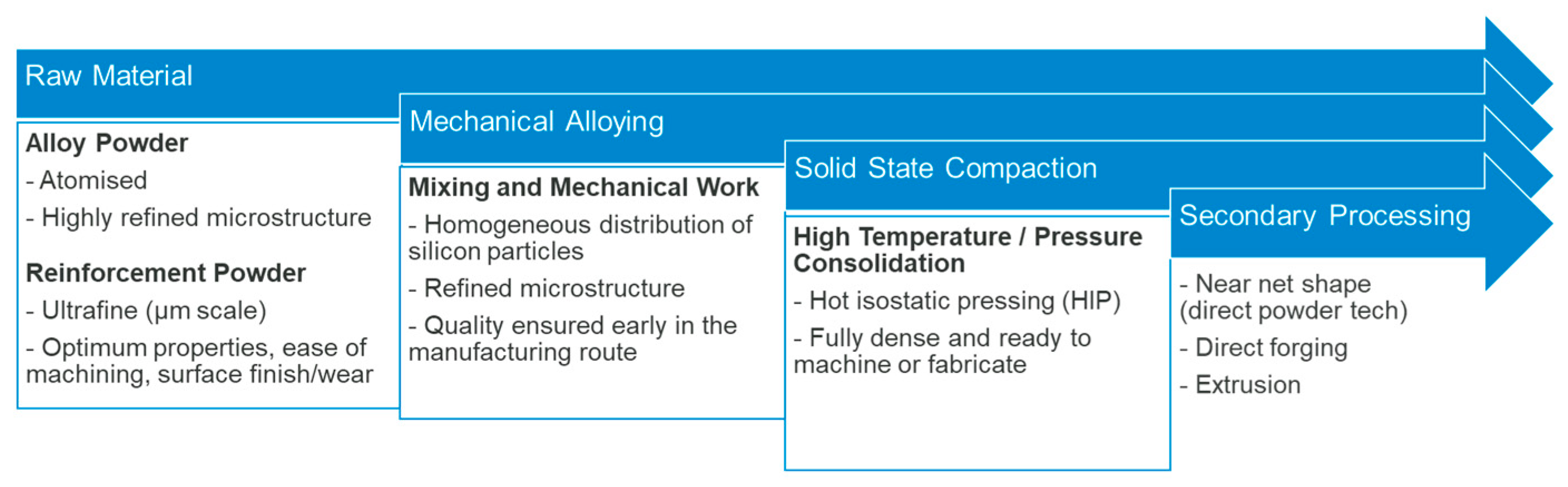
Figure 2.
Effect of Si content on CTE of the manufactured Al-Si alloys (dashed line) versus simple rule of mixtures calculation (solid line).
Figure 2.
Effect of Si content on CTE of the manufactured Al-Si alloys (dashed line) versus simple rule of mixtures calculation (solid line).
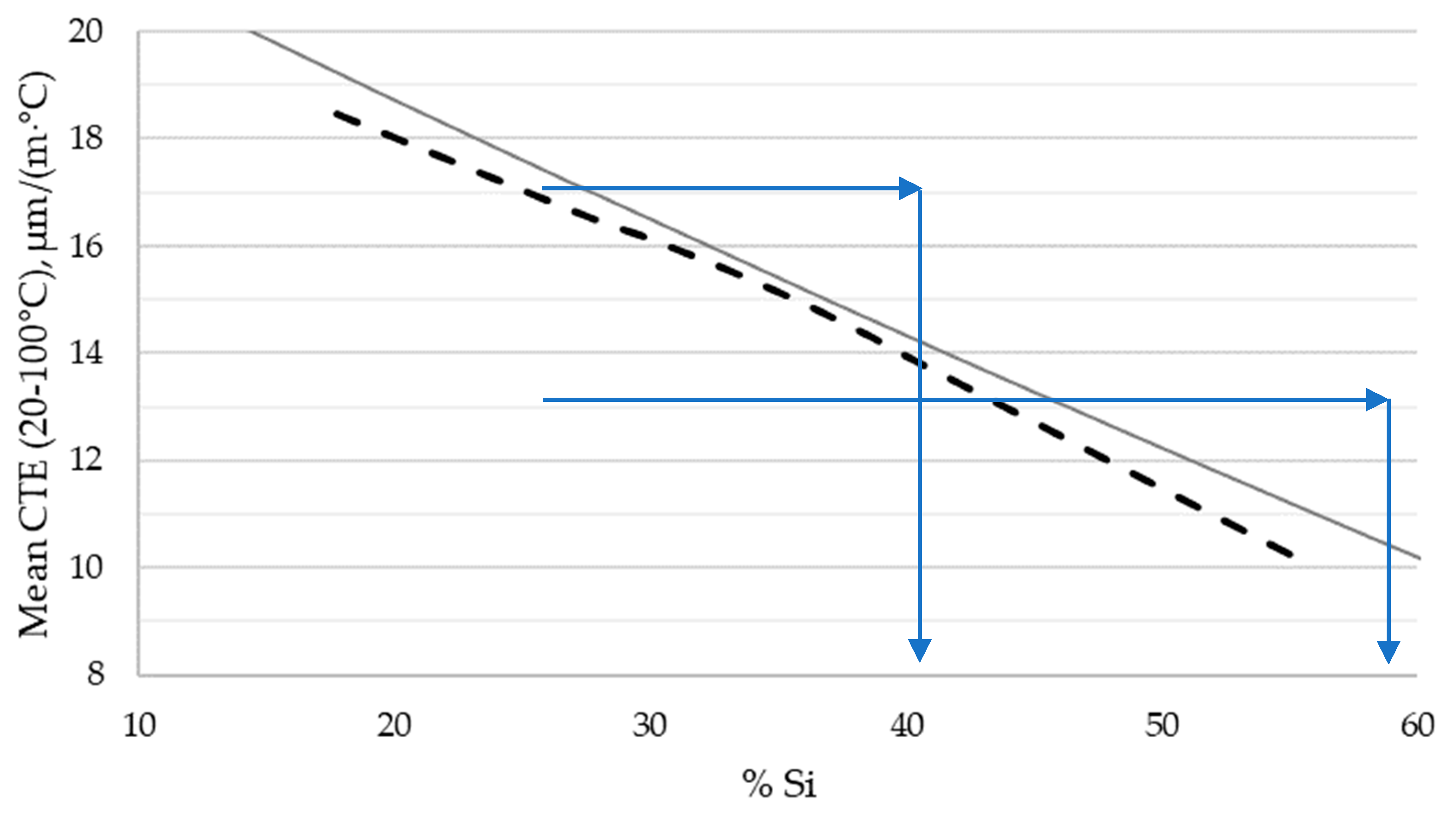
Figure 3.
Mechanically alloyed Al-Si powders at (a) 18wt% Si, (b) 27wt% Si, (c) 40wt% Si and (d) 55wt% Si. (Scale is intentionally withheld).
Figure 3.
Mechanically alloyed Al-Si powders at (a) 18wt% Si, (b) 27wt% Si, (c) 40wt% Si and (d) 55wt% Si. (Scale is intentionally withheld).
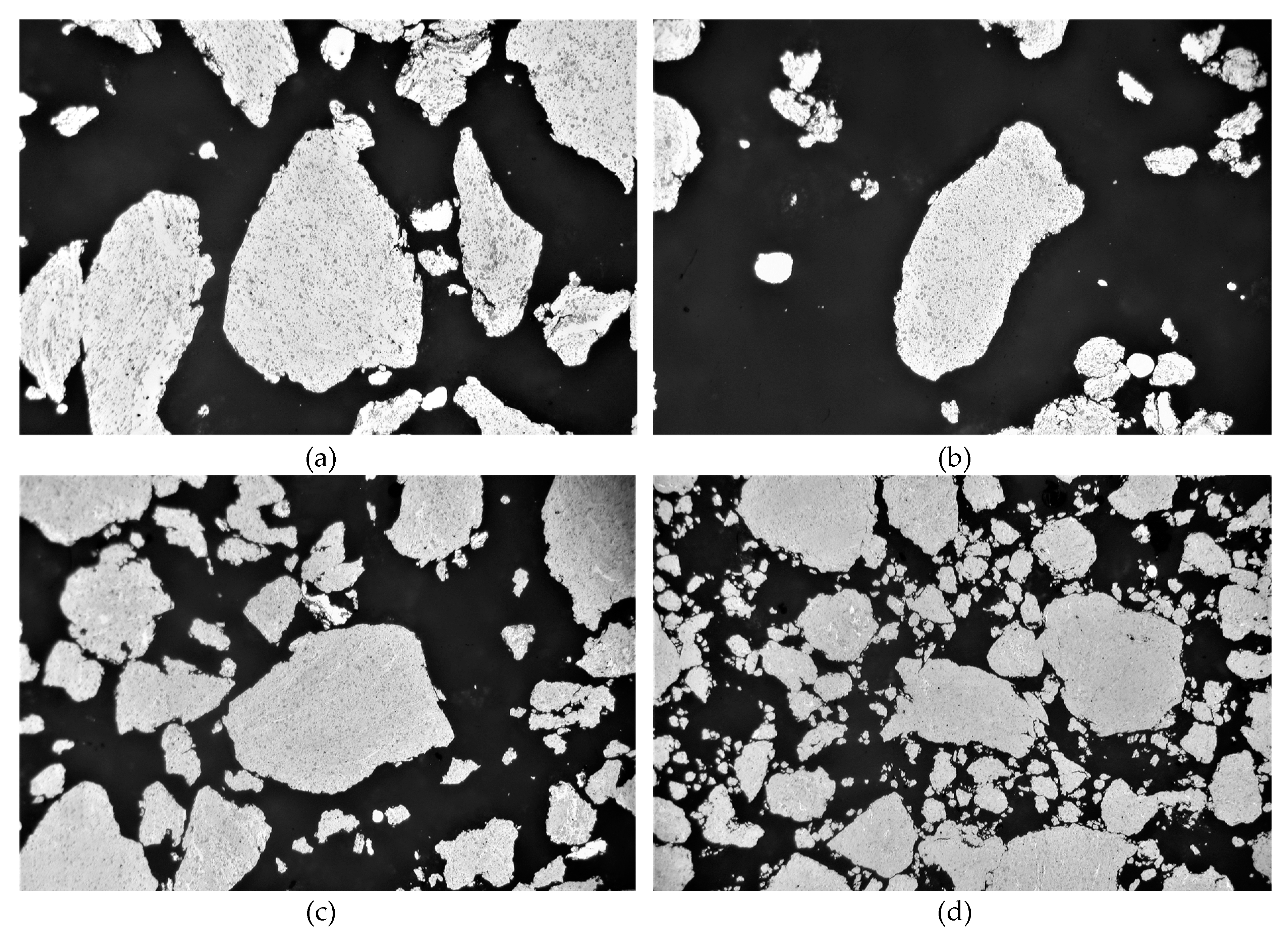
Figure 4.
AyontEX 13 optical micrographs at (a) 50x magnification and (b) 1000x magnification.
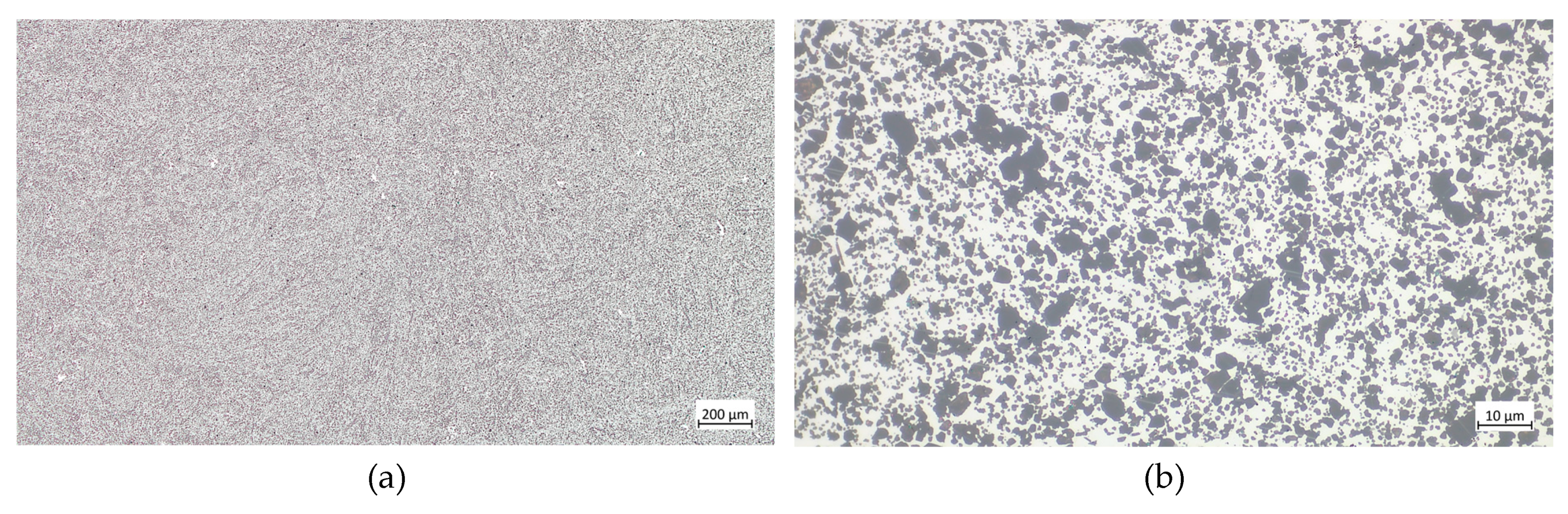
Figure 5.
Achieved CTE matches to reference data on commercially pure copper and nickel.
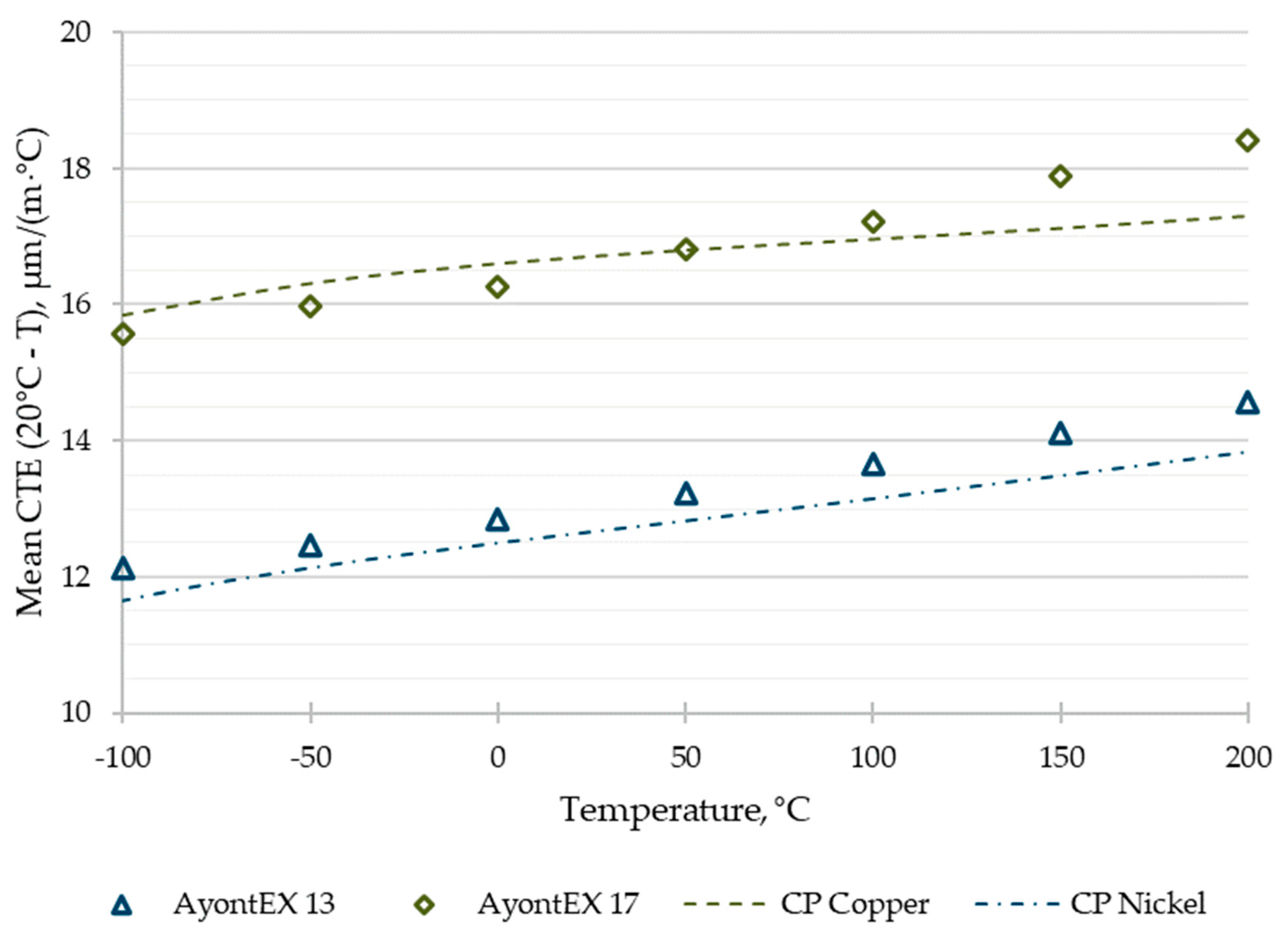
Figure 6.
Typical room temperature engineering tensile stress-strain curves for AyontEX 17 alloy in different heat treatment conditions. (T1 = air cooled from HIP, CWQ = cold water quench, PGQ = 25% polyglycol solution quench).
Figure 6.
Typical room temperature engineering tensile stress-strain curves for AyontEX 17 alloy in different heat treatment conditions. (T1 = air cooled from HIP, CWQ = cold water quench, PGQ = 25% polyglycol solution quench).
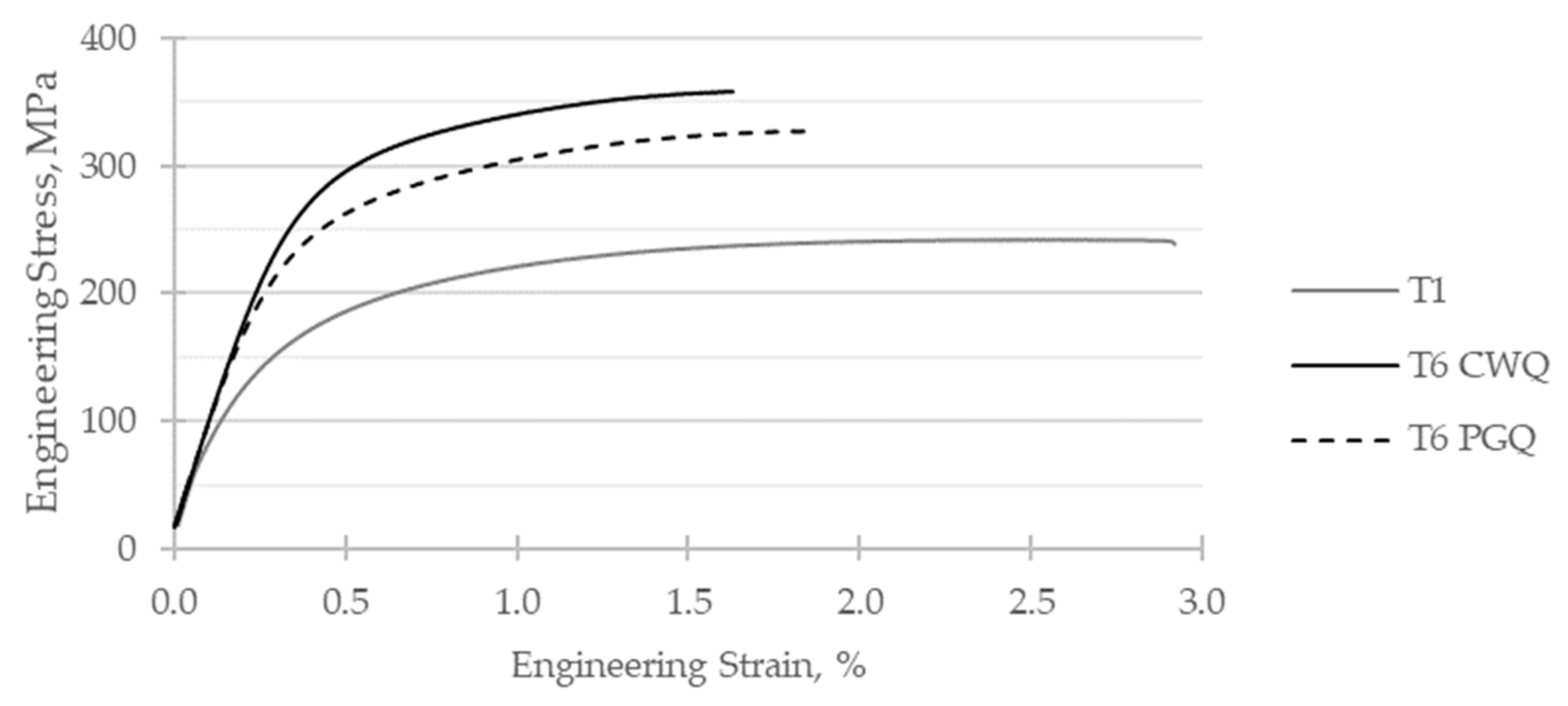
Figure 7.
Typical room temperature tensile true stress-strain curves for AyontEX 17 alloy in different heat treatment conditions. (T1 = air cooled from HIP, CWQ = cold water quench, PGQ = 25% polyglycol solution quench).
Figure 7.
Typical room temperature tensile true stress-strain curves for AyontEX 17 alloy in different heat treatment conditions. (T1 = air cooled from HIP, CWQ = cold water quench, PGQ = 25% polyglycol solution quench).
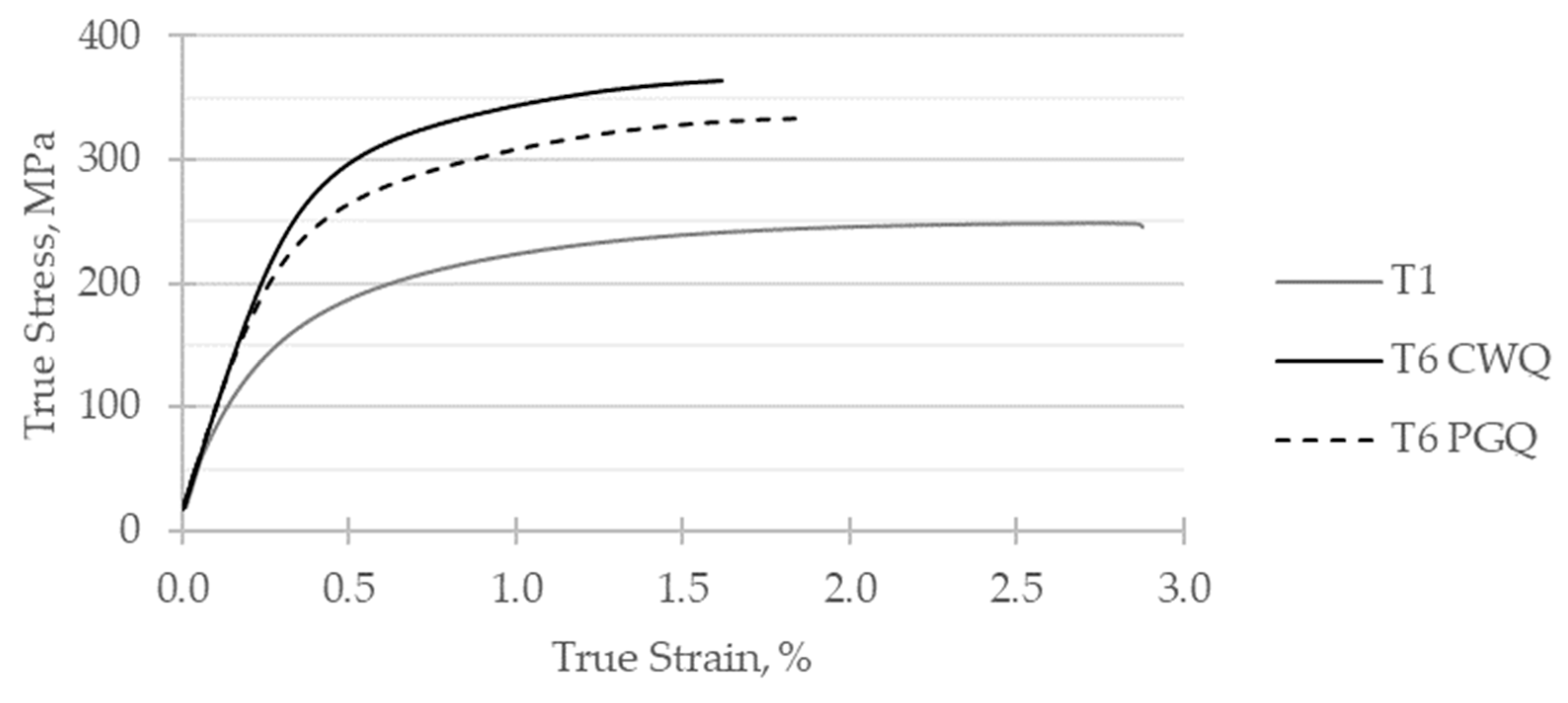
Figure 8.
Demonstration of machining process on AyontEX 17 material, highlighting ability to machine thin-wall structures and tap holes (top-right) and EDM’d 0.5mm slot (bottom-left).
Figure 8.
Demonstration of machining process on AyontEX 17 material, highlighting ability to machine thin-wall structures and tap holes (top-right) and EDM’d 0.5mm slot (bottom-left).
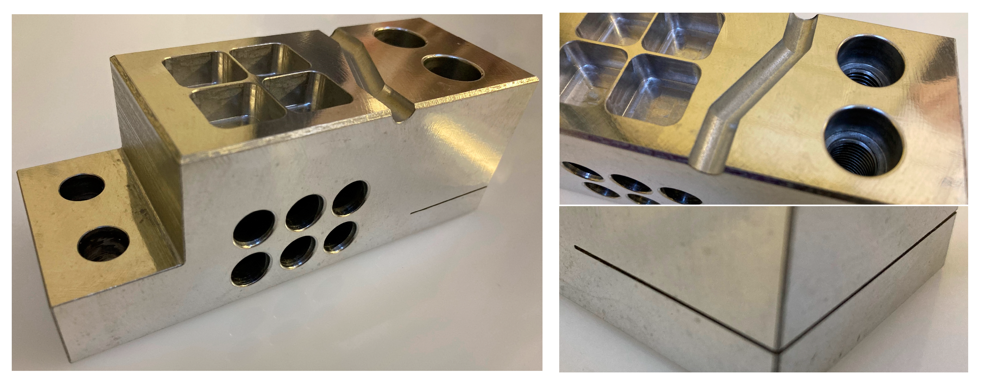
Figure 9.
Example applications of the Al-Si alloys. (a) structural heat sink manufactured in AyontEX 17. (b) optical mirror substrate manufactured in AyontEX 13.
Figure 9.
Example applications of the Al-Si alloys. (a) structural heat sink manufactured in AyontEX 17. (b) optical mirror substrate manufactured in AyontEX 13.
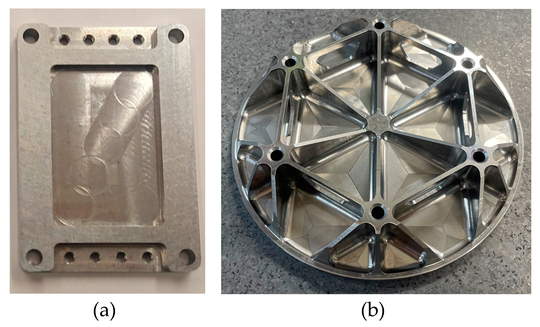
Figure 10.
Optical micrograph of AyontEX 13 with electrolytic nickel plating applied, at 500x magnification.
Figure 10.
Optical micrograph of AyontEX 13 with electrolytic nickel plating applied, at 500x magnification.
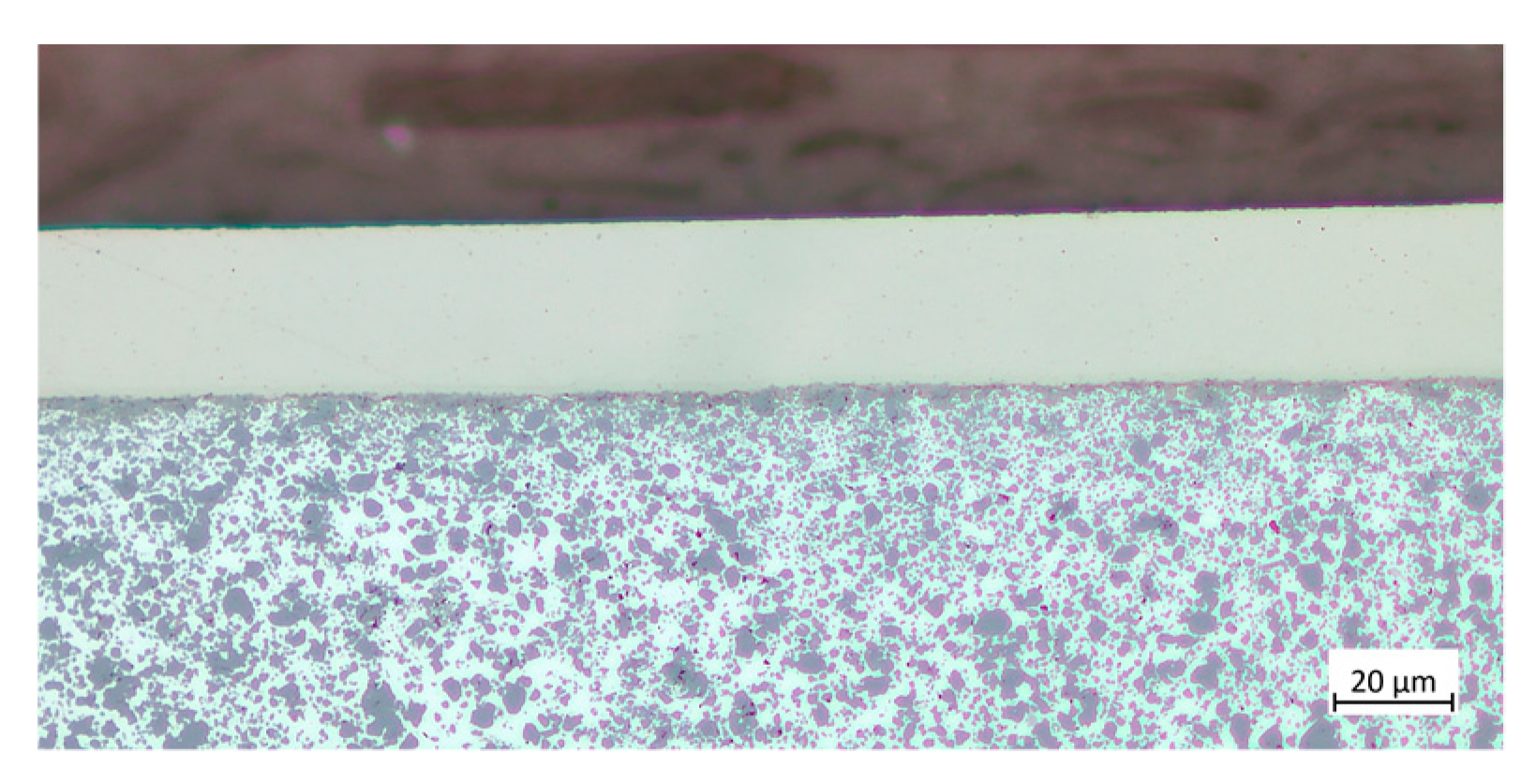
Figure 11.
Relationship between 0.2% proof strength and ultimate tensile strength versus Si vol% and heat treatment condition. (T1 = air cooled from HIP, CWQ = cold water quench).
Figure 11.
Relationship between 0.2% proof strength and ultimate tensile strength versus Si vol% and heat treatment condition. (T1 = air cooled from HIP, CWQ = cold water quench).
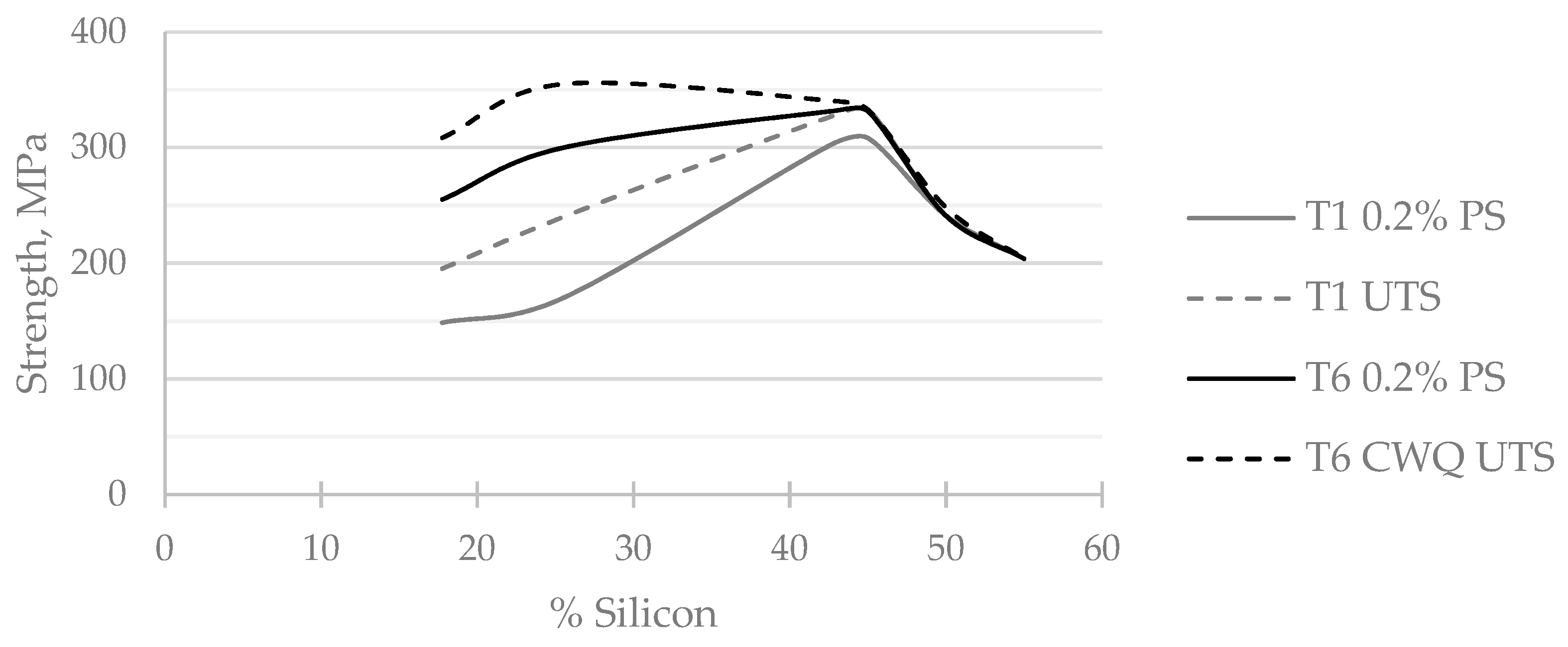

Table 1.
Summary of achieved typical properties, ranges indicate dependence on heat treatment.
| Property | Unit | AyontEX 17 | AyontEX 13 | |
|---|---|---|---|---|
| Density | g/cm3 | 2.60 | 2.54 | |
| Elastic Modulus | GPa | 87 | 103 | |
| Specific Stiffness | GPa/g/cm3 | 33 | 41 | |
| Mean CTE | (-100-20°C) | μm/(m·°C) | 15.6 | 12.1 |
| (20-50°C) | 16.8 | 13.2 | ||
| (20-100°C) | 17.2 | 13.7 | ||
| (20-200°C) | 18.4 | 14.6 | ||
| Thermal Conductivity | W/mK | 160 - 170 | 134 | |
| Specific Heat Capacity | J/g/K | 0.88 | 0.85 | |
| 0.2% Proof Strength | MPa | 170 - 300 | 300 - 340 | |
| Ultimate Tensile Strength | MPa | 240 - 355 | 325 - 345 | |
| Specific Strength | MPa/g/cm3 | 92 – 137 | 128 - 136 | |
Disclaimer/Publisher’s Note: The statements, opinions and data contained in all publications are solely those of the individual author(s) and contributor(s) and not of MDPI and/or the editor(s). MDPI and/or the editor(s) disclaim responsibility for any injury to people or property resulting from any ideas, methods, instructions or products referred to in the content. |
© 2024 by the authors. Licensee MDPI, Basel, Switzerland. This article is an open access article distributed under the terms and conditions of the Creative Commons Attribution (CC BY) license (http://creativecommons.org/licenses/by/4.0/).
Copyright: This open access article is published under a Creative Commons CC BY 4.0 license, which permit the free download, distribution, and reuse, provided that the author and preprint are cited in any reuse.


