
Submitted:
12 May 2025
Posted:
13 May 2025
You are already at the latest version
Abstract
The enhanced hard coatings with exceptional mechanical and thermal qualities has prompted substantial study into multicomponent nitride systems. TiAl(Si)N coatings have emerged as viable possibilities owing to their remarkable hardness, thermal stability, and oxidation resistance. This work involved the fabrication of thickness-varied TiAl(Si)N gradient coatings using reactive magnetron sputtering, employing a controlled modulation of aluminium and silicon content across the film thickness. Three samples, with thicknesses of ~ 400 nm, ~600 nm, and ~800 nm, were deposited under uniform Ar/N₂ gas flow ratios, and their microstructural, mechanical, and tribological characteristics were rigorously examined. SEM investigation demonstrated a significant change by thickness. XRD results validated the emergence of a predominant cubic TiAl(Si)N phase alongside a secondary hexagonal AlN phase, signifying partial phase segregation. The nanoindentation results indicated that Sample 2 exhibited the maximum hardness (~38 GPa) and Young's modulus (~550 GPa), due to an optimized equilibrium between solid solution strengthening and nanocomposite production. Tribological testing revealed that Sample 1 displayed the lowest and most consistent friction coefficient, corresponding to its superior H/E and H3/E2 ratios, which signify improved elasticity and resistance to plastic deformation. The findings emphasise that the implementation of a compositional gradient, especially in the distribution of Si and Al, markedly affects the microstructure and performance of TiAl(Si)N coatings. Gradient structures enhance microstructure, optimise hardness, and increase the friction coefficient. Ongoing refinement of gradient profiles and deposition parameters may further improve the characteristics of TiAl(Si)N coatings, facilitating their wider industrial use.
Keywords:
Multilayer coatings
; Ceramics
; Hardness
; Gradient thin films
1. Introduction
Because of the several conceivable uses in the contemporary aerospace sector, manufacturing, medicine, and so forth [1,2,3,4,5,6], multilayer nitride coatings have been extensively researched since the final quarter of the 20th century. Researchers have gathered knowledge on the deposition methods, structure, characteristics, and many application points of view from the time of the first mention of these structures to the present [3]. Binary metal nitrides were shown to have better qualities than traditional metals. Moreover, multilayer nitride coatings show great durability, wear and corrosion resistance, mechanical, optical, electrical, and magnetic qualities [7]. The particular qualities of nitride materials directly rely on their structure and kinds of chemical connections created between their constituent components [8]. This has resulted in the creation of multicomponent systems such titanium aluminium silicon nitride (TiAl(Si)N), which show better qualities than their binary equivalents [9].
Due to their outstanding qualities—high hardness, good chemical stability, and extraordinary wear and corrosion resistance—aluminum nitride (AlN) coatings have been widely used to protect metal substrates against both corrosion and wear [10,11,12]. Using magnetron sputtering, Altun et al. [10] applied single-layer AlN coatings on several Mg alloy substrates (AZ31, AZ61, AZ63, and AZ91). The findings showed that these AlN coatings really strengthened the corrosion resistance of the substrates. The anti-corrosion efficacy of the coatings, however, was much compromised by structural flaws like pinholes and fractures. Using magnetron sputtering on AZ31 Mg alloy, Wu et al. [12] created a multilayer coating made up of DLC/AlN/Al, which reduced the corrosion current density of the alloy tenfold. Using filtered cathodic vacuum arc deposition, Xie et al. [13] created composite coatings made of Al and AlN on AZ31 Mg alloy, so significantly improving substrate hardness and corrosion resistance with a hardness of 512 HV and a corrosion current density of 1.913 10-6 A/cm2. Shi et al. [14] meanwhile created a seven-structural-color AlN/Si/Al coating for Mg alloy; nevertheless, its corrosion resistance was less remarkable because of AlN layer thickness constraints. Therefore, the creation of color-tunable AlN-based hard coatings with better anti-corrosive qualities has been a constant difficulty up until now.
Designing multilayer structures is a good way to improve the corrosion resistance of coatings [15]. Of the many design techniques at hand, the trend of inserting many thin layers inside a monolayer coating to produce multilayer structural coatings has become more common [16]. The inclusion of an amorphous thin layer might hinder the development of the columnar structure in the coating, hence lowering surface flaws including pinholes and coarse clusters [16]. Zhang et al. [17], for example, deposited monolayer Hf and Hf/Si3N4 multilayer coatings on the AZ91D Mg alloy. The results showed that the implanted Si3N4 thin layers efficiently controlled the columnar development of the Hf sublayer, hence lowering coating porosity and so preventing the entrance of the corrosive medium, which increased the corrosion resistance of the Hf coating. Given the above results, including several thin layers of Si inside the AlN monolayer coating provides two advantages. The Si thin layers can reduce the columnar development of the AlN coating and lower growth-related flaws, hence improving its corrosion resistance [17]. Conversely, the Si thin layer can act as a light-reflecting surface, generating a thin film interference effect with the AlN top layer and hence generating a structural colour effect [14].
Especially at high electron density, the great incompressibility of transition metal atoms from group IVB-VIB allows them to create very orientated covalent compounds with lighter elements including C or N. When applied as coatings, such materials show remarkable mechanical qualities with great bond strength, hardness, and wear resistance [18]. While adding carbon lowers friction coefficients, introducing aluminium into ceramic TiN coatings improves thermal stability and corrosion resistance. Quaternary composite coatings produced by adding both aluminium and carbon to the TiN system outperform in wear resistance, corrosion resistance, and tribological characteristics [21,22].
Adding aluminium (Al) to TiN creates TiAlN, which enhances oxidation resistance by generating a protective Al₂O₃ layer at higher temperatures. Adding more silicon (Si) causes a nanocomposite structure in which nanocrystalline (Ti, Al)N grains are buried inside an amorphous Si₃N₄ matrix. The coating’s improved hardness and thermal stability come from its unusual design. Researches have shown that TiAl(Si)N coatings with ideal Si concentration may approach 40 GPa in hardness, far more than TiN or TiAlN coatings by itself [9].
Researchers have looked at the idea of compositional gradients inside the coating to improve even more the performance of TiAl(Si)N coatings. Functionally graded materials (FGMs) are defined by a progressive change in composition and structure across their volume, therefore producing commensurate variations in their characteristics. Regarding TiAl(Si)N coatings, a gradient in Si content may be designed to maximise the distribution of hardness, residual stress, and thermal stability over the coating thickness [23,24,25].
Compared to their homogeneous equivalents, gradient TiAl(Si)N coatings have shown better mechanical qualities. Coatings with a Si content gradient, for example, show better substrate adherence, lower residual stresses, and higher fracture propagation resistance. In applications with cyclic loads and high-temperature settings, such as cutting tools and aerospace components, these qualities are especially advantageous [26,27].
Usually, gradient TiAl(Si)N coatings are deposited using sophisticated physical vapour deposition (PVD) methods like reactive magnetron sputtering. The coating’s composition throughout its thickness may be tailored by exactly regulating the power given to the Ti, Al, and Si targets during the deposition process. Coatings with a regulated gradient in Si concentration may be made using this method, hence optimising their thermal and mechanical qualities. Recent research has underlined the benefits of gradient TiAl(Si)N coatings in several uses. Coatings with a Si content gradient, for instance, have demonstrated improved performance in high-speed machining processes where they offer longer tool life and greater wear resistance than traditional coatings. These coatings also show better oxidation resistance at high temperatures, which qualifies them for usage in severe conditions [25,28,29].
Reactive magnetron sputtering was used to successfully create TiAl(Si)N gradient coatings of different thicknesses, hence showing the effect of compositional gradients on coating performance. As far as we know, it is the first study by the change of thickness to examine structural and mechanical characteristics of TiAl(Si)N gradient coatings.
2. Materials and Methods
Magnetron Sputtering. Reactive magnetron sputtering produced TiAl(Si)N gradient coatings with the experimental configuration and consequent multilayer structure shown in Figure 1. Under a 70% Ar / 30% N₂ environment at 5 mTorr, three sputtering targets—Si₃N₄, Al, and Ti—are arranged around a rotating substrate holder (10 rpm) in Figure 1a. Pure Ar was used to deposit initially pure Ti layer. Rotational motion guarantees consistent exposure to the fluxes from every target, hence producing a steady compositional change inside the coating. Varying power supplied to magnetrons produced the gradient structure. Table 1 provides the comprehensive information.
Starting with the substrate with pure Ti, followed by TiN, and going via a progressive rise of Al content, the schematic structure of the multilayer coating is depicted in Figure 1b, ultimately reaching TiAlSiN at the top. To investigate how film thickness and gradient architecture affect coating performance, three samples with total thicknesses of 400 nm, 600 nm, and 800 nm were created. The observable colour variations in the diagram correlate to changes in composition and phase, hence verifying the successful creation of the graded TiAl(Si)N structure.
Thin films characterization. Dual-beam scanning electron microscopy (Helios 5 CX, ThermoFisher, USA) with an energy dispersive X-ray spectroscopy (EDS) equipment from EDAX (USA) for elemental analysis was used to investigate the morphology and nanostructure of the produced sensors. Using a Rigaku SmartLab diffractometer with a Cu K\u03b1 radiation source (Japan), low-angle X-ray diffraction (XRD) was used to examine the phase composition of thickness-varied TiAl(Si)N gradient thin films.
Under the following conditions—a radius of 3.00 mm, a sliding speed of 5.00 cm/s, and an applied normal load of 1.00 N—the tribological characteristics were assessed using a "ball–disk" setup on a TRB3 tribometer (Anton Paar Srl, Buchs, Switzerland). Using a "Fischerscope HM2000 S" device (Helmut Fischer GmbH, Sindelfingen, Germany), microhardness and elastic modulus were calculated under the following conditions: load ramp-up to 10.000 mN over 15 seconds and a creep duration of 5.0 seconds at the maximum load.
3. Results and Discussion
The SEM pictures in Figure 2 provide information on the microstructure and morphology of TiAl(Si)N gradient thin films produced by reactive magnetron sputtering. The gradient design was accomplished by progressively raising the aluminium content and adding silicon in the top layers throughout three samples (Sample 1: a, b, g; Sample 2: c, d, h; Sample 3: e, f, i). The surface SEM pictures (a–f) show an obvious topographical evolution: Probably because of tensile stress and the lack of Al and Si in deeper layers, Sample 1 displays microcracks and fine-grained nanocrystalline islands. By comparison, Sample 2 has faceted grains and better homogeneity ascribed to higher Al concentration and longer deposition durations. With big pyramidal grains and a dense, organised surface structure, Sample 3 has the most sophisticated morphology, benefiting from longer deposition durations and a high Al/Si composition.
From around 500 nm to about 800 nm, the cross-sectional SEM images (g-i) reveal thick, densely well-adhered columnar formations for all coatings. While Samples 2 (h) and 2 (i) exhibit more obvious columnar development with somewhat broader columns, suggesting a shift towards a more textured microstructure, Sample 2 (g) shows a finer and more compact columnar morphology. The compositional gradient and customised sputtering settings mostly drive the observed microstructural change. Higher Si concentration in the higher layers helps to create a nanocomposite structure—TiAlN nanocrystals set in an amorphous Si3N4 matrix—which impedes grain development and enhances thermal and mechanical stability. At the same time, larger nonacrystalls contain more aluminium. While steady nitridation is guaranteed by continuous gas flow ratios (30% N2 and 70% Ar), longer deposition times allow thicker, more ordered layers.
Illustrating the elements distribution of nitrogen (N), aluminium (Al), silicon (Si), and titanium (Ti) over the film thickness, Figure 2j presents the cross-sectional SEM picture of Sample 3 with a matching EDS line scan. All element’s smooth and continuous profiles verify a uniform distribution over the film, suggestive of steady co-sputtering deposition circumstances. The slight elemental gradients imply that the film is chemically homogenous without clear layering or phase separation.

Table 2.
The element composition assessed by EDS.
| Sample 1 | Element | Weight % | Atomic % | Error % |
| N K | 23.3 | 39.8 | 13.3 | |
| Al K | 31.3 | 27.8 | 8.9 | |
| Si K | 27.6 | 23.5 | 5.9 | |
| Ti K | 17.8 | 8.9 | 2.9 | |
| Sample 2 | Element | Weight % | Atomic % | Error % |
| N K | 27.2 | 45.4 | 15.0 | |
| Al K | 25 | 21.7 | 7.4 | |
| Si K | 28.2 | 23.4 | 4.9 | |
| Ti K | 19.6 | 9.5 | 3.1 | |
| Sample 3 | Element | Weight % | Atomic % | Error % |
| N K | 30.4 | 48.9 | 15.5 | |
| Al K | 21.0 | 17.5 | 8.3 | |
| Si K | 32.3 | 25.9 | 5.7 | |
| Ti K | 16.3 | 7.7 | 2.9 |
The EDS quantification backed by the spectrum in Figure 2k reveals once more the existence of the four essential components. With matching weight percentages of 27.2 wt.%, 25.0 wt.%, 28.2 wt.%, and 19.6 wt.%, respectively, Sample 2’s atomic concentrations—most likely depicted in this figure—are around 45.4 at.% N, 21.7 at.% Al, 23.4 at.% Si, and 9.5 at.% Ti. These numbers indicate a compositionally balanced quaternary nitride coating; the high nitrogen content implies total nitridation; the Al and Si are present in about equal amounts to control the microstructure and oxidation resistance. Being the densest element in the system, Ti makes a lesser atomic fraction but greatly adds to the total mass.
A purposeful change of sputtering power or target design to provide compositional tailoring is suggested by the rising nitrogen and silicon concentration from Sample 1 to Sample 3 and falling titanium content. Such changes immediately affect characteristics including heat stability, stress relaxation, and hardness. The EDS measurements’ modest error margins—mostly under 10%--confirm the dependability of the compositional data.
All things considered, the EDS quantification and Figure 2j,k together confirm the successful production of a chemically homogeneous and compositionally tailored TiAlSiN coating. These findings support the morphological data (Figure 2g–i), suggesting that the exact elemental composition of the films strongly links microstructural development.
Across all three samples, the X-ray diffraction (XRD) patterns of Samples 1, 2, and 3 verify the development of a multiphase structure comprising a primary cubic TiAl(Si)N phase and a secondary hexagonal w-AlN (ICDD card No. 00-025-1133). Described by Ji et al. in [9], the TiAl(Si)N solid solution’s (220) reflection corresponds to the dominant peak at about 61° 2θ. Extra peaks matching the (110), (103), and (200) planes of hexagonal AlN point to phase segregation, in which excess aluminium crystallises independently. The uniform XRD patterns for every sample indicate comparable phase compositions with different structural refinement.
Presented in Figure 3b, the tribological behaviour reveals the change in friction coefficients as a function of sliding distance. Initially, the coated samples show greater friction coefficients than the substrate; these rise with sliding distance. Of the coatings, Sample 1 shows the lowest and most consistent friction coefficient across the whole sliding distance, suggesting better wear resistance. By comparison, Samples 2 and 3 have more variable and greater friction coefficients, implying a progressive tribolayer deterioration during sliding. These findings draw attention to the fact that the tribological performance is closely related to the structural integrity and mechanical properties of the coating.
Figure 3c summarises the mechanical characteristics assessed by nanoindentation. Among the tested coatings, Sample 2 shows the greatest hardness (~38 GPa) and Young’s modulus (~550 GPa); Samples 1 and 3 show marginally lower values. An optimal mix between solid solution strengthening from Al and Si doping and microstructural refinement could explain Sample 2’s increase in hardness and stiffness. Excessive Al or Si segregation could cause Sample 3 to have relatively lower hardness as it would produce a softer composite structure.
Figure 3d shows the ratios of H/E and H3/E2, which respectively indicate a coating’s resistance to elastic strain and plastic deformation. Sample 1, which is in line with its better friction performance, shows the highest H/E and H3/E2 values implying the best mix of elasticity and resistance to plastic deformation. Lower H/E and H3/E2ratios are seen in Samples 2 and 3, which correspond to their greater friction coefficients and imply that although higher hardness, they are more susceptible to brittle failure under mechanical stress. All things considered, the total structural, tribological, and mechanical findings show that among the three samples, Sample 1 offers the greatest balance between hardness, elasticity, and wear resistance.
4. Conclusions
Reactive magnetron sputtering was used to synthesis TiAl(Si)N gradient coatings with different thicknesses, therefore showing the effect of compositional gradients on coating performance. As the aluminium and silicon concentration rose, the coatings showed a distinct change in surface morphology and microstructure from cracked, fine-grained structures to dense, faceted pyramidal grains. XRD study revealed a major cubic TiAl(Si)N solid solution with secondary hexagonal AlN, suggesting little phase segregation at greater Al concentrations. Mechanical tests showed that Sample 2, with an intermediate thickness, had the greatest hardness and Young’s modulus, implying an ideal balance between nanocrystallite creation and amorphous phase dispersion. Though its hardness is lower, Sample 1 showed the greatest wear resistance as assessed by friction coefficient measurements, probably because of its better elasticity and greater H/E and H3/E2 ratios. The findings underline that wear resistance is not only determined by hardness; rather, a combination of great elasticity and resistance to plastic deformation is absolutely vital. By customising microstructure and stress distribution, the research underlines that engineering compositional gradients inside TiAl(Si)N coatings can greatly improve mechanical stability and wear performance, as well as control over thickness of gradient structures. Particularly in settings needing high hardness, thermal stability, these results open the way for the further evolution of functionally graded TiAl(Si)N coatings for demanding industrial uses.
Author Contributions
Conceptualization, A. K., A. M., R. K.; methodology, A. S.; investigation, A. K., A. M., R. K. A.S.; writing—original draft preparation, A. K., A. M., R. K.; and editing, G. U.; All authors have read and agreed to the published version of the manuscript.
Funding
This research has been funded by the Science Committee of the Ministry of Science and Higher Education of the Republic of Kazakhstan (Grant No. AP22684071 “Novel high hardness, corrosion- and wear-resistant TiAlN/Si multilayer coatings”).
Informed Consent Statement
Not applicable.
Data Availability Statement
The data sets supporting the results of this article are included with-in.the article.
Acknowledgments
The authors would like to express their sincere gratitude to Professor Alexander Pogrebnjak and Dr. Amanzhol Turlybekuly for their valuable guidance, scientific insight, and continuous support throughout this research. Their expertise and dedication significantly contributed to the successful completion of this work.
Conflicts of Interest
The authors declare no conflicts of interest.
References
- Sagdoldina, Z.; Rakhadilov, B.; Kurbanbekov, S.; Kozhanova, R.; Kengesbekov, A. Effect of Irradiation with Si+ Ions on Phase Transformations in Ti–Al System during Thermal Annealing. Coatings 2021, 11, 205. [Google Scholar] [CrossRef]
- Rakhadilov, B.K.; Kenesbekov, A.B.; Kowalevski, P.; Ocheredko, Y.A.; Sagdoldina, Zh.B. DEVELOPMENT OF AIR-PLASMA TECHNOLOGY FOR HARDENING CUTTING TOOLS BY APPLYING WEAR-RESISTANT COATINGS. NEWS of National Academy of Sciences of the Republic of Kazakhstan 2020, 3, 54–62. [Google Scholar] [CrossRef]
- Zhang, X.; Zeng, Z.; Zeng, X.; Pelenovich, V.; Wan, Q.; Pogrebnjak, A.; Xue, L.; Chen, Y.; Yang, B. Hardening Mechanism and Plastic Deformation Behavior in Super-Hard AlCrNbSiTiN High-Entropy Nitride Nanocomposite Coatings. Mater Res Lett 2025, 13, 103–112. [Google Scholar] [CrossRef]
- Azamatov, B.; Dzhes, A.; Borisov, A.; Kaliyev, D.; Maratuly, B.; Sagidugumar, A.; Alexandr, M.; Turlybekuly, A.; Plotnikov, S. Antibacterial Properties of Copper-Tantalum Thin Films: The Impact of Copper Content and Thermal Treatment on Implant Coatings. Heliyon 2025, 11, e41130. [Google Scholar] [CrossRef]
- Kasymbaev, A.; Smirnova, K.; Pogrebnyak, A. PHYSICAL PATTERNS OF OBTAINING WN/ZrN COMPOSITE COATINGS BY THE METHOD OF VACUUM ARC DEPOSITION. Bulletin of Shakarim University. Technical Sciences 2024, 1, 462–470. [Google Scholar] [CrossRef]
- Pogrebnyak, A.D.; Ivashchenko, V.I.; Erdybaeva, N.K.; Kupchishin, A.I.; Lisovenko, M.A. Microstructure and Mechanical Properties of Multilayer α-AlN/α-BCN Coating as Functions of the Current Density during Sputtering of a B4C Target. Physics of the Solid State 2018, 60, 2030–2033. [Google Scholar] [CrossRef]
- Vereschaka, A.; Tabakov, V.; Grigoriev, S.; Sitnikov, N.; Oganyan, G.; Andreev, N.; Milovich, F. Investigation of Wear Dynamics for Cutting Tools with Multilayer Composite Nanostructured Coatings in Turning Constructional Steel. Wear 2019, 420–421, 17–37. [Google Scholar] [CrossRef]
- Maksakova, O.V.; Simoẽs, S.; Pogrebnjak, A.D.; Bondar, O.V.; Kravchenko, Ya.O.; Koltunowicz, T.N.; Shaimardanov, Zh.K. Multilayered ZrN/CrN Coatings with Enhanced Thermal and Mechanical Properties. J Alloys Compd 2019, 776, 679–690. [Google Scholar] [CrossRef]
- Ji, L.; Liu, H.; Huang, C.; Li, S.; Yin, M.; Liu, Z.; Zhao, J.; Xu, L. Effect of TiAlSiN Gradient Structure Design on Mechanical Properties and Microstructure of Coatings. Surf Coat Technol 2025, 496, 131617. [Google Scholar] [CrossRef]
- Altun, H.; Sen, S. The Effect of DC Magnetron Sputtering AlN Coatings on the Corrosion Behaviour of Magnesium Alloys. Surf Coat Technol 2005, 197, 193–200. [Google Scholar] [CrossRef]
- Altun, H.; Sen, S. The Effect of PVD Coatings on the Corrosion Behaviour of AZ91 Magnesium Alloy. Mater Des 2006, 27, 1174–1179. [Google Scholar] [CrossRef]
- Wu, G.; Dai, W.; Zheng, H.; Wang, A. Improving Wear Resistance and Corrosion Resistance of AZ31 Magnesium Alloy by DLC/AlN/Al Coating. Surf Coat Technol 2010, 205, 2067–2073. [Google Scholar] [CrossRef]
- Xie, W.; Zhao, Y.; Liao, B.; Pang, P.; Wuu, D.; Zhang, S. Al–AlN Composite Coatings on AZ31 Magnesium Alloy for Surface Hardening and Corrosion Resistance. Vacuum 2021, 188, 110146. [Google Scholar] [CrossRef]
- Shi, X.; Zhang, S.; You, Y.; Sun, D.; Yu, X.; Wang, J.; Du, H.; Li, F. Enhancing Color Tunability, Corrosion Resistance, and Hardness of AlN/Al Coatings on Magnesium Alloys via Sputtering a Si Interlayer. Vacuum 2023, 209, 111772. [Google Scholar] [CrossRef]
- Wan, Z.; Zhang, T.F.; Lee, H.-B.-R.; Yang, J.H.; Choi, W.C.; Han, B.; Kim, K.H.; Kwon, S.-H. Improved Corrosion Resistance and Mechanical Properties of CrN Hard Coatings with an Atomic Layer Deposited Al 2 O 3 Interlayer. ACS Appl Mater Interfaces 2015, 7, 26716–26725. [Google Scholar] [CrossRef]
- Zhang, D.; Qi, Z.; Wei, B.; Shen, H.; Wang, Z. Microstructure and Corrosion Behaviors of Conductive Hf/HfN Multilayer Coatings on Magnesium Alloys. Ceram Int 2018, 44, 9958–9966. [Google Scholar] [CrossRef]
- Zhang, D.; Qi, Z.; Wei, B.; Wu, Z.; Wang, Z. Anticorrosive yet Conductive Hf/Si 3 N 4 Multilayer Coatings on AZ91D Magnesium Alloy by Magnetron Sputtering. Surf Coat Technol 2017, 309, 12–20. [Google Scholar] [CrossRef]
- Zhou, B.; Wang, Y.; Liu, Z.; Zhi, J.; Sun, H.; Wang, Y.; Wu, Y.; Hei, H.; Yu, S. Effect of Modulation Ratio on Microstructure and Tribological Properties of TiAlN/TiAlCN Multilayer Coatings Prepared by Multi-Excitation Source Plasma. Vacuum 2023, 211, 111917. [Google Scholar] [CrossRef]
- Zeng, Y.; Qiu, Y.; Mao, X.; Tan, S.; Tan, Z.; Zhang, X.; Chen, J.; Jiang, J. Superhard TiAlCN Coatings Prepared by Radio Frequency Magnetron Sputtering. Thin Solid Films 2015, 584, 283–288. [Google Scholar] [CrossRef]
- Yeung, M.T.; Lei, J.; Mohammadi, R.; Turner, C.L.; Wang, Y.; Tolbert, S.H.; Kaner, R.B. Superhard Monoborides: Hardness Enhancement through Alloying in W 1− x Ta x B. Advanced Materials 2016, 28, 6993–6998. [Google Scholar] [CrossRef]
- Tillmann, W.; Grisales, D.; Marin Tovar, C.; Contreras, E.; Apel, D.; Nienhaus, A.; Stangier, D.; Lopes Dias, N.F. Tribological Behaviour of Low Carbon-Containing TiAlCN Coatings Deposited by Hybrid (DCMS/HiPIMS) Technique. Tribol Int 2020, 151, 106528. [Google Scholar] [CrossRef]
- Liu, K.; Ma, F.; Lou, M.; Dong, M.; Zhu, Y.; Wang, Y.; Wu, X.; Liu, X.; Li, J. Structure and Tribocorrosion Behavior of TiAlCN Coatings with Different Al Contents in Artificial Seawater by Multi-Arc Ion Plating. Surf Topogr 2021, 9, 045004. [Google Scholar] [CrossRef]
- Qin, B.; Sun, Q.; Yu, J.; Wen, T. Strength Variation and Cracking Behavior of Corundum Bricks with Modified Hydrated Magnesium Chloride Binders. Ceram Int 2024, 50, 23568–23576. [Google Scholar] [CrossRef]
- Lungu, M.V.; Tălpeanu, D.; Ciobanu, R.C.; Cojocaru, A.; Pătroi, D.; Marinescu, V.; Caramitu, A.R. Evaluation of Magnetron Sputtered TiAlSiN-Based Thin Films as Protective Coatings for Tool Steel Surfaces 2024.
- Oda, A.; Kinoshita, K.; Yoda, S.; Katsumata, H.; Uekusa, S. Growth of Si0.5Ge0.5 Single Crystals by the Traveling Liquidus-Zone Method and Their Structural Characterization. Procedia Eng 2012, 36, 404–410. [Google Scholar] [CrossRef]
- Lü, W.; Li, G.; Zhou, Y.; Liu, S.; Wang, K.; Wang, Q. Effect of High Hardness and Adhesion of Gradient TiAlSiN Coating on Cutting Performance of Titanium Alloy. J Alloys Compd 2020, 820, 153137. [Google Scholar] [CrossRef]
- Su, K.; Liu, D.; Shao, T. Microstructure and Mechanical Properties of TiAlSiN Nano-Composite Coatings Deposited by Ion Beam Assisted Deposition. Sci China Technol Sci 2015, 58, 1682–1688. [Google Scholar] [CrossRef]
- Zhou, Q.; Huang, B.; Zhang, E.; Peng, Z.; Chen, Q.; Liang, D. Improving the Mechanical and Tribological Properties of TiAlSiN Coatings by Annealing. Vacuum 2023, 214, 112249. [Google Scholar] [CrossRef]
- Dauphas, S.; Ababou-Girard, S.; Girard, A.; Le Bihan, F.; Mohammed-Brahim, T.; Vié, V.; Corlu, A.; Guguen-Guillouzo, C.; Lavastre, O.; Geneste, F. Stepwise Functionalization of SiNx Surfaces for Covalent Immobilization of Antibodies. Thin Solid Films 2009, 517, 6016–6022. [Google Scholar] [CrossRef]
Figure 1.
The schematic illustration of the reactive magnetron sputtering process, and composition of the thickness-varied TiAl(Si)N gradient thin films.
Figure 1.
The schematic illustration of the reactive magnetron sputtering process, and composition of the thickness-varied TiAl(Si)N gradient thin films.
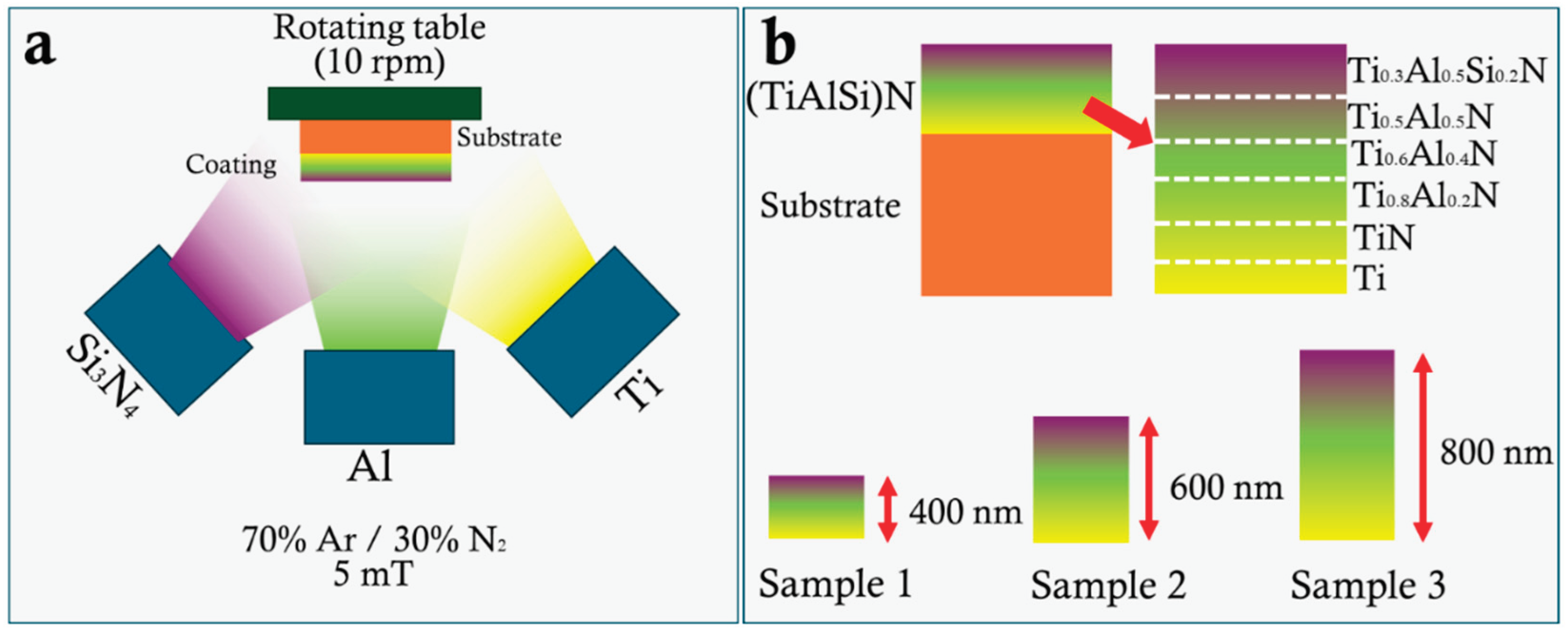
Figure 2.
The surface and cross-sectional morphology of the thickness-varied TiAl(Si)N gradient thin films(Sample 1: a, b, g; Sample 2: c, d, h; Sample 3: e, f, i); j, k)The cross-section with elements distribution by line and EDS spectra for the Sample 3.
Figure 2.
The surface and cross-sectional morphology of the thickness-varied TiAl(Si)N gradient thin films(Sample 1: a, b, g; Sample 2: c, d, h; Sample 3: e, f, i); j, k)The cross-section with elements distribution by line and EDS spectra for the Sample 3.
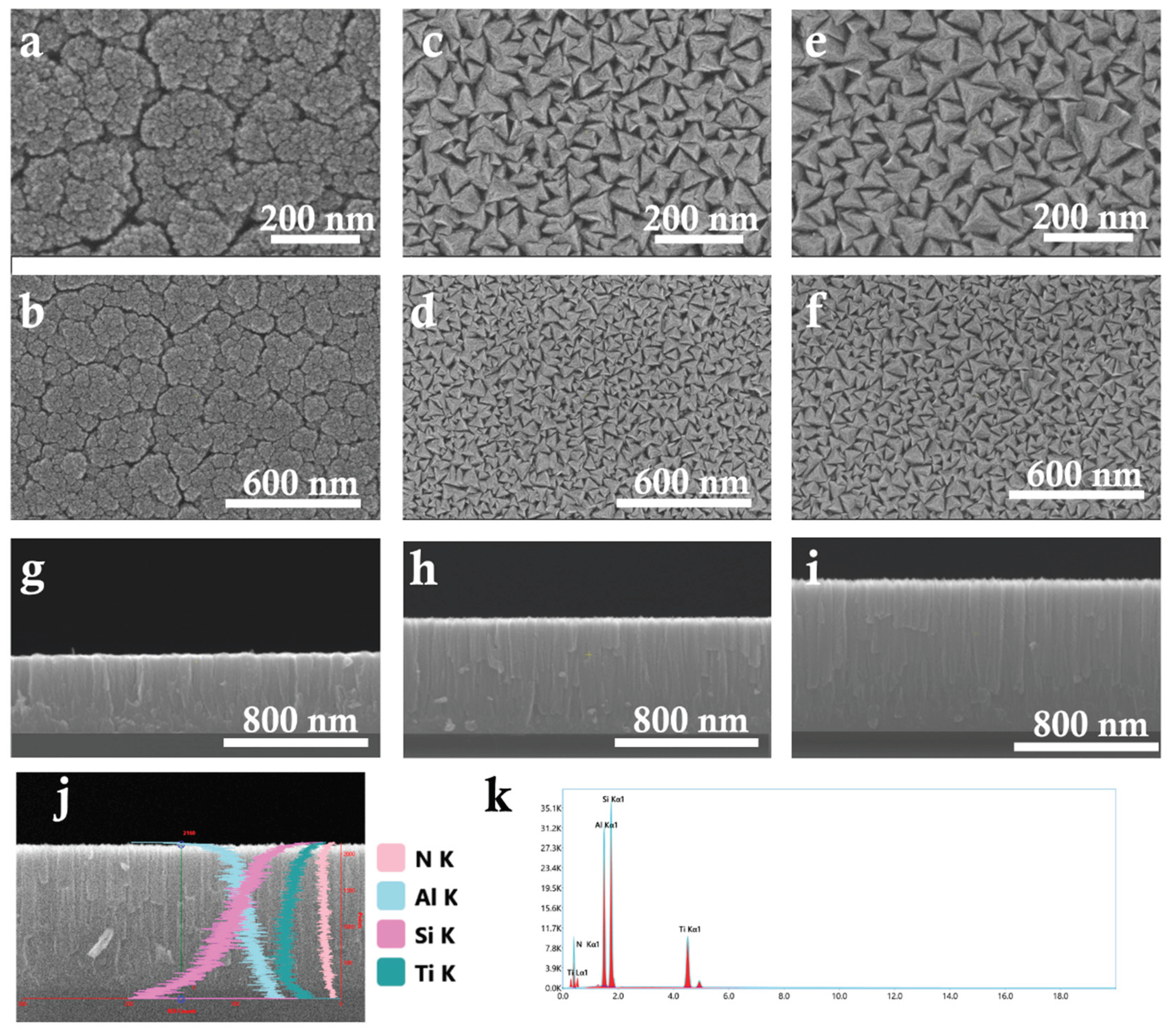
Figure 3.
The structural and mechanical characterization of the thickness-varied TiAl(Si)N gradient thin films: a) XRD patterns; b) Tribological testing; c) hardness and Young modulus; d) H/E and H3/E2.
Figure 3.
The structural and mechanical characterization of the thickness-varied TiAl(Si)N gradient thin films: a) XRD patterns; b) Tribological testing; c) hardness and Young modulus; d) H/E and H3/E2.
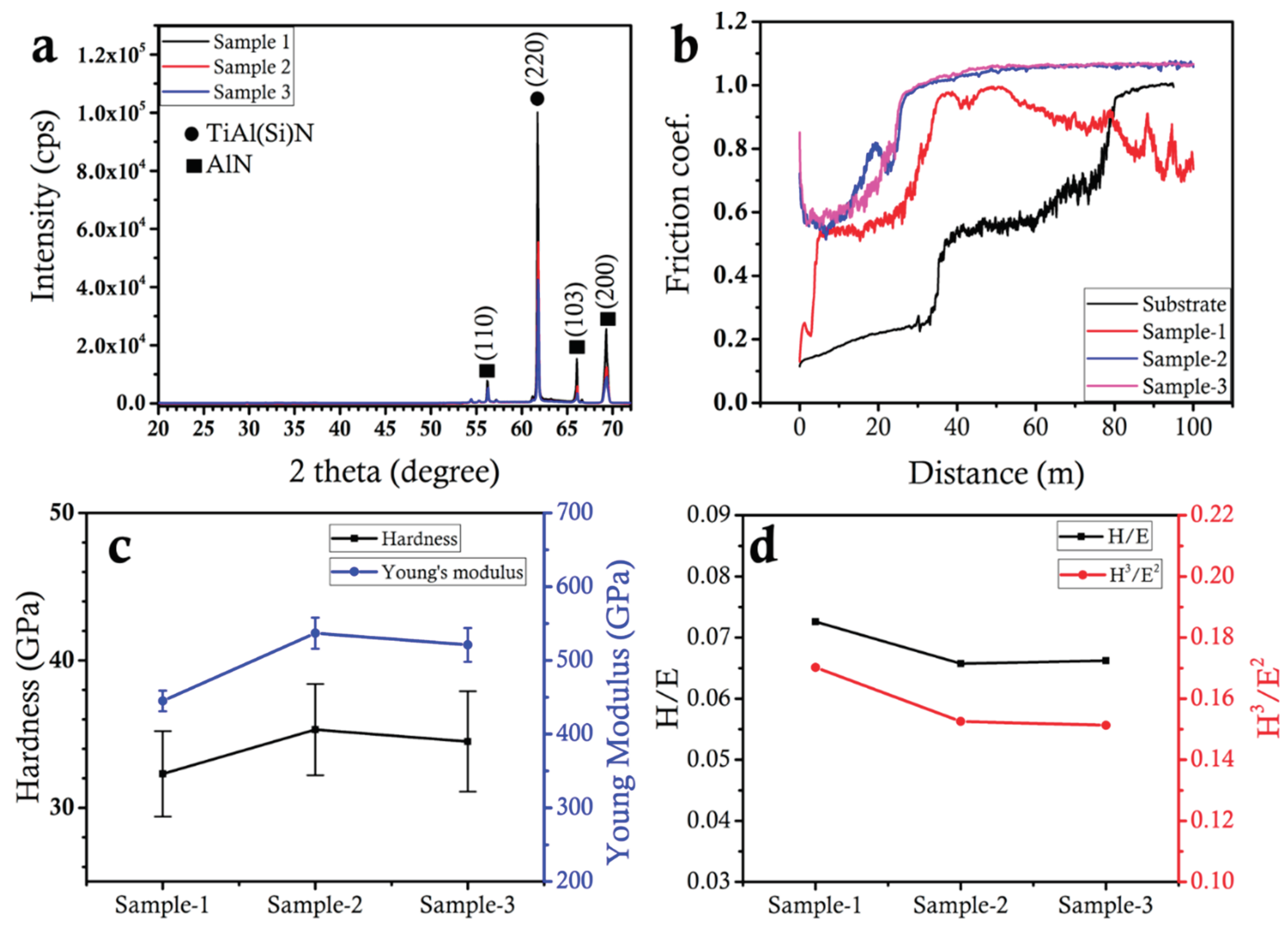
Table 1.
Deposition parameters.
| Sample 1 | Layer 1, time 15 min | Layer 2, time 15 min | Layer 3, time 15 min | Layer 4, time 20 min | Layer 5, time 20 min | Layer 6, time 20 min | |
| Ti, Watt | 100 | 100 | 100 | 100 | 100 | 100 | |
| Al, Watt | 0 | 0 | 10 | 20 | 30 | 30 | |
| Si, Watt | 0 | 0 | 0 | 0 | 0 | 75 | |
| N2, % | 0 | 30 | 30 | 30 | 30 | 30 | |
| Ar, % | 100 | 70 | 70 | 70 | 70 | 70 | |
| Sample 2 | Layer 1, time 15 min | Layer 2, time 25 min | Layer 3, time 25 min | Layer 4, time 25 min | Layer 5, time 25 min | Layer 6, time 25 min | |
| Ti, Watt | 100 | 100 | 100 | 100 | 100 | 100 | |
| Al, Watt | 0 | 0 | 10 | 20 | 30 | 30 | |
| Si, Watt | 0 | 0 | 0 | 0 | 0 | 75 | |
| N2, % | 0 | 30 | 30 | 30 | 30 | 30 | |
| Ar, % | 100 | 70 | 70 | 70 | 70 | 70 | |
| Sample 3 | Layer 1, time 15 min | Layer 2, time 35 min | Layer 3, time 35 min | Layer 4, time 35 min | Layer 5, time 35 min | Layer 6, time 35 min | |
| Ti, Watt | 100 | 100 | 100 | 100 | 100 | 100 | |
| Al, Watt | 0 | 0 | 10 | 20 | 30 | 30 | |
| Si, Watt | 0 | 0 | 0 | 0 | 0 | 75 | |
| N2, % | 0 | 30 | 30 | 30 | 30 | 30 | |
| Ar, % | 100 | 70 | 70 | 70 | 70 | 70 |
Disclaimer/Publisher’s Note: The statements, opinions and data contained in all publications are solely those of the individual author(s) and contributor(s) and not of MDPI and/or the editor(s). MDPI and/or the editor(s) disclaim responsibility for any injury to people or property resulting from any ideas, methods, instructions or products referred to in the content. |
© 2025 by the authors. Licensee MDPI, Basel, Switzerland. This article is an open access article distributed under the terms and conditions of the Creative Commons Attribution (CC BY) license (http://creativecommons.org/licenses/by/4.0/).
Copyright: This open access article is published under a Creative Commons CC BY 4.0 license, which permit the free download, distribution, and reuse, provided that the author and preprint are cited in any reuse.


