Submitted:
10 April 2024
Posted:
11 April 2024
You are already at the latest version
Abstract
Recent experiments devoted to characterizing the behavior of sessile ferroelectric liquid droplets on ferroelectric solid substrates, showed the existence of a droplet electromechanical Rayleigh-like instability. The instability is induced by the bulk polarization of the ferroelectric fluid which couples to the polarization of the underlying substrate through its fringing field and solid-fluid interface coupling. With the aim of characterizing this phenomenon, namely the coupling between the polarizations of a fluid and a solid material, we studied the behavior of ferroelectric liquid droplets confined between two solid substrates, arranged in different configurations realized so to generate fringing fields with different profiles. Results show that the features of the droplets instability are indeed affected by the specific fringing field shape in a way dominated by the minimization of the electrostatic energy associated to the bulk polarization of the ferroelectric fluid.
Keywords:
ferroelectric nematic liquid crystals
; lithium niobate
; fringing field
; polarization coupling
1. Introduction
The discovery of the ferroelectric nematic phase [1] has been a groundbreaking event and the combination of fluidity in ferroelectric fluid and its polar coupling to electric fields is opening the gate to a whole new world of phenomena, which are rapidly becoming the focus of the liquid crystals and soft material scientific communities, as demonstrated by the large number of scholarly articles already published on the subject [2,3,4,5,6,7,8,9,10,11,12].
In this scenario, we recently performed experiments devoted to characterizing the behavior of sessile ferroelectric nematic liquid crystal droplets on ferroelectric solid substrate [4]. We observed that upon entering the ferroelectric nematic phase, droplets undergo an electromechanical instability characterized by the sudden ejection of fluid jets, which branch into smaller streams and eventually form secondary small droplets [4,13]. This behavior is analogous to the instability predicted by Lord Rayleigh for charged conductive liquid droplets that are above the critical charge-to-volume ratio [14]. In the case of the neutral ferroelectric nematic droplets this process occurs in the absence of free charges, but with the requisite charging within the droplet arising from the intrinsic polarization of the ferroelectric liquid crystal via its contact with the ferroelectric substrate. The coupling between the polarization in the solid and fluid materials is mediated by the fringing field generated by the pyroelectric charging of the substrate. This polarization coupling induces the accumulation of surface charges on the droplet-air interface. As the polarization of the ferroelectric nematic grows by cooling the material, the local accumulation of polarization charges gives rise to repulsive forces that become unsustainable by the surface tension. As this condition is met, the instability turns to an explosive runaway process since the flow of the liquid ferroelectric in the nascent jet induces orientational order of the nematic director along the jet direction, which transports polarization charge to its tip in turn increasing the electrostatic repulsion.
The observed polarization-induced droplet instability crucially depends on the properties of the ferroelectric nematic phase and on the combination of polarization and fluidity unique to this system. Ferroelectric nematic liquid crystals offer for the first time the opportunity of studying the coupling between the polarization of a fluid and a solid ferroelectric, which understanding might provide the basis for novel electro-hydromechanical applications.
In this work we aim at characterizing in details the effects of the fringing field created by the ferroelectric substrate on the droplets’ instability. To this purpose, we did not work with sessile droplets but confined them between two ferroelectric substrates arranged in two different ways so to generate fringing fields with different profiles. Specifically, we realized sandwich cells where the substrates polarization vectors are parallel or antiparallel, so to develop opposite or equal surface electrostatic charges at the interfaces with the liquid crystal droplet.
Worthy of note the behavior of liquid crystalline materials in combination with photoactivable substrates has also been studied in the case of the conventional nematic phase in several different configurations [15,16]. The effect of the substrate charging on the liquid crystal average molecular orientation has been demonstrated, however no effect comparable to those observed with ferroelectric nematics was reported.
2. Materials and Methods
The ferroelectric liquid crystal used in this work is 4-[(4-nitrophenoxy)carbonyl]phenyl2,4-dimethoxybenzoate (RM734). It was synthesized as described in [1] and its structure and phase diagram have already been reported [1,2]. In this compound the ferroelectric nematic phase (NF) appears through a weakly fist order phase transition upon cooling from the conventional higher temperature nematic (N) phase and exists in the range 133 °C—80 °C [1,2]. The spontaneous polarization P of RM734 is either parallel or antiparallel to the molecular director n, defining the average orientation of the molecular axis, and exceeds 6 µC/cm2 at the lowest temperature in the NF phase [1].
As ferroelectric solid substrates we used 900 µm thick z-cut undoped lithium niobate (LN) crystals (PI-Kem). The bulk spontaneous polarization of LN crystals along the [0001] z-axis is of the order of 70 µC/cm2 and does not depend significantly on T in the explored range since its Curie temperature is much higher (≈ 1140 °C). Despite such a high bulk polarization of LN, very efficient compensation mechanisms at the z-cut surfaces lower the equilibrium surface charge to only about 10-2 µC/cm2 [17]. When temperature variations are induced, the surface charge of LN can significantly increase because of the pyroelectric effect [18,19,20], a transient phenomenon observable during and shortly after the variation [18] and due to the slow free charge relaxation in LN. The pyroelectric coefficient of undoped LN is of the order of 10-4 C/m2K at room temperature [21,22], and increases by one order of magnitude around 100 °C [23]. Given the temperature used in our experiments, dictated by the RM734 phase diagram, we can thus expect an induced surface charge density of the order of 1 µC/cm2, for T variations of a few degrees ramped in a short time compared to the LN charge relaxation. To match the conditions of the previous work on sessile droplets [4], LN crystals were used as bare substrates with no coating applied.
To prepare the samples used in this work, a RM734 droplet was deposited on a LN substrate at a temperature T = 200 °C, corresponding to the liquid crystal isotropic phase and then covered by a second LN slab previously heated at the same T. RM734 droplets were realized following two steps. First, a small amount of RM734 powder was deposited at room temperature on a clean glass slide and heated to 150 °C to have a melt. To create the initial droplets, a cold stainless needle is dipped into the melt and retracted, so that the droplet on its tip solidifies at contact with the surrounding air. To increase the size of the RM734 “pearl”, rapid (to avoid re-melting) successive dipping are performed. Then, the pearl is remolten into a droplet on the heated LN substrate. The two substrates were then stick together by means of two 125 µm thick stripes of Kapton tape, which also define the cell thickness. The liquid crystal droplet confined between two solid substrates assumes the form of a capillary bridge (Figure 1a). The entire cell was then transferred in a small, closed oven, suitable for the optical microscope and cooled down to the NF phase. In order to perform a systematic analysis of the instability events, we decreased the cell temperature by steps of 5 °C ramped in 60 s each, resulting in a cooling rate of 0.08 °C/s. Due to the structure of the used oven, the temperature variation is the same in the entire cell, which guarantees the same amount of pyroelectric charging on both of them.
The liquid crystal cells realized with two LN substrates are of two different kinds. Specifically, LN crystals were arranged so to expose equally or opposite charged surfaces at the interfaces with the liquid crystal, as sketched in Figure 1a. The two configurations will be referred to as np/pn and np/np, where n and p stay for negative and positive, respectively. Noteworthy, the large thickness of the cells (100 µm) makes the droplets volume high enough to balance the additional friction due to confinement and the much lower thermal gradients on the LN substrates due to the closed arrangement.
The details of the electromechanical droplets’ instability have been analyzed by POM observations and videos recorded by a CCD camera operating at 25 frames per second.
3. Results and Discussion
Due to the finite size of LN crystals, their pyroelectric charging gives rise to an external fringing field. This field is a fraction f of the internal field σLN/ε0, whit f depending on the crystal shape and size and has been estimated to be f ≈ 10-3 in our experimental conditions [4]. The fringing fields generated by the LN slabs combine in different ways in np/np and np/pn cells, which results in different profile and value of the total field present in the region between the substrates. The total fringing field Eff in the two cells, in the absence of the liquid crystalline fluid bridge, is reported in Figure 1. Panel a shows the normalized field E (intensity and lines) and its x and z components on the xz plane at y = 0 for the two configurations (top: np/np; bottom: np/pn). The np/pn arrangement gives rise to a total fringing field which is mainly vertical and quite uniform along the cell thickness. The x component is different from zero, although very weak, only close to the substrates corners. On the contrary, the np/pn configuration produces a total fringing field with a very weak vertical component, different from zero only at the corners, and a x component uniform along the thickness and increasing from the center to the edges of the LN plates. The vertical and in-plane field components are reported in panels b (np/np) and c (np/pn) at three different positions along the cell thickness d: z = 0, z = d/2 and z = d. For the in-plane component Et, the field lines are also shown. They are radially distributed on the xy planes. The absolute values of the field are also different in the two cells, being about 8.4 x 10⁵ V/m for the np/np cells and 3.2 x 10⁵ V/m for the np/pn ones (maximum values).
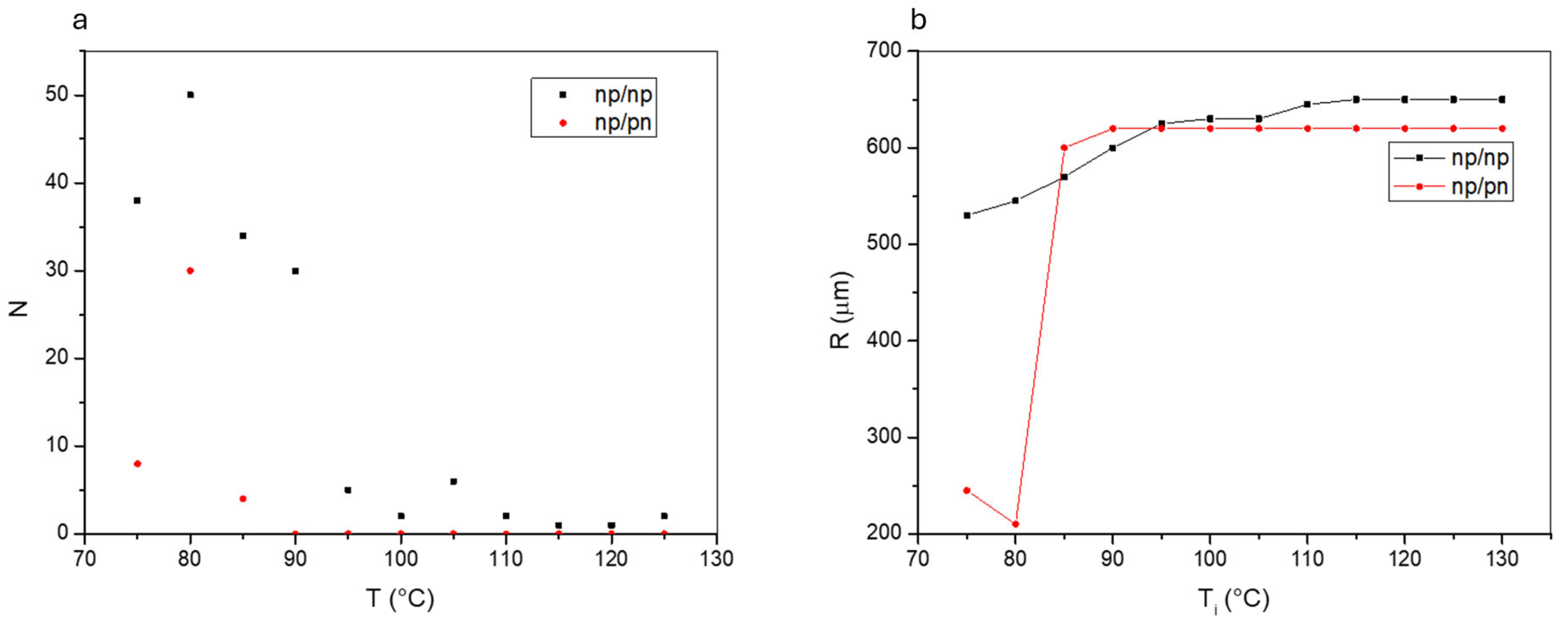
The specific profile of Eff affects the features of the electromechanical instability of the NF fluid bridge. In particular, i) the number of instability events observed within the temperature window corresponding to the NF phase, ii) the number of ejected fluid jets for each of these events and iii) the temperature at which these events start, depend on the specific substrates’ arrangement. This is shown in Figure 2 a, where the number N of observed fluid jets is reported as a function of the instability temperature Ti, defined as the temperature at which the instability event takes place. Different colors correspond to different kinds of cell. It is evident that the instability starts at higher temperature in np/np cells, which thus exhibit the highest number of instability events. Moreover, these events are on the average characterized by the highest number of ejected jets. Since higher temperature corresponds to a lower value of the NF polarization P [1], the results in Figure 2 a indicate that in np/np cells the charging threshold is reached for lower values of P than in the other kind of cell.
The np/np configuration with its mainly vertical and uniform fringing field, is similar to the geometry used by Mathe et al., in [24], where a ferroelectric fluid bridge was confined between two conductive glasses and an external electric field was applied perpendicular to the cell substrates. The instability caused by this field was interpreted as a kind of labyrinthine instability already observed both in magnetic fluid exposed to a magnetic field orthogonal to the bounding plates or in dielectric fluids [25,26,27]. In both cases, the presence of a gap that separates the fluid from the magnetic poles or from the electrodes is necessary for the instability to take place. Such a gap allows the presence of a field component parallel to the plates. In our case, the gap is intrinsically present since LN is itself an insulator.
The presence of the ferroelectric fluid bridge changes the fringing field profile reported in Figure 1. In np/np cells this change consists in the appearance of an additional component of the field parallel to the bounding surfaces. It is known that the bulk polarization of the NF liquid crystal spontaneously self organizes to minimize the internal and external electric fields. Generally, P will end up parallel to the interfaces to avoid accumulation of surface charge σ = P.u (where u is the unit vector perpendicular to the surfaces) and will adopt bend deformations which do not produce space charge, preventing nonzero ∇∙P as much as compatible with geometrical constraints. In the presence of the fringing field, which in this geometry is mainly normal to LN/NF interface planes, the ferroelectric nematic becomes polarized. This happens through a small reorientation of P by an angle such to deposit polarization charge on the fluid bridge surfaces that cancel the internal field, a peculiarity of the NF phase indicated as “fluid superscreening” [4,9]. This process leads to a mismatch between the field inside the bridge, where the potential difference is virtually negligible being the one due to the field in the thin gap between the LN charged surface and the liquid crystal interfacial layer, and the one outside, where the potential difference is the one in air. This generates an additional in plane component of the field, which can be arbitrarily large depending on the thickness of the layer along which the potential difference passes from zero to the value dσLN/ε0. The additional field component drives jet ejection from the charge accumulation sites. The result is the occurrence of several instability events, with the ejection of a large number of jets from different portions of the capillary bridge at the interfaces with the bounding plates (Figure 3a-d).
An additional feature of np/np cells is the temperature at which the instability starts, which is higher than in np/pn cells, a behavior that we ascribe to the higher value of Eff components which characterizes this specific substrates’ arrangement.
Figure 3.
Examples of the observed electromechanical instability in NF fluid bridges formed by confining a RM734 droplet between two LN crystals. a-d) Sequence of frames showing the evolution of the instability in the np/np configuration. Some of the jets are clearly ejected from locations on different planes, namely the two interface planes with the substrates; e-h) sequence of frames showing the evolution of the instability in the np/pn configuration. In this case jets rapidly grow in diameter up to involve large portions of the droplet rim and volume on both interface planes. Note that the small droplets already present in the images (Figure 3a and 3e) are due to fragmentation of the main one during sample preparation. Frames are not consecutive.
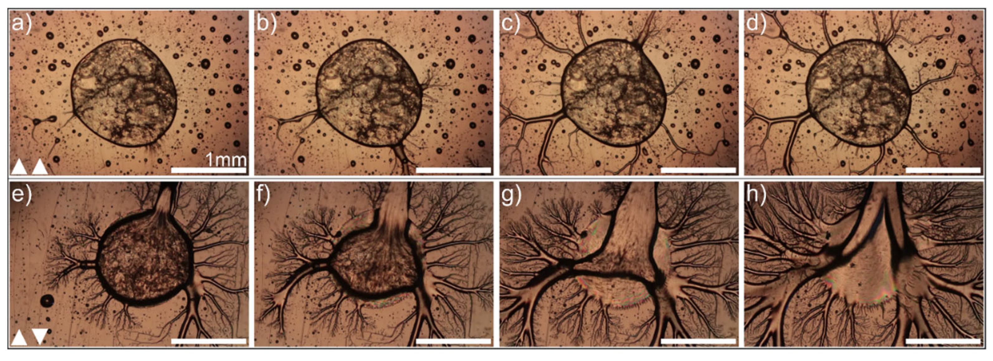
In np/pn cells the fringing field has a lower absolute value and is mostly in plane, while the vertical component is weak and practically negligible at the center of the cell; P and Eff are thus both parallel to the LN/NF interface planes and the required in plane component of the field is present from the beginning due to the specific LN substrates arrangement. In these conditions, the polarization charge that cancel the internal field are generated at the NF/air lateral interfaces through twist distortions which are compatible with P being parallel to the two bounding surfaces. This again create an additional electric field that in this case is comparable in magnitude to the original value of the fringing field. The threshold charging giving rise to the electromechanical instability is here reached for temperatures lower than in np/np cells, corresponding to higher values of P, and produce on the average the ejection of a lower number of fluid jets. We understand this phenomenon as due to the weaker fringing field that characterizes this configuration. Noteworthy, experiments on NF sessile droplets deposited on glass surfaces with patterned electrodes, showed that jet ejection preferentially occurs in regions where the fringing field is in the vertical direction [24]. This is an additional indication that the in-plane electric field component arising in these conditions due to the NF superscreening, is higher than in any other configuration.
Once jets are formed in np/pn samples, they are however more disruptive than in the other kind of cell. This is shown in Figure 2b, where the variation of the average droplet radius after each instability event is reported as a function of Ti. This parameter exhibits a decreasing trend for both configurations, but such a decreasing trend is different in the two situations, being smooth for the np-np cells and very steep for the np-pn ones. In this latter case, the average radius decreases by more than 60% after the first instability events, indicating an extremely explosive and disruptive phenomenon.
We understand this behavior as due to the radial shape of Eff in the np/pn LN arrangement. Indeed, jets are polar fluid tubes carrying polarization charges on their tips, which thus keep on moving in the direction of the field, accelerated by the field itself. On the contrary, in the np/np case, the in-plane component of the field generated by NF superscreening, changes value and direction as soon as jets protrude from the bridge bounding plates since it depends on the position of the polarization charges. In this case there is not a “constant” radial field able to move the charged expelled fluid along its direction.
The observed disruptive instability in np/pn cells might additionally be due to the acceleration experienced by the jets’ tips, which may generate large distortions on the fluid bridge portions close to the ejection sites. This in turn causes additional charge accumulation in a sort of self-sustained effect.
An example of the instability of np/pn cells is reported in Figure 3e-h.
Noteworthy, measuring the position of the jets tip from the initial frames after the ejection, we noticed that the average jets speed for equal values of Ti is higher in np/pn cells than in the others, in agreement with the notion that fluid motion is faster in this configuration.
In conclusion, we studied the behavior of ferroelectric liquid bridges confined between two solid ferroelectric substrates, arranged in different configurations realized so that, once pyroelectrically charged, they generate fringing fields of different value and shape. Our observations highlighted that the features of the liquid crystal instability are affected by the specific fringing field profile in a way dominated by the minimization of the electrostatic energy associated to the bulk polarization of the ferroelectric fluid.
Our results show that the electromechanical instability of ferroelectric droplets confined between two ferroelectric solid substrates can be controlled in terms of instability temperature, number of ejected jets and violence, by acting on the substrates arrangement. This might open the way to novel electro- hydrodynamical applications based on the electrostatic instability of polar liquids.
Acknowledgments
Authors are thankful to Tommaso Bellini for useful discussions.
References
- Chen, X.; Korblova, E.; Dong, D.; Wei, X.; Shao, R.; Radzihovsky, L.; Glaser, M.A.; Maclennan, J.E.; Bedrov, D.; Walba, D.M.; Clark, N.A. Proc. Natl. Acad. Sci. USA 2020, 117, 14021. [CrossRef] [PubMed]
- Caimi, F.; Nava, G.; Barboza, R.; Clark, N.A.; Korblova, E.; Walba, D.M.; Bellini, T.; Lucchetti, L. Soft Matter, 2021; 17, 8130–8139.
- Chen, X.; Korblova, E.; Glaser, M.A.; Maclennan, J.E.; Walba, D.M.; Clark, N.A. Proc. Natl. Acad. Sci. USA 2021, 118, e2104092118. [CrossRef] [PubMed]
- Barboza, R.; Marni, S.; Ciciulla, F.; Ali Mir, F.; Nava, G.; Caimi, F.; Zaltron, A.; Clark, N.A.; Bellini, T.; Lucchetti, L. Proc. Natl. Acad. Sci. USA 2022, 119, e2207858119. [CrossRef] [PubMed]
- Sebastian, N.; Čopič, M.; Mertelj, A. Phys. Rev. E 2022, 106, 021001. [CrossRef] [PubMed]
- Zavvou, E.; Klasen-Memmer, M.; Manabe, A.; Bremer, M.; Eremin, A. Soft Matter, 2022; 18, 8804.
- Máthé, M.T.; Perera, K.; Buka, Á.; Salamon, P.; Jákli, A. Adv. Sci. 2023, 9, 2305950.
- Marni, S.; Nava, G.; Barboza, R.; Bellini, T.; Lucchetti, L. Adv. Mater. 2023, 35, 2212067. [CrossRef] [PubMed]
- Caimi, F.; Nava, G.; Fuschetto, S.; Lucchetti, L.; Paiè, P.; Osellame, R.; Chen, X.; Clark, N.A.; Glaser, M.A.; Bellini, T. Nat. Phys. 2023, 19, 1658–1666. [CrossRef]
- Máthé, M.T.; Himel, M.S.H.; Adaka, A.; Gleeson, J.T.; Sprunt, S.; Salamon, P.; Jákli, A. Adv. Funct. Mater. 2024, 2314158. [CrossRef]
- Sebastián, N.; Lovšin, M.; Berteloot, B.; Osterman, N.; Petelin, A.; Mandle, R.J.; Aya, S.; Huang, M.; Drevenšek-Olenik, I.; Neyts, K.; Mertelj, A. Nat. Commun. 2023, 14, 3029. [CrossRef]
- Basnet, B.; Rajabi, M.; Wang, H.; Kumari, P.; Thapa, K.; Paul, S.; Lavrentovich, M.O.; Lavrentovich, O.D. Nat. Commun. 2022, 13, 3932. [CrossRef]
- Marni, S.; Barboza, R.; Zaltron, A.; Lucchetti, L. J. Mol. Liq. 2023, 384, 122287. [CrossRef]
- Lord Rayleigh. Phil. Mag. 1882, 14, 184–186.
- Habibpourmoghadam, A.; Lucchetti, L.; Evans, D.; Reshetnyak, V.; Omairat, F.; Schafforz, S.L.; Lorenz, A. Opt. Express 2017, 25, 26148. [CrossRef] [PubMed]
- Lucchetti, L.; Kushnir, K.; Zaltron, A.; Simoni, F. J. Eur. Opt. Soc. 2016, 116, 16007. [CrossRef]
- Sanna, S.; Schmidt, W.G. LiNbO3 surfaces from a microscopic perspective. J. Phys. Condens. Matter 2017, 29, 413001–4130048. [Google Scholar]
- Kostritskii, S.M.; Sevostyanov, O.G.; Aillerieand, M.; Bourson, P. J. Appl. Phys. 2008, 104, 114104-1/11–1. [CrossRef]
- Kostritskii, S.M.; Aillerie, M.; Sevostyanov, O.G. J. Appl. Phys. 2010, 107, 123526-1/9. [CrossRef]
- Ferraro, P.; Grilli, S.; Miccio, L.; Vespini, V. Appl. Phys. Lett. 2008, 92, 213107-1/3. [CrossRef]
- Byer, R.L.; Roundy, C.B. Ferroelectrics, 2011; 333–338.
- Bonfadini, S.; Ciciulla, F.; Criante, L.; Zaltron, A.; Simoni, F.; Reshetnyak, V.; Lucchetti, L. Sci. Rep. 2019, 9, 1062-1/7. [CrossRef]
- Gebre, T.; Batra, A.K.; Guggilla, P.; Aggarwal, M.D.; Lal, R.B. Ferroelectr. Lett. Sect. 2010, 131–139.
- Máthé, M.T.; Farkas, B.; Péter, L.; Buka, Á.; Jákli, A.; Salamon, P. Sci. Rep. 2023, 13, 6981. [CrossRef] [PubMed]
- Rosensweig, R.E.; Zahn, M.; Shumovich, R. J. Magnetism and Magnetic Materials 1983, 39, 127–132. [CrossRef]
- Zahn, M.; Shumovich, R. IEEE Trans. Ind. Appl. 1985, 21, 53–61. [CrossRef]
- Igonin, M.; Cebers, A. Phys. Fluids 2003, 15, 1734. [CrossRef]
Figure 1.
Sketch of the liquid crystal cells used in this work and fringing field profile and value in the two configurations. Panel a: The left-hand side shows the sketch of a RM734 droplet confined between two LN slabs, assuming the form of a capillary bridge. The two LN substrates in the sketch have parallel polarization vectors and develop opposite charges at the interface with the liquid crystal, which corresponds to the np/np configuration. Right-hand side reports the normalized fringing field with its z and x components at y = 0. The top line refers to np/np, the bottom line to np/pn. Panel b: vertical (Ez) and in plane (Et) components of the fringing field at different positions along the cell thickness d, for the np/pn configuration. Panel c: same as panel b, for the np/pn configuration. The maximum values of the fringing field are |Eff|max = 843 V/cm for np/np and |Eff|max = 321 V/cm for np/pn.
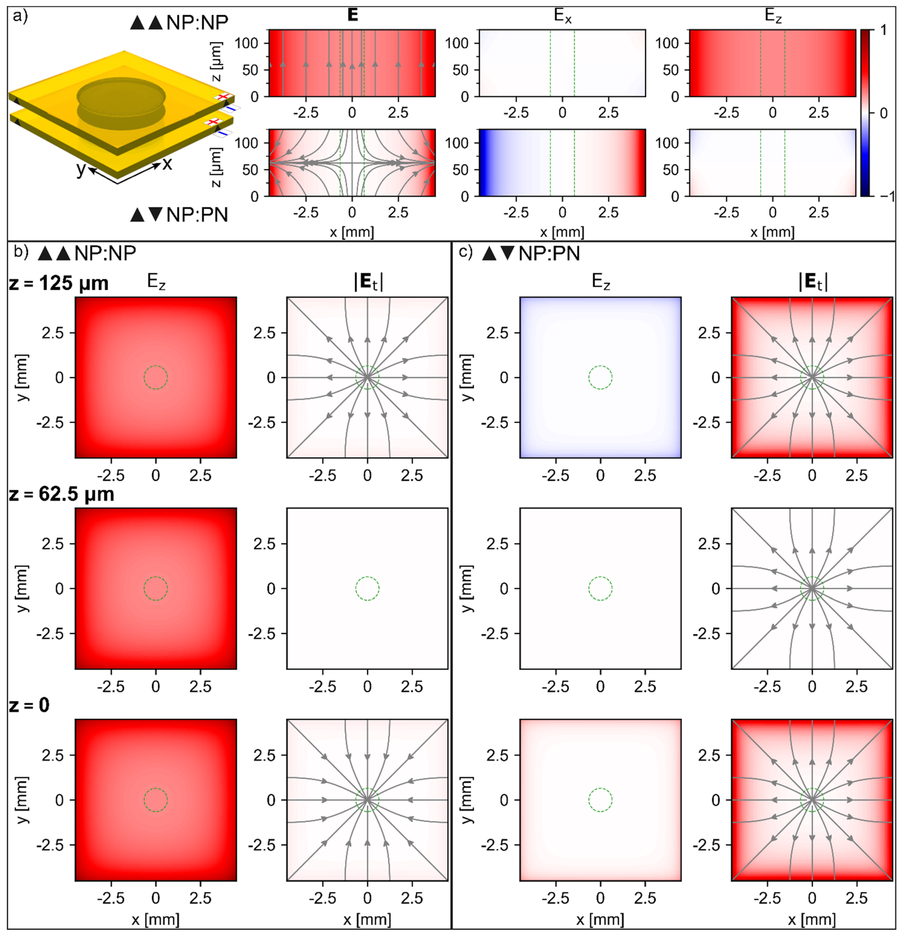
Figure 2.
a) Number of fluid jets ejected for each instability event for np/np (black squares) and np/pn (red circles) cells, as a function of the instability temperature; b) average radius of the NF fluid bridge measured from the cells top view, after each instability event for np/np (black squares) and np/pn (red circles) cells, as a function of the instability temperature. Full lines are just guides for the eyes. Data shown in figure are related to two specific cells. However, the same measurements have been repeated several times on different samples and gave reliable results.
Disclaimer/Publisher’s Note: The statements, opinions and data contained in all publications are solely those of the individual author(s) and contributor(s) and not of MDPI and/or the editor(s). MDPI and/or the editor(s) disclaim responsibility for any injury to people or property resulting from any ideas, methods, instructions or products referred to in the content. |
© 2024 by the authors. Licensee MDPI, Basel, Switzerland. This article is an open access article distributed under the terms and conditions of the Creative Commons Attribution (CC BY) license (http://creativecommons.org/licenses/by/4.0/).
Copyright: This open access article is published under a Creative Commons CC BY 4.0 license, which permit the free download, distribution, and reuse, provided that the author and preprint are cited in any reuse.


