
Submitted:
05 April 2024
Posted:
08 April 2024
You are already at the latest version
Abstract
Dealing with and maintaining high-quality standards in the design and construction phases is challenging, especially for on-site construction. Issues like improper implementation of building components and poor communication can widen the gap between design specifications and actual conditions. To prevent this, particularly for energy-efficient buildings, it's vital to develop resilient, sustainable strategies. These should optimize resource use, minimize environmental impact, and enhance livability, contributing to carbon neutrality by 2050 and climate change mitigation. Traditional post-occupancy evaluations, which identify defects after construction, are impractical for addressing energy performance gaps. A new, real-time inspection approach is necessary throughout the construction process. This paper suggests an innovative guideline for prefabricated buildings, emphasizing digital 'self-instruction' and 'self-inspection'. These procedures ensure activities impacting quality adhere to specific instructions, drawings, and 3D models, incorporating relevant acceptance criteria to verify completion. This methodology, promoting alignment with planned energy-efficient features, is supported by BIM-based software and Augmented Reality (AR) tools, embodying Industry 4.0 principles. BIM and AR bridge the gap between virtual design and actual construction, improving stakeholder communication and enabling real-time monitoring and adjustments. This integration fosters accuracy and efficiency, key for energy-efficient and Nearly Zero-Energy Buildings, marking a shift towards a more precise, collaborative, and environmentally sensible construction industry.
Keywords:
building inspection
; decarbonization
; digitalisation
; energy-efficient buildings
; environmental sustainability
; Nearly Zero-Energy Buildings
; prefabricated buildings
; quality assurance
1. Introduction
The European Union (EU) is acting upon the European Climate Law and the European Green Deal to make Europe’s economy and society climate-neutral by 2050 with an intermediate target of reducing net greenhouse gas emissions by at least 55% by 2030 compared to 1990 levels. Within this goal, the European Commission noted that buildings are the single largest energy consumer in Europe, using 40% of our energy, and creating 36% of our greenhouse gas emissions; and the construction sector is responsible for over 35% of the EU’s total waste generation. Therefore, there is an urgent need for deep renovation of the worst performing building stock along with a pathway for transforming the building stock into zero-emission buildings by 2050.
The impact of such an action can only be achieved when the building quality and energy performance requirements are fulfilled during the deep renovation and new construction projects, at the commissioning and delivery of the existing or new buildings, and especially during the lifecycle operation and maintenance of the buildings.
In consideration of what has been introduced, dealing, and ensuring high quality standard during the design and construction stages can often be challenging for all involved actors and players, particularly in the case of on-site construction where often the improper implementation of building components and ineffective communication among the professionals in design, production, and construction phases may lead to a widening gap between the design specifications and the as-built conditions.
To address these challenges, especially in new construction and renovation of Nearly Zero-Energy Buildings (NZEB), it is necessary to develop strategies to meet the quality and performance standards (e.g. energy, indoor environmental quality, etc.) and to ensure the buildings’ resilience against climate change [1].
These strategies should aim to optimize resource utilization, reduce environmental impact, and enhance the overall livability and sustainability of the built environment. This approach would contribute significantly to achieving carbon neutrality by 2050 and mitigating the cause of climate change.
To overcome the limitations of the widely known Post-Occupancy Evaluation (POE) approach particularly in terms of energy, wherein numerous defects and gaps become impractical to rectify when the building has been constructed, it is essential to introduce a new inspection methodology and monitoring -in real time- of the building performance. This new methodology should be conducted in real-time and systematically implemented at each stage of the building process.
Based on the results achieved from the EU Horizon 2020 research project titled INSITER (Intuitive Self-Inspection Techniques using Augmented Reality for construction, refurbishment and maintenance of energy-efficient buildings made of prefabricated components) [2] as well as the subsequent studies and practical experience gained by the research team, this paper introduces an innovative methodology which adopts digitalised procedures to reduce the gap between As-Built and As-Designed. This methodology is set to revolutionize the industry, offering a way to ensure that the constructed or renovated buildings align with the initially planned NZEB features.
In this methodology, cutting-edge BIM-based software tools, Augmented Reality (AR) applications and Digital Twins are pivotal for streamlining the procedures.
Embracing the principles of Industry 4.0, the proposed solutions harness the transformative potential of technology within the construction realm where BIM and AR technologies play a crucial role in bridging the virtual design environment (off-site) and the real production and construction environment (on-site).
Considering the high ambition, pressing timeline, and huge volume of the existing and new building stock to deal with, cost-effective and scalable innovation for lifecycle quality and performance assurance, monitoring and optimisation is highly demanded. Digitalisation is believed to be an important factor.
This paper presents applied research on this topic to improve the environmental impact of the construction sector with innovative inspection methodologies which adopt the advantages proposed by the Industry 4.0.
2. Research Goals and Methodology
Recent studies [3,4,5,6] highlight a disconcerting trend: buildings designed to be energy-efficient tend to consume 2 to 5 times more energy in the occupancy phase compared to the initially predicted energy consumption during their design phase.
This discrepancy is attributed to several factors, including construction errors, climate variations, substandard building materials, and suboptimal user behaviors. While these factors account for long-term energy performance differences, they do not fully explain the immediate surge in the post-construction or post-renovation energy consumption [7].
The energy performance of a building is closely linked to the quality of the executed construction or renovation. This also applies to buildings constructed using prefabricated components of which technical and energy performance has been calculated and tested before assembly. Evidently, defects and errors at on-site construction significantly reduce their high performance [8].
Construction errors are mainly caused by:
- Difficulty in understanding the technical specifications of the project and assembly manuals by on-site workers.
- Lack of practical and intuitive assembly instructions from the designers and/or manufacturers.
- Miss-communication flaw among the various stakeholders throughout the process, exacerbated by the diversity of their skills, capabilities, roles, and responsibilities.
- Assembly, installation, and inspection procedures based on the construction workers’ and operators’ experience and their skills to follow specific protocols.
The fourth industrial revolution introduced digital tools and information platforms that improved design precision and overcame some limitations [9,10].
To effectively achieve the objectives of NZEB, it is critical to address the aforementioned issues. Hence, innovative methods and procedures need to be proposed to eliminate errors during construction or renovation process to avoid the gaps in quality and energy performance between design and realization.
The research goal of this paper is to define a new building inspection approach for construction and refurbishment of NZEB building leverage the opportunities presented by the fourth industrial revolution, especially by extending the application of Building Information Modeling (BIM) to the construction occupancy and maintenance phase through Mixed Reality, which interlinks the Real Environment (RE), Augmented Reality (AR), Augmented Virtuality (AV), and Virtual Environment (VE).
The research methodology adopted has included eight steps:
- Conduct site mapping and assessment using self-inspection software for renovation or construction projects.
- Implement self-inspection in the selection and quality control of prefabricated components, integrating with BIM systems.
- Utilize BIM modeling for detailed planning of building components and installations, following IFC standards.
- Apply BIM-based AR for self-instruction and inspection, enhancing construction workers' understanding and efficiency.
- Validate building quality and performance virtually via BIM, addressing errors through self-inspection and collaboration for solutions.
- Carry out self-inspection and instruction during site preparation, optimizing logistics and updating construction plans.
- Perform ongoing self-evaluation during construction or renovation to ensure component accuracy and process efficiency.
- Finalize self-inspection and instruction in pre-commissioning to identify common construction errors and their impacts.
The innovative inspection methodology presented in the following sections adopted the assumption of prefabricated elements and systems are factory-made and "error-free", which means that they have already been tested in the laboratory so they should meet the performance requirements and conform to the quality standard.
3. Preliminary Analysis
Global energy consumption in buildings has increased annually by 1.1% since 2010, driven by rising demand in emerging economies, particularly China and India, with efficiency gains stabilizing or reducing consumption in the US, EU, and Japan [11].
As assessed by the IEA's Tracking Clean Energy Progress (TCEP) Report [12], one of the sectors that is critical for clean energy transitions and the goal of the Net Zero by 2050 is the building sector. The building sector constitutes more than a third of worldwide energy usage and emissions due to the energy utilized for construction, heating, cooling, and lighting of residential and commercial buildings along with the energy consumption of appliances and equipment.
- Regarding the goal for NZEB, the current progress is as follows:
- Progress of the lighting component is on track to meet the Net Zero by 2050 Scenario.
- Progress of the space cooling, heating, heat pumps, appliances and equipment components needs to go faster as the continuation of the current trends without any acceleration would result in an achievement that is far behind the trajectory of the Net Zero scenario by 2050.
- The progress of the building envelope component is not on track, which indicates that the recent trends are either moving in the opposite direction or marked inadequate by 2030 to align with the Net Zero by 2050 goal.
To propose an advancement on the state of the art of the energy efficiency of the building envelope, this section is dedicated to defining the most common installation errors, inspection procedures, Key Performance Indicators (KPIs), and the corresponding measurement aspects.
3.1. Building Envelope: Classification and Inspection Procedures
It is clear that the role of the building envelope –which can be defined as the collection of parts of a building that form the primary thermal barrier between the interior and exterior– is fundamental in determining the levels of comfort, natural lighting, and ventilation as well as the amount of energy required to heat or cool a building. Additionally, its design and construction greatly influences the comfort and productivity of the building occupants [13,14,15].
Although achieving energy neutrality is easier in new buildings, deep renovation and expansion of existing buildings can also attain a significant energy improvement, for instance the energy consumption can be reduced up to 30-50% by insulating the external walls and roofing systems of the building [16].
The first step in to reach the expected quality of the building envelope involves planning a systematic set of surveys, inspections, collection, and analysis of parameters related to specific energy consumption, linked to the operational conditions of the building and its systems as well as to the technical and economic assessment of energy flows. For methodological simplicity, the building envelope is divided into various subsystems, each with its own characteristics.
Following the construction phase, four elements of the building envelope with a substantial impact on energy use are identified and classified as follows:
- Lower horizontal closures: foundations and ground floors, including the ground attachment and junctions with the facade. Ground floor elements and foundations are considered a specific subsystem due to their constant contact with the ground and the corresponding risk of performance loss.
- Opaque vertical closures: perimeter walls, including window openings. The vertical elements primarily present problems of connection with the building's structural frame and between different modules.
- Transparent vertical closures: fixtures and glazed facades (continuous facades). These components have similar problems to opaque facades in terms of air tightness and overall performance (acoustically and thermally). They also present specific issues related to the presence of glass panes and seals.
- Upper closures: roofing. These elements can be flat or sloped. Flat roofs are vulnerable to water accumulation, while sloped roofs must manage runoff water. Roofs are crucial in terms of energy saving, especially regarding heat loss and water tightness (waterproofing). The analysis of the roofing elements' performance also includes their connections with the vertical facade elements.
To develop effective inspection procedures for building envelope components, it is necessary to consider two key aspects that influence the behavior of a building's skin:
- the consistency of technical dimensional tolerances, and
- the state of joints and connections, in particular the interface between different elements that primarily influence the actual performance of the installed building components.
Tolerances can vary depending on materials and products. Adherence to dimensional tolerances ensures mechanical strength, functionality, and compatibility of each element with the rest of the structure and other non-structural components. Certain standards or guidelines (e.g., UNI EN 13369: 2013 Common rules for precast concrete - Annex J) define geometric constraints, surface imperfections, measurement methods, and acceptable deviations of a prefabricated element's surface, but many products lack evidence of their compliance to an applicable standard. Therefore, defining the right procedures is particularly important on-site, where regular inspections are necessary to ensure the compliance with the specified requirements.
Regarding connections, various forms of linkage can be identified, particularly the connections between components that constitute the envelope itself (internal connections) and between the outer skin and the building's load-bearing structure or other parts of the building, such as the basement and roofing system (considered as external connections). The forms and methods of joining vary according to the materials and products used, the structural type of the building, and the number of functional layers comprising the envelope system.
All elements have geometric differences, but dimensional tolerances must fall within a certain limit. Not only the dimensional tolerances of the element are important, but also those of the openings where the element is placed. Joints where tolerances are not acceptable due to a greater geometric difference than allowed which cannot be resolved on-site, must be rejected and sent back to the factory. This requires the development of communication protocols with the manufacturing company and possibly the cancellation of the delivery of other components for which similar errors are anticipated. Certain joints known as 3D joints are the most critical parts where potential errors can occur with significant impact on the building's energy performance, especially when they behave as voids. This problem must be resolved on-site. At the same time, 2D connections are also important when analyzing critical components. In this regard, a "joint approach" has been developed to study the building components and reduce the complexity of the problem.
Prefabricated components can be made of wood, steel/aluminum, concrete, polymers, and a variety of composites created from the combination of the aforementioned materials. Being prefabricated systems, regardless of the materials used, the performance and quality of the system must comply with industry standards. For systems that satisfy the performance standard and have already been tested in the laboratory, the proposed methodology and tools are sufficiently generic and applicable independently from the materials that compose the systems.
Prefabricated elements delivered to the construction or renovation site are considered error-free. However, sample tests must be conducted on-site to assure the quality. Elements arriving at a construction site can be damaged during transport and must be inspected on-site to check for defects. The communication protocols related to this self-inspection are based on performance indicators, for which a four-phase approach is introduced:
- Prefab as designed. This involves internal quality control at the factory.
- Delivered as prefabricated. Phase Zero of self-inspection upon arrival at the site, before assembly. It involves only the identification of the element and a sample inspection.
- Mounted as delivered. Assuming that no storage on-site is planned but immediate assembly, this phase involves measurement in case of dimensional evaluation of the foundations as a preliminary action.
- Performing as pre-calculated. This phase focuses on the construction of the building and all measuring devices capable of identifying possible errors, assessing their significance, and deciding their admissibility.
3.2. Building Envelope Construction Defects
The analysis of potential construction defects and the related methodological approach are complex by the extreme diversity of building materials, weather, standards, and local building design and construction practices. However, the assessment of the most common anomalies in building envelope construction can be generally traced based on literature review and long-term practice. A summary of the construction errors:
- Off-site production not conforming to the project.
- On-site production not conforming to the project.
- Poor production of components.
- Assembly of damaged building components.
- Incorrect assembly of components.
- Incorrect placement of components or non-compliant installation.
- Misinterpretation or improper use of documentation (e.g., technical drawings).
- Failure to install or assemble components different from the executive project.
- Geometric discrepancies of building components.
- Installation of unsuitable material.
- Fixtures not correctly sealed on-site.
- Irregular site inspection by the project manager.

Table 1.
Critical and Recurring Anomalies.
| Most common anomalies | Main impacts (qualitative assessment) |
|---|---|
| Geometric discrepancies | Unexpected discrepancies, water/vapor infiltrations with related interstitial condensation |
| Lack of insulation | Low U-value, thermal bridges |
| Lack of air tightness | Thermal bridges, water/vapor infiltrations |
| Unexpected increase of heat through transparent surfaces | Sensitivity to solar radiation, surface condensation, glare |
Table 2.
Summary of building components and their impact on energy performance. Resolving these anomalies can have significant impacts on energy performance.
Table 2.
Summary of building components and their impact on energy performance. Resolving these anomalies can have significant impacts on energy performance.
| Component/Interface | Impact on Energy Performance |
|---|---|
| Walls – Roofing – Basement | High levels of insulation - optimized through Life Cycle Costs (LCC) evaluation - in walls, roofs, and floors reduce heat loss, especially in cold climates. Highly reflective surfaces are advantageous in hot climates, including roofs and walls that are white and/or painted with cool colors, reducing glare |
| Glass Facades | High-performance windows and facades with low thermal transmittance for the entire system (including frames and seals) and climate-appropriate Solar Heat Gain Coefficients (SHGC) are the most advantageous solution |
| Interface (Joints and Connections) | Minimizing thermal bridges with high thermal conductivity fastening and structural elements (while managing moisture problems within the components and integrated building materials) ensures limited air infiltration percentages. Adequately sealed structures must guarantee controlled ventilation with air exchange. |
3.3. Key Performance Indicators
To assure the expected building quality through consistent inspection procedures, Key Performance Indicators (KPIs) have been defined to measure the performance of the entire building, such as air tightness, acoustic insulation, building quality, and energy efficiency.
There are two sets of KPIs with a particular relevance for building envelope, i.e.:
- Energy Efficiency (EE)
- Indoor Environmental Quality (IEQ)
Energy Efficiency (EE) is the ratio between performance, services, goods, or energy, and the input of energy (Directive 2012/27/EU). For buildings, it means using energy efficiently to ensure healthy and comfortable buildings. Therefore, the KPIs related to energy efficiency focus on:
- Heat transmission of the building envelope;
- Efficiency of heat/cold generation;
- Efficiency of heat/cold distribution.
Indoor Environmental Quality (IEQ), essentially described as the condition inside the building, typically includes air quality, access to daylight, view, pleasant acoustic conditions, and occupant control over lighting and thermal comfort (Kubba, 2017). In the set of KPIs on IEQ, the following parameters are considered:
- Thermal comfort;
- Visual comfort;
- Acoustics;
- Air quality.
It should also be noted that two aspects are particularly relevant for the energy performance of all building components:
- Geometry – in this context understood as the flatness, settlement, sliding, shrinkage, or thermal movement– is the main property to consider and verify on-site.
- Air tightness –in this context understood as limiting air passage through the building envelope– is essential for ensuring energy efficiency in new constructions and deep renovations and must be verified by conducting standardized tests. Air tightness alone can reduce heating requirements by 20-30%. Hermetically sealed structures, provided they have adequate ventilation control, can ensure a healthy indoor microclimate. Energy audits, like the mandatory energy performance certificates in the European Union, should include regular and validated tests on air leaks (for example, at least every 10 years).
From the process analysis, two main phases have been identified in which the choice of building components is critical for energy performance and where it is necessary to measure the KPIs, namely construction/assembly processes and performance analysis/evaluation:
- Construction/assembly processes are considered as the most critical phase for allowing the targeted energy performance to be achieved. Any defect in this phase can lead to anomalies, if not pathologies, that would hinder the quality and/or durability of the building's performance. Several solutions can be envisioned, such as: prefabrication of standard units to facilitate on-site assembly, on-site assembly processes with more careful and thorough performance control, deployment of sensors to monitor intermediate performance stages, continuous improvement processes as part of a quality process, and worker training on the impacts of incorrect component installation on final energy performances.
- Performance evaluation for existing buildings allows the users/owners/investors to monitor and manage energy consumption and user behaviors, identify potential incorrect use of the building systems due to a lack of awareness or knowledge of the users, and potential disturbances and/or pathologies of the building. Moreover, a condition-based maintenance approach can add value for performance guarantee contracts. This phase is crucial not only for maintenance, but above all, for a multi-criteria approach in the renovation of existing buildings.
3.4. Inspection Tools and Indicators
As mentioned earlier, the performance of the building envelope to be inspected and monitored is multifaceted.
KPIs are usually verified based on the data of energy consumption or building performance in multiple operations at various energy consumption levels. Numerous techniques exist for detecting and assessing significant parameters, but first a reference threshold should be established, comparable parameters should be identified, and achievable goals should be set. For this reason, the proposed methodology sets up specific protocols to measure the factors that affect energy performance. These factors are grouped into three main categories:
- Geometric Discrepancy/Moisture
- Positioning/Sensitivity
- Thermography/Diagnostics
Accordingly, the protocols are grouped as follows:
- Protocols for thermal tests
- Protocols for acoustic testing
- Protocols for testing geometric discrepancy
- Protocols for moisture testing
- Protocols for the testing of the localization system.
The analytical methods for carrying out the measurements and application are outlined in the table below, highlighting the techniques and tools to be used.
Table 3.
Framework of measurement parameters, instruments, and detection elements.
| Parameters | Sensors or Measuring Instruments |
Objectives or Indicators |
|---|---|---|
| Thermal Contrast [K] | Thermal Camera | Structural Integrity |
| Dimensional Difference [m] | Geometric Discrepancy | Geometric Discrepancy |
| U-Value [W/m2K] | Thermal Camera, Thermal Flow Transducer | Thermal Transmittance |
| HD [W/K] | Thermal Camera | Thermal Bridge |
| Thermal Bridge [L] | 3D Laser Scanner 3D | Moisture |
4. Innovative Inspection Methodology Based on Self-Instruction and Self-Inspection Procedures
Taking into account the analyses conducted and the results obtained, especially investigating the building envelope, an innovative building inspection methodology has been developed. The methodology embraces a novel concept of self-instruction and self-inspection procedures throughout the entire building's lifecycle, addressing each of its constructive parts. This approach aims to guarantee the anticipated building quality and energy performance.
The recommended procedures can be employed by construction workers, component suppliers, subcontractors, and all actors involved in the building’s lifecycle. A set of hardware and software tools support these procedures during all phases of the building’s lifecycle, from conception to realization and occupancy. The procedure is also supported and valorized by Mixed Reality technologies to improve the construction workers’ or operators’ activities by enabling them to visualize virtual design models during the actual construction or renovation phase, and thus overcoming incorrect interpretations of the design information.
The methodology consists of eight steps:
- Step 1: Utilizing self-inspection software, building occupants, owners, technical advisors, and inspection specialists conduct a comprehensive mapping of the current technical state of the site and/or the existing building. This includes an as-is condition assessment and real estate valuing in case of renovation.
- Step 2: Self-inspection in the procurement, production, and delivery of prefabricated building components, which includes pre-qualification selection via quality management based on the criteria for contractors and suppliers that have competencies in industrialized design, engineering, and energy-performance labeling. This step encompasses integrating manufacturers' 3D product databases with BIM systems and performing in-factory/pre-delivery product inspections.
- Step 3: BIM modelling of the building (new or existing), including detailed modelling of the building components and MEP/HVAC installations that are critical for the building quality and energy performance. BIM is created according to the open and interoperable international standard IFC (Industry Foundation Classes).
- Step 4: Generating and deploying BIM-based AR for self-instruction and self-inspection by embedding BIM and VR in AR and translating BIM/VR process information into self-instructions for construction workers. The Mixed Reality model will be made available on mobile devices of the construction workers. Data from the hardware tools for inspections will be interfaced with BIM and the inspection software.
- Step 5: Virtual validation of quality and performance through BIM model checking and clash detection as well as process optimization by means of VR simulation. When errors are found, self-inspection protocols will be applied for reviewing the clash details, determining the severity of the clash, tracing back of the defaulting components to their manufacturers/suppliers and asking these actors to perform a review and propose a recovery solution, and finally, damage prevention or collaborative recovery involving multiple actors.
- Step 6: Self-inspection and self-instruction during preparation of the construction site and logistics. This step includes checking the construction site and update of site’s BIM model based on the actual conditions, optimizing the time and cost schedules by analyzing the risks of delay and budget-overrun, and updating the self-instruction guidelines for construction workers.
- Step 7: Performing self-inspection and self-instruction during construction, renovation or maintenance process. This step includes checking the correctness and conditions of the delivered prefab components, implementing self-instructions on construction worker mobile devices, comprehensively evaluating the process at certain intervals, performed by the site supervisor, and involving workers from the contractors and sub-contractors. The preliminary quality and performance results are quantitatively measured and analyzed as input for participatory decision-making with the building occupants.
- Step 8: Self-inspection and self-instruction during pre-commissioning, commissioning, and project delivery. A preliminary and crucial step for the elaboration of the proposed methodology is the analysis of the most common construction errors and the identification of the building components that are most affected by these errors in consideration to the fact that both the defect and the type of element will significantly affect the building's quality and energy performance, as well as its construction costs and timelines.
The proposed methodology is versatile and applicable to various scenarios, including new construction, maintenance, and renovation projects.
5. Case Study
To exemplify the application of the proposed inspection methodology in a real construction project, this paper discusses the deep retrofit, redesign, and transformation of an abandoned university building, part of the campus of the University of Twente, in Enschede, East of the Netherlands. The existing building, erected in 1965, has been renovated and transformed into a student housing (75%) and a hotel (25%).
Figure 1.
State of the building before (March 2009) and after (August 2022) deep renovation.
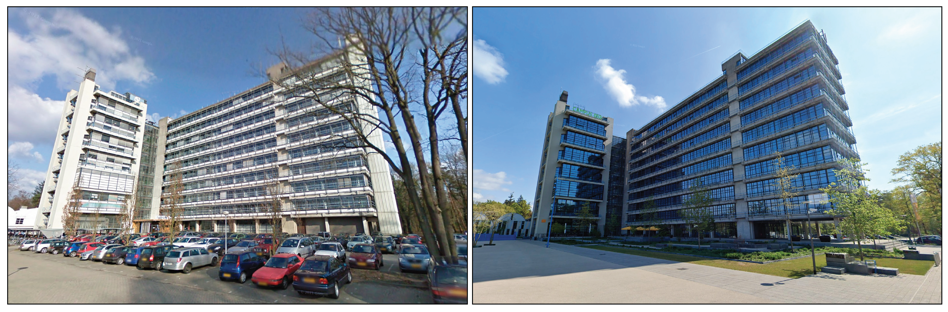
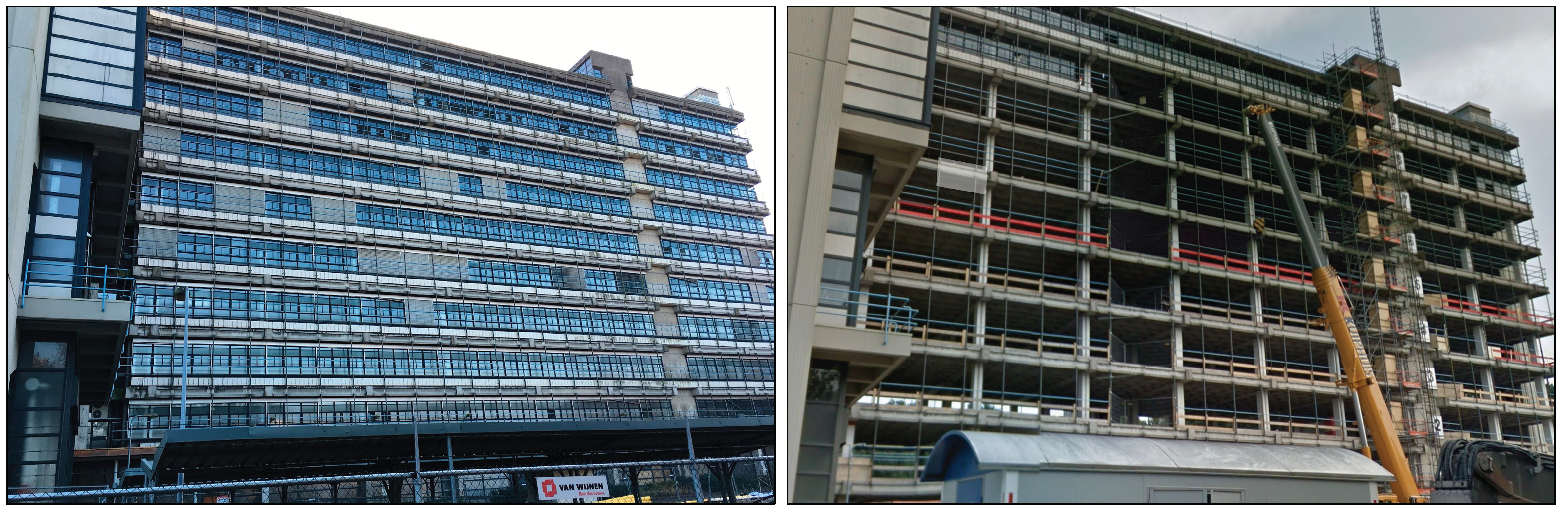
Figure 2.
State of the building during the deep renovation reveals the dismantling of the existing elements of the facade, alongside the preservation of the reinforced concrete structure.
Figure 2.
State of the building during the deep renovation reveals the dismantling of the existing elements of the facade, alongside the preservation of the reinforced concrete structure.
This demonstration case holds significant replication potential, driven by the imperative to enhance the energy efficiency of a substantial existing building stock in Europe. Additionally, the relevance extends to the current scenario where numerous university campus buildings dating back to the 1960s are being replaced by more contemporary structures. European universities face challenges in identifying transformation opportunities for these aging buildings, seeking solutions that not only prioritize energy efficiency but also contribute new functional value to the institutions.
The condition prior to intervention was subpar: utility systems (MEP) had reached the end of their lifespan, and the building façade was outdated in terms of energy efficiency. Only the concrete basement, rib floor plates, and the main structural concrete construction were deemed suitable for reuse.
The design decisions for the building retrofit were exclusively oriented towards the adoption of prefabricated plug-and-play solutions. The following prefab retrofitting solutions has been implemented in the building:
- Installation of new building envelope;
- Modular units of kitchens and bathrooms;
- New MEP / HVAC systems.
The construction, including demolition and remediation, has started in April 2017 and completed at the end of 2018.
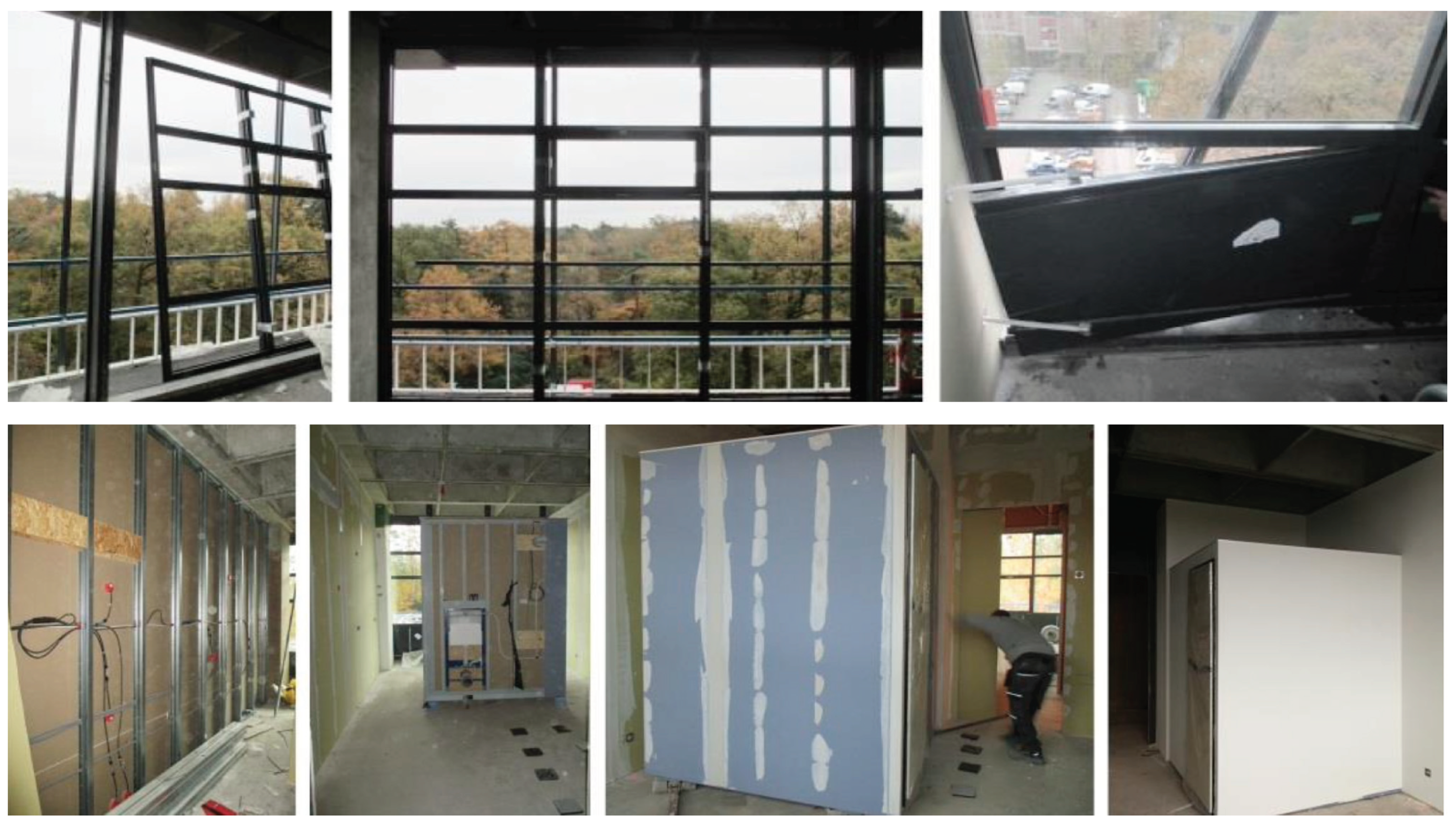
Figure 3.
Renovation of a student apartment: placing of new prefab building facade and bathroom unit.
Figure 3.
Renovation of a student apartment: placing of new prefab building facade and bathroom unit.
Based on the 8 steps of the introduced inspection methodologies, the field demonstration activities focused on:
- Inspection of deviations or flaws at the placement of new façade panels and windows (building facade). The installed façade panels and windows in real live has been compared to the BIM model and inaccuracies and defects has been identified using geometrical survey using 3D laser scanning and thermal scanning and acoustic measurement at critical joints in the façade system.
- AR on-site simulation at the assembly / installation of a part of the new MEP-HVAC system. The aim of the demonstration was to propose efficient design and installation process with minimalizing potential errors by using the INSITER tools.
5.1. Inspection Demonstration on Building Façade
The purpose of the first demonstration was to verify the connection between the prefab façade elements and the original construction of the building to avoid energy loss. The information was important for the contractor and the workers on site (mounting crew of the façade elements): firstly, to identify potential thermal bridges, to repair the deficiencies but also to take action in order to prevent those deficiencies in the future.
The inspection demonstration activities on the building envelope have been performed following these steps:
- Step 1: Pre-renovation condition assessment and checking structural adequacy of substructure for installation of new panels and windows on the existing building.
- Step 2: After self-inspection of building components in the procurement and production the prefabricated panels has been delivery to the building site and storing them on-site for new inspection by scanning RFID or QR, and retrieval of component’s ID in BIM. During the transportation task the key persons involved was the construction workers/installers and production/manufacturing workers. They were responsible of the correct delivery on site of the component and the correct storage of the components.
- Step 3: BIM modelling, including detailed modelling of the building components and MEP/HVAC installations that are critical for the building quality and energy performance. Deployment of BIM models for on-site use. Loading the partial BIM model onto a tablet (iPad), showing the specific parts of the façade including the panels.
- Step 4: Creation and implementation of a BIM-based Augmented Reality (AR) system for self-instruction and self-inspection in construction. All information will be for construction workers and accessible on workers' mobile devices to reduce potential construction errors.
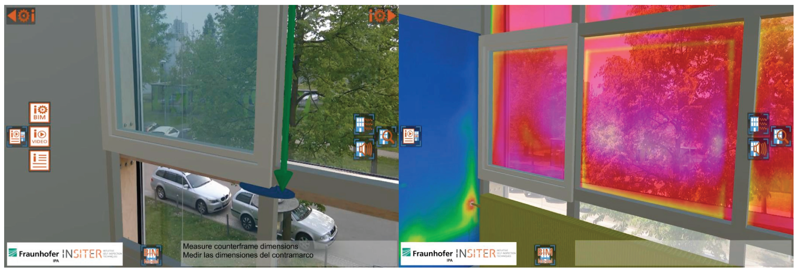
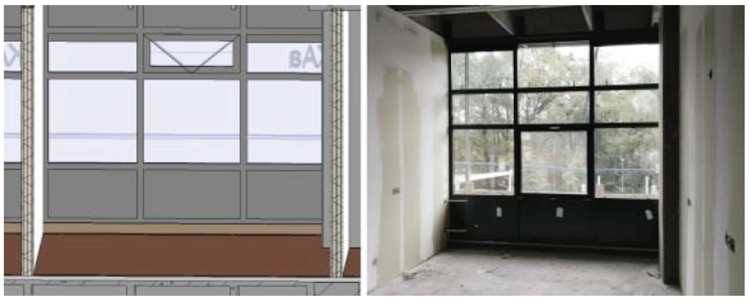
Figure 4.
INSITER BIM-based Self-Instruction AR app visualizing thermal measurements images to evaluate thermal deviations and there causes with the help of the digital BIM model and the on-site situation.
Figure 4.
INSITER BIM-based Self-Instruction AR app visualizing thermal measurements images to evaluate thermal deviations and there causes with the help of the digital BIM model and the on-site situation.
- Step 5: Virtual validation through BIM model checking and clash detection was performed.
- Step 6: The prefabricated components, produced off-site, were assembled on-site using self-instruction procedures accessible through mobile devices. A continuous on-site visual comparison with the Building Information Modeling (BIM) model was performed to ensure the quality of the work aligned with the project plan and met the anticipated requirements consistently.
Figure 5.
Comparisons between real live situation and the BIM model.
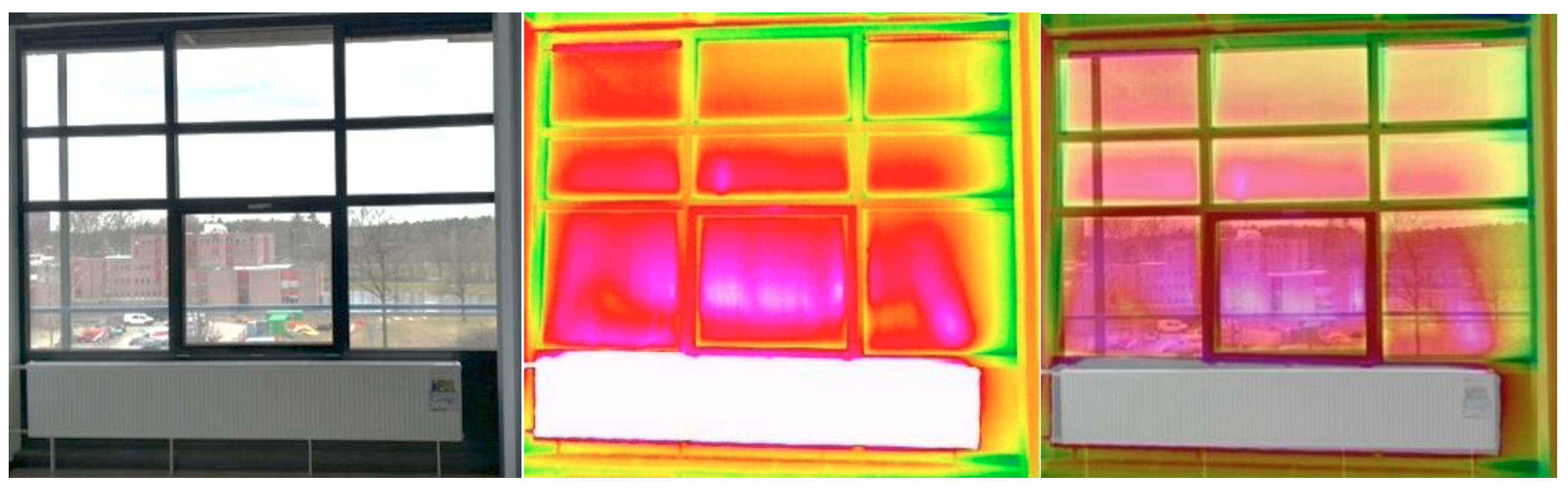
- Step 7: After completion of the installation of the new panels, self-inspection of the building facade through thermal and laser scanning was carried out. Checking if the measured values (i.e. the sizes of the gaps) were acceptable (within the tolerance), to avoid thermal bridges, airtightness and leakages and performing thermal scanning to identify thermal bridges. With a thermographic camera an infrared scanning was performed for a quality control resulting in thermal imaging indicating whether there were thermal / energy losses in the new façade. The INSITER procedure for the quantification of the effect of thermal bridges in terms of building envelope thermal transmittance was based on infrared camera measurements. This method was applied to a room of the University of Twente building. The room has one external wall and three internal walls. Scope of the inspection was to verify that a thermal gradient of about 10°C between inside and outside exists. Usually, a good insulated facade guarantees this thermal gradient, otherwise the room must be conditioned to detect thermal bridges.
Figure 6.
Inspection by thermal scanning image during the construction work. From the left: real picture of window closed; undistorted IR image-Window closed; overlapping window closed.
Figure 6.
Inspection by thermal scanning image during the construction work. From the left: real picture of window closed; undistorted IR image-Window closed; overlapping window closed.
5.2. Inspection Demonstration on MEP-HVAC
MEP-HVAC systems installed in existing buildings pose challenges for retrofitting due to the dispersed nature of their components throughout different spaces, including indoor and outdoor elements in various floors and ceilings. However, when opting for deep retrofits of buildings, strategic decisions regarding MEP-HVAC systems can substantially contribute to overall energy savings. The objective of the demonstration was to introduce an efficient design and installation process, leveraging INSITER tools. In this case study, the focus was on ensuring the accuracy of BIM-modeled MEP components and retrofit elements, with the aim of minimizing potential errors during the retrofitting process.
The inspection demonstration activities on new MEP system have been performed following these steps of the proposed methodology:
- Step 1: Pre-renovation condition assessment specifying building characteristics and checking the technical condition including building type, orientation, area, envelope, usage etc., as well as national building regulations, mandatory technical requirements for HVAC systems and requirements for indoor environmental quality (IEQ).
- Step 2: Checking the particular MEP components delivered on the building site. Scanning RFID or QR of the MEP components and retrieval of component’s ID in BIM. This stage requires retrieving a list of materials form the BIM and collecting the (prefabricated) components that have to be installed.
- Step 3: BIM modelling of the existing building, including detailed modelling of the building components and MEP/HVAC installations that are critical for the Indoor Environmental Quality and energy performance. Deployment of BIM models for on-site use. Loading the partial BIM model onto a tablet (iPad), showing the specific parts of MEP-HVAC.
- Step 4: Creating and implementing BIM-based Augmented Reality (AR) for self-instruction and self-inspection involves integrating BIM and VR into AR, translating BIM/VR processes into self-instructions for construction workers. The Mixed Reality model will be accessible on the mobile devices of construction workers, and data from hardware tools will interface with BIM and inspection software for effective inspections.
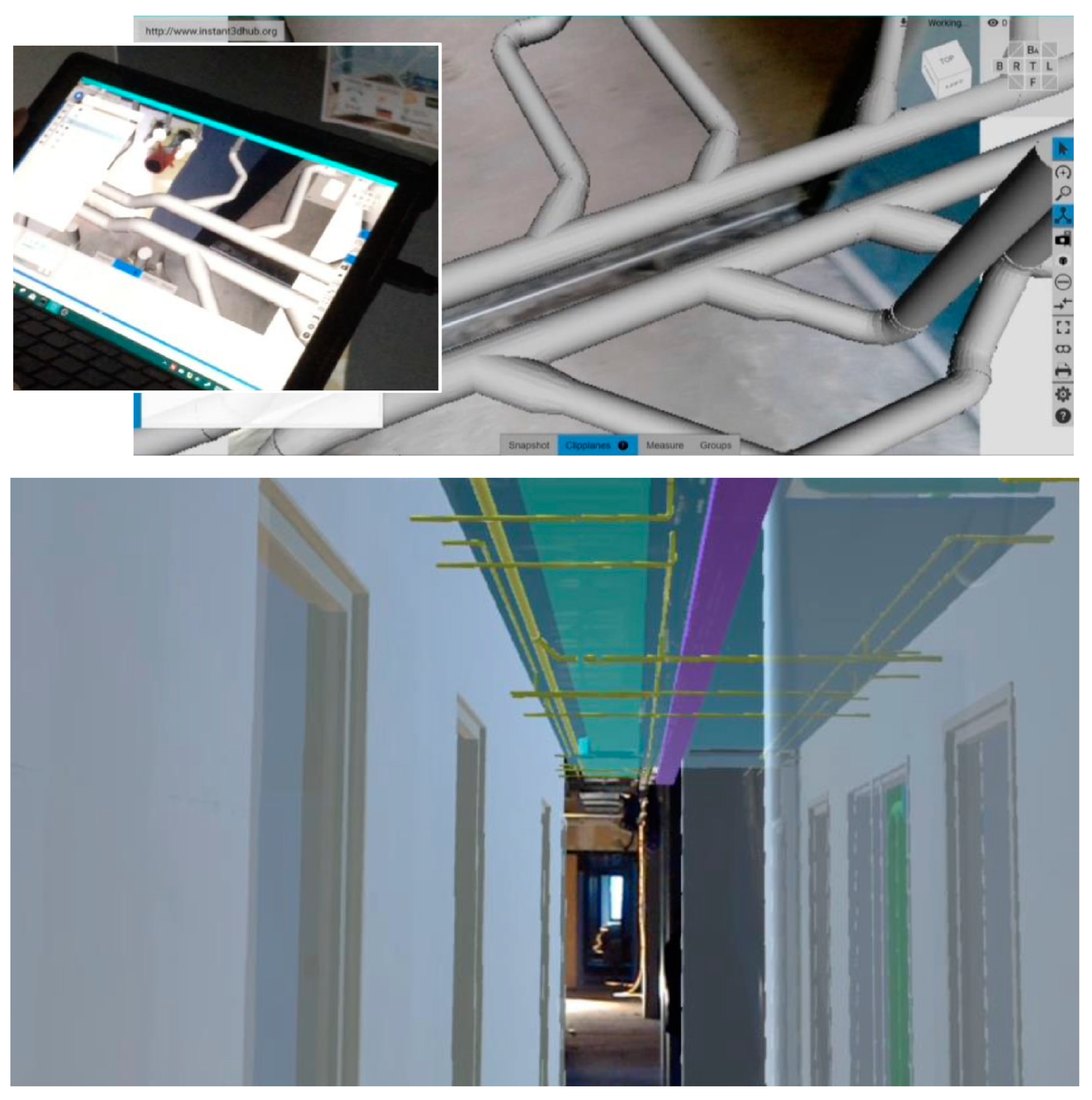
Figure 7.
BIM AR and MR Vision App. MEP and HVAC systems self-instruction for construction workers.
- Step 5: The clash detection process involves defining parameters, preparing the BIM model, and conducting clash detection by scrutinizing all MEP trades. Employing the 3D clash detection method aims to expedite the design coordination process and ensure a thoroughly coordinated design.
- Step 6: Using Augmented Reality to check possible installation of the designed MEP components. In detail, checking the design scenarios, problematic situations, necessary interventions to the structure and use of materials. Preparing the building structure for the installation of the MEP components (e.g. checking the design scenario with the BIM model for drilling holes if necessary).
- Step 7: Installation / replacement of the MEP systems in the building. Using BIM model to check accuracy. The installation has been followed by placement of the sanitary and kitchen modules according to a manual from the manufacturer. The installation procedure has been checked with the BIM model for any discrepancies. After the installation started the self-inspection activities troughs deployment of Augmented Reality tool at the location where the MEP components are installed adopting this procedure: loading the BIM on a portable device (tablet); setting the positioning and orientation points for AR; visual inspection of the installation work using AR; project AR overlay over the installed components/ducting to verify correct installation, course and location.
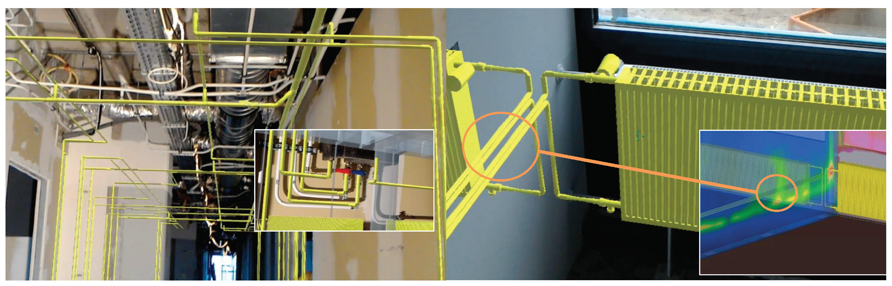
Figure 8.
INSITER HoloLens BIM-based Mixed Reality App Screenshots for self-inspection. On-Site Demonstration focus on heating system with visualization of instrumentation measurement data concerning thermal deviations and heat dispersion of heating pipe.
Figure 8.
INSITER HoloLens BIM-based Mixed Reality App Screenshots for self-inspection. On-Site Demonstration focus on heating system with visualization of instrumentation measurement data concerning thermal deviations and heat dispersion of heating pipe.
6. Results and Discussion
The adoption of innovative inspection methodologies, coupled with the installation of new prefab solutions for the building's envelope and HVAC systems (Heating, Ventilation, and Air Conditioning), along with the utilization of embodied energy, resulted in energy savings of up to 70% compared to the pre-renovation state. Additionally, the use of prefab solutions, encompassing façade panels and modular units for kitchens and sanitary facilities, facilitated a 50% reduction in the renovation timeline.
This success is also demonstrated by the final energy label post-deep renovation is now an A, a significant improvement from the G label the building had prior to the renovation.
7. Conclusion and Perspectives
In the dynamic panorama of global industrial evolution, the construction sector emerges as a fundamental battleground in the fight against climate change.
Industry 4.0 has inaugurated an era of transformation unprecedented, where digitalization is not just an addition but a central pillar in the search for sustainability. In a world where precision and efficiency are of a paramount importance, digitalisation and innovative inspection procedures become crucial for unlocking the full potential of NZEB.
Indeed, in the last ten years, the digitalization of the construction sector has produced a further acceleration in the reliability of procedures and tools that allow for the reduction of errors, the optimization of timing, and the reduction of costs.
Within the framework of the ongoing digital transition process, the inspection methodologies presented in this paper can contribute to further development of procedures and tools for quality management and, in particular, for the performance of energy efficiency over the building life cycle to reduce the environmental impact towards climate neutrality. Such potential could be increase on the integration of Information and Communication Technologies (ICTs) and Artificial Intelligence (AI) in the planning and management procedures as well as in design and maintenance activities on the existing building stock.
As demonstrated, the integration of digitalised process as well as digital tools-technologies does not only enhance the communication among stakeholders, but also serves as a dynamic tool for real-time monitoring and optimization throughout the building’s lifecycle. This ensures that the result of a new construction or a renovation aligns with the initially envisioned energy-neutral design.
In a particular historical moment of the sector where the interest in the valorization and deep renovation of the existing building stock is fundamental to attend the aims of the New European Green Deal and Renovation wave program toward decarbonization of the construction segment the building inspection became obvious important.
Periodic inspections have long been recognized as one of the main methods for evaluating the component's and building performance but also material's conservation, in particularly for building maintenance.
In fact, on the existing building stock, the results of inspections and the data from monitoring systems are an essential tool for choosing the best interventions to be carried out evaluating the deadlines for their execution, defining the specifications on products and technologies to be used, indicating the specializations and skills required of the operators who will have to execute them.
During the last year has been extensively demonstrated the computational power of AI is revolutionizing traditional practices, making them more efficient and intelligent.
Into the construction domain, the recent merger of AI technologies, mainly machine learning and deep learning systems, has catalyzed a paradigm shift. This integration opens the way to new procedures in planning, managing new constructions and restorations, as well as simplifying maintenance operations.
Summary, the ongoing advances driven by digitalization and its allied technologies introduced in this paper offer a range of sophisticated solutions to reduce the construction errors by self-instruction solutions and to evaluate building performance and conditions by self-inspection.
These advancements are indispensable for the inspection and assessment of buildings, with the final goal of preserving their efficiency and performance. Ensuring compliance with energy efficiency standards over time is not only a matter of regulatory compliance but is also crucial for minimizing the environmental footprint of buildings, thereby contributing significantly to the mitigation of the impacts of climate change.
Self-instruction and self-inspection procedures, combined with advanced digitalization technologies (BIM, Digital Twins, AR, etc.) create a synergy that will propel the construction industry into a new era of precision, collaboration and environmental awareness as the foundation for a climate-neutral future.
Author Contributions
Conceptualization, E. Piaia and B. Turillazzi.; methodology, E. Piaia; formal analysis, B. Turillazzi.; investigation, E. Piaia and B. Turillazzi, R. Sebastian.; resources, R. Sebastian.; data curation, R. Di Giulio.; writing—original draft preparation, E. Piaia, B. Turillazzi.; writing—review and editing, E. Piaia, B. Turillazzi, R. Sebastian; supervision, R. Di Giulio. All authors have read and agreed to the published version of the manuscript.
Funding
The INSITER project has received funding from the European Union’s Horizon 2020 Research and Innovation Programme under Grant Agreement No. 636063.
Conflicts of Interest
The authors declare no conflict of interest.
References
- https://ec.europa.eu/commission/presscorner/detail/en/IP_21_6683 (Accessed on 6th of March 2024).
- https://www.insiter-project.eu/en (Accessed on 2nd of February 2024).
- Ioannou, A. Itard, L.C.M., Energy performance and comfort in residential buildings: Sensitivity for building parameters and occupancy, Energy and Buildings, Volume 92, 2015, pp. 216–233, ISSN 0378-7788. [CrossRef]
- Martinaitis, V. Edmundas, E.K., Motuzienė, V., Vilutienė, T., Importance of occupancy information when simulating energy de-mand of energy efficient house: A case study, Energy and Buildings, Volume 101, 2015, pp. 64–75, ISSN 0378-7788. [CrossRef]
- Carpino, C. , Loukou, E., Heiselberg, P., Arcuri, N., Energy performance gap of a nearly Zero Energy Building (nZEB) in Denmark: the influence of occupancy modelling, Building Research & Information, 2020, 48:8, pp. 899–921. [CrossRef]
- Eon, C., Breadsell, J.K., Byrne, J., Morrison, G.M., The Discrepancy between As-Built and As-Designed in Energy Efficient Build-ings: A Rapid Review. Sustainability 2020, 12, 6372. [CrossRef]
- Mahdavi, A. Berger, C., Amin, H., Ampatzi, E., Andersen, R.K., Azar, E., Barthelmes, V.M., Favero, M., Hahn, J., Khovalyg, D., et al. The Role of Occupants in Buildings’ Energy Performance Gap: Myth or Reality? Sustainability 2021, 13, 3146. [Google Scholar] [CrossRef]
- Alencastro, J. , Fuertes, A., de Wilde, P., The relationship between quality defects and the thermal performance of buildings, Re-newable and Sustainable Energy Reviews, Volume 81, Part 1, 2018, pp. 883–894, ISSN 1364-0321. [CrossRef]
- Wang, M., Wang, C.C., Sepasgozar, S., Zlatanova, S., A Systematic Review of Digital Technology Adoption in Off-Site Construc-tion: Current Status and Future Direction towards Industry 4.0. Buildings 2020, 10, 204. [CrossRef]
- You, Z. , Feng, L., "Integration of Industry 4.0 Related Technologies in Construction Industry: A Framework of Cyber-Physical System. IEEE Access 2020, 8, 122908–122922. [Google Scholar] [CrossRef]
- IEA (2023), Energy Efficiency 2023, IEA, Paris https://www.iea.org/reports/energy-efficiency-2023, License: CC BY 4.0.
- IEA (2023), Tracking Clean Energy Progress 2023, IEA, Paris https://www.iea.org/reports/tracking-clean-energy-progress-2023, License: CC BY 4.0.
- Gan, V.J.L., Lo, I.M.C., Ma, J., Tse, K.T., Cheng, J.C.P., Chan, C.M., Simulation optimisation towards energy efficient green build-ings: current status and future trends. J. Clean. Prod., 2020, 254, 120012. [CrossRef]
- Lotfabadi, P. , Hançer, P., A comparative study of traditional and contemporary building envelope construction techniques in terms of thermal comfort and energy efficiency in hot and humid climates, Sustainability, 11, 2019, p. 3582. [Google Scholar] [CrossRef]
- Far, C. , Far, H. , Improving energy efficiency of existing residential buildings using effective thermal retrofit of building envelope, Indoor Built Environ. 2019, 28, 744–760. [Google Scholar] [CrossRef]
- Boriani, A. , Cariani, W., Romani, R., Agenzia Nazionale Efficienza Energetica - ENEA, Febbraio 2020, Guida pratica alla ristruttu-razione e riqualificazione energetica degli edifici per Amministratori di Condominio. I BONUS nel settore edilizio con le novità della Legge di Bilancio 2020 (Legge 27 dicembre 2019, n. 160, G.U. n. 304 del 30 dicembre 2019), p. 14., https://www.pubblicazioni.enea.it/download.html?task=download.send&id=18:guida-pratica-allaristrutturazione-e-riqualificazione-energetica-degli-edifici-per-amministratori-di-condominio&catid=3.
Disclaimer/Publisher’s Note: The statements, opinions and data contained in all publications are solely those of the individual author(s) and contributor(s) and not of MDPI and/or the editor(s). MDPI and/or the editor(s) disclaim responsibility for any injury to people or property resulting from any ideas, methods, instructions or products referred to in the content. |
© 2024 by the authors. Licensee MDPI, Basel, Switzerland. This article is an open access article distributed under the terms and conditions of the Creative Commons Attribution (CC BY) license (https://creativecommons.org/licenses/by/4.0/).
Copyright: This open access article is published under a Creative Commons CC BY 4.0 license, which permit the free download, distribution, and reuse, provided that the author and preprint are cited in any reuse.


