
Submitted:
07 June 2025
Posted:
11 June 2025
You are already at the latest version
Abstract
This article proposes a reconfiguration of the Michelson interferometer which introduces additional arrays of beam splitters, mirrors and detectors. It is expected to yield multiple interference patterns detectable by multiple detectors, enabling comparative analysis of the interference patterns. The number of interference patterns that can be generated is not limited but depends on the intensity of the beams and the number of available beam splitters required for certain experimental and Instrumentation purpose. The interference of multiple beams may improve sensitivity and detection for instrumentation purposes.
Keywords:
Interferometry
; instrumentation
; Quantum computation
1. Introduction
The Michelson interferometer was developed by Albert-A-Michelson as the central apparatus of the famed Michelson-Morley experiment [1,2] which was performed in 1887, meant to test the aether hypothesis but turned out to disprove the existence of aether and its dynamic properties.
Aether was initially believed to be the medium through which light travels, it was also believed that what is observed as vacuum had to be filled with this Aether medium allowing for the propagation of light waves. It was theorized that if the earth’s motion or light itself travels through the aether medium, and this medium also flows in a given direction, then the relative motion of the earth or light in same direction with the aether flow would be different from the motion of the earth or light in a direction opposite or perpendicular to the direction of aether flow. Hence if there is to be an interference of light from perpendicular directions, a small difference in path length or difference in velocity will be expected. This is because one of the light would arrive later than the other, as the aether flow will exercise drag on the light that is in a different direction relative to the flow.
To test for the properties of this hypothetical aether there was a need for a device that could measure the speed of light in the relative directions with great level of accuracy, and also detect small phase differences. Considering these needs, Michelson developed an interferometer that could do serve these purposes. A collaboration between Albert Michelson and Edward Morley was later made on an experiment to detect the differences in velocity between two light waves of different directions in the aether medium now known as the Michelson-Morley experiment [1,2].
However the results coming from the experiment performed using Michelson’s interferometer showed no difference in velocities, or any change in path length, annulling the hypothesis of an aethereal medium for the propagation of light. But this result aligned well with the theory of relativity that was later developed by Albert-Einstein, stating that the speed of light remains the same at all frames, positions and directions from which it is being observed.
The Michelson interferometer uses two beams both derived from a single beam splitted to two new sets of beams in perpendicular directions through the use of beam splitters, which are then interfered with a detector set to read the interference patterns. However the Michelson-Morley interferometer detects only a single interference pattern.
Apart from the Michelson-Morley experiment, the Michelson interferometer has found applications in the field of instrumentation, especially for practicals and experiments requiring the detection of small changes and micro-scale effects [3,4] . It is also applied in astronomical observations such as in LIGO (laser interferometer gravitational wave observatory) [5,6,7].
As stated previously, the Michelson interferometer is known to detect a single interference pattern/ fringes. But advances in interferometry led to the development of an interferometer that allowed the detection of two interference patterns, which is now known as the Mach Zehnder interferometer [8,9].
In search for an interferometer device with multiple detectable interference patterns, a potential interferometer design based on a modified Michelson interferometer is being presented, one that would multiply the beams and interference patterns, by splitting an already split beam into more amount of beams and reflecting them back using mirrors such that the beams will interfere perpendicularly before reaching their respective detectors.
The proposed reconfiguration would enable the generation and detection of n-number of interference patterns arising from the crossed paths of multiple beams. Where the multiple beams originate from a single light source/ laser beam that is first split into two and then to higher numbers.
Splitting of beams are achieved through the use of beam splitters that partially reflects light coming from a source. The number of split beams that can be used in this interferometer is not fixed and is only dependent on the specific requirement of the experiment or its practical applications.
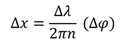
2. How the Michelson Interferometr Works
Michelson interferometry basically starts with a light source, preferably a laser which emits light in the form of a beam that is directed towards a single beam splitter. This partially reflects the beam in one direction and at the same time allows some of the beam to pass through it. The partially reflected beam and the one that passes through the splitter will be perpendicular to each other, as they are both directed towards respective mirrors. The beams reflected by both mirrors will cross paths perpendicularly (this is how interference occurs). And finally one of the interfered beams will head towards a photo-detector that detects the fringes produced from interference and provides details of the phase changes and changes in optical path length.
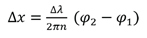
Mathematically we may define the difference in optical path length as;
Where ∆x defines the difference in optical path length and Δφ is the phase difference.
What we have below is a diagram showing how a Michelson interferometer is being set up and how the beams are being splitted, reflected, interfered and detected.
Figure 1.
The Michelson interferometer is very versatile and its applications spans across various fields and disciplines as an instrumentation device for detecting very small scale quantities and measurable with high level of precision. For example; the field of medicine optical coherence tomography (OCT) [13] is based on a device that is actually based on Michelson interferometry, large scale applications of Michelson interferometry in astronomy via. Gravitational wave detector (LIGO) also shows more of its versatility. Many other disciplines including Engineering have utilized setups and devices based on the Michelson interferometer for instrumentations involving microscale physical quantities and changes where great precision is needed.
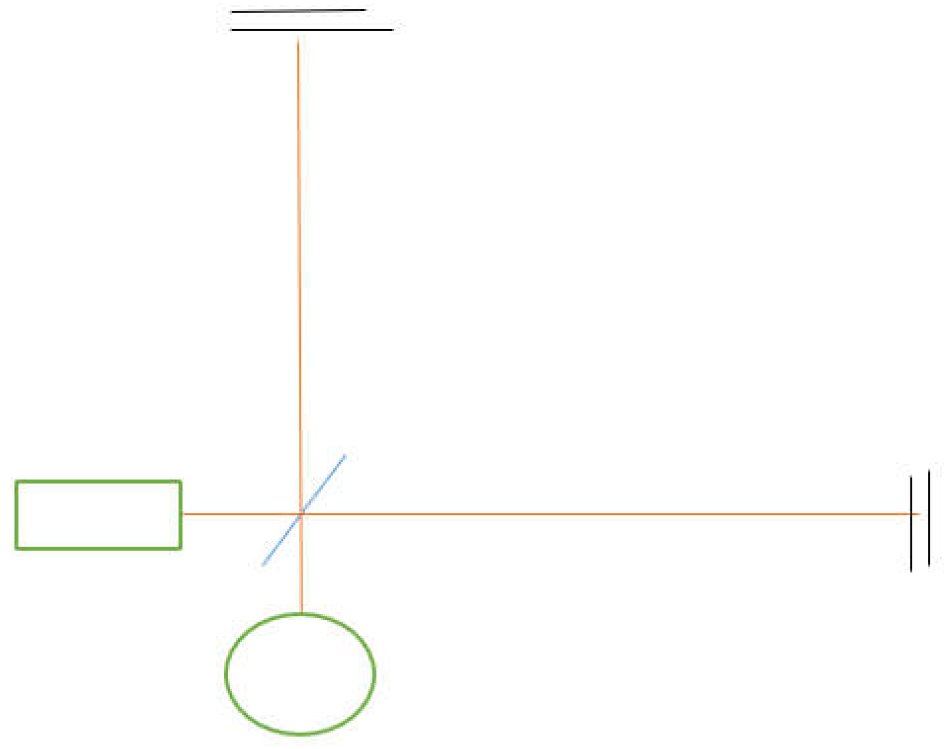
3. The Mach Zehnder Interferometer
The Mach Zehnder interferometer named after Ludwig Mach and Ludwig Zehnder, was first proposed in an article by Zehnder in 1892 and the proposed interferometer was further refined in another article by Mach in 1892.
This interferometer had unique differences in its design compared to the Michelson interferometer, in that it employs a closed geometry in its configuration of beam paths. Unlike the Michelson interferometer having open perpendicular paths. It also ensured that the beams cross paths in such a way that two interference patterns/fringes can be generated and detected separately making it one of the first multipath interferometer.
The Mach Zehnder interferometer is one of the most popular interferometers, and like the Michelson interferometer is also very versatile as an instrumentation device. Laboratories and institutions often apply interferometry to research and studies, with the Mach Zehnder interferometer as a preferred choice for instrumentation.
Figure 2.
4. Multipath Reconfiguration of the Michelson Interferometer
Although the Mach Zehnder interferometer generates already generates and detect two distinct interference patterns, but we can develop a reconfiguration of the Michelson interferometer enabling detection of more than just one or two interference output.
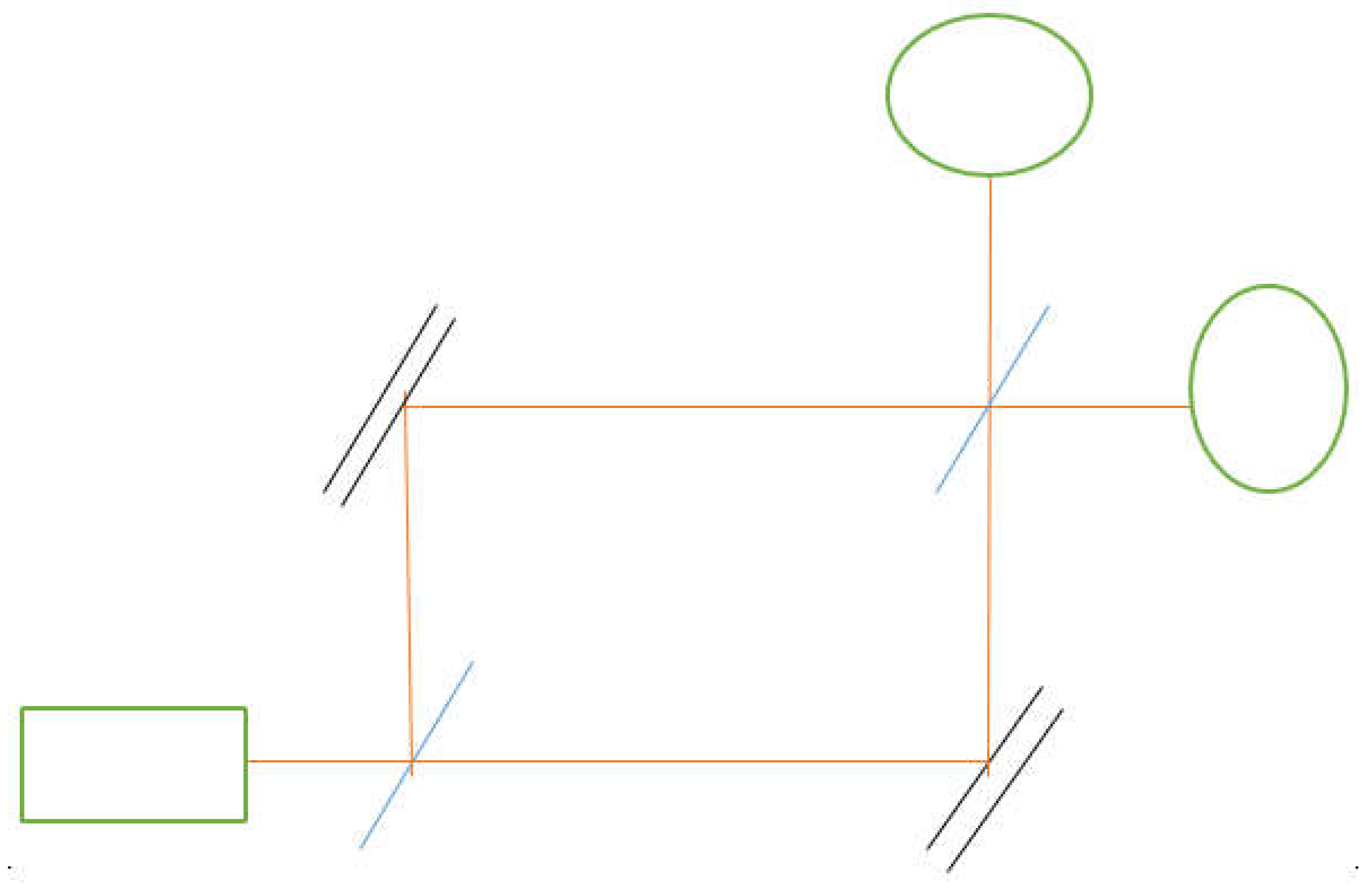
Two diagrams are given illustrating possible configurations for the proposed device.
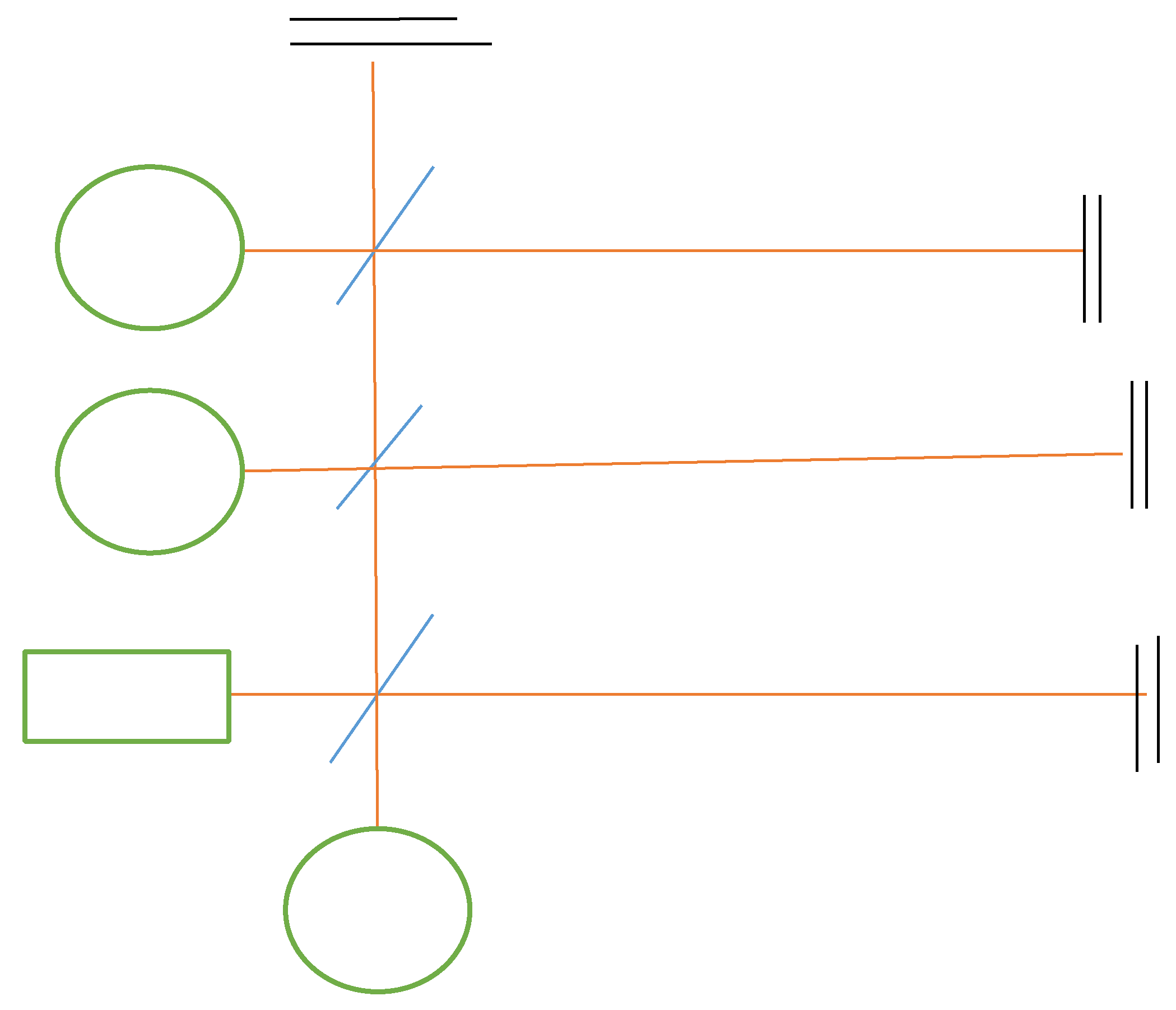
In Figure 3 it can be seen that the first beam splitter just after the light source splits the incoming beams from the source into two beams in perpendicular paths. Let one path be referred to as an x1 path; this is the path on vertical axis of the diagram, and the other path referred to as an x2 path on the horizontal axis of the diagram.
Figure 3.
Additional beam splitters in array are introduced between the beam splitter and the mirror in the x2 path, the number of beam splitters that can be added is not limited. But for the simplicity of the diagram only two additional beam splitters are used. The additional beam splitters may require adjustments of the distance between the first beam splitter and the mirror, likewise the gaps between the beam-splitters in the array would also have to be considered. Each additional beam splitters is splitting the beam in the x2 path further, and just like the first beam splitter, the additional beam splitters will also split the beams perpendicularly, into more x1 and x2 paths. All the beams in the x2 path will overlap in the same direction and still remain a single beam, but the new sets of x1 paths will be parallel to each other.
Like the Michelson interferometer, the beams in the x1 path will each be directed towards the mirrors in their paths, which then reflects them to their respective detectors. But before each of them must have intersected with the x2 beam leading to interference that will generate individual fringes for each interference which will be detected using the photo-detectors.
The phase difference for a single interference between two beams is typically given as;
∆𝜑 = 𝜑𝑥2 − 𝜑𝑥1
However the sum of phase differences for multiple interference would be;
𝜑𝑥2 − 𝜑𝑎𝑥1 + 𝜑𝑥2 − 𝜑𝑏𝑥1 + … 𝜑𝑥2 − 𝜑𝑛𝑥1
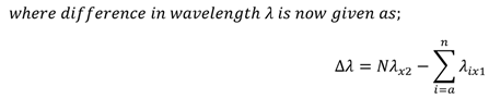
This sum would have to be redefined for the multiple x1 paths, and the single overlapped x2 path, that the phase difference for the multiple interference is;
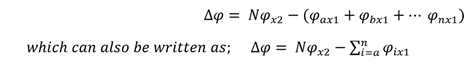
Where “N” is the number of interference.
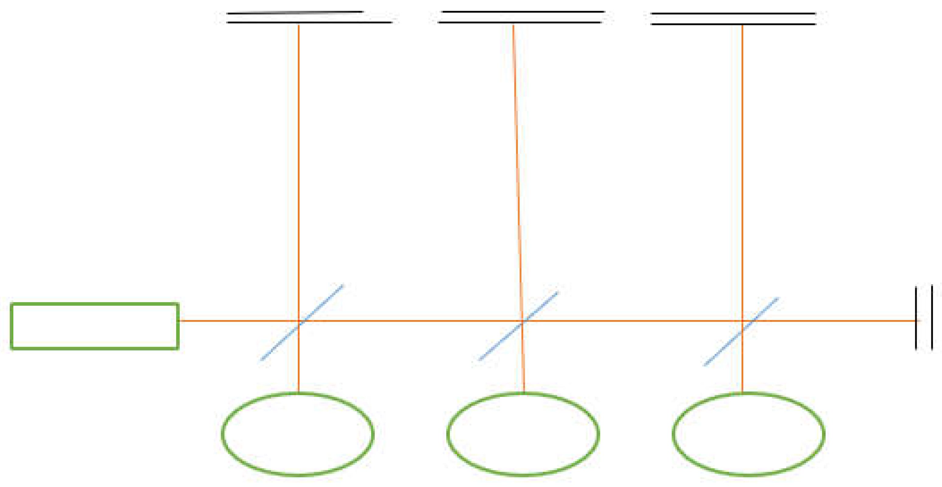
Figure 4 is another configuration but based on the same principle, the first beam splitter also splits the beams into two paths x1 and x2. However the additional beam splitters are on the x1 path, unlike the previous configuration where it’s on the x2 path. This leads to an overlapping of all the x1 beams in form of a single beam, and a parallel set of x2 beams, with mirrors and detectors for each x2 that would interfere with the x1 beam. Hence it can be said that;


Figure 4.
It is seen that both configurations still modifies the Michelson interferometer in the same manner but with different setups. These configurations would allow us to have multiple detectable fringes, providing separate patterns of interference that can be compared and analyzed, which may reveal more details of the interference, and may enhance sensitivity. It also gives us multiple choices of reference beams, or even allow us to have more than one reference beams at the same time.
5. Merits of the Reconfiguration in Instrumentation
The proposed interferometer would be an improvement to interferometry as instrumentation device. If one were to consider a parameter to be measured with an interferometer, and that parameter requires an interaction with the beams of a Michelson or a Mach Zehnder interferometer, the presence of the parameter would lead to a detectable, phase shifts between the beams. However these are just two beams, and the difference in their path length would be given as;
Though the difference in path length between the two beams and phase shifts incurred by an interaction with the given parameter can be sensed by the photodetector, but the difference in path length for n-number of coherent beams would be more pronounced.
The difference in path length for n-number of beams would be given as;
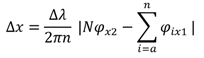
Leading us to; 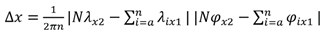
This optical path-length would be more noticeable to the detector, as the parameter is interacting with higher number of beams which are all at interference with the beam in the x2 direction. Enabling subtle phase changes from weaker signals to become more detectable.
The interferometer also allows relative detection of fringes, as individual detectors would be detecting individual fringes relative to other fringes. This way a parameter or sample can be studied or measured from different paths and perspectives. This is very useful for analysis as one can compare the data gotten from each detectors, revealing useful informations about the system.
Interferometric Instrumentation [10,11,12] involves measurement, detection and control of parameters, and the proposed interferometric system can been used to serve these purposes with greater capacity, particularly in terms of detection with high level of sensitivity and precision even for weak signal detection. It also has analytical advantage and freedom to vary the number of fringes according to experimental or practical needs, which is a level of control over the instrumentation system.
6. Adressable Limitations of the Reconfigured Michelson Interfrometer
The main limitation in implementing this reconfiguration is are the optical loss and weakening of beam as it passes through additional beam splitters, however to address this we ensure to use higher intensity beams in respect to the number beam splitters to be applied.
7. Conclusions
The Michelson and Mach Zehnder interferometer are already very versatile instrumentation devices, the proposed reconfiguration would further enhance instrumentation and find other areas of application especially in weak signal detection, comparative signal analysis and multi-resolution detection. It would be interesting to see it function in real time as there might be other merits it may have.
8. Declarations
I hereby declare that this article, titled; “Re-configuring the Michelson Interferometer for Multi-path Instrumentation”.
- Is written with no conflicting interest, neither is there any existing or pre-existing affiliation with any institution.
- No prior funds is received by the author from any organization, individual or institution.
- The content of the article is written with respect to ethics.
- The content of the article does not involve experimentation with human and/or animal subjects.
- Data-availability; no data, table or software prepared by an external body or institution is directly applicable to this article.
References
- Wikipedia.org. https://en.m.wikipedia.org/wiki/Michelson-Morley-experiment.
- R.S Shankland, Michelson-Morley experiment, American journal of physics, 32(1), 16-35, (1964).
- J. Lawal and E. Kessler, Michelson interferometry with 10pm accuracy, Review of Scientific Instruments, 71(7), 2669-2676, (2000).
- M. Ikram and G. Hussain, Michelson interferometer for precision angle measurements, Applied Optics, 38(1), 113-120, (1999).
- Alex Abramovici et-al, LIGO the Laser interferometer gravitational wave observatory, Science, 256(5055), 325333, (1992).
- Junaid Aasi, Thomas abbot et-al, Advanced LIGO, Classical and quantum gravity, 32(7), 074001, (2015).
- Gregory. M. Harry Advanced LIGO: the next generational wave detectors, Classical and quantum gravity, 27(8), 084006, (2010).
- S.F. Adams et-al. How does a Mach-Zender interferometer work? Physics Education, 35(1), 46, (2000).
- JG Rarity et-al, Two photon interference in a Mach-Zender interferometer, Physical review letters, 65(11), 1348, (1990).
- Shuming-Yang and Guofeng Zhang, A review of interferometry for geometric measurement, Measurement and science technology, 29(10), 102001, (2018).
- Silvano Donati, Developing self-mixing interferometry for instrumentation and measurements, Laser & Photonics reviews, 6(3), 393-417, (2012).
- Nicusor. V. iftima et-al. A portable low coherence interferometry based instrument for fine needle aspiration biopsy guidance, Review of scientific instruments, 76(6), (2005).
- Wikipedia.org. https://en.m.wikipedia.org/wiki/Optical-coherence-tomography-(OCT).
Disclaimer/Publisher’s Note: The statements, opinions and data contained in all publications are solely those of the individual author(s) and contributor(s) and not of MDPI and/or the editor(s). MDPI and/or the editor(s) disclaim responsibility for any injury to people or property resulting from any ideas, methods, instructions or products referred to in the content. |
© 2025 by the authors. Licensee MDPI, Basel, Switzerland. This article is an open access article distributed under the terms and conditions of the Creative Commons Attribution (CC BY) license (http://creativecommons.org/licenses/by/4.0/).
Copyright: This open access article is published under a Creative Commons CC BY 4.0 license, which permit the free download, distribution, and reuse, provided that the author and preprint are cited in any reuse.


