
Submitted:
07 March 2024
Posted:
08 March 2024
You are already at the latest version
Abstract
The progress in markerless technologies is bringing clinicians tools to rapidly evaluate tests such as Timed Up and Go (TUG) without compromising the time of the assessment, yet it raises questions about the potential trade-off in accuracy compared to traditional marker-based systems, suggesting that the precision of these evaluations is not yet conclusively established. The OpenCap system is an easy tool to process 3D kinematics with two iPhone cameras placed in front of the subject. Previous research has primarily focused on walking and movement towards the cameras with the subject facing the cameras (WF) and thus has been unable to disentangle the differences in the movement directions. We have compared the OpenCap system with a standard marker-based system for both walking directions. In OpenCap, we found significantly worse results capturing walking facing away from the cameras (RW). Compared to the marker-based system, our findings indicate troubles measuring kinematic parameters but provide good accuracy in measuring spatial-temporal parameters. These insights pave the way for refining markerless assessment technologies, potentially enhancing their utility in clinical settings.
Keywords:
OpenCap
; Markerless Gait Analysis
; Directional Bias in Motion Analysis
; Gait kinematics
; Smartphone-based Motion Capture
; Timed Up and Go (TUG) Test
1. Introduction
In clinical settings, quick and accurate tests are essential for patient care. The Timed Up and Go test (TUG), which assesses mobility and balance, is a crucial example. This test was initially developed by Podsiadlo and Richardson in 1991 [1] on the original version of the test named the “Get-up and Go,” which aimed to clinically evaluate dynamic balance in elderly people as proposed by Mathias et al. [2]. This test was further successfully tested on patients with multiple disorders [3,4,5]. The TUG test highly correlates with age, socioeconomic status, and multiple comorbidities [6]. To obtain even more information from the TUG test, recent developments in movement analysis, like wearables and markerless motion capture systems, offer a fast way to gather detailed movement data [7,8]. These new technologies could improve how we conduct and interpret tests like TUG without slowing down the assessment process and potentially enhance our understanding and measurement of such tests without compromising evaluation time [9]. TUG test can be further processed into individual sub-phases, such as standing up from the chair, walking, turning around, walking back, and sitting down. In those sub-phases, parameters such as the speed and the quality of movement were previously evaluated [10,11,12,13,14,15,16,17].
Markerless motion caption that uses standard video to record movement without markers. Its progress is based on recent advancements in deep learning techniques that identify body segment positions and orientation [18]. The OpenCap [19] is a recent addition to the markerless motion capture technology field. It distinguished itself by its accessibility and ease of use for measuring kinematics in real-world settings [19]. Unique for requiring only two iPhones to operate, OpenCap simplifies capturing human movement, making it broadly applicable in various settings. While it is a relatively new technology and not necessarily a major advancement, its accessibility opens up possibilities for broader applications, particularly in environments where traditional, more complex systems are not feasible. OpenCap’s potential in clinical and research contexts, especially for assessments like the TUG test, is currently being explored. Studies focus on its capabilities and limitations in accurately capturing and analyzing gait and mobility [20,21,22], underlining its emerging role in efficient and practical movement analysis.
The TUG test encompasses a range of activities, including standing from a seated position, walking, turning, and sitting down. Accurate recording of these varied movements is imperative for applying markerless systems within clinical environments.
Our study aims to comprehensively compare the system’s precision in capturing gait from various orientations, specifically comparing data when walking towards (WF – walk forward) and away from the cameras (RW - return walk), critically evaluating kinematic and spatial-temporal parameters. This examination is vital to thoroughly assess the OpenCap system’s full potential, focusing on its application in rapid evaluation tests such as the TUG test, shedding light on how much its ease of use and accessibility correspond with its accuracy and dependability in practical clinical settings.
2. Materials and Methods
Participants
Our study involved 9 healthy participants and one with hip osteoarthritis (left side), including 6 men. The average age of the participants was 29.7±8.6 (Maximum: 51, Minimum: 21) years, weight: 74±13 kg (Maximum: 90 kg, Minimum: 49 kg), height 176.6±11.5 cm (Maximum: 190 cm, Minimum: 160 cm ), BMI: 23.5±2 (Maximum: 25.4, Minimum: 18.9). All participants gave their written consent to participate in the study. The study was conducted in accordance with the Declaration of Helsinki, and the protocol was approved within a larger project by the Ethics Committee of University Hospital Bratislava (Approval number: 07/2020).
Measurement Setup
Our experimental setup took place in the gait laboratory at the Orthopaedics Hospital Speising in Vienna. In addition to capturing the TUG test, we separately recorded walking movements towards (WF) and away from the iPhone cameras (RW), which we focus on in this study. 5-7 recordings were conducted for each participant for each walking direction. Our methodology involved a dual-system approach, utilizing marker-based and markerless camera systems. For the markerless system, we set up the OpenCap system according to the recommended guidelines [23] with two iPhone cameras, an iPhone 12 and an iPhone 14. These were positioned on a tripod at the height of 1.5 meters, angled downwards by 5°. The iPhones were arranged to ensure that the center of the TUG area was squarely in the middle of both cameras’ capture zones. Additionally, the cameras were angled at 35° toward the center of the walking area (Figure 1). The starting position for the WF was initiated from a stationary stance at a distance of around 5.7 meters from the camera. Conversely, in RW, the initiation point was set at 2.7 meters from the camera. The recording stopped when the subject exited the recording area of the OpenCap system. OpenCap recorded the videos with default settings utilizing the OpenPose estimation algorithm, with a resolution of 720x1280 pixels and a frame rate of 60Hz. OpenCap’s embedded musculoskeletal model was from Lai et al. [24] and Rajagopal et al. [25], with modified hip abductor muscle paths, according to Uhlrich et al. [19]. The OpenCap version used was from November to December 2023. An optoelectronic motion capture system comprising 17 cameras (VICON, Oxford, UK) was employed for the marker-based measurement. Modified marker sets, specifically the Cleveland Clinical Marker Set (for the lower extremity) and the PlugIn Gait Model (upper extremity) [26], incorporating a total of markers, were utilized. The recording frequency was set at 150 Hz. Within the Nexus software (Version 2.15, Vicon, Oxford, UK), markers underwent reconstruction, filtering (Woltring Filter, Mean Squared Error [MSE], smoothing at 15 units), and subsequent storage. Notably, a seasoned user manually designated the events of Initial Contact (IC) and toe-off. The marker trajectories were then used to run OpenSim’s [27] inverse-kinematic tool with a musculoskeletal model from Rajagopal et al. [25].
Data Analysis
Data processing and statistical analysis were done using Matlab R2022b. The OpenCap data were processed using OpenCap’s web application [19]. First, we adjusted the signal from markerless data to match the marker-based system’s frequency by interpolating the data to 150 Hz and applying a Butterworth low-pass filter of 10 Hz. Data synchronization was achieved by aligning the peak flexion of the right knee, followed by cross-correlation to adjust the entire signal. Every measurement was then individually checked and corrected if needed. After the synchronization, we cut the signal from either system to obtain the same gait cycles from both systems. From each walking recording, we eliminated the first step. We normalized all joint kinematic variables of both systems to match the 100% gait cycle (GC).
We employed the Root Mean Square Error (RMSE) and Statistical Parametric Mapping (spm1d [28]) analysis for each joint kinematic variable, walking direction, and utilized system. We then extracted the kinematic and spatial-temporal parameters, averaged across the participants for the left and right sides. We utilized the Spearman correlation test in spatial-temporal and kinematic parameters across the two systems to assert the correlation.
3. Results
3.1. Comparing Walking Directions in the Markerless System
The comparison of averaged RMSE for left and right legs using markerless and marker-based systems reveals significant differences in kinematic analysis (Table 1). The markerless system shows a grand mean RMSE of 4.48±2.85°, while the marker-based system has a notably lower mean of 0.98±0.79°. Differences between the two systems are particularly notable in pelvic obliquity (5.8±2.0° vs. 0.3±0.2°), hip flexion (4.6±2.9° vs. 1.7±1.4°), hip abduction (6.6±3.9° vs 0.63±0.47°), hip rotation (3.6±2.5° vs 1.02±0.72°), knee flexion (3.6±2.5° vs. 1.3±1.2°), and ankle flexion (8.5±4.6° vs. 0.8±0.82°).
The analysis further details the RMSE for WF and RW directions between the two systems, emphasizing greater discrepancies in RW (grand mean 6.56±4.64° vs 4.88±3.3°), especially in pelvic obliquity(5.3±3.2° vs 2.8 ±2.1°), hip abduction (6.1± 4.2 °vs 3.5±2.5°), and ankle flexion (11.9±6.4° vs 4.7±3.4°). Table A1 demonstrates notable discrepancies in spatial-temporal and kinematic parameters between directions in the markerless system, with most variables showing differences greater than 3°. In contrast, Table A2, detailing the marker-based system, reveals smaller variations, with differences under 2°. Additionally, the markerless system lacks significant correlation across 18 kinematic parameters for both directions.
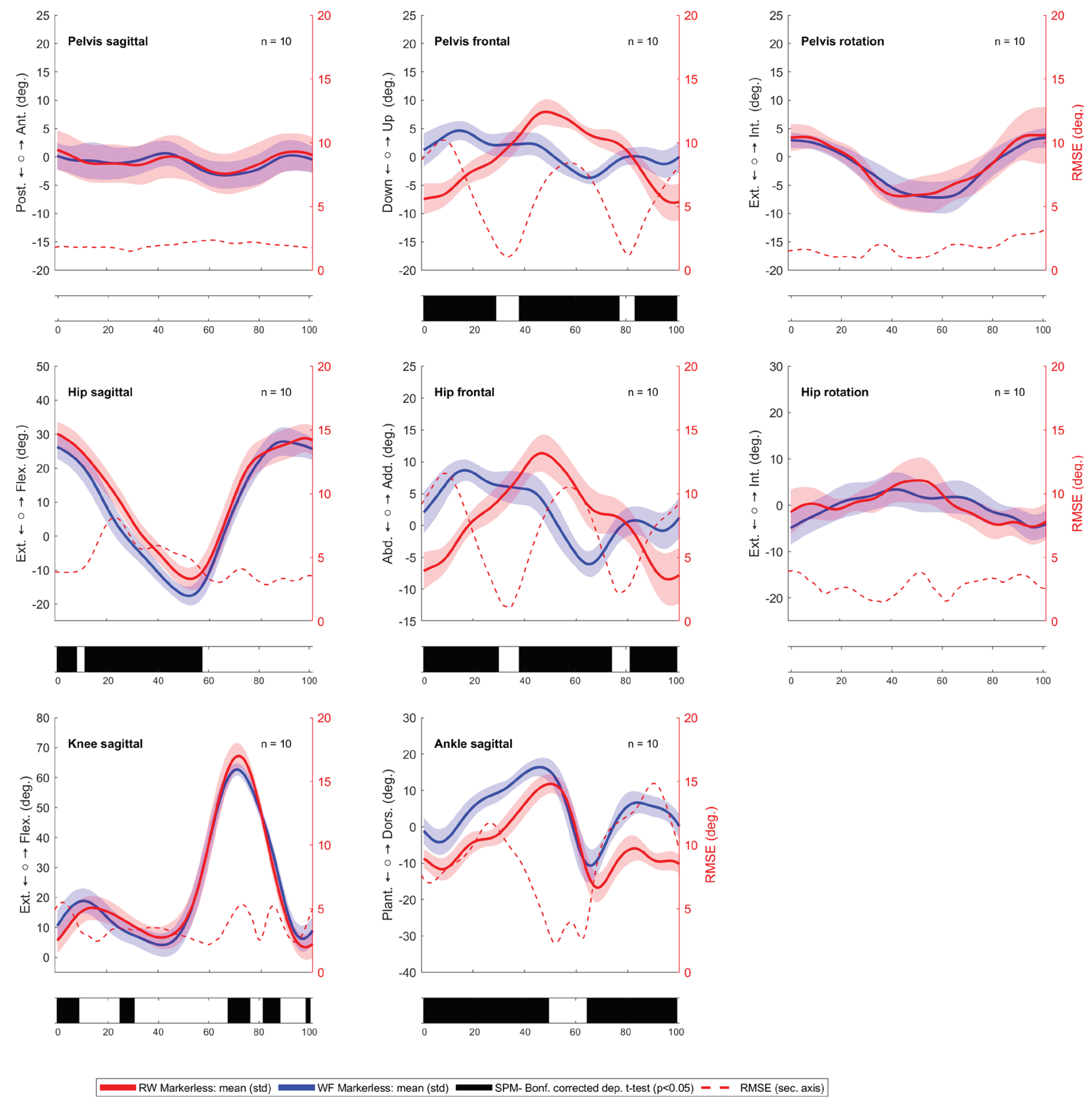
This difference is confirmed by observed kinematic analysis between WF and RW in the markerless system, as shown in the SPM1d analysis in Figure 1 for the right side (Figure A1 for the left side). We do not observe such differences in the marker-based system (Figure A2 and Figure A3).
Figure 2.
Kinematic comparison of the right GC between FW (blue line) and RW (red line) using the markerless system. Root Mean Square Error (RMSE) is shown as a red dotted line, and statistically significant differences, indicated by black bars beneath the respective kinematic signals, are determined by statistical parametric mapping (SPM1d) analysis at a significance level of p < 0.05.
3.2. Comparing the Markerless against the Marker-Based System
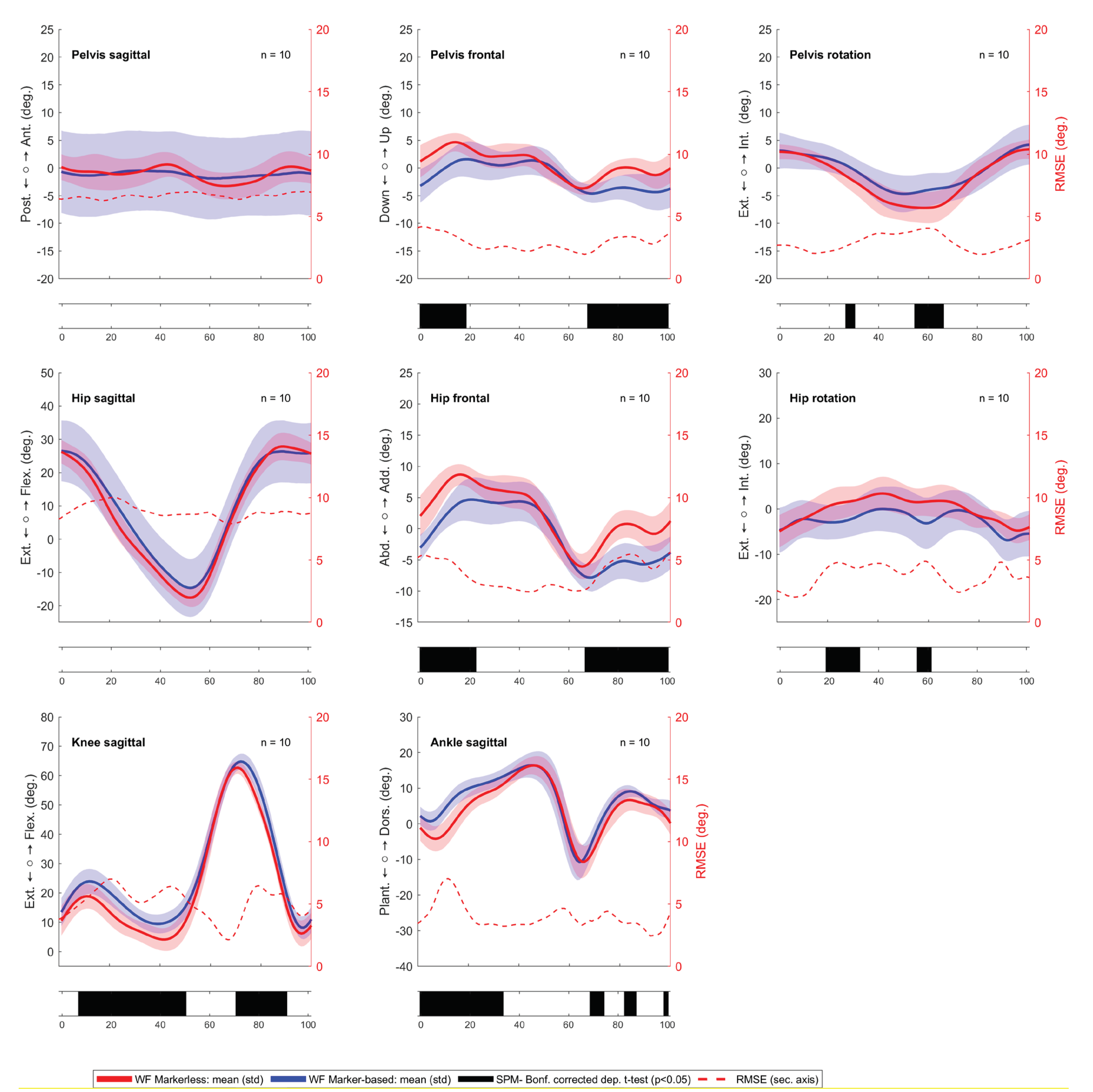
The kinematic plot with SPM analysis and RMSE conducted between the markerless and marker-based systems in WF revealed notable distinctions in the gait cycle’s dynamics, which are visible in Figure 3. For the right GC, we observed disparities in different phases of GC in the pelvic list, hip abduction, hip rotation, knee flexion, and ankle flexion. On the left side in Figure A4, we see a similar trend.
Additionally, in Table 2, when performing Spearman correlation of calculated kinematic variables between the marker-based system and markerless system for WF, we have only found significant correlations for both sides in only 2 out of 23 kinematic extracted parameters: hip flexion range of motion and hip rotation at initial contact. Some kinematic parameters show significant correlation only on one side: mean hip rotation during the stance phase, knee flexion range of motion, maximal plantar flexion, and angle lift-off. When evaluating the spatial-temporal parameters, the Spearman correlation in Table 2 showed a significant association for both legs, namely stride length (r=1; p < 0.001), step length (r=0.98; p < 0.001), and gait speed (r=1; p < 0.001). We also see a significant correlation with step width (0.94; p<0.001).
Similar, although slightly worse, results are visible for the RW in Figure A5 and Figure A6, where the comparison reveals different propagation of kinematics in the pelvic list, hip abduction, knee flexion, and ankle flexion. Compared to WF, the differences in RW seem to be more exaggerated, which is confirmed in Table A3, where the difference in hip obliquity ROM > 9° (<2° in WF), hip abduction ROM > 7° (<3° in WF), knee flexion ROM > 6° (<3° in WF), knee flexion at IC > 6° (3° in WF). We do not see a significant correlation for any kinematic parameters. Spatial-temporal parameters show significant correlations, similar to WF.
Figure 3.
Kinematic analysis comparing WF for the right GC using markerless (red line) and marker-based (blue line) systems, with the Root Mean Square Error (RMSE) shown as a red dotted line, and statistically significant differences, indicated by black bars beneath the respective kinematic signals, are determined by statistical parametric mapping (SPM1d) analysis at a significance level of p < 0.05.
3.3. Case section
In our comparative analysis of pelvis tracking data between marker-based and markerless systems, notable differences emerged in the standard deviations (STD) of the measurements. Specifically, the captured mean pelvic tilt in Table 2 displayed a larger standard deviation (7.2°) in the marker-based system, signifying a wider variability in pelvic movement. In contrast, data obtained from the markerless system demonstrated a smaller standard deviation in the mean pelvic tilt (2.4°), indicating more consistent pelvis movement data with less variability. While we see a wider range of pelvis tilt captured by the marker-based system (Figure 4), we do not observe the expected correlated values in the markerless system (the same is true for the left side). We will explore these findings through two case presentations.
3.3.1. Visible Lordosis
The first case illustrated in Figure 5 presents a participant with visible anterior pelvic tilt. The marker-based analysis, represented by the blue line in Figure 5, indicated a pelvic tilt of around 10 degrees visible over the whole gait cycle. Despite the apparent similarity in movement patterns, the markerless system fails to accurately capture anterior pelvic tilt, recording a value approximating 0°.
3.3.2. Pelvic Movement in a Participant with Hip Osteoarthritis
The second case presents the participant with advanced left hip osteoarthritis. His gait is not symmetrical, and he has reduced hip extension and compensatory movement in the pelvis. Looking at the pelvic movement from the markerless system in Figure 6, there is less anterior tilt of the pelvis at the end of the single support phase than in the marker-based data. The marker-based system shows less hip extension in the terminal stance phase. The markerless system presents a normal hip extension value. The ROM in the frontal plane in the pelvis and hip is greater with the markerless system, whereas the ROM is smaller in the transverse plane. From a clinical point of view, we would expect a reduced extension in the terminal stance phase for the participant, as seen by the marker-based system.
4. Discussion
The objective of the study was to assess and compare the outcomes of the markerless system while walking toward and away from the iPhone cameras. Specifically, we aimed to ensure uniformity in temporal-spatial parameters and kinematic results across both walking directions. The benchmark for this comparison was established using a marker-based system, where the kinematic data for both walking directions was anticipated to exhibit consistency. We conducted a comparative analysis of the directional movement results to gauge the concordance of data between the two systems.
The two walking directions in the TUG test, as shown by Bonnyaud et al. [10,11], do not present significant differences in the kinematic parameters for the hip, knee, and ankle in healthy and hemiparesis due to stroke. Due to the aim that we want to assess the accuracy of the markerless system to analyze the TUG test, the measurement system should be able to measure the same results between the FW and RW. First, we compared differences across all participants in the different walking directions. Overall, the RMSE between the two directions in the markerless system showed a mean difference of 4.47° across all the joints. Among those, we observed a clinically significant difference (>5 degrees) in pelvic obliquity: 5.75±3.26°, hip abduction: 6.6±3.92°, and ankle flexion: 8.51±4.59°. This high difference cannot be attributed to only different walking patterns of participants because the same measurement by the marker-based system recorded a grand mean RMSE of only 0,96°, and none of the joints presented an error higher than 2°. SPM analysis in the kinematics of joints highlighted these differences in the markerless system, showing significant differences in pelvic obliquity, hip abduction, hip flexion, knee flexion, and ankle flexion. When we compared the same gait cycles between the markerless and marker-based systems, we found lower RMSE values in WF, particularly in the pelvic obliquity (2.8° to 5.3° respectively), pelvic rotation ( 2.9° to 3.8° respectively), hip abduction (3.5° to 6.1° respectively), and ankle flexion (4.7° to 11.9° respectively). Max RMSE errors were also lower in WF. According to previous findings [18,29,30], there is a bias in pose estimation algorithms regarding the position and distances of the used cameras and currently available open-source training datasets that were never designed with biomechanical applications in mind. We can conclude that the errors observed in the markerless system related to directional differences are primarily due to less effective tracking when participants have their backs turned toward the iPhone cameras and walk away from the cameras.
We have further evaluated the markerless system compared to the marker-based system in WF’s kinematics and spatial-temporal parameters. The grand mean RMSE was 4.87, similar to the results from Horsak et al. [20], which was 4.61° without the subtalar joint (Horsak et al., 2023). The pelvis tilt and hip flexion in our measurements had slightly worse results. We recorded higher RMSE in the pelvic tilt at 8.94° (compared to 6.6°) and hip flexion at 5.4° (compared to 4.2°). However, the sole comparison of the RMSE does not tell us how the markerless system detects variability in different kinematic motions. We calculated a correlation between the markerless and the marker-based system for kinematic and spatial metrics. We found an excellent correlation in spatial-temporal metrics, especially measuring stride length, which was almost identical to the marker-based system (r=1; p<0.001) and a good correlation with the step width (r=0.94; p<0.001). When evaluating the kinematic parameters in Table 2, most of the parameters failed to record a significant correlation, meaning there could be a problem with how the kinematic curves change relative to individual participants.
These observations, notable the differences in the standard deviations (STD) between the markerless and marker-based system in the recording of the pelvic tilt, led us to examine the difference in the individual cases further. In the first case, a detailed examination of pelvic tilt revealed markerless’s problem detecting lordosis. We observed the markerless system’s tendency to report pelvic tilt measurements close to zero degrees, indicating a bias towards a neutral pelvic position. This standardization effect persisted even in case of significant lordosis, implying that the markerless system might not accurately represent deviations from neutral pelvic tilt. Given the coordinate definitions used in OpenSim calculations, while some underestimation compared to actual pelvic tilt is expected, a value around 0° suggests a considerable underrepresentation of actual pelvic tilt. The second case revealed markerless’s problem in capturing kinematic motion in a participant with advanced left hip osteoarthritis. This points to the markerless system’s lack of sensitivity in capturing nuanced gait dynamics, a critical aspect often necessary for clinical assessments.
It is crucial to acknowledge and address certain limitations, including small sample sizes, manual detection of gait events, different filtering, and the challenges in data synchronization. These factors could affect the precision of the analysis. Despite these limitations, our findings reveal robust differences. Addressing these issues would likely refine our results but not diminish the clear distinctions we have observed in the data.
5. Conclusions
In conclusion, while the OpenCap system offers promising accuracy in capturing spatial-temporal gait parameters such as step length and step width, its current limitations in providing comprehensive kinematic analysis cannot be overlooked. The comparison with the marker-based system has underscored these challenges, particularly in the variability based on walking direction and the challenges in the measurement of kinematics. For studies where pelvic movement is a key parameter, using markerless capture requires caution. WF and RW should be addressed when choosing the proposed camera setup for measuring the TUG test. Future research should focus on overcoming these limitations, potentially through improvement in pose estimation algorithms to enhance the reliability and applicability of the markerless systems in clinical gait analysis. Currently, marker-based systems have a clear advantage over markerless systems’ ability to consistently capture kinematic data.
Author Contributions
P.M. conducted the research design, data collection, data processing, statistical analysis, and manuscript writing. A.K. offered supervision, resource provision, and collaborated in the review and editing of the manuscript. A.K. also provided laboratory oversight for the data collection phase. Z.K. contributed to the review process and facilitated necessary administrative tasks. All authors have read and agreed to the published version of the manuscript.
Funding
The research stay was supported by the Aktion Österreich-Slowakei (AÖlK) Forschungsstipendien für Doktoranden under the auspices of the OeAD.
Institutional Review Board Statement
Available
Informed Consent Statement
Available
Data Availability Statement
On request
Acknowledgements
We want to express our gratitude to Tabea Schneider and Luc Adrians for their invaluable assistance in data collection. Additionally, our thanks go to FH-Prof. Priv.-Doz. Dr. Brian Horsak for providing the OpenSim models necessary for the Vicon calculations.
Declaration of Competing Interest
There is no conflict of interest to declare.
Appendix A
Figure A1.
Kinematic comparison between WF (red) and RW (blue) in the left leg in the markerless system. Root Mean Square Error (RMSE) is shown as a red dotted line, and statistically significant differences, indicated by black bars beneath the respective kinematic signals, are determined by statistical parametric mapping (SPM1d) analysis at a significance level of p < 0.05.
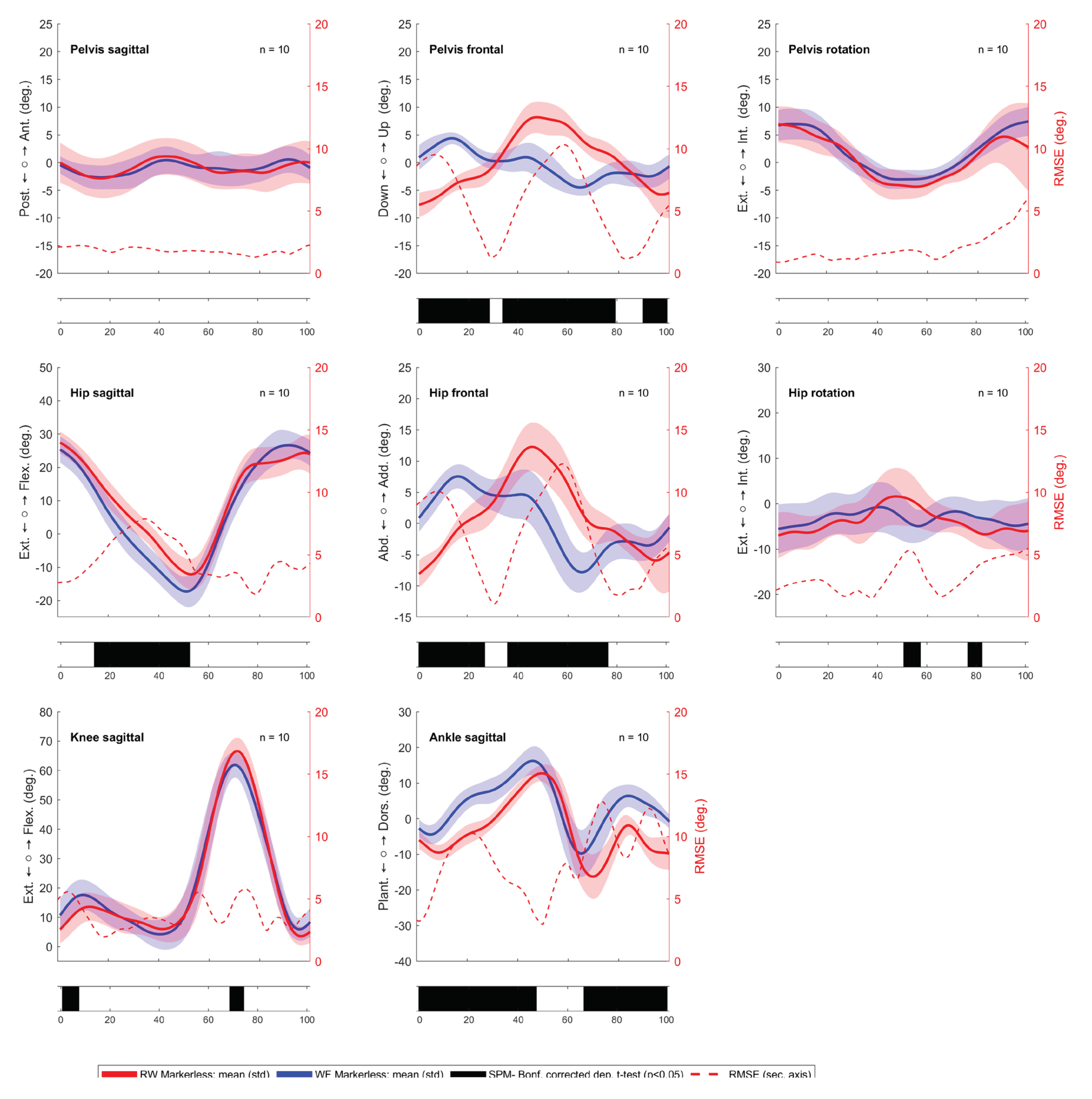
Figure A2.
Kinematic comparison between WF (red) and RW (blue) in the right leg in the marker-based system. Root Mean Square Error (RMSE) is shown as a red dotted line, and statistically significant differences, indicated by black bars beneath the respective kinematic signals, are determined by statistical parametric mapping (SPM1d) analysis at a significance level of p < 0.05.
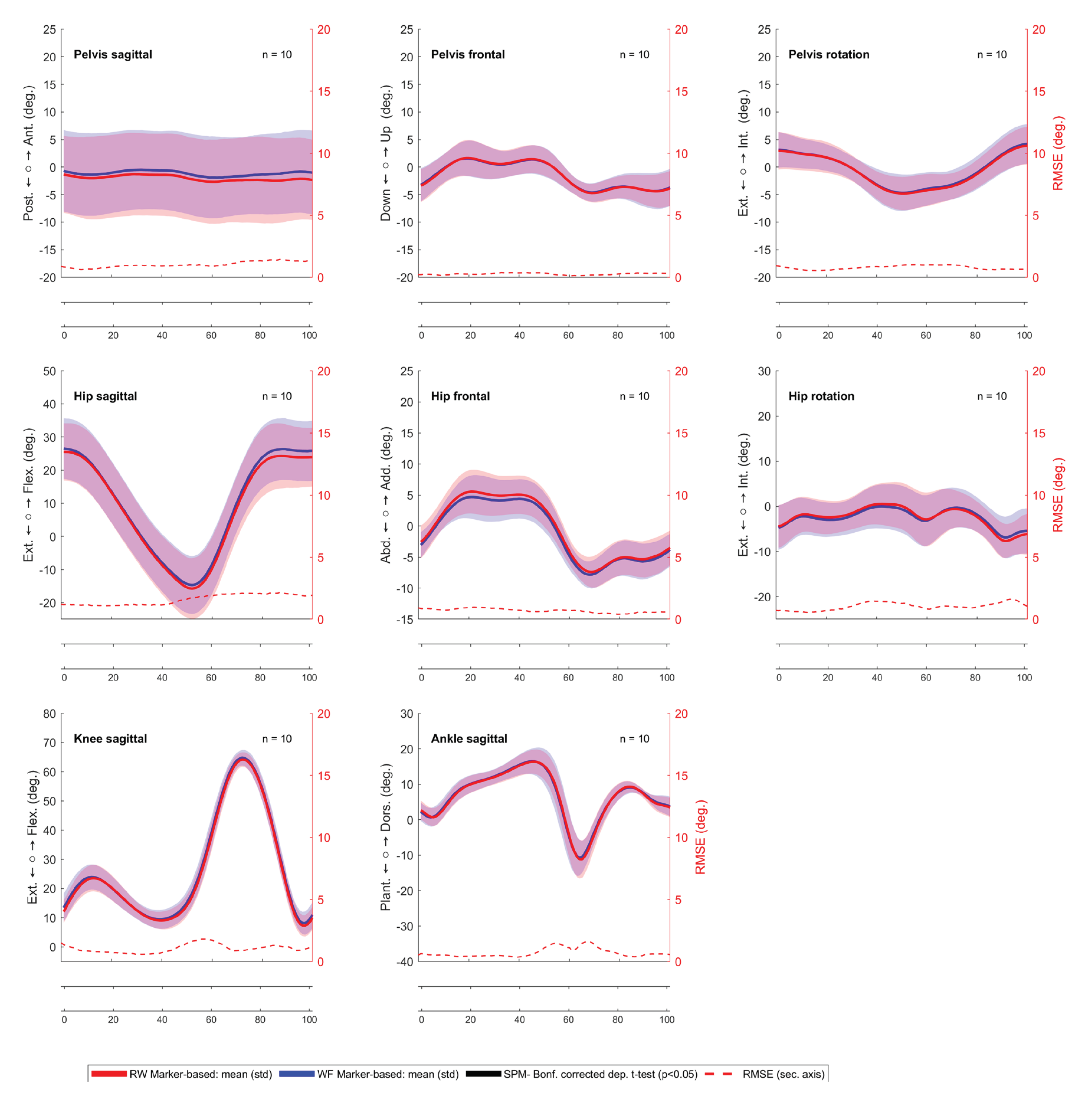
Figure A3.
Kinematic comparison between WF (red) and RW (blue) in the left leg in the marker-based system. Root Mean Square Error (RMSE) is shown as a red dotted line, and statistically significant differences, indicated by black bars beneath the respective kinematic signals, are determined by statistical parametric mapping (SPM1d) analysis at a significance level of p < 0.05.
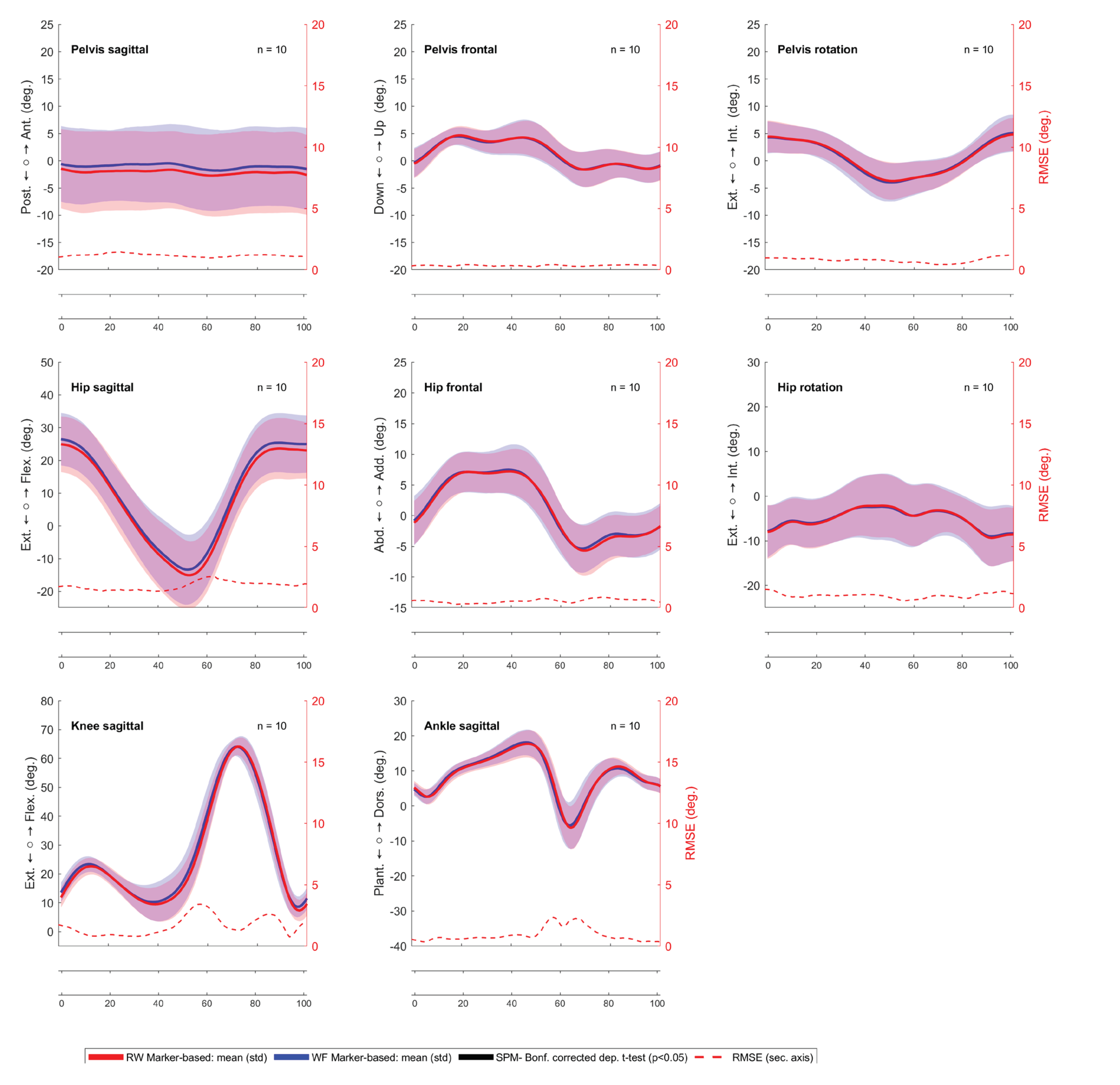
Figure A4.
Kinematic comparison between markerless (red line) and marker-based (blue line) in WF in the left leg, with the Root Mean Square Error (RMSE) shown as a red dotted line, and statistically significant differences, indicated by black bars beneath the respective kinematic signals, are determined by statistical parametric mapping (SPM1d) analysis at a significance level of p < 0.05.
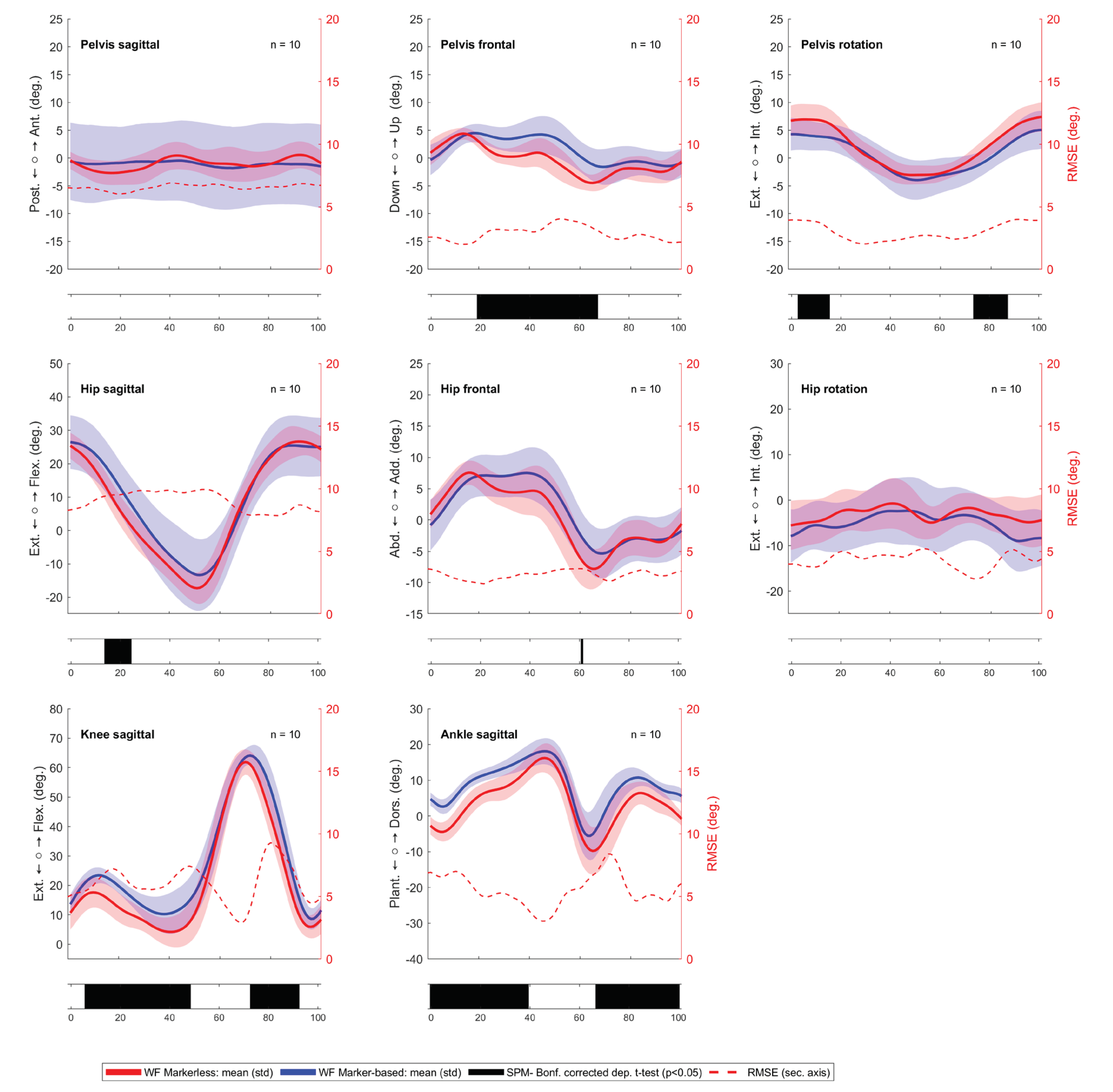
Figure A5.
Kinematic comparison between markerless (red line) and marker-based (blue line) in RW in the right leg, with the Root Mean Square Error (RMSE) shown as a red dotted line, and statistically significant differences, indicated by black bars beneath the respective kinematic signals, are determined by statistical parametric mapping (SPM1d) analysis at a significance level of p < 0.05.
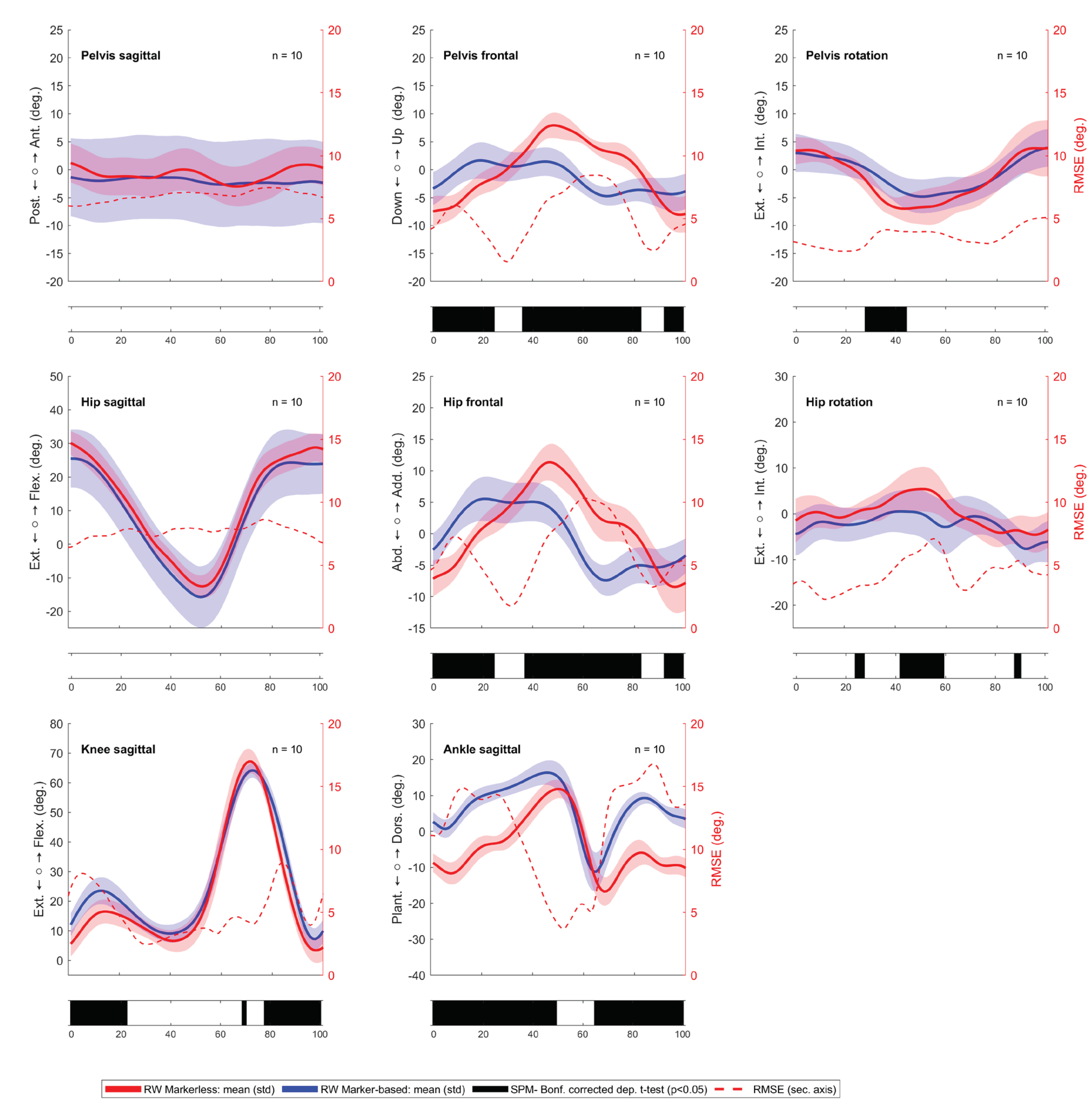
Figure A6.
Kinematic comparison between markerless (red line) and marker-based (blue line) in RW in the left leg, with the Root Mean Square Error (RMSE) shown as a red dotted line, and statistically significant differences, indicated by black bars beneath the respective kinematic signals, are determined by statistical parametric mapping (SPM1d) analysis at a significance level of p < 0.05.
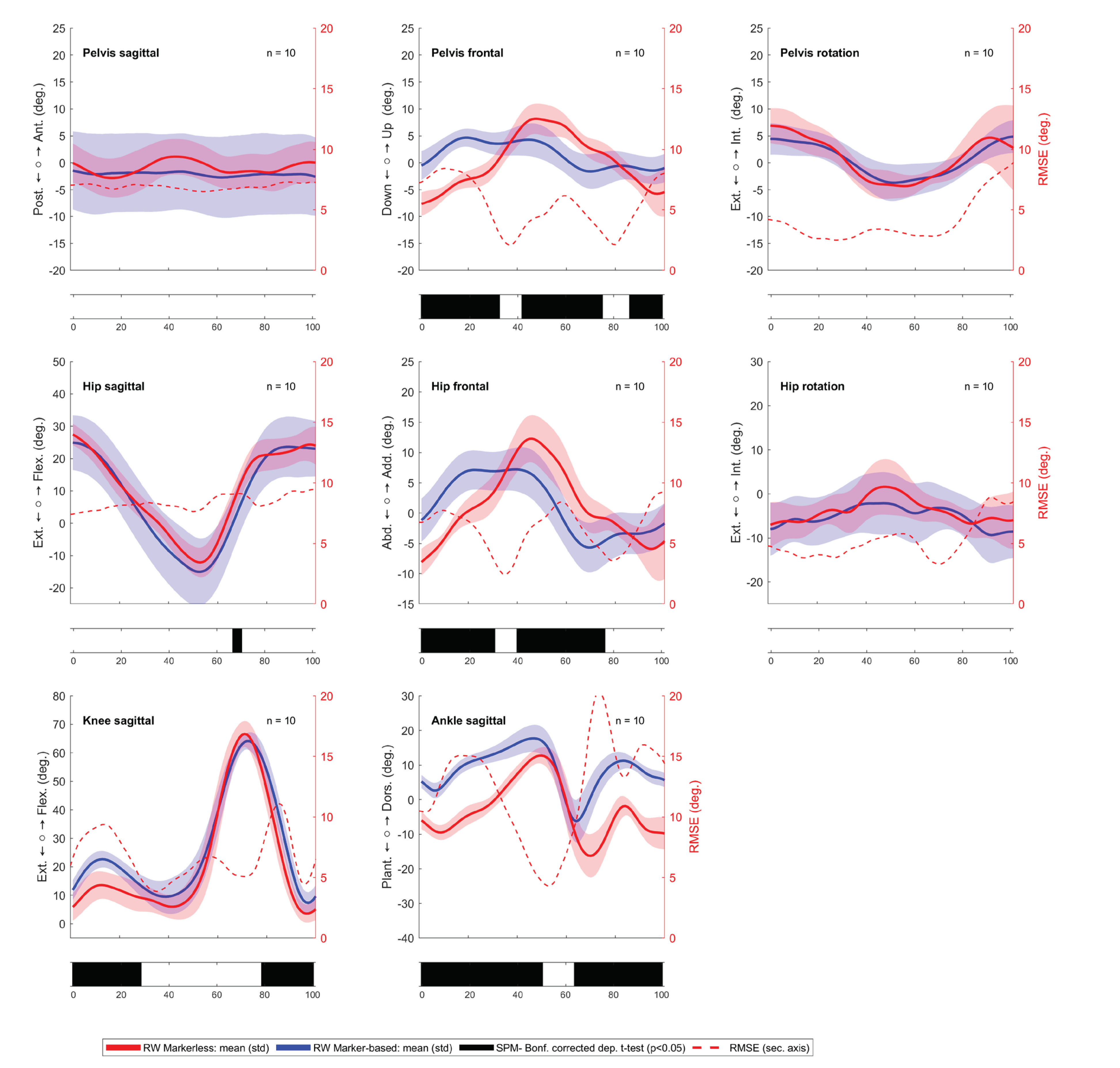

Table A1.
Kinematic parameters comparison between WF and RW in the markerless system.
| Parameter | WF | RW | Difference | Spearman correlation | ||||
|---|---|---|---|---|---|---|---|---|
| right | left | right | left | right | left | Right | left | |
| Mean (std) |
Mean (std) |
Mean (std) |
Mean (std) |
Mean (std) |
Mean (std) |
Corr (p-value) | Corr (p-value) | |
| Stride length (m) | 1.30 (0.12) | 1.30 (0.12) | 1.30 (0.12) | 1.28 (0.12) | 0.01 (0.02) | 0.02 (0.04) | 0.98 (<0.001) * | 0.89 (0.001) * |
| Step width (m) | 0.09 (0.02) | 0.09 (0.02) | 0.12 (0.02) | 0.11 (0.02) | 0.02 (0.01) | 0.02 (0.01) | 0.83 (0.01) * | 0.85 (0.004) * |
| Step length (m) | 0.65 (0.06) | 0.65 (0.06) | 0.63 (0.07) | 0.64 (0.06) | 0.02 (0.05) | 0.00 (0.01) | 0.68 (0.04) * | 0.96 (<0.001) * |
| Gait speed (m/s) | 1.23 (0.13) | 1.24 (0.14) | 1.21 (0.13) | 1.23 (0.14) | -0.02 (0.04) | 0.01 (0.02) | 0.92 (<0.001) * | 0.99 (<0.001) * |
| Pelvis tilt mean (°) | -1.0 (2.4) | -1.0 (2.3) | -0.8 (3.4) | -0.9 (3.3) | 0.18 (2.21) | 0.07 (2.02) | 0.61 (0.066) | 0.66 (0.044) * |
| Pelvis obliquity mean (°) | 0.7 (0.7) | -0.4 (0.6) | -0.0 (0.9) | 0.3 (0.6) | 0.69 (0.80) | 0.68 (0.64) | 0.43 (0.218) | 0.55 (0.104) |
| Pelvis obliquity ROM (°) | 9.6 (2.5) | 10.1 (2.4) | 17.4 (4.1) | 18.3 (3.6) | 7.77 (4.94) | 8.23 (3.65) | 0.14 (0.707) | 0.38 (0.279) |
| Pelvis obliquity IC (°) | 1.4 (2.9) | 1.1 (2.2) | -7.4 (2.7) | -7.6 (2.2) | 8.75 (1.81) | 8.72 (1.55) | 0.44 (0.204) | 0.68 (0.035) * |
| Pelvis rotation ROM (°) | 11.8 (2.7) | 11.7 (2.8) | 14.4 (3.5) | 17.4 (4.6) | 2.57 (3.15) | 5.62 (5.07) | 0.47 (0.178) | 0.14 (0.707) |
| Mean pelvis rotation(°) | -1.9 (1.7) | 2.0 (1.7) | -1.5 (2.1) | 0.9 (1.8) | 0.38 (1.34) | 1.09 (1.03) | 0.77 (0.014) * | 0.88 (0.002) * |
| Hip flexion ROM (°) | 46.9 (3.6) | 45.8 (6.7) | 43.9 (3.4) | 41.5 (5.7) | 2.95 (2.51) | 4.37 (3.27) | 0.79 (0.010) * | 0.84 (0.004) * |
| Hip flexion IC (°) | 26.0 (3.5) | 25.1 (3.9) | 29.9 (3.6) | 27.2 (3.3) | 3.85 (1.69) | 2.13 (3.65) | 0.92 (<0.001) * | 0.42 (0.232) |
| Hip sagittal - max extension (°) | -17.9 (2.8) | -18.0 (4.8) | -13.0 (3.0) | -13.0 (3.9) | 4.88 (2.77) | 5.01 (1.49) | 0.52 (0.133) | 0.92 (0.000) * |
| Hip Abduction ROM (°) | 15.7 (3.0) | 16.5 (3.5) | 21.2 (5.5) | 23.7 (4.2) | 5.54 (6.86) | 7.23 (4.74) | -0.02 (0.973) | 0.25 (0.492) |
| Hip Abduction IC (°) | 2.3 (3.2) | 1.2 (2.2) | -7.0 (2.8) | -7.9 (2.2) | 9.31 (2.73) | 9.07 (2.49) | 0.38 (0.279) | 0.12 (0.759) |
| Hip rotation ROM (°) | 11.7 (2.3) | 11.4 (2.3) | 15.2 (4.1) | 16.2 (3.5) | 3.45 (4.94) | 4.78 (3.90) | -0.24 (0.514) | 0.43 (0.218) |
| Hip rotation IC (°) | -4.8 (3.5) | -5.5 (5.4) | -1.3 (4.7) | -6.9 (5.0) | 3.47 (3.72) | 1.40 (3.50) | 0.50 (0.143) | 0.60 (0.073) |
| Mean hip rotation – stand phase (°) | -0.1 (3.3) | -3.1 (4.6) | 0.5 (2.8) | -4.7 (3.9) | 0.59 (2.19) | 1.55 (1.97) | 0.73 (0.021) * | 0.83 (0.006) * |
| Knee flexion ROM (°) | 60.3 (4.4) | 61.2 (4.2) | 65.2 (4.2) | 65.5 (3.7) | 4.93 (4.43) | 4.37 (3.43) | 0.71 (0.028) * | 0.43 (0.218) |
| Knee flexion IC (°) | 11.2 (5.1) | 11.3 (5.7) | 6.1 (4.3) | 6.3 (4.9) | 5.06 (2.67) | 4.94 (3.59) | 0.81 (0.008) * | 0.81 (0.008) * |
| Maximal Knee extension (°) | 4.2 (3.6) | 2.9 (2.4) | 4.6 (3.7) | 4.6 (4.0) | 0.38 (3.12) | 1.67 (3.16) | 0.53 (0.123) | 0.61 (0.066) |
| Maximal knee flexion (°) | 63.4 (2.0) | 63.4 (3.9) | 68.0 (4.2) | 67.8 (4.3) | 4.66 (3.33) | 4.46 (2.42) | 0.53 (0.123) | 0.66 (0.044) * |
| Ankle flexion ROM (°) | 29.3 (3.0) | 28.9 (5.2) | 30.9 (3.4) | 33.1 (4.4) | 1.59 (3.91) | 4.16 (7.65) | 0.22 (0.537) | -0.37 (0.296) |
| Ankle flexion IC (°) | -1.5 (3.7) | -3.0 (2.5) | -9.0 (2.6) | -6.3 (2.5) | 7.46 (1.65) | 3.25 (1.76) | 0.92 (<0.001) * | 0.81 (0.008) * |
| Maximum stance dorsiflexion (°) | 14.8 (2.7) | 13.8 (4.4) | 6.8 (3.5) | 7.4 (2.9) | 7.97 (3.11) | 6.40 (3.16) | 0.61 (0.066) | 0.61 (0.066) |
| Maximum swing dorsiflexion (°) | 16.8 (2.4) | 16.9 (3.8) | 12.2 (2.4) | 13.4 (2.0) | 4.62 (1.87) | 3.50 (2.86) | 0.72 (0.024) * | 0.67 (0.039) * |
| Maximum plantar flexion (°) | -12.3 (4.0) | -11.9 (6.3) | -18.7 (3.4) | -19.6 (4.8) | 6.41 (4.08) | 7.70 (7.45) | 0.19 (0.608) | -0.02 (0.973) |
| Foot progression angle (°) | 9.4 (3.7) | 10.6 (5.3) | 9.9 (4.8) | 7.5 (5.8) | 0.4 (4.0) | 3.1 (3.2) | 0.59 (0.08) | 0.75 (0.02) * |
| Angle lift off (°) | 60.7 (5.2) | 58.4 (4.2) | 58.6 (6.8) | 57.8 (7.8) | 2.2 (5.8) | 0.6 (8.0) | 0.62 (0.06) | 0.13 (0.73) |
| Angle Landing (°) | 13.7 (2.5) | 14.4 (2.6) | 8.6 (3.3) | 8.4 (4.6) | 5.2 (2.3) | 6.0 (4.8) | 0.65 (0.05) * | 0.02 (0.97) |
ROM - range of motion, IC- initial contact, * p-value < 0.05, bold letters indicate p-value<0.05 on both sides.
Table A2.
Kinematic parameters comparison between WF and RW in the marker-based system.
| Parameter | WF | RW | Difference | Spearman correlation | ||||
|---|---|---|---|---|---|---|---|---|
| right | left | right | left | right | left | Right | left | |
| Mean (std) |
Mean (std) |
Mean (std) |
Mean (std) |
Mean (std) |
Mean (std) |
Corr (p-value) | Corr (p-value) | |
| Stride length (m) | 1.31 (0.12) | 1.31 (0.13) | 1.30 (0.12) | 1.30 (0.12) | -0.01 (0.04) | -0.01 (0.04) | 0.94 (<0.001) * | 0.94 (<0.001) * |
| Step width (m) | 0.09 (0.02) | 0.10 (0.02) | 0.09 (0.02) | 0.09 (0.02) | -0.00 (0.01) | -0.01 (0.02) | 0.78 (0.01) * | 0.65 (0.05) * |
| Step length (m) | 0.65 (0.06) | 0.67 (0.07) | 0.65 (0.06) | 0.65 (0.06) | -0.01 (0.02) | -0.01 (0.02) | 0.95 (<0.001) * | 0.93 (<0.001) * |
| Gait speed (m/s) | 1.24 (0.15) | 1.25 (0.15) | 1.24 (0.14) | 1.23 (0.13) | -0.00 (0.03) | -0.01 (0.05) | 0.99 (<0.001) * | 0.92 (<0.001) * |
| Pelvis tilt mean (°) | -1.1 (7.2) | -1.0 (7.0) | -2.0 (7.4) | -2.1 (7.3) | 0.9 (0.8) | 1.1 (0.9) | 0.96 (<0.001) * | 0.96 (<0.001) * |
| Pelvis obliquity mean (°) | -1.5 (2.0) | 1.4 (2.0) | -1.5 (2.0) | 1.5 (2.0) | 0.0 (0.1) | 0.0 (0.2) | 1.00 (<0.001) * | 0.99 (<0.001) * |
| Pelvis obliquity ROM (°) | 8.3 (2.8) | 8.3 (2.9) | 8.3 (2.6) | 8.3 (2.6) | 0.0 (0.6) | 0.0 (0.7) | 0.95 (<0.001) * | 0.94 (<0.001) * |
| Pelvis obliquity IC (°) | -3.1 (3.0) | -0.2 (2.7) | -3.2 (3.0) | -0.4 (2.6) | 0.2 (0.2) | 0.2 (0.3) | 0.99 (<0.001) * | 0.99 (<0.001) * |
| Pelvis rotation ROM (°) | 11.3 (3.9) | 11.4 (3.7) | 11.0 (3.8) | 10.8 (4.0) | 0.2 (1.6) | 0.6 (1.5) | 0.87 (0.003)* | 0.87 (0.003) * |
| Mean pelvis rotation(°) | -0.5 (1.8) | 0.6 (2.0) | -0.7 (1.9) | 0.6 (1.8) | 0.1 (0.7) | 0.0 (0.7) | 0.77 (0.01) * | 0.78 (0.01) * |
| Hip flexion ROM (°) | 43.4 (4.6) | 41.2 (8.8) | 43.3 (5.0) | 41.4 (8.9) | 0.1 (1.7) | 0.1 (1.5) | 0.93 (<0.001) * | 0.94 (<0.001) * |
| Hip flexion IC (°) | 26.5 (9.2) | 26.4 (8.0) | 25.5 (8.6) | 24.9 (8.5) | 1.0 (1.1) | 1.5 (1.3) | 0.98 (<0.001) * | 0.99 (<0.001) * |
| Hip sagittal - max extension (°) | -15.0 (8.8) | -13.9 (10.6) | -16.1 (9.0) | -15.4 (10.3) | 1.0 (1.6) | 1.5 (1.3) | 0.95 (<0.001) * | 0.95 (<0.001) * |
| Hip Abduction ROM (°) | 13.7 (3.0) | 14.6 (4.0) | 14.1 (3.1) | 14.7 (3.9) | 0.4 (0.8) | 0.1 (1.0) | 0.94 (<0.001) * | 0.95 (<0.001) * |
| Hip Abduction IC (°) | -2.8 (2.0) | -0.6 (4.0) | -2.4 (2.6) | -1.0 (3.6) | 0.5 (1.0) | 0.4 (0.7) | 0.96 (<0.001) * | 0.98 (<0.001) * |
| Hip rotation ROM (°) | 11.5 (2.8) | 11.0 (3.4) | 12.7 (2.2) | 11.9 (3.4) | 1.2 (1.3) | 0.8 (0.7) | 0.85 (0.004) * | 0.92 (<0.001) * |
| Hip rotation IC (°) | -4.6 (4.9) | -7.8 (5.8) | -4.4 (4.7) | -8.0 (5.9) | 0.2 (0.8) | 0.2 (1.8) | 0.99 (<0.001) * | 0.95 (<0.001) * |
| Mean hip rotation – stand phase (°) | -2.4 (3.9) | -5.2 (5.6) | -1.9 (3.7) | -5.3 (5.6) | 0.5 (0.7) | 0.1 (1.2) | 0.89 (0.001) * | 0.92 (<0.001) * |
| Knee flexion ROM (°) | 58.5 (3.2) | 58.5 (4.0) | 58.3 (3.0) | 58.9 (3.8) | 0.2 (1.2) | 0.4 (1.0) | 0.87 (0.003) * | 0.95 (<0.001) * |
| Knee flexion IC (°) | 14.2 (4.8) | 14.3 (3.4) | 12.9 (3.9) | 12.6 (3.5) | 1.3 (1.5) | 1.7 (0.7) | 0.99 (<0.001) * | 0.94 (<0.001) * |
| Maximal Knee extension (°) | 8.7 (2.8) | 8.7 (3.8) | 8.6 (2.7) | 7.8 (3.6) | 0.1 (0.6) | 0.9 (1.0) | 0.96 (<0.001) * | 0.92 (<0.001) * |
| Maximal knee flexion (°) | 65.2 (2.6) | 65.3 (3.4) | 64.5 (2.6) | 64.8 (3.2) | 0.6 (0.9) | 0.5 (1.2) | 0.93 (<0.001) * | 0.90 (<0.001) * |
| Ankle flexion ROM (°) | 28.7 (4.0) | 25.9 (4.4) | 28.7 (4.0) | 25.5 (4.1) | 0.0 (1.1) | 0.3 (1.3) | 0.96 (<0.001) * | 0.96 (<0.001) * |
| Ankle flexion IC (°) | 1.9 (2.6) | 4.4 (1.8) | 2.4 (2.6) | 4.9 (1.9) | 0.5 (0.5) | 0.5 (0.4) | 0.90 (<0.001) * | 0.99 (<0.001) * |
| Maximum stance dorsiflexion (°) | 15.4 (3.0) | 16.9 (3.7) | 15.3 (3.1) | 16.3 (3.6) | 0.1 (0.4) | 0.6 (1.0) | 0.89 (0.001) * | 0.93 (<0.001) * |
| Maximum swing dorsiflexion (°) | 16.6 (3.9) | 18.4 (3.5) | 16.6 (3.4) | 18.0 (3.7) | 0.0 (0.9) | 0.4 (0.9) | 0.96 (<0.001) * | 0.95 (<0.001) * |
| Maximum plantar flexion (°) | -11.8 (5.1) | -7.4 (6.0) | -12.0 (5.1) | -7.4 (5.5) | 0.2 (1.3) | 0.0 (2.0) | 1.00 (<0.001) * | 0.93 (<0.001) * |
| Foot progression angle (°) | 10.2 (3.1) | 10.0 (5.3) | 9.4 (3.7) | 10.6 (5.3) | 0.80 (1.8) | 0.6 (1.4) | 0.88 (0.002) * | 0.96 (<0.001) * |
| Angle lift off (°) | 61.2 (5.3) | 60.7 (5.3) | 60.7 (5.2) | 58.4 (4.2) | 0.48 (2.8) | 2.27 (3.5) | 0.77 (0.01) * | 0.67 (0.04) * |
| Angle Landing (°) | 11.9 (3.8) | 12.4 (2.3) | 13.7 (2.5) | 14.4 (2.6) | 1.9 (2.5) | 2.0 (1.7) | 0.81 (0.01) * | 0.54 (0.11) |
ROM - range of motion, IC- initial contact, * p-value < 0.05, bold letters indicate p-value<0.05 on both sides.
Table A3.
Spatial-temporal and kinematic parameters for RW between markerless and marker-based system.
Table A3.
Spatial-temporal and kinematic parameters for RW between markerless and marker-based system.
| Parameter | Marker-based | Markerless | Difference | Spearman correlation | ||||
|---|---|---|---|---|---|---|---|---|
| right | left | right | left | right | left | Right | left | |
| Mean (std) |
Mean (std) |
Mean (std) |
Mean (std) |
Mean (std) |
Mean (std) |
Corr (p-value) | Corr (p-value) | |
| Stride length (m) | 1.30 (0.12) | 1.30 (0.12) | 1.30 (0.12) | 1.28 (0.12) | 0.01 (0.02) | 0.02 (0.04) | 0.98 (<0.001) * | 0.89 (0.001) * |
| Step width (m) | 0.09 (0.02) | 0.09 (0.02) | 0.12 (0.02) | 0.11 (0.02) | 0.02 (0.01) | 0.02 (0.01) | 0.83 (0.006) * | 0.85 (0.004) * |
| Step length (m) | 0.65 (0.06) | 0.65 (0.06) | 0.64 (0.06) | 0.63 (0.07) | -0.00 (0.01) | -0.02 (0.05) | 0.96 (<0.001) * | 0.68 (0.04) * |
| Gait speed (m/s) | 1.24 (0.14) | 1.23 (0.13) | 1.23 (0.14) | 1.21 (0.13) | -0.01 (0.02) | -0.02 (0.04) | 0.99 (<0.001) * | 0.92 (<0.001) * |
| Pelvis tilt mean (°) | -2.0 (7.4) | -2.1 (7.3) | -0.8 (3.4) | -0.9 (3.3) | 1.14 (7.76) | 1.16 (7.65) | 0.24 (0.514) | 0.14 (0.707) |
| Pelvis obliquity mean (°) | -1.5 (2.0) | 1.5 (2.0) | -0.0 (0.9) | 0.3 (0.6) | 1.48 (1.76) | 1.22 (1.99) | 0.52 (0.133) | 0.37 (0.296) |
| Pelvis obliquity ROM (°) | 8.3 (2.6) | 8.3 (2.6) | 17.4 (4.1) | 18.3 (3.6) | 10.0 (3.5) | 9.99 (3.53) | 0.60 (0.073) | 0.47 (0.178) |
| Pelvis obliquity IC (°) | -3.2 (3.0) | -0.4 (2.6) | -7.4 (2.7) | -7.6 (2.2) | 4.17 (3.19) | 7.20 (2.07) | 0.19 (0.608) | 0.64 (0.054) |
| Pelvis rotation ROM (°) | 11.0 (3.8) | 10.8 (4.0) | 14.4 (3.5) | 17.4 (4.6) | 3.33 (6.24) | 6.55 (5.52) | -0.47 (0.178) | 0.21 (0.560) |
| Mean pelvis rotation(°) | -0.7 (1.9) | 0.6 (1.8) | -1.5 (2.1) | 0.9 (1.8) | 0.80 (2.76) | 0.33 (2.19) | 0.07 (0.865) | 0.26 (0.470) |
| Hip flexion ROM (°) | 43.3 (5.0) | 41.4 (8.9) | 43.9 (3.4) | 41.5 (5.7) | 0.63 (4.80) | 0.11 (6.73) | 0.26 (0.470) | 0.66 (0.044) * |
| Hip flexion IC (°) | 25.5 (8.6) | 24.9 (8.5) | 29.9 (3.6) | 27.2 (3.3) | 4.40 (7.90) | 2.33 (7.59) | 0.42 (0.232) | 0.58 (0.088) |
| Hip sagittal - max extension (°) | -16.1 (9.0) | -15.4 (10.3) | -13.0 (3.0) | -13.0 (3.9) | 3.03 (8.25) | 2.40 (9.37) | 0.28 (0.427) | 0.45 (0.191) |
| Hip Abduction ROM (°) | 14.1 (3.1) | 14.7 (3.9) | 21.2 (5.5) | 23.7 (4.2) | 7.19 (3.60) | 9.01 (4.15) | 0.78 (0.012) * | 0.56 (0.096) |
| Hip Abduction IC (°) | -2.4 (2.6) | -1.0 (3.6) | -7.0 (2.8) | -7.9 (2.2) | 4.66 (3.12) | 6.93 (2.96) | 0.28 (0.427) | 0.50 (0.143) |
| Hip rotation ROM (°) | 12.7 (2.2) | 11.9 (3.4) | 15.2 (4.1) | 16.2 (3.5) | 2.50 (5.26) | 4.31 (4.89) | -0.30 (0.407) | 0.10 (0.785) |
| Hip rotation IC (°) | -4.4 (4.7) | -8.0 (5.9) | -1.3 (4.7) | -6.9 (5.0) | 3.07 (3.43) | 1.06 (5.16) | 0.66 (0.044) * | 0.48 (0.166) |
| Mean hip rotation – stand phase (°) | -1.9 (3.7) | -5.3 (5.6) | 0.5 (2.8) | -4.7 (3.9) | 2.45 (1.98) | 0.62 (4.58) | 0.90 (0.001) * | 0.59 (0.080) |
| Knee flexion ROM (°) | 58.3 (3.0) | 58.9 (3.8) | 65.2 (4.2) | 65.5 (3.7) | 6.91 (4.59) | 6.63 (5.03) | 0.03 (0.946) | 0.30 (0.407) |
| Knee flexion IC (°) | 12.9 (3.9) | 12.6 (3.5) | 6.1 (4.3) | 6.3 (4.9) | 6.75 (3.27) | 6.26 (3.12) | 0.78 (0.012) * | 0.61 (0.066) |
| Maximal Knee extension (°) | 8.6 (2.7) | 7.8 (3.6) | 4.6 (3.7) | 4.6 (4.0) | 4.00 (2.86) | 3.21 (3.16) | 0.73 (0.021) * | 0.36 (0.313) |
| Maximal knee flexion (°) | 64.5 (2.6) | 64.8 (3.2) | 68.0 (4.2) | 67.8 (4.3) | 3.51 (4.67) | 3.01 (5.29) | 0.04 (0.919) | -0.02 (0.973) |
| Ankle flexion ROM (°) | 28.7 (4.0) | 25.5 (4.1) | 30.9 (3.4) | 33.1 (4.4) | 2.26 (3.56) | 7.55 (5.77) | 0.53 (0.123) | 0.02 (0.973) |
| Ankle flexion IC (°) | 2.4 (2.6) | 4.9 (1.9) | -9.0 (2.6) | -6.3 (2.5) | 11.39 (2.29) | 11.22 (3.71) | 0.43 (0.218) | -0.35 (0.331) |
| Maximum stance dorsiflexion (°) | 15.3 (3.1) | 16.3 (3.6) | 6.8 (3.5) | 7.4 (2.9) | 8.51 (4.00) | 8.88 (3.09) | 0.19 (0.608) | 0.31 (0.387) |
| Maximum swing dorsiflexion (°) | 16.6 (3.4) | 18.0 (3.7) | 12.2 (2.4) | 13.4 (2.0) | 4.36 (3.46) | 4.63 (3.33) | 0.33 (0.349) | 0.52 (0.133) |
| Maximum plantar flexion (°) | -12.0 (5.1) | -7.4 (5.5) | -18.7 (3.4) | -19.6 (4.8) | 6.67 (5.20) | 12.23 (6.68) | 0.04 (0.919) | -0.13 (0.733) |
| Foot progression angle (°) | 9.4 (3.7) | 10.6 (5.3) | 9.9 (4.8) | 7.5 (5.8) | 0.4 (4.0) | 3.1 (3.2) | 0.59 (0.08) | 0.75 (0.02) * |
| Angle lift off (°) | 60.7 (5.2) | 58.4 (4.2) | 58.6 (6.8) | 57.8 (7.8) | 2.2 (5.8) | 0.6 (8.0) | 0.62 (0.06) | 0.13 (0.73) |
| Angle Landing (°) | 13.7 (2.5) | 14.4 (2.6) | 8.6 (3.3) | 8.4 (4.6) | 5.2 (2.3) | 6.0 (4.8) | 0.65 (0.05) * | 0.02 (0.97) |
ROM - range of motion, IC- initial contact, * p-value < 0.05, bold letters indicate p-value<0.05 on both sides.
References
- Podsiadlo, D.; Richardson, S. The Timed “Up & Go”: A Test of Basic Functional Mobility for Frail Elderly Persons. J. Am. Geriatr. Soc. 1991, 39, 142–148. [Google Scholar] [CrossRef]
- Mathias, S.; Nayak, U.S.; Isaacs, B. Balance in Elderly Patients: The “Get-up and Go” Test. Arch. Phys. Med. Rehabil. 1986, 67, 387–389. [Google Scholar]
- Graff, K.; Szczerbik, E.; Kalinowska, M.; Kaczmarczyk, K.; Stępień, A.; Syczewska, M. Using the TUG Test for the Functional Assessment of Patients with Selected Disorders. Int. J. Environ. Res. Public. Health 2022, 19, 4602. [Google Scholar] [CrossRef]
- Komodikis, G.; Gannamani, V.; Neppala, S.; Li, M.; Merli, G.J.; Harrop, J.S. Usefulness of Timed Up and Go (TUG) Test for Prediction of Adverse Outcomes in Patients Undergoing Thoracolumbar Spine Surgery. Neurosurgery 2020, 86, E273–E280. [Google Scholar] [CrossRef]
- Luque-Casado, A.; Novo-Ponte, S.; Sánchez-Molina, J.A.; Sevilla-Sánchez, M.; Santos-García, D.; Fernández-del-Olmo, M. Test-Retest Reliability of the Timed Up and Go Test in Subjects with Parkinson’s Disease: Implications for Longitudinal Assessments. J. Park. Dis. 2021, 11, 2047–2055. [Google Scholar] [CrossRef]
- Kear, B.M.; Guck, T.P.; McGaha, A.L. Timed Up and Go (TUG) Test: Normative Reference Values for Ages 20 to 59 Years and Relationships With Physical and Mental Health Risk Factors. J. Prim. Care Community Health 2017, 8, 9–13. [Google Scholar] [CrossRef]
- Ortega-Bastidas, P.; Gómez, B.; Aqueveque, P.; Luarte-Martínez, S.; Cano-de-la-Cuerda, R. Instrumented Timed Up and Go Test (iTUG)—More Than Assessing Time to Predict Falls: A Systematic Review. Sensors 2023, 23, 3426. [Google Scholar] [CrossRef]
- Ponciano, V.; Pires, I.M.; Ribeiro, F.R.; Spinsante, S. Sensors Are Capable to Help in the Measurement of the Results of the Timed-Up and Go Test? A Systematic Review. J. Med. Syst. 2020, 44, 199. [Google Scholar] [CrossRef]
- Chen, S.; Lach, J.; Lo, B.; Yang, G.-Z. Toward Pervasive Gait Analysis With Wearable Sensors: A Systematic Review. IEEE J. Biomed. Health Inform. 2016, 20, 1521–1537. [Google Scholar] [CrossRef]
- Bonnyaud, C.; Pradon, D.; Vuillerme, N.; Bensmail, D.; Roche, N. Spatiotemporal and Kinematic Parameters Relating to Oriented Gait and Turn Performance in Patients with Chronic Stroke. PloS One 2015, 10, e0129821. [Google Scholar] [CrossRef]
- Bonnyaud, C.; Pradon, D.; Vaugier, I.; Vuillerme, N.; Bensmail, D.; Roche, N. Timed Up and Go Test: Comparison of Kinematics between Patients with Chronic Stroke and Healthy Subjects. Gait Posture 2016, 49, 258–263. [Google Scholar] [CrossRef]
- Hollands, K.L.; Hollands, M.A.; Zietz, D.; Wing, A.M.; Wright, C.; van Vliet, P. Kinematics of Turning 180 Degrees during the Timed up and Go in Stroke Survivors with and without Falls History. Neurorehabil. Neural Repair 2010, 24, 358–367. [Google Scholar] [CrossRef]
- Li, T.; Chen, J.; Hu, C.; Ma, Y.; Wu, Z.; Wan, W.; Huang, Y.; Jia, F.; Gong, C.; Wan, S.; et al. Automatic Timed Up-and-Go Sub-Task Segmentation for Parkinson’s Disease Patients Using Video-Based Activity Classification. IEEE Trans. Neural Syst. Rehabil. Eng. Publ. IEEE Eng. Med. Biol. Soc. 2018, 26, 2189–2199. [Google Scholar] [CrossRef]
- Salarian, A.; Horak, F.B.; Zampieri, C.; Carlson-Kuhta, P.; Nutt, J.G.; Aminian, K. iTUG, a Sensitive and Reliable Measure of Mobility. IEEE Trans. Neural Syst. Rehabil. Eng. Publ. IEEE Eng. Med. Biol. Soc. 2010, 18, 303–310. [Google Scholar] [CrossRef]
- Spina, S.; Facciorusso, S.; D’Ascanio, M.C.; Morone, G.; Baricich, A.; Fiore, P.; Santamato, A. Sensor Based Assessment of Turning during Instrumented Timed Up and Go Test for Quantifying Mobility in Chronic Stroke Patients. Eur. J. Phys. Rehabil. Med. 2023, 59, 6–13. [Google Scholar] [CrossRef]
- Van Uem, J.M.T.; Walgaard, S.; Ainsworth, E.; Hasmann, S.E.; Heger, T.; Nussbaum, S.; Hobert, M.A.; Micó-Amigo, E.M.; Van Lummel, R.C.; Berg, D.; et al. Quantitative Timed-Up-and-Go Parameters in Relation to Cognitive Parameters and Health-Related Quality of Life in Mild-to-Moderate Parkinson’s Disease. PloS One 2016, 11, e0151997. [Google Scholar] [CrossRef]
- Wall, J.C.; Bell, C.; Campbell, S.; Davis, J. The Timed Get-up-and-Go Test Revisited: Measurement of the Component Tasks. J. Rehabil. Res. Dev. 2000, 37, 109–113. [Google Scholar]
- Wade, L.; Needham, L.; McGuigan, P.; Bilzon, J. Applications and Limitations of Current Markerless Motion Capture Methods for Clinical Gait Biomechanics. PeerJ 2022, 10, e12995. [Google Scholar] [CrossRef]
- Uhlrich, S.D.; Falisse, A.; Kidziński, Ł.; Muccini, J.; Ko, M.; Chaudhari, A.S.; Hicks, J.L.; Delp, S.L. OpenCap: Human Movement Dynamics from Smartphone Videos. PLOS Comput. Biol. 2023, 19, e1011462. [Google Scholar] [CrossRef]
- Horsak, B.; Eichmann, A.; Lauer, K.; Prock, K.; Krondorfer, P.; Siragy, T.; Dumphart, B. Concurrent Validity of Smartphone-Based Markerless Motion Capturing to Quantify Lower-Limb Joint Kinematics in Healthy and Pathological Gait. J. Biomech. 2023, 159, 111801. [Google Scholar] [CrossRef]
- Lima, Y.; Collings, T.; Hall, M.; Bourne, M.; Diamond, L. Assessing Lower-Limb Kinematics via OpenCap during Dynamic Tasks Relevant to Anterior Cruciate Ligament Injury: A Validity Study. J. Sci. Med. Sport 2023, 26, S105. [Google Scholar] [CrossRef]
- Rodacki, A.L.F.; Buckley, J.G.; Passos de Oliveira, A.C.; Marçal da Silva, R.; Bertoli Nascimento, V. An Experimental Approach to Induce Trips in Lower-Limb Amputees. J. Vis. Exp. JoVE 2023. [Google Scholar] [CrossRef]
- OpenCap - Musculoskeletal Forces from Smartphone Videos. Available online: https://www.opencap.ai/ (accessed on 27 February 2024).
- Lai, A.K.M.; Arnold, A.S.; Wakeling, J.M. Why Are Antagonist Muscles Co-Activated in My Simulation? A Musculoskeletal Model for Analysing Human Locomotor Tasks. Ann. Biomed. Eng. 2017, 45, 2762–2774. [Google Scholar] [CrossRef]
- Rajagopal, A.; Dembia, C.L.; DeMers, M.S.; Delp, D.D.; Hicks, J.L.; Delp, S.L. Full-Body Musculoskeletal Model for Muscle-Driven Simulation of Human Gait. IEEE Trans. Biomed. Eng. 2016, 63, 2068–2079. [Google Scholar] [CrossRef]
- Svoboda, B.; Kranzl, A. A Study of the Reproducibility of the Marker Application of the Cleveland Clinic Marker Set Including the Plug-In Gait Upper Body Model in Clinical Gait Analysis. Gait Posture 2012, 36, S62–S63. [Google Scholar] [CrossRef]
- Delp, S.L.; Anderson, F.C.; Arnold, A.S.; Loan, P.; Habib, A.; John, C.T.; Guendelman, E.; Thelen, D.G. OpenSim: Open-Source Software to Create and Analyze Dynamic Simulations of Movement. IEEE Trans. Biomed. Eng. 2007, 54, 1940–1950. [Google Scholar] [CrossRef]
- Pataky, T.C. One-Dimensional Statistical Parametric Mapping in Python. Comput. Methods Biomech. Biomed. Engin. 2012, 15, 295–301. [Google Scholar] [CrossRef]
- Rapczyński, M.; Werner, P.; Handrich, S.; Al-Hamadi, A. A Baseline for Cross-Database 3D Human Pose Estimation. Sensors 2021, 21, 3769. [Google Scholar] [CrossRef]
- Sugiyama, Y.; Uno, K.; Matsui, Y. Types of Anomalies in Two-Dimensional Video-Based Gait Analysis in Uncontrolled Environments. PLOS Comput. Biol. 2023, 19, e1009989. [Google Scholar] [CrossRef]
Figure 1.
The schema of the motion capture setup - A markerless system used two iPhone cameras placed at a distance of 4.8 meters from each other at an angle of 35 degrees to the center of the walking area, which was 3 meters long. The marker-based setup employed 17 Vicon cameras surrounding the central walkway. One side marks the beginning of walking towards the iPhone cameras (WF Start), while the opposite side signifies the start of walking away from them (RW Start).
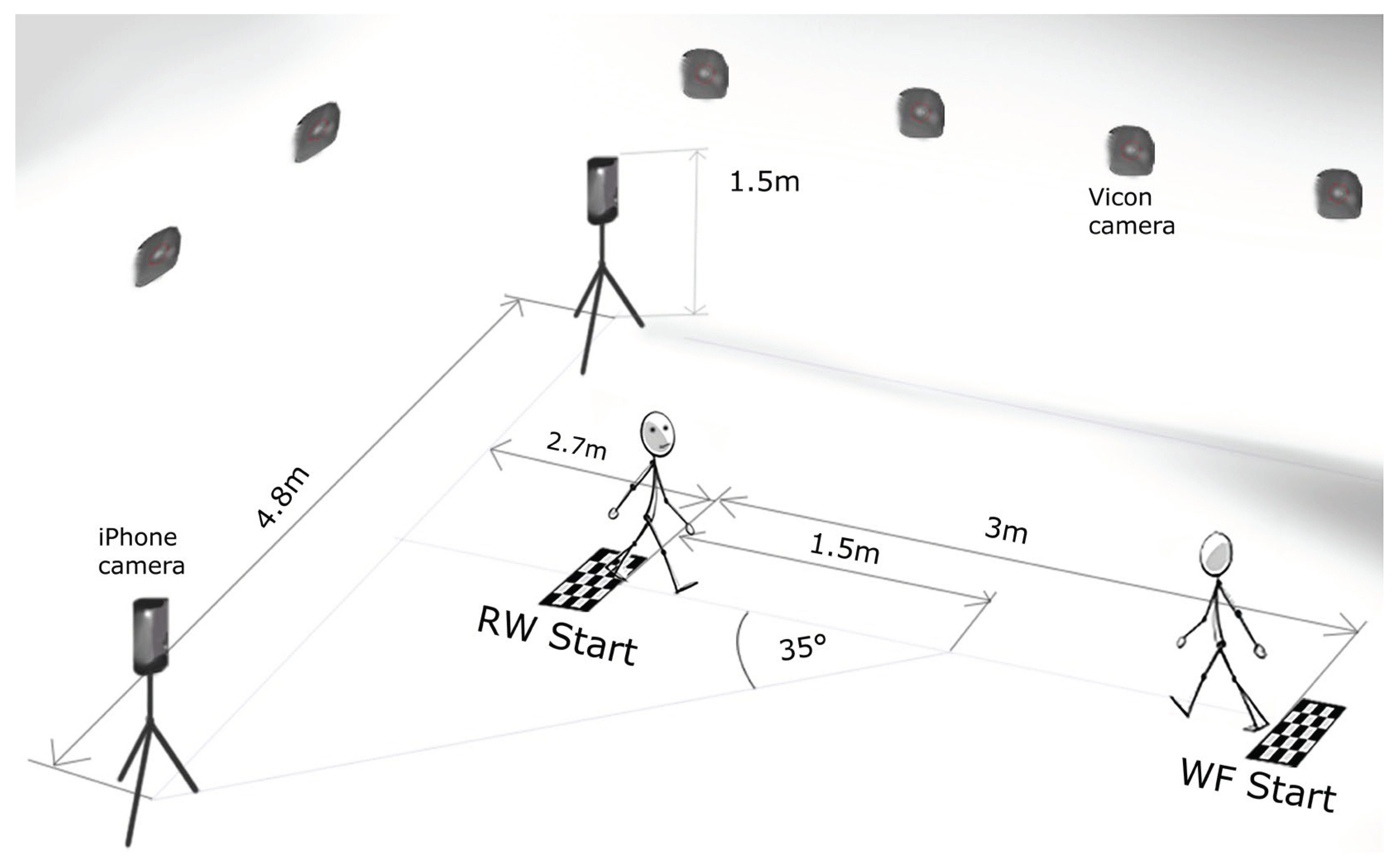
Figure 4.
Mean pelvic tilt on the right side during the whole GC- comparison between the marker-based and the OpenCap system for each participant.
Figure 4.
Mean pelvic tilt on the right side during the whole GC- comparison between the marker-based and the OpenCap system for each participant.
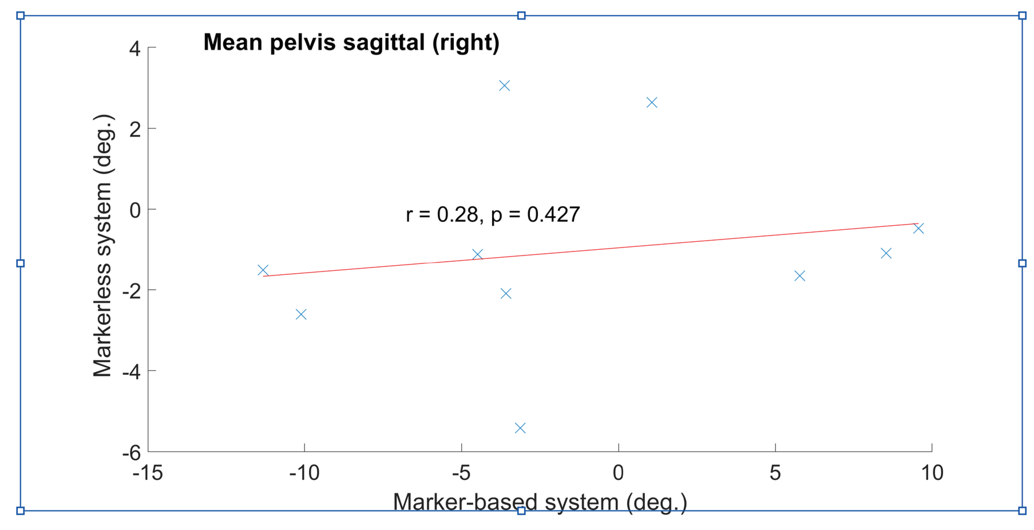
Figure 5.
(a) Sagittal view of the pelvis (b) the movement of pelvic tilt during right GC: marker-based (blue line) compared to markerless (red line).
Figure 5.
(a) Sagittal view of the pelvis (b) the movement of pelvic tilt during right GC: marker-based (blue line) compared to markerless (red line).
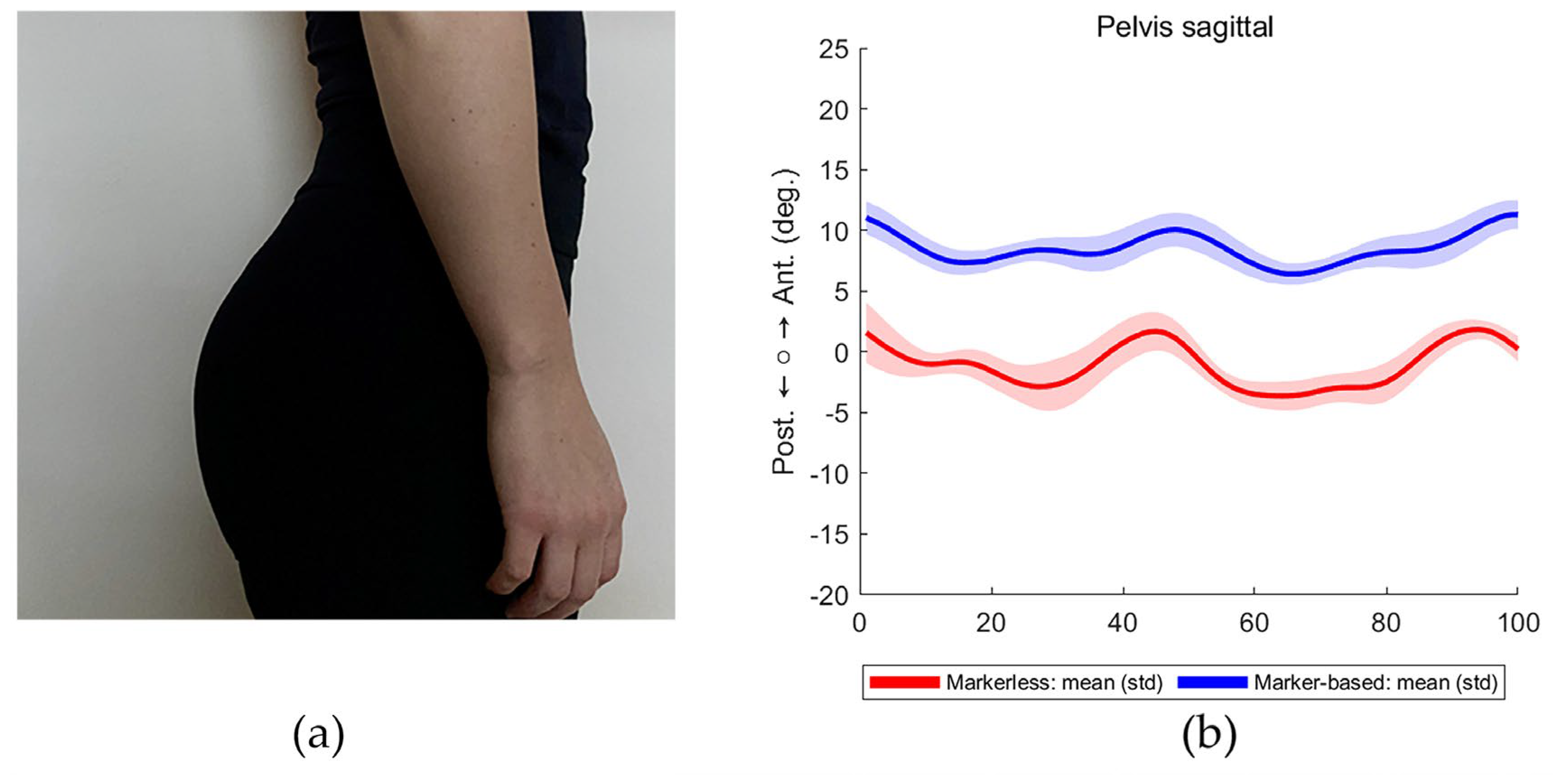
Figure 6.
Pelvic and hip movement (left side) of marker-based (blue line) and markerless (red line) system.
Figure 6.
Pelvic and hip movement (left side) of marker-based (blue line) and markerless (red line) system.
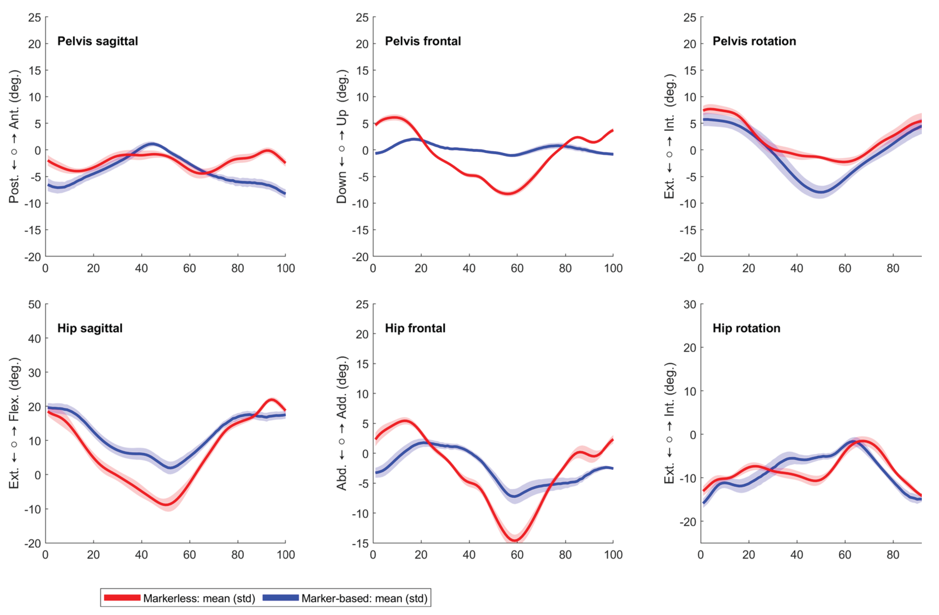
Table 1.
The RMSE between WF and RW in both systems with a RMSE comparison of markerless and marker-based systems for both WF and RW.
Table 1.
The RMSE between WF and RW in both systems with a RMSE comparison of markerless and marker-based systems for both WF and RW.
| Pelvic tilt | Pelvic obliquity | Pelvic rotation | Hip flexion | Hip adduction | Hip rotation | Knee flexion | Ankle flexion | |||
|---|---|---|---|---|---|---|---|---|---|---|
| Mean (SD) | Mean (SD) | Mean (SD) | Mean (SD) | Mean (SD) | Mean (SD) | Mean (SD) | Mean (SD) | |||
| MEAN RMSE (WF/RW) | GRAND MEAN | |||||||||
| Markerless (°) | 1.9(1.3) | 5.8 (3.2) | 1.9 (2.0) | 4.6(2.9) | 6.6 (3.9) | 3.0(2.4) | 3.6 (2.5) | 8.5 (4.6) | 4.5(2.9) | |
| Marker-based (°) | 1.1(0.9) | 0.31(0.2) | 0.8(0.6) | 1.7(1.4) | 0.6(0.5) | 1.0 (0.7) | 1.3 (1.2) | 0.8 (0.8) | 1.0 (0.8) | |
| Difference (°) | 0.8(0.4) | 5.4(3.0) | 1.1 (1.4) | 2.9 (1.5) | 6.0 (3.4) | 2.0 (1.6) | 2.3 (1.3) | 7.7 (3.8) | 3.5 (2.1) | |
| MEAN RMSE (markerless/ marker-based) | ||||||||||
| RW (°) | 6.9 (3.6) | 5.3 (3.2) | 3.8 (5.3) | 8.0 (5.1) | 6.1 (4.2) | 4.7 (4.8) | 5.8 (4.5) | 11.9(6.4) | 6.6 (4.6) | |
| WF (°) | 6.6 (3.6) | 2.8 (2.1) | 2.9 (2.0) | 8.9 (5.6) | 3.5 (2.5) | 4.0 (3.0) | 5.6 (4.2) | 4.7 (3.4) | 4.9 (3.3) | |
| Difference (°) | 0.3(0.0) | 2.5 (1.1) | 0.9 (3.3) | -0.9(-0.5) | 2.6(1.7) | 0.7 (1.8) | 0.2 (0.3) | 7.2 (3.0) | 1.7 (1.3) | |
|
MAX RMSE (markerless/ marker-based) |
||||||||||
| WR (°) | 10.9 (3.4) |
10.8 (2.3) | 10.1 (12.0) | 14.7 (5.5) | 13.1 (5.2) | 12.2 (8.0) | 13.3 (5.2) | 22.9 (7.2) | 13.5 (6.1) | |
| WF (°) | 9.6 (3.4) | 6.0 (2.2) | 6.1 (1.8) | 14.2 (5.2) | 7.6 (2.4) | 8.5 (2.8) | 10.8 (5.2) | 10.9 (4.0) | 9.2 (3.4) | |
| Difference (°) | 1.3 (0.0) | 4.8 (0.1) | 4.0 (11.2) | 0.5 (0.3) | 5.5 (2.8) | 3.7 (5.2) | 2.8 (0.0) | 12.0(3.2) | 4.3 (2.7) | |
Table 2.
Spatial-temporal and kinematic parameters for WF between marker-based and markerless system.
Table 2.
Spatial-temporal and kinematic parameters for WF between marker-based and markerless system.
| Parameter | Marker-based | Markerless | Difference | Spearman correlation | ||||
|---|---|---|---|---|---|---|---|---|
| Right | Left | Right | Left | Right | Left | Right | Left | |
| Mean (STD) |
Mean (STD) |
Mean (STD) |
Mean (STD) |
Mean (STD) |
Mean (STD) |
Corr (P-value) |
Corr (P-value) |
|
| Stride length (m) | 1.31 (0.12) | 1.31 (0.13) | 1.31 (0.12) | 1.31 (0.13) | 0.00 (0.01) | 0.00 (0.01) | 1.00 (<0.001)* | 1.00 (<0.001)* |
| Step width (m) | 0.09 (0.02) | 0.10 (0.02) | 0.10 (0.02) | 0.11 (0.03) | 0.01 (0.01) | 0.01 (0.01) | 0.94 (<0.001)* | 0.95 (<0.001)* |
| Step length (m) | 0.65 (0.06) | 0.67 (0.07) | 0.65 (0.06) | 0.66 (0.07) | 0.00 (0.01) | 0.00 (0.00) | 0.98 (<0.001)* | 0.99 (<0.001)* |
| Gait speed (m/s) | 1.24 (0.15) | 1.25 (0.15) | 1.23 (0.15) | 1.24 (0.15) | 0.00 (0.01) | 0.00 (0.01) | 1.00 (<0.001)* | 0.99 (<0.001)* |
| Pelvis tilt mean (°) | -1.1 (7.2) | -1.0 (7.0) | -1.0 (2.4) | -1.0 (2.3) | 0.1 (7.2) | 0.0 (7.1) | 0.28 (0.43) | 0.20 (0.58) |
| Pelvis obliquity mean (°) | -1.5 (2.0) | 1.4 (2.0) | 0.7 (0.7) | -0.4 (0.6) | 2.1 (2.0) | 1.9 (1.9) | 0.16 (0.66) | 0.39 (0.26) |
| Pelvis obliquity ROM (°) | 8.3 (2.8) | 8.3 (2.9) | 9.6 (2.5) | 10.1 (2.4) | 1.3 (4.7) | 1.7 (4.7) | -0.42 (0.23) | -0.43 (0.22) |
| Pelvis obliquity IC (°) | -3.1 (3.0) | -0.2 (2.7) | 1.4 (2.9) | 1.1 (2.2) | 4.4 (3.4) | 1.3 (2.7) | 0.15 (0.68) | 0.31 (0.39) |
| Pelvis rotation ROM (°) | 11.3 (3.9) | 11.4 (3.7) | 11.8 (2.7) | 11.7 (2.8) | 0.5 (4.3) | 0.3 (4.4) | 0.18 (0.63) | 0.32 (0.37) |
| Mean pelvis rotation(°) | -0.5 (1.8) | 0.6 (2.0) | -1.9 (1.7) | 2.0 (1.7) | 1.3 (2.0) | 1.4 (2.0) | 0.24 (0.51) | 0.22 (0.54) |
| Hip flexion ROM (°) | 43.4 (4.6) | 41.2 (8.8) | 46.9 (3.6) | 45.8 (6.7) | 3.5 (2.9) | 4.6 (4.9) | 0.64 (0.05)* | 0.65 (0.05)* |
| Hip flexion IC (°) | 26.5 (9.2) | 26.4 (8.0) | 26.0 (3.5) | 25.1 (3.9) | 0.4 (8.9) | 1.3 (9.4) | 0.22 (0.54) | -0.21 (0.56) |
| Hip sagittal - max extension (°) | -15.0 (8.8) | -13.9 (10.6) | -17.9 (2.8) | -18.0 (4.8) | 2.9 (9.4) | 4.1 (10.8) | -0.16 (0.66) | 0.03 (0.95) |
| Hip Abduction ROM (°) | 13.7 (3.0) | 14.6 (4.0) | 15.7 (3.0) | 16.5 (3.5) | 2.1 (4.2) | 1.9 (5.2) | 0.02 (0.97) | -0.04 (0.92) |
| Hip Abduction IC (°) | -2.8 (2.0) | -0.6 (4.0) | 2.3 (3.2) | 1.2 (2.2) | 5.1 (3.6) | 1.8 (3.8) | -0.12 (0.76) | 0.25 (0.49) |
| Hip rotation ROM (°) | 11.5 (2.8) | 11.0 (3.4) | 11.7 (2.3) | 11.4 (2.3) | 0.2 (3.2) | 0.4 (3.2) | 0.27 (0.45) | 0.37 (0.30) |
| Hip rotation IC (°) | -4.6 (4.9) | -7.8 (5.8) | -4.8 (3.5) | -5.5 (5.4) | 0.2 (2.7) | 2.3 (4.3) | 0.87 (0.00)* | 0.75 (0.02)* |
| Mean hip rotation – stand phase (°) | -2.4 (3.9) | -5.2 (5.6) | -0.1 (3.3) | -3.1 (4.6) | 2.3 (2.4) | 2.0 (4.4) | 0.67 (0.04)* | 0.54 (0.11) |
| Knee flexion ROM (°) | 58.5 (3.2) | 58.5 (4.0) | 60.3 (4.4) | 61.2 (4.2) | 1.8 (2.8) | 2.7 (3.7) | 0.55 (0.10) | 0.73 (0.02)* |
| Knee flexion IC (°) | 14.2 (4.8) | 14.3 (3.4) | 11.2 (5.1) | 11.3 (5.7) | 3.0 (3.3) | 3.0 (5.3) | 0.79 (0.01)* | 0.37 (0.30) |
| Maximal Knee extension (°) | 8.7 (2.8) | 8.7 (3.8) | 4.2 (3.6) | 2.9 (2.4) | 4.5 (3.3) | 5.8 (4.3) | 0.55 (0.10) | -0.10 (0.79) |
| Maximal knee flexion (°) | 65.2 (2.6) | 65.3 (3.4) | 63.4 (2.0) | 63.4 (3.9) | 1.8 (2.0) | 1.9 (4.3) | 0.33 (0.35) | 0.19 (0.61) |
| Ankle flexion ROM (°) | 28.7 (4.0) | 25.9 (4.4) | 29.3 (3.0) | 28.9 (5.2) | 0.6 (3.9) | 3.1 (4.7) | 0.37 (0.30) | 0.39 (0.26) |
| Ankle flexion IC (°) | 1.9 (2.6) | 4.4 (1.8) | -1.5 (3.7) | -3.0 (2.5) | 3.4 (3.3) | 7.5 (3.0) | 0.43 (0.22) | -0.10 (0.79) |
| Maximum stance dorsiflexion (°) | 15.4 (3.0) | 16.9 (3.7) | 14.8 (2.7) | 13.8 (4.4) | 0.6 (3.7) | 3.1 (3.4) | 0.20 (0.58) | 0.49 (0.15) |
| Maximum swing dorsiflexion (°) | 16.6 (3.9) | 18.4 (3.5) | 16.8 (2.4) | 16.9 (3.8) | 0.2 (3.8) | 1.5 (3.2) | 0.33 (0.35) | 0.44 (0.20) |
| Maximum plantar flexion (°) | -11.8 (5.1) | -7.4 (6.0) | -12.3 (4.0) | -11.9 (6.3) | 0.5 (3.6) | 4.5 (3.9) | 0.62 (0.06) | 0.77 (0.01)* |
| Foot progression angle (°) | 10.2 (3.1) | 10.0 (5.3) | 5.5 (3.4) | 6.1 (6.3) | 4.8 (4.1) | 3.8 (5.6) | 0.26 (0.47) | 0.16 (0.66) |
| Angle lift off (°) | 61.2 (5.3) | 60.7 (5.3) | 59.3 (7.8) | 59.5 (6.2) | 1.9 (7.0) | 1.2 (5.1) | 0.12 (0.76) | 0.73 (0.02) * |
| Angle Landing (°) | 11.9 (3.8) | 12.4 (2.3) | 6.0 (3.4) | 4.8 (3.1) | 5.9 (3.6) | 7.6 (3.4) | 0.42 (0.23) | -0.02 (0.97) |
ROM - range of motion, IC- initial contact, * p-value < 0.05, bold letters indicate p-value<0.05 on both sides.
Disclaimer/Publisher’s Note: The statements, opinions and data contained in all publications are solely those of the individual author(s) and contributor(s) and not of MDPI and/or the editor(s). MDPI and/or the editor(s) disclaim responsibility for any injury to people or property resulting from any ideas, methods, instructions or products referred to in the content. |
© 2024 by the authors. Licensee MDPI, Basel, Switzerland. This article is an open access article distributed under the terms and conditions of the Creative Commons Attribution (CC BY) license (http://creativecommons.org/licenses/by/4.0/).
Copyright: This open access article is published under a Creative Commons CC BY 4.0 license, which permit the free download, distribution, and reuse, provided that the author and preprint are cited in any reuse.


