Submitted:
02 June 2025
Posted:
03 June 2025
Read the latest preprint version here
Abstract
The study of the emission, propagation, and reflection of balls leads to the mechanical ballistic law that applies to balls with and without mass. A natural extension of the ballistic law is to encompass massless entities such as light. According to the ballistic law, a ball or a light wavefront emitted by a source inherits the velocity of its source in the absolute frame. The ballistic law governs the kinematics of balls or light in inertial frames from the background of the absolute frame. The mathematical expression of the ballistic law gives the propagation velocity of a ball or a light wavefront as the vector sum of the ball’s or the light wavefront's emitted velocity and its source's velocity. The ballistic law explains why the speed of light is a universal constant c in any inertial frame in which a source and a mirror are at rest, the laws of physics have the same form in any inertial frame, and no experiment in such a frame can prove its motion. By understanding the kinematics of light, we can understand the multiple issues rooted in Lorentz’s transformation and Einstein’s special relativity. For example, the theory of special relativity misapplies the symmetry observed in some phenomena to two inertial frames. Thus, it duplicates a physics phenomenon from one inertial frame, considered stationary, to another. The Lorentz transformation confirms the speed of light c in the traveling direction of the inertial frame and the opposite direction; simultaneously, it varies in any other direction, converging to infinity. Lorentz’s transformation has no length contractions or dilations as special relativity pretends. These conclusions prove that the theory of special relativity is self-negating. This study confirms the constancy of time passage in the universe and the variability of the propagation speed of light wavefronts in the absolute frame. Reproduced from Physics Essays, Vol. 37, Page No. 289, Year 2024, with permission from Physics Essays Publication.
Keywords:
kinematics of balls
; kinematics of light
; ballistic law
; geometrical optics
; emission of light
; propagation of light
; reflection of light
; speed of light
; observation of light
; Lorentz’s transformation
; special relativity
1. Introduction
From 2017 to 2019, we studied Michelson‒Morley's experiment, Fizeau's experiment, the observation of binary stars, and other light-related topics more profoundly than the previous approaches, but with the same understanding of physics phenomena. These studies were essential in leading us to light reflection, emission, and propagation as mechanical phenomena in the following years.
The first part of this article summarizes the kinematics of balls, with and without mass, and light, a concept emerging from a series of articles starting at the beginning of 2020. The study of ball reflection gives the velocity formula for a ball reflected by a wall for any incident angle the moving ball makes with the wall’s moving direction and for any inclination of the wall, not just the known formula for a two-ball frontal collision. A complete study of ball reflection for any incident angle and wall inclination was required when the reflection of hypothetical massless balls was applied to light as a massless entity. We continued with the emission and propagation of balls with and without mass, which, when applied to light, show that the emitted light inherits and maintains the velocity of the source at emission and afterward. Experiments and observations misunderstood for a century have been explained by the end of 2023.
The second part of this article examines the Lorentz transformation and special relativity, revealing their hidden inaccuracies.
2. Kinematics of Balls
2.1. Balls Brought from Rest to a Velocity
Figure 1 exemplifies in the absolute frame a carrier that brings a ball from rest at a point to a velocity at a point . At point the carrier stops, and the ball travels free at the velocity .
The constant force created by the carrier acts on the ball of mass in a straight line of a length at a constant acceleration . In time , while the speed of the ball increases from rest to , the inertial force of the ball acts with the same magnitude in the opposite direction of the force , which changes the ball’s state. Energy consumed to overcome is given by the mechanical work created by the force along the length , . While the ball is moved from rest to speed , it gains energy stored in its momentum , which opposes any force that changes its new state. Indeed, the integral of momentum as a linear function with a constant slope and a variable speed from zero to a value gives the energy gained by the ball, . When the force stops at , the ball continues traveling at the velocity having momentum .
Suppose a carrier with balls of different masses travels from rest to a constant velocity . At velocity , all balls travel independently from the carrier and one another with velocity , regardless of their mass. At the limit, when a ball's mass converges to zero, the hypothetical massless ball travels at the same velocity . Unlike balls with mass, the massless balls travel from rest to speed without a force to act upon them, , without energy consumption, , and without momentum after that, . Massless balls need a carrier that only consumes energy for itself.
2.2 Balls Emitted at Velocity V by a Moving Source at Velocity v
Figure 2 represents in the absolute frame a source of balls at velocity that emits at the point a ball at an instantaneous velocity in the direction . The kinematics of the emitted ball of mass depends on two vector momenta. One momentum is given by , which the ball already has while moving with the source, and another by at the emission. The vector sum of the two momenta is , where and is the ball's propagation velocity along the path in time . The action and reaction forces between the source and the emitted ball at the instant of emission are not considered.
The vector equation of momentum is independent of the balls’ mass; therefore, the vector equation of velocities is . At the limit when the ball mass converges to zero, the equation of the vector velocities has the same form, . In this case, no action and reaction forces are present between the source and the massless ball at the instant of emission.
Suppose in the absolute frame, a hypothetical source traveling at a velocity emits balls of different masses at the same speed. Thus, each emitted ball, including massless ones, respects the vector equation of momentum and the vector equation of velocities . For massless balls, the vector equation of momentum is respected as well, is zero as and are.
2.3. Ballistic Law Applied to Balls Emitted by a Source in Motion
Considering Subsections 2.1 and 2.2, we can understand the phenomenon acting on a ball emitted by a source formulated in the ballistic law: A ball emitted at a velocity by a source at the velocity travels in the absolute frame at the propagation velocity given by the vector sum of the emitted velocity and the source’s velocity , , unless a force acts on it. Velocity varies in direction and magnitude according to the direction of velocity from the direction of velocity .
Suppose a source at rest in the absolute frame emits spherical ball fronts at a speed and period uniformly distributed in space. Each spherical ball front has its center at the source at all times.
Figure 3 illustrates a circular ball front emitted in the paper plane by a source traveling at a velocity in the absolute frame. The drawing presents the case when at a scale for m/s and m/s. At the initial instance at point , the source emits a spherical ball front. After time s, the ball source is at point .
When the source is at point , the figure shows the instantaneous circle of the velocities with the center at belonging to the inertial and absolute frames. The instantaneous velocities originating at and ending on the circle with the center at the point , which belongs to the absolute frame. Both circles have a radius of m. Velocities , velocities , and velocity are shown in thick lines.
After time s, the ball front emitted at is on the circle with a radius of m with the center at the point .
Velocities apply to balls in the absolute frame. For example, the ballistic law acts on the ball emitted in the direction , and the velocity along is the vector sum of velocity along and common velocity along . The same reasoning applies to the velocity of any other ball.
The ballistic law acts in the background of the absolute frame and makes the phenomenon in the inertial frame of the source identical to that in the absolute frame. The circular ball front is emitted at the speed , with balls uniformly distributed in the inertial frame, having their center at the source at all times. In the absolute frame, the circular ball front travels at the velocity with its center at the source location at all times, expanding with a radius increasing in time with . The paths of balls in the inertial frame are shown in thin red lines, and those in the absolute frame are in thin dashed red lines.
The ballistic law governs the kinematics of balls, with mass and massless, and it can be extended to massless entities such as light. Therefore, the constant light speed of an electromagnetic nature, given by Maxwell’s equations, emitted in the absolute frame by a source in motion in any direction, replaces the emitted velocity from mechanics. The velocity of the source of a mechanical nature remains the same. Therefore, the propagation velocity of a wavefront in the absolute frame is the vector equation , which applies in the absolute frame to each wavefront emitted in any direction; velocity varies in direction and magnitude according to the direction of the emitted velocity from the direction of velocity . In the source inertial frame, the phenomenon is like in the absolute frame; each spherical wavefront has its center at the source at all times. Light travels in any direction at the speed , wavelength , period , and frequency .
2.4. Elastic Collision of Two Balls Moving in Opposite Directions
In the absolute frame, two balls, one with mass traveling at velocity and the other with mass traveling at velocity, are engaged in a frontal elastic collision, as shown in Figure 4. The velocities of the balls after collision are and, respectively. The equations for the law of conservation of momentum and energy of the balls before and after collision are as follows:
The two equations yield the solution for speed and .
For , the simplified solution and. The solutions are offered without considering the direction of the velocities. Considering the direction of positive, the direction of is negative, and the directions of and are positive, as shown in Figure 4. Therefore, the simplified solutions with approximation become and. At the limit when converges to zero, the simplified solutions are and
When the ball of mass travels in the opposite direction, the simplified solutions for the massless balls are and , for the same positive direction.
The massless balls obey the law of conservation of momentum , and the law of energy conservation . According to the equations of these two laws, massless balls do not have momentum, and no energy is required to change their state.
A wall can replace the ball of mass to study the reflection of massless balls in any direction, as in Figure 5. The mass of the wall can be ignored when studying massless balls.
Eq. (3), , is given in the frame at absolute rest, indicating that adds once to and twice. In the wall’s inertial frame, the incident speed of the massless ball relative to the wall is , where is the speed of the wall in the opposite direction of the incident velocity ; in Figure 5, . The speed of the reflected massless ball is ; velocities and are equal in magnitude and opposite directions. In the frame at absolute rest, the speed of the reflected massless balls is , where is the speed of the wall in the direction of the reflected massless ball; in Figure 5, . The expression , where , yields the following equation:
Eq. (4) offers the meaning of velocities and and provides the massless ball’s speeds reflected in the absolute frame , where is the emitted velocity of the massless ball coming from any direction relative to the wall. The wall may have inclinations other than from the velocity . In this case, the angles of the incident speed and the reflected speed measured from the velocity are different from ; therefore, the magnitudes of velocities and are different from of Figure 5.
Eq. (4) applies to the reflection of hypothetical massless balls and light by a moving wall/mirror, and with approximation to the reflection of balls with mass by a moving wall in an elastic collision when .
2.5. Elastic Reflection of a Ball by a Moving Wall
Figure 6 illustrates, in the absolute frame, a wall W traveling at a velocity and a ball traveling at a velocity hitting the wall in an elastic collision; the wall’s mass is much greater than the ball’s mass . The wall reflects the ball in an elastic collision at a point of the wall in the wall’s inertial frame and its corresponding instant point in the absolute frame. The angle of the incident ball velocity and reflected ball velocity are equal and measured from the normal to the wall at the identical points and , according to the law of reflection. One second after the collision, the ball is at point , and the wall is at point .
This section employs Eq. (4), , in which the speed of the ball replaces and the reflected speed of the ball in the absolute frame replaces :
In the instant collision in the inertial frame, the speed of the wall in the opposite direction of the incident ball is , and in the absolute frame, the speed of the wall in the direction of the reflected ball is . Another form of Eq. (5) is
where angles and are measured counterclockwise from the velocity .
In the absolute frame, the wall moved in one direction; however, the wall inclination reflects a ball in multiple directions. In the inertial frame of the wall, the velocity of the ball,, is given by the vector subtraction of velocity and , . The triangle represents the ball’s velocities at any time, and on another scale, the momentum triangle.
2.6. Emission, Propagation, and Reflection of Balls in the Absolute Frame and an Inertial Frame
Figure 7 illustrates an identical source of balls and a rigid wall at rest in the absolute and an inertial frame. The source and wall have the same geometry; each source is at the origin of its frame.
In the absolute frame , the source at the origin emits a ball at a velocity at an angle from the axis . After time , the ball is at the point on the wall . At point , the ball is reflected in an elastic collision at a velocity and then travels along the path in time . The velocities and have the same emitted magnitude . The ball travels paths and in time at speed . The ball continues to travel in the direction.
The inertial frame travels at velocity , and the source is at the origin . The origin and points and belong to the inertial frame, and their instances in the absolute frame are given a corresponding index. The source at the point emits a ball at the velocity in the direction at the angle from the axis . The ball inherits the velocity of the source, and travels on the path at the propagation velocity , given by the vector sum of the emitted velocity and source velocity . The velocity does not change its direction and magnitude along the path .
At point , the ball is at ; it has traveled in the inertial frame along the path at speed in time , and the direction makes angle from the axis . Path is path in the inertial frame, identical to in the absolute frame. If the source emits other balls between and , all balls are on the path .
In the elastic collision at point , the wall perceives only the magnitude and direction of the velocity of the emitted ball because both the ball and the wall have the same velocity . The incident and reflected angles are measured from the normal to the wall at the collision point to the incident velocity and reflected velocity as in the absolute frame. After reflection, the velocity keeps the ball moving in the same direction with the same magnitude . The ball travels on the propagation path at the propagation velocity , given by the vector sum of the reflected velocity along and source velocity . The velocity does not change its direction and magnitude along the path . At point , the ball is at , and the direction makes angle from axis . The ball has traveled the path at speed in time and the path at speed in time . Path is the path in the inertial frame, which is identical to the absolute frame. At point , the ball has traveled the paths and in time at speed , as in the absolute frame.
Newtonian mechanics formulates observations and experiments rationally understood in laws applicable to experiments, phenomena, and the needs of everyday life. However, Newtonian laws state nothing about observing these phenomena.
3. Kinematics of Light
The kinematics of light based on the ballistic law arises from a series of articles [1,2,3,4,5,6,7,8,9,10,11,12,13] regarding light emission, propagation, and reflection applied to a few fundamental experiments. The reflection of light as a mechanical phenomenon [1,2,3] was the first step. The experiment regarding the reflection and emission of light, [13] summarized in Appendix A, was the turning point in our understanding of the kinematics of light.
We used the expressions “observer in the absolute frame” and “observer in an inertial frame,” meaning that these hypothetical observers observe phenomena as they are in their frames. These expressions may be eliminated to avoid confusion with human observation and to state directly how the phenomena are, as in Newtonian mechanics. The expression “local observer” is particularly essential.
A local observer perceives the phenomena through light coming directly from a source or reflected by objects from the observer’s frame or others, as well as through partially reflected wavefronts of light by some particles of the transparent medium, such as air, through which light travels. Therefore, a local observer perceives a physical phenomenon differently from the reality of Newton's laws. Nevertheless, we may better understand reality by applying Newtonian laws and local observations of light.
Electromagnetic theory gives the universal constant speed of light emitted by a source at rest or in motion in the empty space of the absolute frame. The speed of light behaves similarly to the emitted speed of a ball, as presented in Subsections 2.5 and 2.6.
3.1. Ballistic Law Applied to Light Emitted by a Source in Motion
This study considers light propagation as a continuous phenomenon in which each wave point is a wavefront. The ballistic law of massless balls applies to light: A wavefront emitted at the velocity by a source at the velocity travels in the absolute frame at the propagation velocity , given by the vector sum of the emitted velocity and the source’s velocity , , unless a restriction arises in its propagation direction. Velocity varies in direction and magnitude according to the velocity direction from the velocity direction.
Suppose a light source at rest in the absolute frame emits waves in all directions. The spherical wavefront has its center at the source at all times, waves are uniformly distributed to the source, and waves travel at the emitted speed with wavelength , period , and frequency in any direction. The phenomenon is a sphere with the center at the source at rest, continuously expanding with a radius increasing in time with . At each point of the spherical wavefront, a local observer observes the wave coming from the source with a delay according to the time from its emission, traveling at the speed of , wavelength , period , and frequency .
Figure 8 illustrates the circular wavefront emitted in the paper plane by a light source at the origin of an inertial frame that travels at the velocity in the absolute frame. Figure 8 presents the case when to scale for m/s, m/s. At the initial instance, at the point , the source emits a spherical wavefront. After time s, the source is at point .
When the source is at the point , the figure shows the circle of the instantaneous velocities with the center at , which belongs to the inertial and absolute frame and the instantaneous propagation velocities , originated at and ending at the circle with the center at the point , which belongs to the absolute frame. Both circles have a radius of m. Velocities , , and are shown as vectors in thick lines. A specific velocity applies to each wavefront emitted in the absolute frame. The vector sum of velocity of the wavefront emitted at in the direction and the common velocity along gives propagation velocity along the path traveled in one second. With the same reasoning, each velocity can be distinguished from the multiple lines.
At point , after s from the initial instance, the circular wavefront emitted at has a radius of m. The wavefront emitted at in the direction traveled the path at speed in the absolute frame and the path at speed in the inertial frame. The traveling direction of the wavefront does not change along . A local observer at point observes the wavefront coming from , not . The traveling path of each wavefront in the absolute frame is shown in a thin dashed line, and in the inertial frame is shown in a thin continuous line.
Each emitted wavefront inherits the velocity of the source in the absolute frame, such that in the source inertial frame, waves in any direction travel at the emitted speed with wavelength , period , and frequency . The phenomenon in the inertial frame of the source is like that in the absolute frame. In the absolute frame, the phenomenon of the inertial frame travels at the velocity .
3.2. Reflection of Light by a Moving Mirror
illustrates, in the absolute frame, a mirror traveling at velocity and the source of coherent light at rest. Wavefronts, reflected at a point of the mirror, belong to waves originating from the sequential points of the source.
This section employs Eq. (4), , in which the electromagnetic speed replaces and the reflected speed of the wave in the absolute frame replaces :
In the inertial frame of the mirror, in the instant of collision, the speed of the mirror in the direction opposite to the incident light is . In the absolute frame, the speed of the mirror in the direction of the reflected light is . Another form of Eq. (7) is
where angles and are measured counterclockwise from the velocity .
In the absolute frame, the mirror moves in one direction, but the inclination of the mirror reflects light in multiple directions.
A second after the collision at , the wavefront from is at , and the mirror is at . Wavefronts reflected between and travel in the absolute frame in the direction at speed . In the inertial frame of the mirror, wavefronts travel at velocity given by the vector subtraction of the wavefronts’ velocity and the velocity of the source , . A local observer at point perceives the wavefront as coming from , not from the actual location of the mirror at .
The source may not be at rest, therefore, the speed of light propagation is in the absolute frame. In this case, the mirror may also perceive the source’s velocity, not only the emitted velocity. In References 6 and 7, we approached this general consideration.
3.3. Emission, Propagation, and Reflection of Light as Mechanical Phenomena in the Absolute Frame and an Inertial Frame
The study of the emission, propagation, and reflection of light is based on that of massless balls, as described in Subsection 2.6. The mechanical velocity is the same as that for massless balls. The emitted velocity replaces the velocity of the balls.
Figure 10 illustrates an identical light source and reflecting mirror at rest in the absolute and an inertial frame. The source and mirror have the same geometry; each source is at the origin of its frame.
In the absolute frame , the source at the origin emits a wavefront at velocity at an angle from the axis . After time , the wavefront is at point of the mirror . At point , the wavefront is reflected at velocity , then travels the path in time . The velocities and have the magnitude . The light travels paths and in time at speed , wavelength , period , and frequency .
The inertial frame travels at velocity , and the source is at its origin . Points and and origin belong to the inertial frame, and their instances in the absolute frame receive a corresponding index. The source emits a wavefront at the velocity in direction at the angle from axis . The wavefront travels on the propagation path at the propagation velocity , given by the vector sum of the emitted velocity and the source’s velocity . The velocity does not change its direction and magnitude along the path . At point , the wavefront is at ; it has traveled the path at speed in time , and the direction makes angle from axis . Path is path in the inertial frame, which is identical to in the absolute frame. The wave’s wavefronts that are emitted in the direction at point between and are on the path .
At point of the reflection, the mirror perceives only the magnitude and direction of the emitted velocity because the wavefront and mirror have the same velocity . The incident and reflected angles are measured from the normal to the mirror at the collision point to the incident velocity and reflected velocity . After reflection, the velocity keeps the wavefront moving in the same direction with the same magnitude . The wavefront travels on the propagation path at the propagation velocity , given by the vector sum of the reflected velocity in the direction and source velocity . The velocity does not change its direction and magnitude along path . At point , the wavefront emitted from is at , the direction makes angle from axis , and the wavefront has traveled the path at speed in time and the path at speed in time . Path is the path in the inertial frame, which is identical to that in the absolute frame. At point , light has traveled the path and in the time at speed , with wavelength , period , and frequency , as in the absolute frame. A local observer at point observes the light coming from the origin , and another at the point observes the light from point .
- Discussions:
The kinematics of light makes the difference between the emission and propagation of light. Maxwell’s equations give the instantaneous velocity of the emitted light, a universal constant, relative to the source in motion in the absolute frame. When the source is at rest in the absolute frame, the waves travel at the emission speed with wavelength , period , and frequency . When the source is in motion, the waves emitted in the absolute frame at the speed inherit the source velocity of mechanical nature, and according to the ballistic law, the propagation of light speed in the absolute frame is given by . In the inertial frame of the source, light travels at the speed with wavelength , period , and frequency as in the absolute frame.
In the inertial frame of a source, a mirror at rest perceives only the emitted directions of the waves, which are then reflected accordingly. The reflected waves inherit the source’s velocity such that in the source's inertial frame, the reflected waves are as in the absolute frame, having the same speed , wavelength , period , and frequency .
The ballistic law, applicable to massless balls and light, is embedded in mechanics because it is derived from mechanics. It works in the absolute frame, which is the background of any source’s inertial frame and acts on each massless ball and light wave emitted by a source in motion, creating in the source’s inertial frame a phenomenon identical to that in the absolute frame. Therefore, the kinematics of light explains and confirms the principle of relativity, according to which no experiment in an inertial frame can prove its motion. It also explains why the laws of physics have the same form in each inertial frame and why the speed of light is a constant in inertial frames when the source and reflected mirror are at rest.
It is convenient to compare the physics phenomena from inertial frames with the frame at absolute rest, which is a hypothetical inertial frame at zero speed. The phenomena in each inertial frame are similar to those in the frame at absolute rest. Therefore, each inertial frame can be considered a local frame at absolute rest for phenomena belonging to that inertial frame. The study of a physics system belonging to an inertial frame can be performed in another frame, considered a stationary frame or a local absolute frame, where the inertial frame travels at the relative velocity between the two frames.
3.4. Experiments and Observations that Support the Kinematics of Light as a Mechanical Phenomenon
The kinematics of light explains experiments and local observations that supported special relativity because of an insufficient and incorrect understanding.
3.4.1. Michelson‒Morley Experiment
Light travels through a transparent medium at a specific constant speed independent of the source speed. Michelson and Morley [14] approached their experiment considering the theory of a fixed ether. Therefore, the speed of light emitted by a source and reflected by a mirror has the same magnitude in the hypothetical ether at rest in the absolute frame, regardless of whether the source and mirror are at rest or in motion. In the ether theory, the speed of light is limited by the ether. The Michelson‒Morley experiment predicted a fringe shift that was not confirmed by the experimental results.
The kinematics of light proves that in an inertial frame where a source of light and a mirror are at rest, the speed of light is constant of electromagnetic nature. Therefore, the kinematics of light predicts a zero fringe shift in the Michelson‒Morley experiment, which agrees with the experimental results.
3.4.2. Experiment Performed at CERN, Geneva
Without rejecting Ritz’s ballistic theory [15], the emission, propagation, and reflection of light in inertial frames [4] can explain the experiment performed at CERN, Geneva, in 1964. [16] Figure 11 illustrates this phenomenon using a simple approach.
When a boson of mass is accelerated at a mechanical speed near the constant speed of light , it decays into a particle of mass and one massless photon. At speed , particle changes direction, and the photon continues moving freely at the mechanical speed . Bosons are just carriers that give photons their mechanical speed near the constant speed of light . Bosons are not sources of light and cannot give photons the speed of electromagnetic nature. This experimental result confirmed the ballistic law of light.
3.4.3. Observation of a Star in the Universe
a illustrates the observation of a star in the universe according to the kinematics of light. Suppose that a star at a point and the Earth at a point travel at velocity . At the initial instance, the star emits a wavefront of light in the direction at the emitted speed .
After a specific time, the star travels the path and the Earth travels the path , which are of equal length . The ballistic law makes the wavefront emitted in the direction propagate along . At , the local observer perceives the wavefront as coming from . Therefore, the star is observed at its actual location.
Figure 12b illustrates the observation of a star in the universe based on the hypothesis that the speed of light is independent of the source's motion. Suppose a star at a point and the Earth at the point travel at velocity . At the initial instance, the star emits a wavefront of light in the direction at the emitted speed .
After a specific time, the star travels the path and the Earth travels the path , which are of equal length . The wavefront, emitted in the direction , reaches the point , where a local observer perceives the wavefront as coming from . Therefore, the star is observed at the initial location and not at its actual location, which means that the hypothesis of the constancy of the speed of light creates irregularities that are unobserved by astronomers. These irregularities differ from those that De Sitter incorrectly predicted. [17,18]
3.4.4. Observation of a Star’s Orbit
Light emission as a mechanical phenomenon [4] has been applied to star orbit observation. [5] Figure 13 depicts an actual star’s orbit with the center at the point of radius in the plane of the paper and an imaginary circle of radius with the center at the point and with its plane parallel to and in front of the paper plane.
The distance is perpendicular to the orbit and the imaginary circle planes. The observer at rest is located at the point . The observed star orbit of radius is centered on . The view is from the back right of the observer, enabling a clear image of the actual and observed orbits.
The distances in each set of ( and (), including all other similar distances corresponding to points , and are equal.
The waves emitted by the star in motion inherit the velocity of the star corresponding to each orbital point and travel through different paths to the local observer . At point , the star emits a wavefront of light at the velocity in the direction , but this wavefront travels along the path at the propagation velocity . The direction and magnitude of the velocity do not change along the path . At point , the observer observes the wavefront originating from point traveling at speed . At point , the star emits a wavefront of light at the velocity in the direction , ; this wavefront travels along the path , , at the same propagation velocity . The direction and magnitude of the velocity do not change along the path . At point , the observer sees the wavefront coming from the point traveling at speed along path . The observer perceives a similar observation for each point in the circular orbit.
Points , and give the corresponding points , and , points which offer in this particular case the observed orbit with the center at . The local observer sees the star's orbit rotated; this orbit has a larger diameter than the actual orbit, and the observed orbital velocity is greater than that of . The observed circular orbit increases with increasing distance d. This phenomenon compensates for our vision of seeing objects smaller with increasing distance. The speed of light from any point on the observed orbit to the observer is constant . Therefore, no time irregularities exist to refute Ritz’s ballistic theory, [15] as De Sitter explained. [17,18] Observing a star’s orbit supports our understanding of the kinematics of light based on the ballistic law.
3.4.5. Miller Experiment
Studying the emission, propagation, and reflection of light in inertial frames [4] helps us to predict zero fringe shifts for any location and altitude in Earth’s inertial frame. This explains Miller’s experiments [9,10] at the Cleveland Laboratory in 1924, [19] which employed light from local sources, as well as sunlight; the fringe shift with sunlight was of the order of . The fringe shifts of 0.08 in 1921 and 0.088 in 1925, recorded by Miller using local sources at a high altitude on Mount Wilson, remain unexplained.
3.4.6. Airy Experiment
In addition to the interactions of the emission and reflection of light with matter, there are other examples, such as the velocity of light through a moving medium [8] and the refraction of light when it travels from one medium to another, both at rest, according to Snell’s law. Airy’s experiment is an example of the dragging of light by a moving medium. Observing the star γ Draconis, Airy [20] expected to adjust the inclination of the telescope after introducing a tube with water along its axis; however, this was unnecessary. Considering the dragging of light by moving water and the experimental results, we obtained the Fresnel dragging coefficient from a mechanical perspective, where is the refractive index of the medium. [11]
3.4.7. Majorana Experiment
Majorana’s experiment [21] in Earth’s inertial frame employs a fixed light source. The light travels through three stages, each consisting of one movable and one fixed mirror, and enters a Michelson interferometer with arms of unequal lengths. The movable mirrors are fixed on a rotational disk in both directions. A fringe image is observed when the disk is at rest. When the disk is rotated from maximum speed in one direction to another, a 0.71 fringe shift is observed.
Similar to the Michelson interferometer, Majorana’s experimental device offers an outstanding contribution to the physics of light, despite changes in the interpretation of the experiment over time. Majorana misunderstood the phenomenon within the device and the significance of the fringe shift observed during the experiment, explaining the fringe shift favorably for special relativity. The reflection of light as a mechanical phenomenon [1,2,3,4] applied to the Majorana experiment [21] shows that the speed of light changes after each stage, causing a fringe shift in the Michelson interferometer. Reference 12 approximates rotational mirrors as inertial frames and derives a shift of 0.27 fringes. However, the observed fringe shift of 0.71 confirms the kinematics of light, rejecting the constancy of light propagation.
3.5. Galilean Transformation
This section studies the Galilean transformation for light, as it is in mechanics, not observed.
When extended to infinity, all the inertial frames overlap. A phenomenon in an inertial frame is instantly shared with any other inertial frame. The inertial frame that shares a phenomenon is considered at relative rest or a stationary frame.
The Galilean transformation presents how the physics phenomenon of light emission from a stationary frame is instantly shared with an inertial frame. Figure 14 depicts a stationary frame in which an inertial frame travels at velocity along the axis, and the planes and are common.
The kinematics of light proves that any inertial frame can be considered a local frame at absolute rest, a frame at relative rest, or a stationary frame; we do not assume this fact.
Origins and coincide at the initial instance when the source, belonging to the origin of the stationary frame, emits a spherical wavefront of light formed by each wave’s wavefront.
After a time s, the spherical wavefront of light has the center at , and the origin of the inertial frame is at a distance from . Therefore, each path length traveled by a wave’s wavefront represents its velocity vector and in the stationary and the inertial frame, respectively. The Galilean transformation provides the coordinates of each point on the spherical wavefront along the axis in the inertial frame. Figure 14 shows the wavefronts at points , , , , , and on the circular wavefront in the plane and their coordinates along the axis of the inertial frame .
The Galilean transformation applies to the inertial frame and consists of a set of four equations applicable to each point of the spherical wavefront that can be written as follows:
Equation applies for any direction of any point on the spherical wavefront, not only for one direction of the common axes and . Indeed, in the stationary frame, for angle , is positive, which gives , and for the angle , is negative, which yields . The path has the same direction at all times. We study light propagation, as it is, in any direction of the inertial frame, not just in one direction.
The wavefront, emitted at the initial instance from towards , travels the path at speed . It is on this circular wavefront, which enlarges continuously. In the inertial frame, this wavefront travels the path at propagation speed given by the vector subtraction of velocity along and along . Angle and speed vary according to the angle . For m/s and m/s, the speed of wavefronts varies from m/s for along , to m/s along for , to m/s along for , and to m/s along for .
In Figure 14, the circular wavefront and vectors shown in a thick line are related to the Galilean transformation; those in the thin line are associated with the ballistic law.
The physics phenomenon consists of the source, the circular wavefront, and light waves like those along , , , , , and ; all belonging to the stationary frame and none to the inertial frame. A phenomenon in an inertial frame is unique in the universe; it is independent of any other inertial frame, even if it is instantly shared in each of them through coordinates. There is no transformation of a phenomenon that undergoes changes from an inertial frame considered a stationary frame to another inertial frame that may or may not affect the laws of physics; thus, the phenomenon is not duplicated. The word "transformation" may be inappropriate; a better wording may be "Galilean coordinates.”
Figure 14 and the Galilean transformation (9) apply to balls when the source emits a circular ball front, with the balls’ speed .
- Discussions
In the Galilean coordinates shown in Figure 14, the phenomenon, which includes the light source, the circular wavefront, and the light waves along , , , , , and , belongs to the stationary frame. The circular wavefront has its center at the source located at the origin of the stationary frame. Each point of the circular wavefront has coordinates related to the origin of the inertial frame, given by Equation 9.
The ballistic law was known in Einstein’s time but unaccepted because of an incomplete understanding of its applicability to light; therefore, Einstein had to work with the above case and the following one: In Figure 14, if the source belongs to the origin of the inertial frame and the ballistic law is ignored, the phenomenon that includes the light source, the circular wavefront, and the light waves as , , , , , and belongs to the inertial frame. The circular wavefront has its center at the origin of the stationary frame, , not at the source. Thus, the circular wavefront is common if the source belongs to either of the two origins. The Galilean transformation only gives coordinates of each point of the circular wavefront in the inertial frame.
Einstein considers that, if the source belongs to the origin or , the speed of light in the inertial frame is a constant , and the common circular wavefront is observed as a circular wavefront centered at the origin , such that the phenomenon is similar to that in the stationary frame. To fulfill his hypothesis, Einstein applies a mathematical transformation identical to Lorentz’s.
If the source at the origin of the inertial frame continuously emits light waves, not just a spherical wavefront, the propagation of the waves undergoes corresponding wavelength contractions or dilations of wavelength and variable velocities to maintain time constancy for each wave direction. The phenomenon is not as in the stationary frame; even if we try a mathematical transformation to make each wave travel at the speed , length , and wavelength , because , and the waves in the inertial frame are not uniformly distributed relative to the origin .
When the source belongs to the origin , the phenomenon in the inertial frame, based on observations and experiments, and what Lorentz and Einstein tried to do through a mathematical transformation, is shown in a thin line that includes waves along , , , , and . At points and , is the propagation speed of the wavefronts in the stationary frame. Figure 14 shows that the phenomenon in the inertial frame is identical to that in the stationary frame if each wave inherits the velocity of its source, which is what the ballistic law does. In the stationary frame, the spherical wavefront, centered at all times at the origin of the inertial frame, travels at the velocity and continuously expands its radius with . This simple understanding leads to the ballistic law.
Understanding Einstein's approach to the two cases above and the ballistic law, we can conclude that the mathematical transformation proposed by Lorentz and employed by Einstein cannot describe the physical phenomenon in the inertial frame and is sufficient to reject special relativity.
4. Einsteinian Theory of Special Relativity
4.1. Einstein Suggestions
In the first paragraph on the first page of his manuscript “On the electrodynamics of moving bodies,” [22] Einstein writes the following: “It is known that Maxwell’s electrodynamics—as usually understood at the present time—when applied to moving bodies, leads to asymmetries which do not appear to be inherent in the phenomena. For example, consider the reciprocal electrodynamic action of a magnet and a conductor. The observable phenomenon here depends only on the relative motion of the conductor and magnet, whereas the customary view draws a sharp distinction between the two cases in which either one or the other of these bodies is in motion. If the magnet is in motion and the conductor is at rest, there arises in the neighborhood of the magnet an electric field with a certain definite energy, producing a current at the places where parts of the conductor are situated. However, if the magnet is stationary and the conductor is in motion, no electric field is generated in the neighborhood of the magnet. In the conductor, however, assuming equality of relative motion in the two cases discussed—to electric currents of the same path and intensity as those produced by the electric forces in the former case.”
Einstein's example describes a reciprocal experimental observation of a conductor and a magnet nearby, when one is in motion/at rest and the other is at rest/in motion, but only when the magnet is moving does an electric field appear. He might suggest that the observations are sufficient to accept the reciprocity of symmetrical phenomena, even though an electromagnetic quantity, such as an electric field, does not appear when the magnet is at rest. Appendix B shows that in both cases, an electric field appears in the moving conductor, transforming it into an electric source. Thus, Maxwell's electrodynamics leads to symmetries when applied to moving bodies; every physical quantity involved in a phenomenon appears, and the phenomena can be rationally explained. Even if the reciprocal phenomena can be explained, can we apply the symmetry of phenomena to the symmetry between two inertial frames? Einstein’s example has a magnet and a conductor in proximity, and they have reciprocal electromagnetic properties. None of these characteristics applies to a stationary and inertial frame to support special relativity. Origins of the two frames depart from each other and remain nearby for a relatively short time. The frames, including the absolute frame, are hypothetical entities. These tools help us study and understand physics phenomena. They have no properties to transform or duplicate a physical phenomenon from one frame to another.
By applying symmetry to two inertial frames, the central idea in special relativity, Einstein unrealistically creates duplicates that lead to irrational conclusions, which are discussed below.
From “Examples of this sort, together with the unsuccessful attempts to discover any motion of the earth relatively to the 'light medium',” Einstein concludes with three suggestions in the second paragraph of the first page:
- “… the phenomena of electrodynamics as well as of mechanics possess no properties corresponding to the idea of absolute rest.”
Einstein rejected the idea of absolute rest. However, the inertial frame considered stationary is a local frame at absolute rest for another inertial frame. The stationary frame was a convenient choice to present his understanding of the transformation of phenomena between the two inertial frames of reference.
- 2.
- “… the same laws of electrodynamics and optics will be valid for all frames of reference for which the equations of mechanics hold good.”
The equations/laws of mechanics are valid for phenomena belonging to an inertial frame, but not for the coordinates of phenomena in another inertial frame. However, contrary to the second suggestion, special relativity forces the laws of electrodynamics and optics to hold good for coordinate observations, for which mechanics does not.
- 3.
- “… light is always propagated in a vacuum with a definite velocity , which is independent of the state of motion of the emitting body.”
In a stationary frame/local frame at absolute rest, the emitted wavefront from a source at rest travels at the velocity in all directions. The spherical wavefront has its center continuously at the source at rest. However, without considering the ballistic law of light, a spherical wavefront emitted by a source in motion travels in a stationary frame having its center at the source emission location, not at the actual source location; see Discussions in Subsection 3.5. Therefore, there are differences in wave propagation regarding speed and wavelength if the source belongs to the stationary or inertial frame.
Without understanding the physics phenomena of his example and the comments from the above suggestions, Einstein chose to formulate hypotheses based on observations, elevating them to postulates.
4.2. Einstein's Postulates
From the three suggestions, Einstein formulates two postulates:
- “The laws by which the states of physics systems undergo change are not affected, whether these changes of state be referred to the one or the other of two systems of co-ordinates in uniform translatory motion.”
- “Any ray of light moves in the “stationary” system of co-ordinates with the determined velocity whether the ray be emitted by a stationary or by a moving body.”
A phenomenon in a stationary frame is independent of the inertial frame, even if instantly shared with the latter through its coordinates. Unlike mechanics, the first postulate forces the shared coordinates in the inertial frame to obey the same laws of physics as those applied in the stationary frame, thereby creating a fictive duplication of a phenomenon from a stationary frame into an inertial frame. The first postulate includes the phenomena of electrodynamics, optics, and mechanics in physics systems; see also Suggestion 2 of Subsection 4.1. However, in practice, special relativity is incorrectly applied to light observation.
The second postulate indicates that Einstein's study does not consider the comments regarding Suggestion 3 of Subsection 4.1.
Einstein applied this transformation when the source belonged to a stationary or inertial frame. For a clear presentation, we consider the light source to belong to a stationary frame. If the source belongs to the inertial frame, then this frame is considered stationary. Einstein presented a transformation identical to the well-known Lorentz transformation. [23]
4.3. The Lorentz Transformation and Einstein Transformation
Figure 15 depicts a stationary frame in which an inertial frame travels at a velocity along the axis, and the planes and are common. Origins and coincide at the initial instance when a light source belonging to the origin emits a spherical wavefront. After a time s, the spherical wavefront expands with a radius of magnitude , and the origin is at a distance from .
In the theory of the ether at rest in the absolute frame, the speed of light is constant . Observations and Michelson‒Morley’s experiment can be explained if the speed of light is constant to inertial frames in which the source and mirrors are at rest. With no explanation of the Michelson‒Morley experiment during his time, FitzGerald [24] wrote the following: “I would suggest that almost the only hypothesis that can reconcile this opposition is that the length of material bodies changes, according to their movement through the ether or across it, by an amount depending on the square of the ratio of their velocity to that of light.” Considering the Galilean transformation as in Section 3.5, we can understand the inaccuracy of FitzGerald’s statement by isolating a moving body event in one direction and ignoring all other directions; this is not a comprehensive study that can prove the constancy of light speed in an inertial frame.
We approach Lorentz’s transformation for wavefronts emitted in all directions by a point source of light, similarly to the Galilean transformation. The projection of each coordinate of the spherical wavefront is given in the inertial frame along the axis as the length measured from to coordinate . Therefore, Lorentz’s transformation consists of four equations that apply to each point of the spherical wavefront as follows:
where is the Lorentz factor, which is comparable to the square of the velocity and ratio, as suggested by FitzGerald. With the same reasoning as for the Galilean transformation, the equations and apply to each wavefront in the inertial frame.
Substituting at point , is the absolute length in the inertial frame, and is the hypothetical contracted time by given by Lorentz, in which the wavefront travels the length at speed . , , and then , which verifies the constancy of light. Because for , the length is longer than , and point shifts to .
Substituting at point , is the absolute length in the inertial frame, and is the hypothetical dilated time by given by Lorentz, in which the wavefront travels the length at speed . , , and then , which verifies the constancy of light. Because for , the length is longer than , and point shifts to .
For angle , is given by the length , , which gives and identical to , , and . However, the speed along , in the stationary frame, has a definite magnitude, . For angle , is given by the length and by the length , , and ; thus, shifts to the left from and the speed along is . Lorentz’s transformation, intentionally or not, duplicates the phenomenon from the stationary to the inertial frame. Here, the duplication is visually different from that in the stationary frame. It is approximately an ellipsoid shape in the inertial frame, which includes points , , identical to , to the left of , , and . Therefore, the law of physics applied in the inertial frame differs from that of the stationary frame, contradicting the first postulate of special relativity. Thus, the factor γ can be ignored; it does not support special relativity.
4.4. Simplified Lorentz’s Transformation
In Figure 15, the mechanical equation for the wavefront traveling the path is ⇒ ⇒ ⇒ with . In Lorentz’s transformation, the equation is identical to that in mechanics ; thus, lengths have an equal absolute value in both frames. If we hypothesize the constancy of light speed in the inertial frame, then the speed , from mechanics, becomes the speed and , in the inertial frame. Therefore, offers ⇒ , which is the equation of time in Lorentz’s transformation without the factor γ. We obtained the following set of equations:
Multiplying and by the factor , we obtain the Lorentz transformation. (10)
In the relativistic time of Lorentz’s transformation, the speed of light in the inertial frame in the two directions of the axis is the constant , and has the same absolute magnitude as in mechanics. Thus, the time contracts or dilates accordingly, such that to have the same magnitude as in mechanics for each spherical point; therefore, there are no length contractions or dilations.
The following numerical calculation employs lengths shown in Figure 15, which are of absolute values, including the lengths offered by Lorentz’s transformation. The length . The projection of the length along the path is , then , , . Employing relativistic speed along , ⇒ . In the inertial frame from the geometry of the triangle with absolute side lengths, the time in which the wavefront travels along at speed must be equal to the relativistic time in which the projection of the wavefront along travels at the speed . Therefore, the wavefront travels the length at speed . The same reasoning applies to the triangle and any other similar triangle.
Table 1 offers the numerical calculations for the and functions of angle at time s, identical to any other circular wavefront with its diameter along the axis .
In Table 1, we calculated the speed converging to infinity along the direction of the length for angle as the data for the angle shows. For , the speed , respectively. This result contradicts that at the end of Subsection 4.3, where the speed along the direction of has a finite value of .
Table 1 confirms that Lorentz's transformation maintains the constancy of the speed of light for the waves in the direction and the opposite direction. However, the speed in any other wave direction varies, converging to infinity. The second postulate asserts the constancy of the speed of light in the inertial frame regardless of its direction, whereas the transformation drastically concludes otherwise. The numerical calculation for Lorentz’s transformation (10) yields the same conclusion.
4.5. Lorentz’s Transformation Derived from a Mechanical Perspective
Figure 16a–c present a point source of light belonging to the origin of a stationary frame or inertial frame , which emits a wave in one direction and another in the opposite direction, as shown. The drawings are to scale for the inertial frame velocity m/s and the speed of light m/s. After a time s, the wavefront in the direction is at point , and that in the opposite direction is at point . Both points belong to the stationary frame.
Figure 16a approaches the case when the light source belongs to the origin of the stationary frame and emits in its frame waves at the speed , with wavelength , period , and frequency that are not affected by the inertial frame through which they propagate. Figure 16a gives the absolute lengths in terms of the number of wavelengths in the Lorentz transformation, as can be seen in the inertial frame of the figure and confirmed below. When the wavefront that travels along the axis arrives at the point in time , the length is given by the equation:
Eq. (12) can be written as which yields the same equation in another form
with variable speed according to the speed of the inertial frame.
Introducing Eq. (13) in Eq. (12), Eq. (12) can be rewritten as that divided by period yields where , , and are the number of wavelengths comprised in the lengths of traveled at the velocity , traveled at the velocity , and traveled at the velocity , correspondingly. For , we obtain a fractional relation of a rational number :
In Relation (14), the number of wavelengths , replaced with one , gives , or with the length , yields , or with the speed , offers . As fractional relations, all these arrangements are correct and meaningful in mechanics.
When we replace with the time , the time fractional relation
is susceptible to relativistic time interpretation.
The fractional term from relation (15) yields which is the identical equation for time in Lorentz’s transformation. We understand the meaning of the time obtained here and in the Lorentz and simplified Lorentz transformations. At point , as in mechanics and as in special relativity. The time is shorter than the time ; therefore, time in the inertial frame passes faster than that in the stationary frame to compensate for the increase in wave speed from to such as has the same length in both frames, . With similar reasoning at the point , time is longer than the time ; therefore, time in the inertial frame passes more slowly than that in the stationary frame to compensate for the decrease in wave speed from to , such as has the same length in both frames, . The wave along is not a continuous wave. Note also that the Lorentz transformation mixes the absolute term for length with the fractional term for time .
The constant speed in the inertial frame requires the fractional times to keep the same magnitude of the length in both frames. With this requirement, the Lorentz transformation offers no length contractions in the inertial frame, only dilatations when employing the factor . Even if the speed and passing of time in the inertial frame differ in special relativity from mechanics, the simplified Lorentz transformation gives the Galilean coordinates. The spherical wavefront is centered at the origin of the stationary frame, not at of the inertial frame.
With the above conclusions, the special relativity is not sustainable.
In Figure 16b, the source belongs to the inertial frame when the ballistic law is ignored. In this hypothetical case, there are wave contractions and dilatations, not those of absolute length in special relativity. However, the absolute lengths are given by the number of wavelengths with their particular wavelength. These contractions and dilatations have nothing to do with special relativity or reality. Nevertheless, this example points to the ballistic law.
Figure 16c is according to the ballistic law. The phenomenon in Figure 16a is symmetrical to the axis of the stationary frame. In Figure 16c, if the inertial frame is considered stationary, the phenomenon is symmetrical to the axis and the other frame moves in the opposite direction.
After we understand the phenomenon as it is, like in Newtonian mechanics, we can rationally study its observation. Unfortunately, special relativity addresses none of them.
4.6. Doppler Observation
Figures 17a–b illustrate a source at rest at the origin of a stationary frame that emits a wave in the direction at the speed , with wavelength , period , and frequency , which are not affected by the inertial frame through which waves propagate.
In Figure 17a, an inertial frame is moving away from the source, and in Figure 17b, it is moving towards the source, with the same speed , but in opposite directions. In the initial instance of each Figure, the origin of the inertial frame is at point . After time s, is at point , and the wavefront from is at point . Figures are drawn to scale for the speed m/s and the speed of light m/s.
In Figure 17a, the wavefront from travels in time the path at velocity in the stationary frame and the path at velocity in the inertial frame, as it is in mechanics. The number of wavelengths in the paths and is different, but the wavelength is the same. In the inertial frame, the period and frequency , which is the Doppler’s frequency observed by an observer at the origin . The physics phenomenon in Figure 17a is identical to that in Figure 16a for the wavefront in the direction .
In Figure 17b, the wavefront from travels in time the path at velocity in the stationary frame and the path at velocity in the inertial frame, as it is in mechanics. In the inertial frame, the period and frequency , which is the Doppler’s frequency observed by an observer at the origin .
The word “observation” is adequate for Doppler observation because it occurs instantly at the location of the wave observation, not at a remote point, and the wavefront from the source comes directly to the observers’ eyes. The observer at cannot perceive the waves emitted in any other direction by the source.
4.7. Discussions
Is it rational to present the observation of light without understanding its observation or a theory to explain experiments without understanding physics phenomena, or to use the laws of physics applicable in a stationary frame to Galilean coordinates in an inertial frame? Einstein chose this approach, leading to an irrational world. Unlike special relativity, Newtonian laws present phenomena as they are, rationally understood by themselves, and not accepted by observations, hypotheses, or postulates.
What natural phenomena can transform each wave from a stationary frame into its unique form, as required by Lorentz’s transformation and as shown in Figure 15? Other mathematical transformations can be considered, e.g., ignoring the Lorentz factor discussed in Subsection 4.3, or, considering the speed of light to be constant along each wave in the inertial frame, or having the time a constant and the speed of light variable according to its direction. [25] Could there be a phenomenon for each of these hypothetical mathematical transformations to explain the Michelson‒Morley experiment? If so, which one would be correct? If we try these transformations, we obtain theories with irrational conclusions similar to special relativity.
A ruler identical to that in the stationary frame is required to measure the lengths involved in phenomena that belong to the inertial frame. We also must have two rulers with different scales required by Lorentz's transformation to measure the lengths along according to positive or negative, without considering all other directions. The use of multiple rulers is unacceptable. The same conclusion applies to multiple synchronized clocks.
Suppose that the inertial frame also has a source at its origin. When the origins coincide, each source emits a circular wavefront of light. Considering factor , imagine the confusion in the inertial frames when observing two wavefronts, one of its own and another observed from the stationary frame of an ellipsoid shape.
When we observe a star that involves astronomical distances, as seen in the example of Subsection 3.4.4, we observe it in an enlarged orbit without irregularities; however, our observation does not change the actual orbit. Not to mention other observations close to our eyes that we know are not factual; these observations can be explained by the laws of physics and their perception by our eyes. However, we must distinguish between actual phenomena and their local observation. Therefore, we cannot rely solely on observations. Special relativity focuses on remote observations and makes no distinction between the emitted and propagated velocities of light. It fails to consider that our eyes perceive only the direction of waves emitted by a source and reflected by a mirror, not the direction of wave propagation.
Figure 15 illustrates a case where the origins and coincide at the initial instance. However, the origin may be far away from when the source emits a spherical wavefront at an initial instance. In this case, there is an interval of time when the circular wavefront does not include the origin , a time when the circular wavefront is at the origin , and an interval of time converging to infinity when the circular wavefront includes the origin . How is the circular wavefront observed at at these different times? Do we force the coordinates of the circular wavefront to be observed according to the Lorentz transformation, with its center at at any time? Or, can we apply the same law to all three cases?
Suppose that a source of balls in the stationary frame emits balls of equal mass uniformly distributed relative to the source at a speed that is higher than the speed of the inertial frame . As for light, the coordinates of the spherical ball front in the inertial frame at a time are as in Figure 15. Mechanics does not and cannot force the coordinates of the circular ball front to have its center at ; in Einstein’s words, “the equations of mechanics do not hold good” in this case. However, special relativity does not respect Suggestion 2 of Subsection 4.1.
The physics system mentioned in the first postulate has a source and light rays that create a circular wavefront. However, other systems may contain bodies and living beings involved in a phenomenon. Considering that the origin of inertial frames is relative, their origins can be at the origin of the stationary frame when the source emits a spherical wavefront of light. We can imagine what the physics systems’ duplication from a stationary frame in all other inertial frames means. Moreover, each inertial frame may be arbitrarily stationary; therefore, a phenomenon from an inertial frame can be duplicated in all other inertial frames. Do all these duplications occur just by choosing an arbitrary stationary frame? All these duplications are irrational and are not observed in the universe or locally.
In a stationary frame, as shown in Figure 15, the origin of the inertial frame may travel through a few consecutive points along the axis. Suppose a phenomenon arises in the stationary frame when the origin coincides with each point. Each of these phenomena is transformed at the origin . Imagine all of these phenomena involving bodies and living beings at .
5. Conclusions
Lorentz's transformation duplicates physics phenomena from a stationary frame into an inertial frame.
The transformation provides the constant speed of light in the moving and opposite directions of the inertial frame. Simultaneously, the speed varies in any other direction, converging to infinity. However, special relativity claims that the speed of light is constant in all directions.
Lorentz's transformation has no length contractions and dilatations to support this fundamental concept of special relativity. The time contraction in the moving direction of the inertial frame differs from the time dilation in the opposite direction, requiring a ruler and time synchronization in both directions and any others.
Einstein employed Lorentz’s transformation intending to obtain the constancy of light speed in inertial frames, which the ballistic law does. The mathematical Lorentz transformation without the support of a physics phenomenon cannot deliver Lorentz’s and Einstein’s intent. Nevertheless, Einstein obtained Lorentz’s transformation in his special relativity. With unintended irrational conclusions, the special relativity is self-negating.
The saga of special relativity started with FitzGerald’s statement that the length of material bodies changes based on a misunderstanding of the Michelson‒Morley experiment. Lorentz continued this with his transformation, and Einstein did so with an entire theory accepted by many others when there was no theory to explain experiments. Special relativity should not have been written or accepted.
The ballistic law is based on a physical phenomenon. The following ballistic law governs the kinematics of balls and electromagnetic radiation: A ball or light wavefront emitted by a source inherits the velocity of the source in the absolute frame. The mathematical expression of the ballistic law gives the propagation velocity of balls and light wavefronts as the vector sum of the emitted velocity of balls or wavefronts and the velocity of the source. It is reasonable, understandable without explanations, and fundamental in mechanics, like the Newtonian laws.
Matter creates the light. As a mechanical phenomenon, the kinematics of light naturally presents light in its interactions with matter at emission, reflection, refraction, and when traveling through a moving medium. Light and any other electromagnetic radiation can be considered massless matter or fields, and the kinematics of light can be included in mechanics.
The kinematics of light explains why the speed of light is a constant in any inertial frame in which a light source and reflective mirror are at rest, the laws of physics have the same form in each inertial frame, and no light experiment in an inertial frame can prove its motion.
Mechanics presents phenomena as they are. Special relativity focuses on observing phenomena rather than understanding them. Unlike these two approaches, this article presents phenomena as they are in mechanics and are perceived by a local observer, which helps us understand reality.
The kinematics of light presents the essential concept of how the human eye reacts to propagated and emitted light. The understanding that the human eye perceives only the emitted velocity by a source and not its propagation is essential in understanding physical phenomena. Based on the ballistic law, the observation of a star’s orbit is as in Subsection 3.4.4 and Reference 5. The observation perceives only the emitted velocity , offering an enlarged orbit with no irregularities. Light travels in its propagation direction, which may differ from the emitted direction. To have a good view, the human eyes must adjust in the direction of the emitted light velocity .
The inaccuracies in Lorentz’s transformation and Einstein’s special relativity not only refute them but also support the constancy of time passage in the universe and the variability of light speed in the form of wavefront propagation in the absolute frame.
Acknowledgment
I am grateful to the person who set me on the right path and inspired me to study the emission, propagation, and reflection of light as mechanical phenomena.
Appendix A: Experiment on the Reflection and Emission of Light
Michelson derived the fringe shift in his interferometer by employing the ether theory. The Michelson‒Morley experiment [14] was expected to yield a fringe shift. The experimental result was considered a failure. By employing the ether theory, we derived in References 1 and 2 the fringe shift for the particular geometry of the Michelson‒Morley experiment in which the beam splitter has an angle of from the source rays, one opaque mirror is perpendicular to the source rays, and the other is parallel to them. In this case, the expected fringe shift is also .
References 1 and 2 present the reflection of light as a mechanical phenomenon and derive the speed of light reflected by a moving mirror for any angle of the incident light from the velocity of the mirror as well as for any inclination of the mirror. The light source is at rest in the inertial frame of the mirror. The speed of light is considered independent of the light source, as in the ether theory. In this setting, the particular geometry predicts a zero fringe shift, and the geometry of the Michelson‒Morley experiment predicts a fringe shift of . These theoretical results are consistent with the experimental results. To confirm or reject this conclusion, we searched for another interferometer.
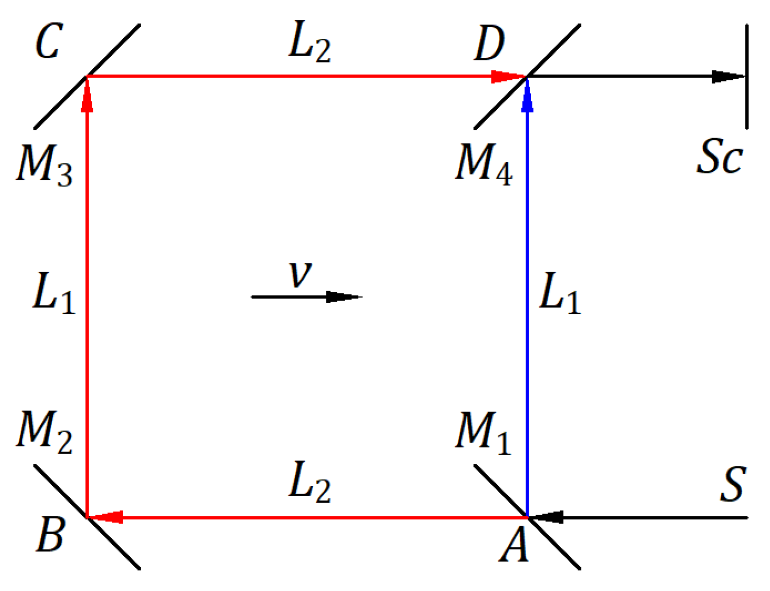
Figure A1 illustrates the interferometer at rest in an inertial frame at velocity . [13] The beam splitter splits the light from the source. The transmitted rays travel from to opaque mirrors and , beam splitter , and screen . The reflected rays travel from to the beam splitter and then to screen . All four mirrors have a 45° angle with the incoming rays. Considering the light reflection as a mechanical phenomenon, the theoretical fringe shift is derived in steps of is . [13] This predicted high fringe shift leaves no uncertainty regarding the experimental result of a zero fringe shift. Therefore, the hypotheses that light reflection is a mechanical phenomenon and that the speed of light is independent of the source speed are incompatible. If we only apply the ether theory to this interferometer, the theoretical fringe shift is zero according to the experimental results.
Figure A1.
Schematic of the interferometer.
The ether theory and the combination of the two hypotheses, that light reflection is a mechanical phenomenon and light speed is independent of the light source, lead to theoretical results inconsistent with the experimental results; therefore, we have to reject these two options. This conclusion led us to consider the reflection and emission of light as a mechanical phenomenon [4] that explains the Michelson‒Morley experiment and others presented in this article.
Appendix B: Reciprocal Electrodynamic Action of a Magnet and Conductor
In the magnetic field of a fixed magnet, Lorentz’s electromagnetic force is given by the vector product where is the velocity of a positive or negative electrical charge relative to the fixed magnetic field . When the electrical charge is at rest, and the magnet is in motion at the velocity , the velocity of the charge at rest relative to the moving magnetic field is . Considering the velocity of the electrical charge in motion relative to the fixed magnetic field or relative to the moving magnetic field when the electrical charge is at rest, Lorentz’s electromagnetic force remains the same .
The expression has units of , which in physics quantities is that represents the total electrical charge in a conductor of length through which a constant current flows. Therefore, when the magnet is fixed, the Lorentz force becomes where is the current vector in the direction of positive charge flow. Lorentz’s electromagnetic force is when the magnet is in motion and the conductor is fixed.
Lorentz’s right-hand rule and Fleming’s right-hand and left-hand rules are replaced with the following rule derived from the vector product of for perpendicular vectors. The movable quantity rotated in the short direction over the fixed quantity yields the direction of Lorentz’s force.
Figure A2a shows a magnet with a magnetic field perpendicular from the front to the back of the paper plane, and a conductor in the paper plane that can be connected to an electric current source. The magnet and conductor are in a state of equilibrium when they are at rest relative to each other, and no current flows through the conductor.
Suppose the magnet is fixed and the conductor has a degree of freedom in the paper plane in both directions perpendicular to the conductor. Connecting the conductor to the source, the source's electric field forces current to flow through the conductor from the top to the bottom of the paper. The interaction between the magnetic field and current produces an electromagnetic force of reciprocal repulsion between the conductor and magnet. The Lorentz electromagnetic force is . In this case, of the movable conductor rotated in the short direction over of the fixed magnet gives the direction of the reciprocal repulsive electromagnetic force , which moves the conductor to the right. The inertial force of the conductor acts in the opposite direction to . When the conductor is disconnected from the source, the system enters a state of equilibrium.
Suppose the conductor is fixed and the magnet has a degree of freedom in the paper plane in both directions perpendicular to the conductor. Connecting the conductor to the source, the source electric field forces the current to flow through the conductor from top to bottom. The interaction between the magnetic field and current produces an electromagnetic force of reciprocal repulsion between the conductor and magnet. The Lorentz electromagnetic force is . In this case, of the movable magnet rotated in the short direction over of the fixed conductor yields the direction of the reciprocal repulsive electromagnetic force , which moves the magnet to the left. The inertial force of the magnet acts in the opposite direction to . When the conductor is disconnected from the source, the system enters a state of equilibrium. The motion of the movable magnet may not be visible because its mass is much greater than that of the conductor.
Figure A2.
(a) A charged conductor in a magnet’s magnetic field. (b) Moving a conductor or magnet when they are in proximity.
Figure A2.
(a) A charged conductor in a magnet’s magnetic field. (b) Moving a conductor or magnet when they are in proximity.
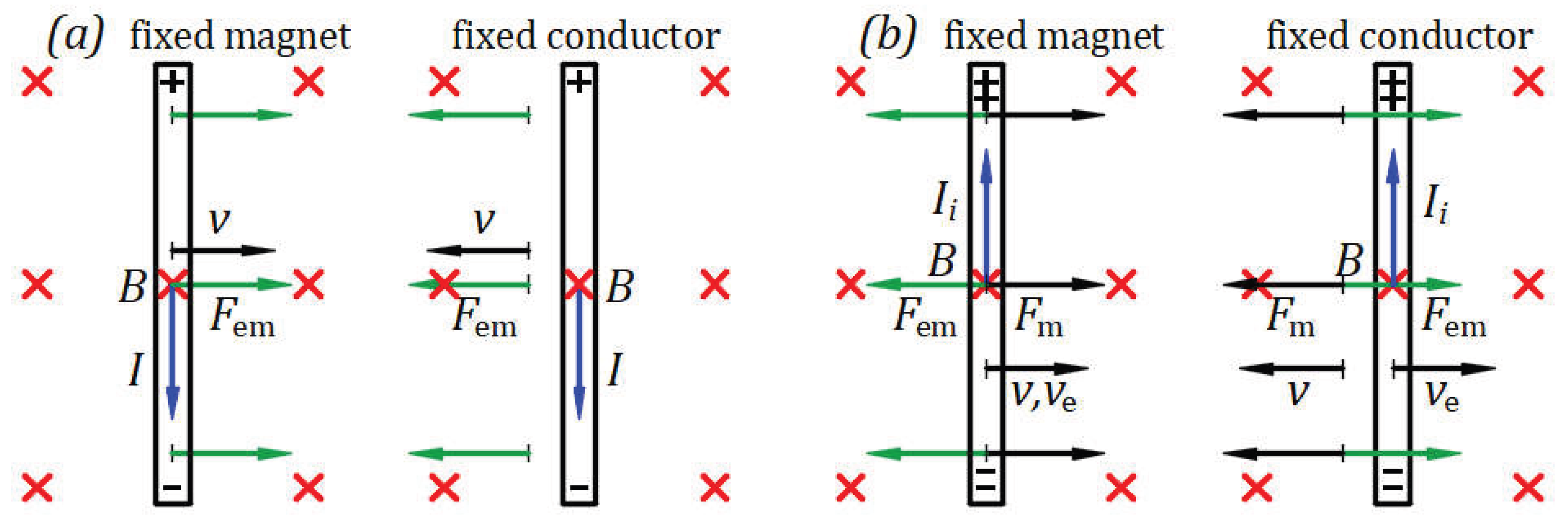
Figure A2b illustrates Einstein’s example. At rest or in motion, a magnet does not create an electric field without a conductor. The magnet and conductor must be in proximity, and one must be in motion. Einstein understood that an electric field is generated in a fixed conductor in the neighborhood of a moving magnet. Here, we explain that an electric field also arises in a moving conductor near a fixed magnet.
Suppose the magnet is fixed and the conductor has a degree of freedom in the paper plane in both directions perpendicular to the conductor. The conductor connected to a galvanometer is forced to move to the right by a mechanical force at velocity , which is the velocity of electrons from within the conductor. Lorentz’s electromagnetic force is . The fixed magnetic field acts on the moving electrons within the conductor at the velocity . The direction of electrons moving to the bottom end of the conductor can be obtained by applying the Lorentz right-hand rule. For this time, we employ the general rule. The velocity of quantity rotated in the short direction over of the fixed magnet gives the moving direction of a positive charge toward the top end of the conductor. The electrons, as negative charges, are moved to the bottom end of the conductor, and the top end becomes positively charged, creating an electromotive force (emf) within the conductor. The conductor acts as a source, and the induced electric field from the positive to the negative end within the conductor creates an induced current that flows through the galvanometer from the top positive end to the bottom negative end of the conductor.
The interaction of the magnetic field and current produces an electromagnetic force . In this case, of the movable conductor rotated in the short direction over of the fixed magnet yields the direction of the electromagnetic force of reciprocal attraction that opposes . As long as moves the conductor at the velocity , the induced current flows through the galvanometer. When the mechanical force ceases, the system reaches a state of equilibrium with the conductor at rest.
Suppose the conductor connected to the galvanometer is fixed, and the magnet has a degree of freedom in the paper plane in both directions perpendicular to the conductor. The magnet is forced to move to the left by mechanical force at velocity . Because the relative velocity of fixed electrons at rest within the conductor relative to the movable magnetic field is velocity , Lorentz’s electromagnetic force has the same form . Therefore, the induction phenomenon is similar to the previous one when the magnet is fixed and the conductor is forced to move. The magnetic field at relative rest acts on electrons within the conductor at the relative velocity . The relative velocity of quantity rotated in the short direction over of the relative fixed magnet gives the moving direction of a positive charge toward the top end of the conductor. The electrons, as negative charges, are moved to the bottom end of the conductor, and the top end becomes positively charged, creating an electromotive force (emf) within the conductor. The conductor acts as a source, and the induced electric field from the positive to the negative end within the conductor creates an induced current that flows through the galvanometer from the top positive end to the bottom negative end of the conductor.
The interaction of the magnetic field with the current produces an electromagnetic force . In this case, of the movable magnet rotated in the short direction over of the fixed conductor provides the direction of the electromagnetic force of reciprocal attraction which opposes . As long as moves the magnet at the velocity , the induced current flows through the galvanometer. When the mechanical force stops, the system enters a state of equilibrium with the magnet at rest.
References
- Filipescu F., D. Reflection of Light as a Mechanical Phenomenon Applied to a Particular Michelson Interferometer. Preprints 2020, 2020090032. [Google Scholar] [CrossRef]
- Filipescu F., D. Opposing hypotheses of the reflection of light applied to the Michelson interferometer with a particular geometry. Phys. Essays 2021, 34, 3, 268–273. [Google Scholar] [CrossRef]
- Filipescu F., D. Opposing hypotheses of the reflection of light applied to the Michelson interferometer. Phys. Essays 2021, 34, 3, 389–396. [Google Scholar] [CrossRef]
- Filipescu F., D. Emission, propagation, and reflection of light as mechanical phenomena in inertial frames. Phys. Essays 2021, 34, 4, 587–590. [Google Scholar] [CrossRef]
- Filipescu F., D. Observation of a star orbit based on the emission and propagation of light as mechanical phenomena. Phys. Essays 2022, 35, 2, 111. [Google Scholar]
- Filipescu F., D. Emission, propagation, and reflection of light as mechanical phenomena. Preprints 2022, 2022040061. [Google Scholar] [CrossRef]
- Filipescu F., D. Emission, propagation, and reflection of light as mechanical phenomena: General considerations. Phys. Essays 2022, 35, 3, 266–269. [Google Scholar] [CrossRef]
- Filipescu, F.D. Velocity of light through a moving medium applied to the Fizeau experiment. Phys. Essays 2023, 36, 1, 90–93. [Google Scholar] [CrossRef]
- Filipescu F., D. Reflection of light as a mechanical phenomenon applied to the Michelson interferometer with sunlight as a source. Preprints 2022, 2022080472. [Google Scholar] [CrossRef]
- Filipescu F., D. Reflection of light as a mechanical phenomenon applied to the Michelson interferometer with sunlight as a source. Phys. Essays 2023, 36, 2, 223–229. [Google Scholar] [CrossRef]
- Filipescu F., D. Airy’s experiment and the dragging of light by a moving medium. Phys. Essays 2023, 36, 3, 274–276. [Google Scholar] [CrossRef]
- Filipescu F., D. Emission, propagation, and reflection of light as mechanical phenomena applied to the Majorana experiment. Phys. Essays 2023, 36, 4, 361–368. [Google Scholar] [CrossRef]
- Filipescu F., D. Experiment on the reflection and emission of light. Phys. Essays 2024, 37, 1, 64–70. [Google Scholar] [CrossRef]
- Michelson A. A., Morley E. W. On the relative motion of the earth and the luminiferous ether. Am. J. Sci. 1887, s-3-34(203), 333–345.
- Ritz, W. Recherches critiques sur l’Électrodynamique Générale. Ann. Chim. Phys. 1908, 8, 145, English translation: http://www.shadetreephysics.com/crit/1908a.htm. [Google Scholar]
- Alvager T., Farley F. J. M., Kjellman J., and Wallin L. Test of the second postulate of special relativity in the GeV region. Phys. Lett. A. 1964 12, 260–262.
- De Sitter, W. A proof of the constancy of the velocity of light. Proc. R. Neth. Acad. Arts and Sci. 1913, 15(II), 1297–1298. [Google Scholar]
- De Sitter, W. On the constancy of the velocity of light. Proc. R.Neth. Acad. Arts and Sci. 1913, 16, 395–396. [Google Scholar]
- Miller D., C. Ether-Drift Experiments at Mount Wilson. Proc. Natl. Acad. Sci. U. S. A. 1925 11, 306–314.
- G. B. Airy. On a supposed alteration in the amount of Astronomical Aberration of Light, produced by the passage of the Light through a considerable thickness of Refracting Medium. Proc. R. Soc. Lond. 1871, 20, 35.
- Majorana, Q. On The Second Postulate of the Theory of Relativity: An Experimental Demonstration of the Constancy of the Velocity of Light Reflected by a Moving Mirror. Phys. Rev. 1918, 11, 411. [Google Scholar] [CrossRef]
- Einstein, A. Zur Elektrodynamik bewegter Körper. AdP 1905 322 (10): 891921. English translation: https://www.fourmilab.ch/etexts/einstein/specrel/specrel.pdf.
- Lorentz H., A. The Relative Motion of the Earth and the Aether. Zittingsverlag Akad. V. Wet. 1892 (1), 74. https://en.wikisource.org/wiki/Translation:The_Relative_Motion_of_the_Earth_and_the_Aether.
- FitzGerald G., F. Letters to the editor. 1889. https://www.science.org/doi/10.1126/science.ns-13.328.390.a.
- N. Bărbulescu, Physics foundations of Einsteinian relativity (St. & Enc. ed. Bucharest, Romania 1975), pp. 66-77.
Figure 1.
Balls brought from rest to a velocity v.
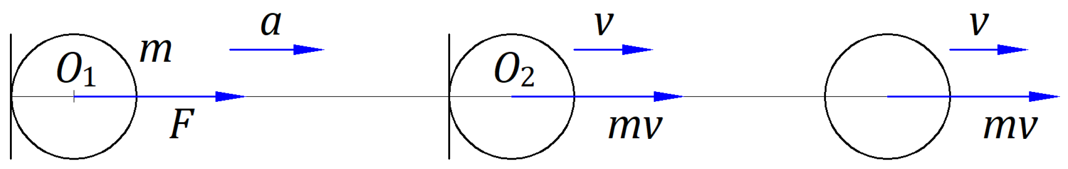
Figure 2.
Balls are emitted at a velocity V by a moving source at velocity v.
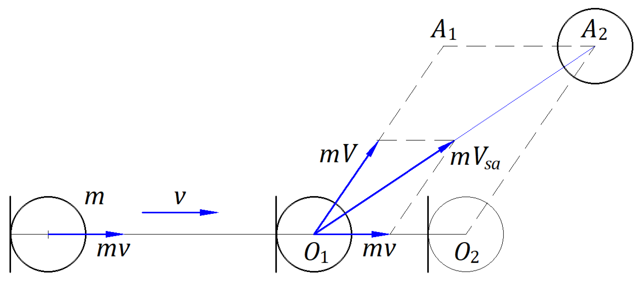
Figure 3.
The ballistic law applies to balls emitted by a source in motion.
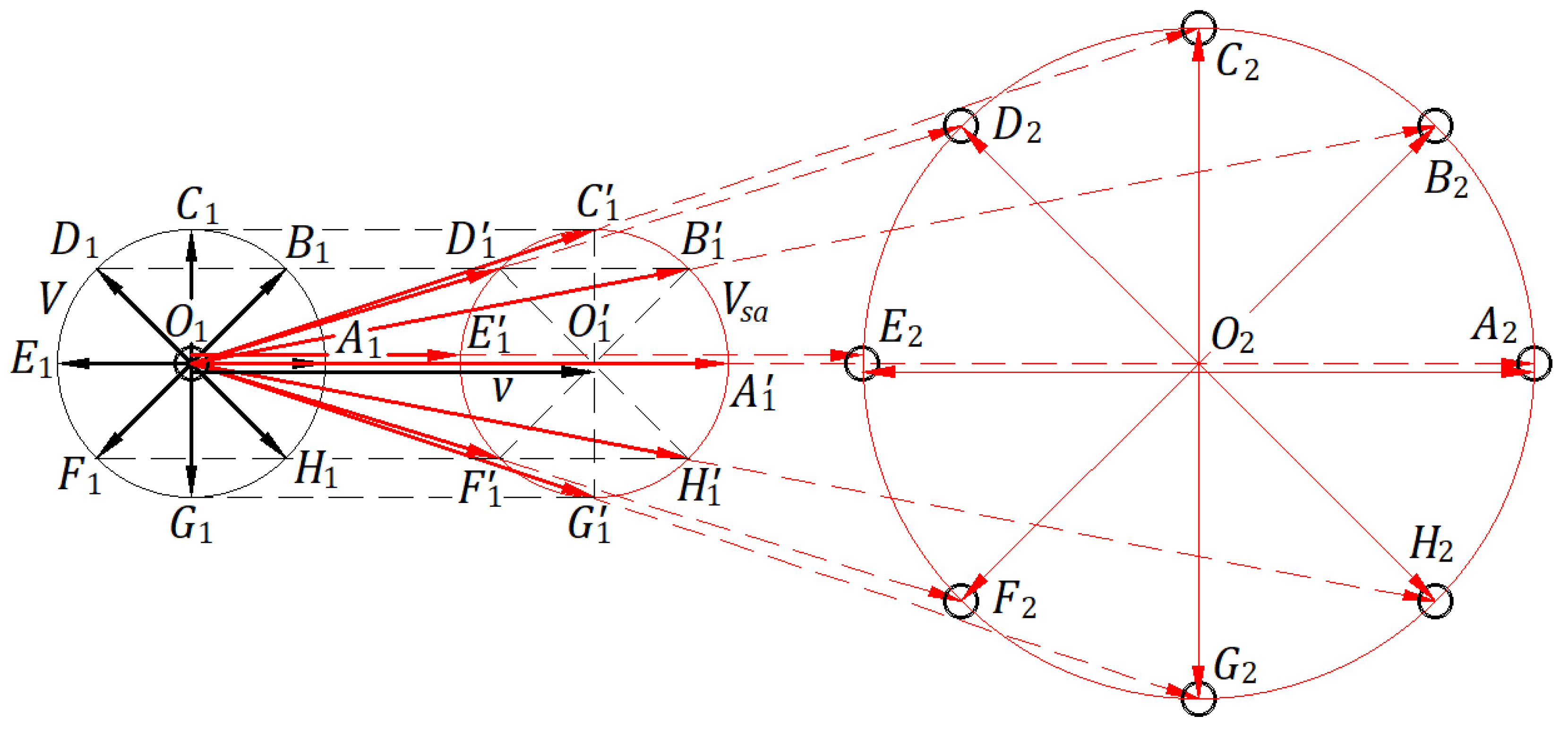
Figure 4.
Elastic collision of two balls moving in opposite directions.
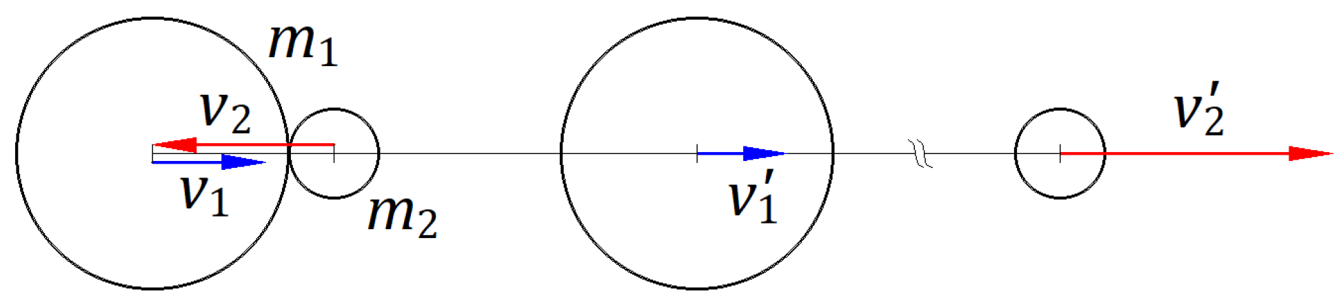
Figure 5.
Elastic collision of a wall and a ball moving in opposite directions.
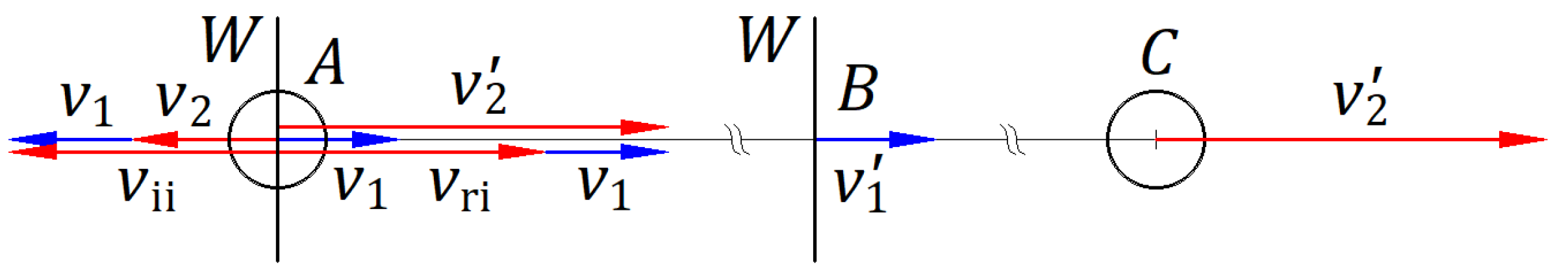
Figure 6.
Elastic reflection of a ball by a moving wall.
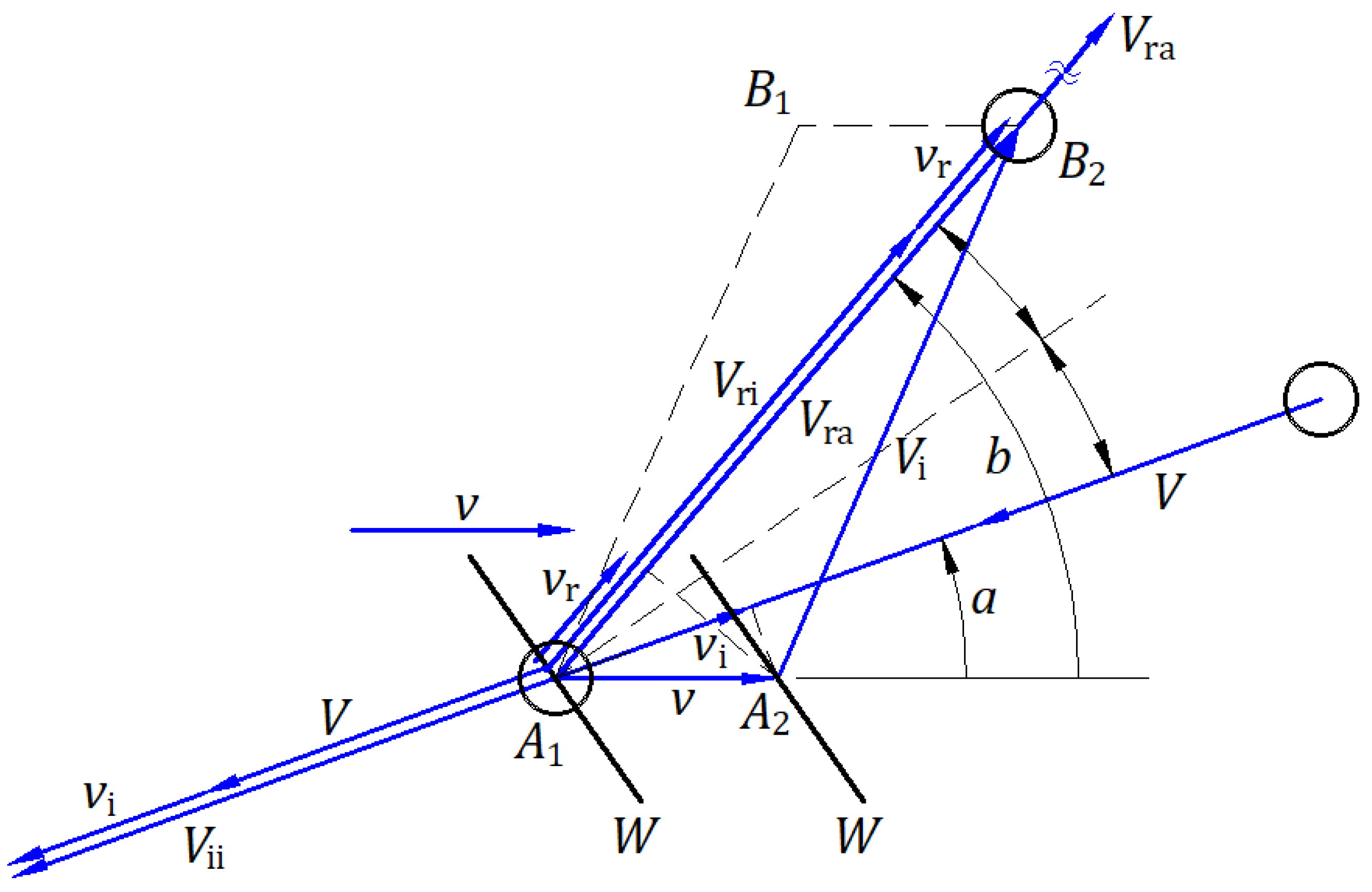
Figure 7.
Emission, propagation, and reflection of balls in the absolute frame and an inertial frame.
Figure 7.
Emission, propagation, and reflection of balls in the absolute frame and an inertial frame.
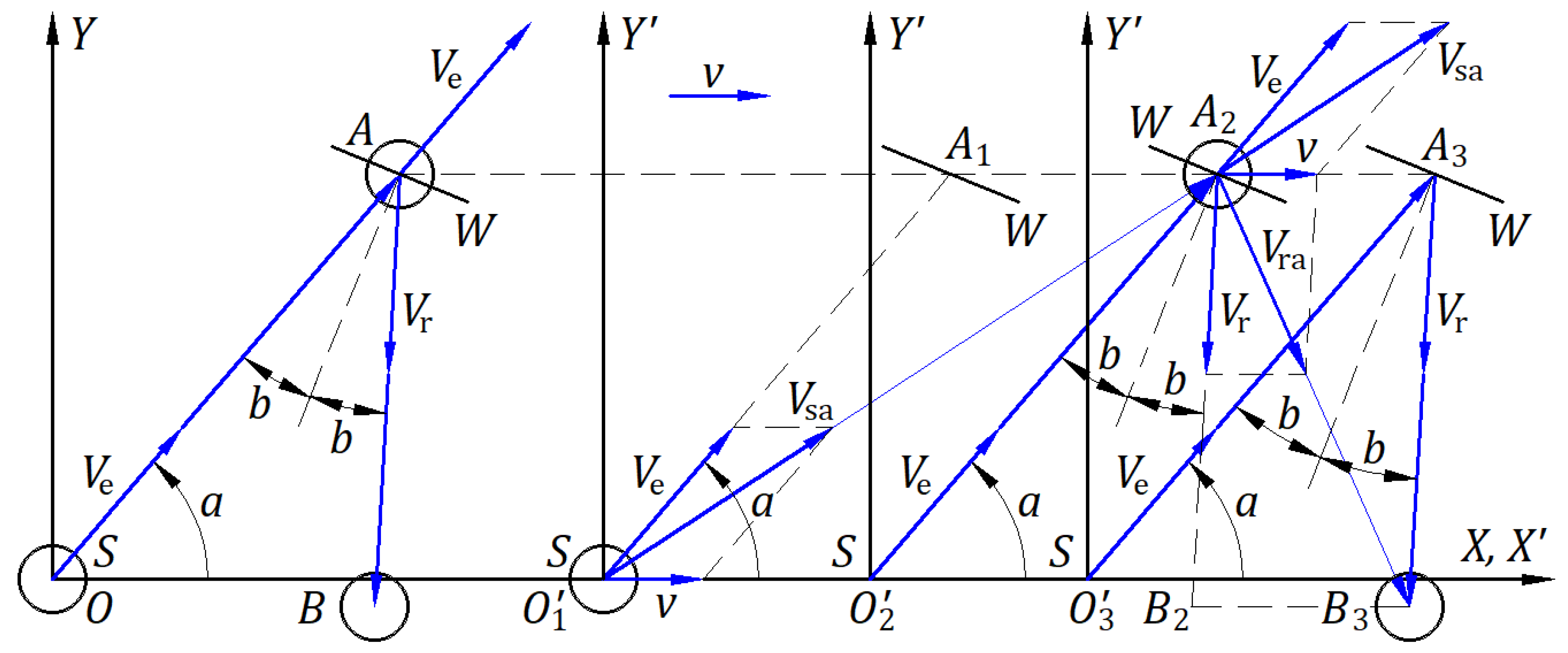
Figure 8.
The ballistic law applies to light emitted by a source in motion.
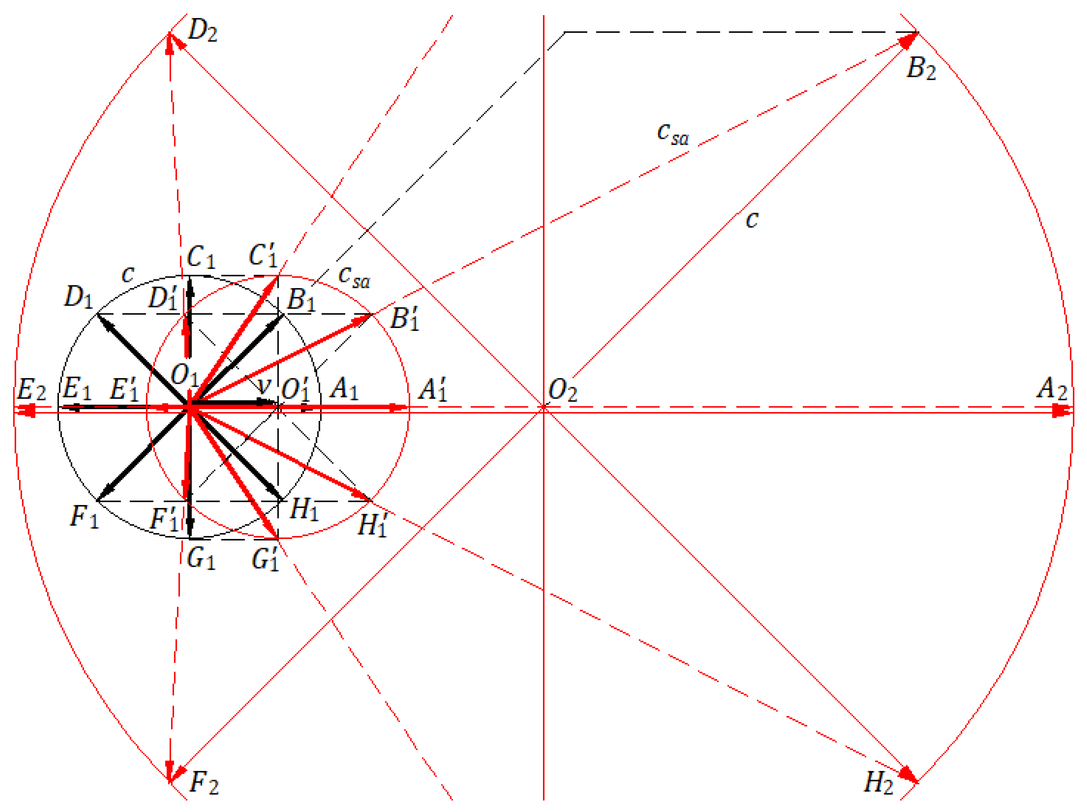
Figure 9.
Reflection of light by a moving mirror.
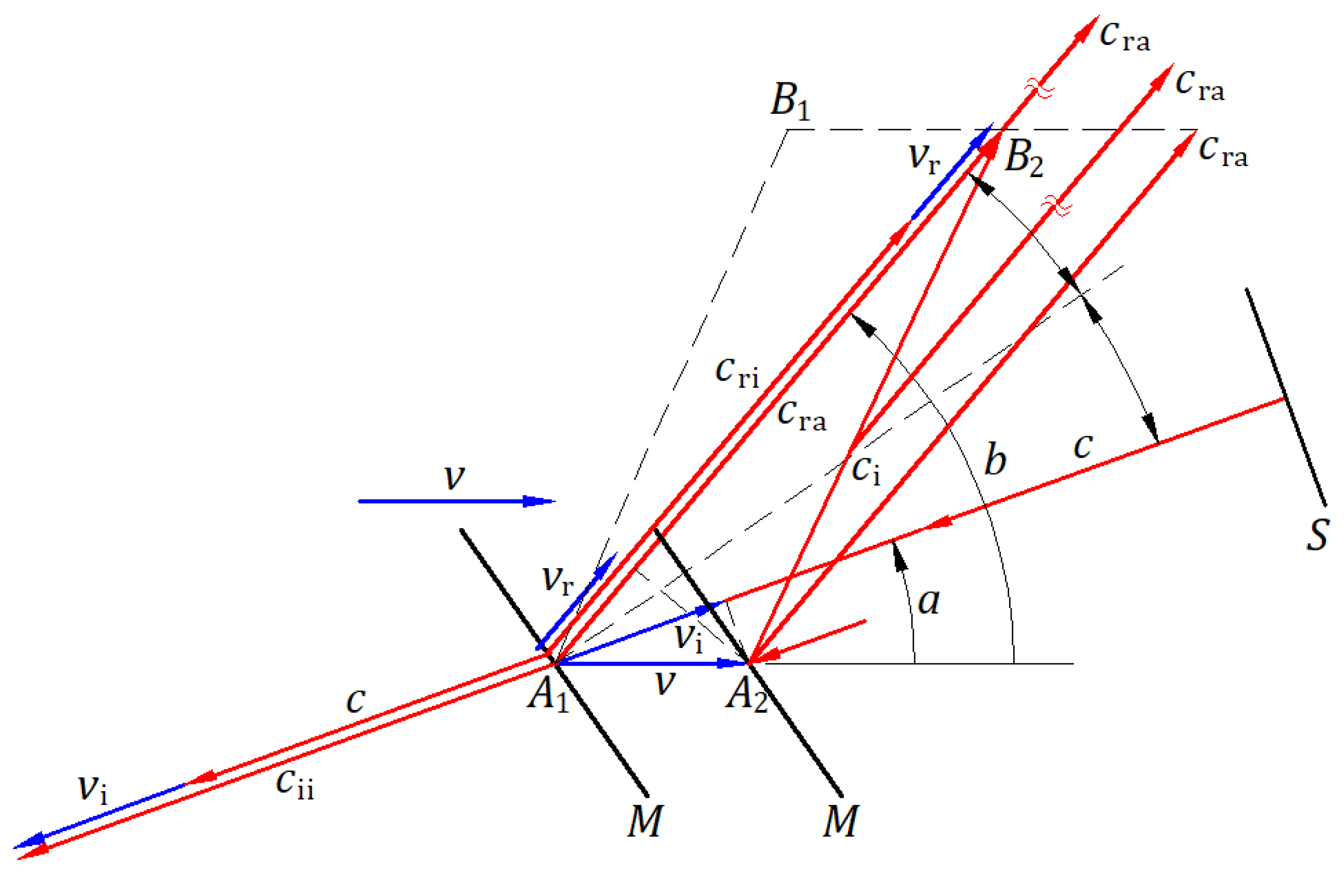
Figure 10.
Emission, propagation, and reflection of light in the absolute frame and an inertial frame.
Figure 10.
Emission, propagation, and reflection of light in the absolute frame and an inertial frame.
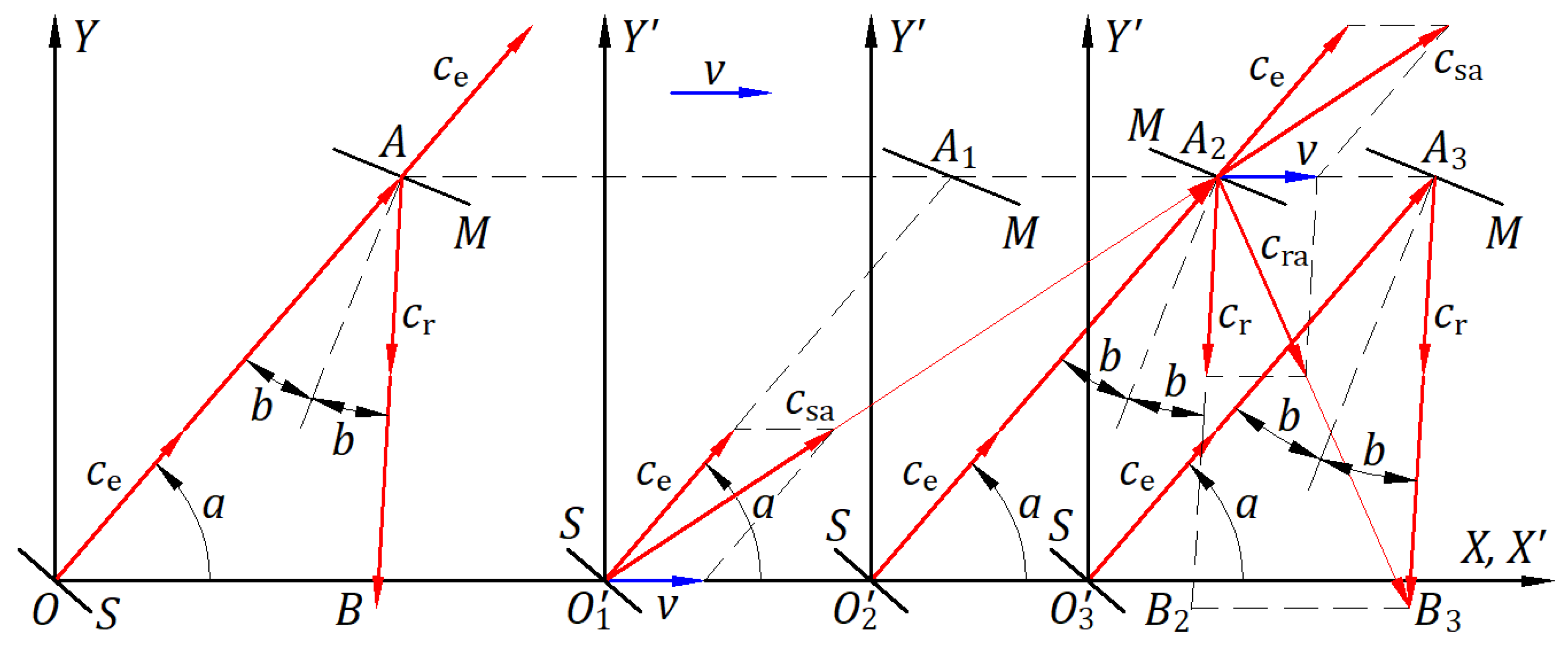
Figure 11.
A boson as a carrier decaying at a mechanical speed near the speed of light .
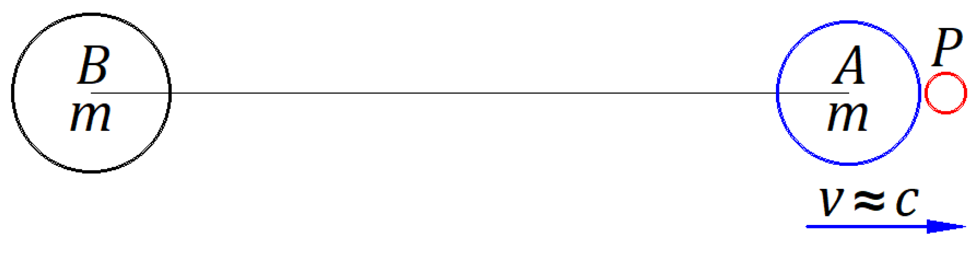
Figure 12.
Observation of a star in the universe considering (a) the ballistic law of light and (b) the constancy of light speed.
Figure 12.
Observation of a star in the universe considering (a) the ballistic law of light and (b) the constancy of light speed.
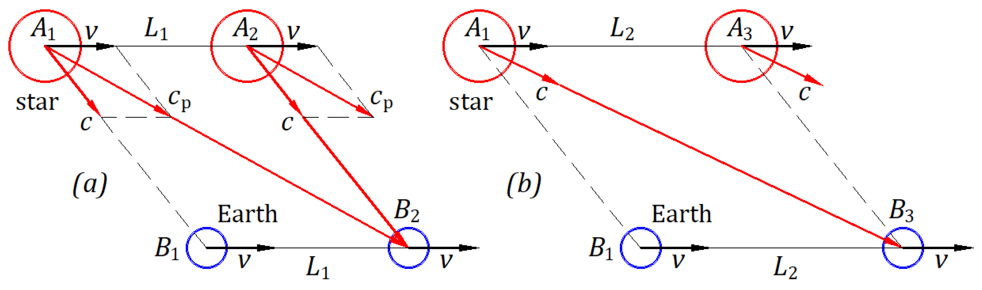
Figure 13.
Observation of a star’s orbit.
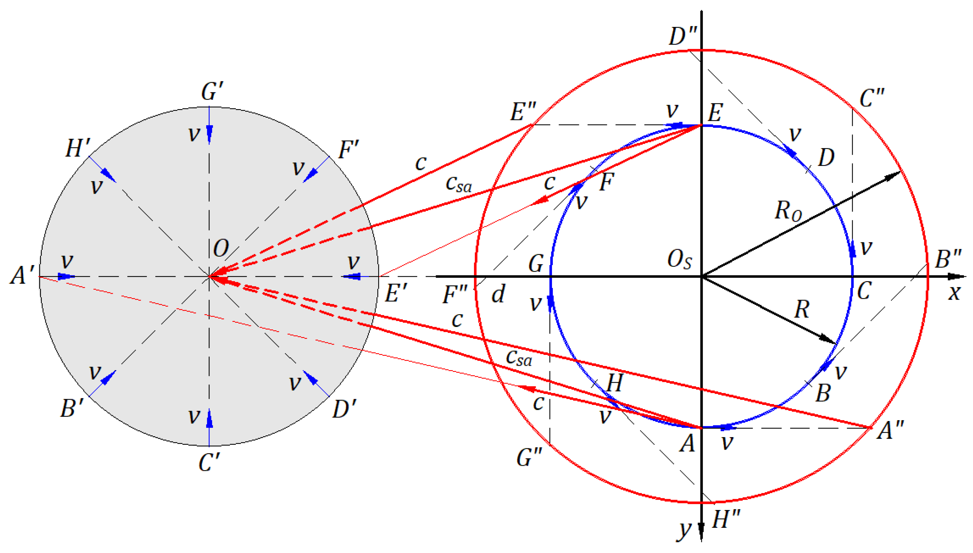
Figure 14.
Galilean coordinates of a spherical light wavefront from a stationary frame shared in an inertial frame.
Figure 14.
Galilean coordinates of a spherical light wavefront from a stationary frame shared in an inertial frame.
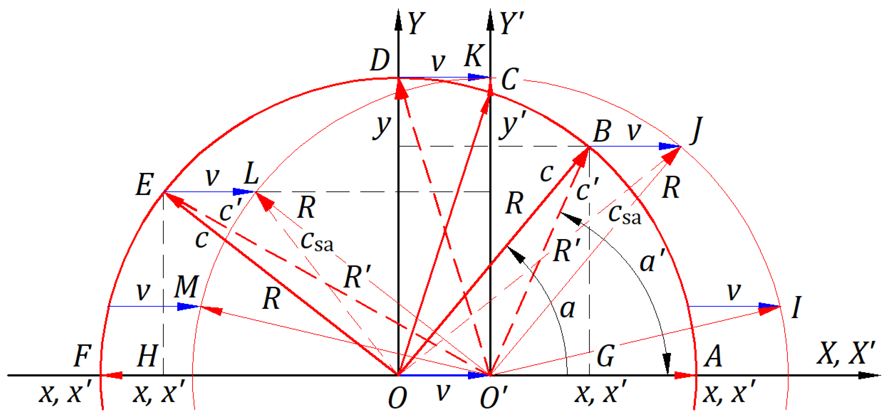
Figure 15.
Lorentz’s transformation applied to a circular wavefront of light from a stationary frame to an inertial frame.
Figure 15.
Lorentz’s transformation applied to a circular wavefront of light from a stationary frame to an inertial frame.
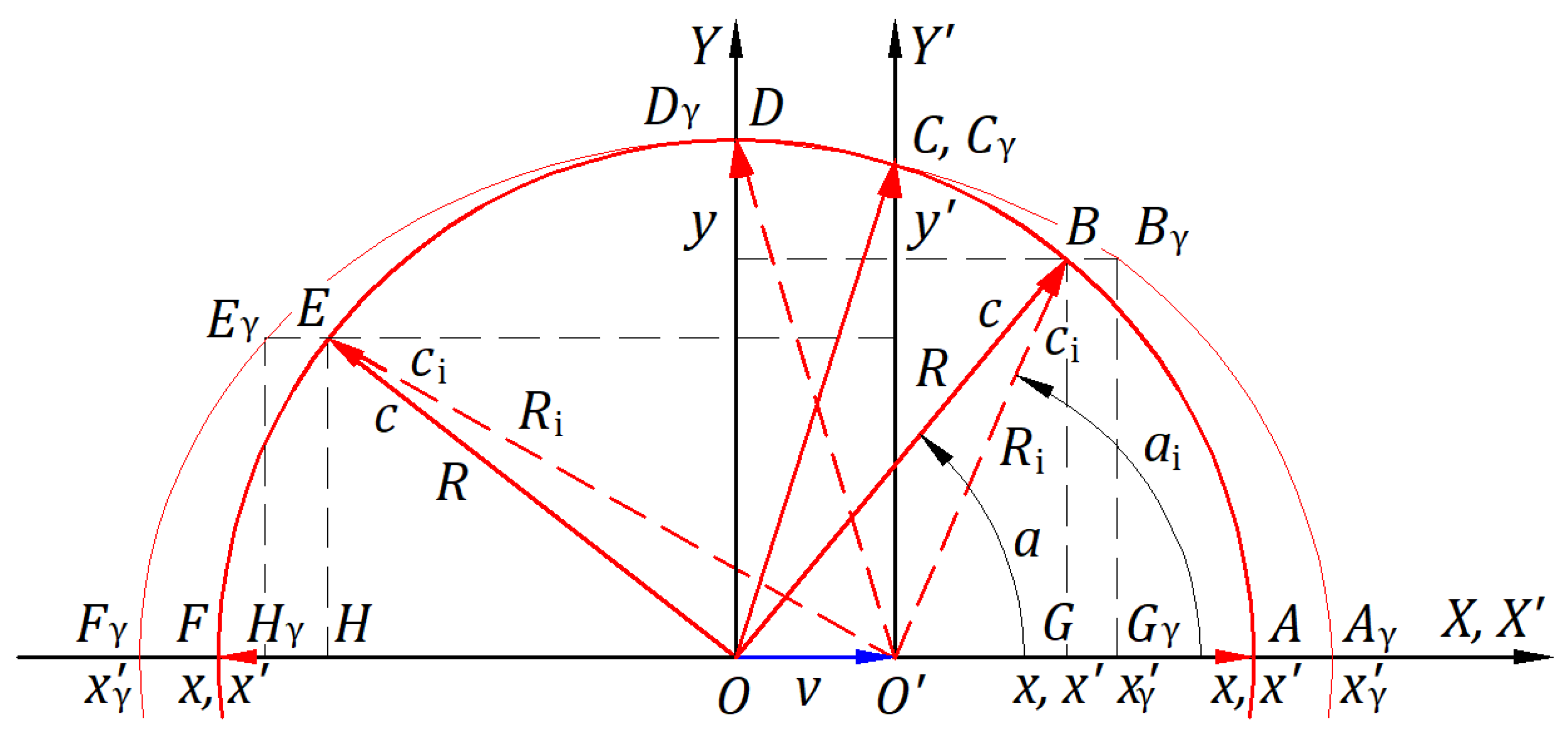
Figure 16.
Absolute light paths given in number of wavelengths: (a) For waves emitted by a source at rest. (b) For waves emitted by a moving source, disregarding the ballistic law. (c) For waves emitted by a moving source, when considering the ballistic law.
Figure 16.
Absolute light paths given in number of wavelengths: (a) For waves emitted by a source at rest. (b) For waves emitted by a moving source, disregarding the ballistic law. (c) For waves emitted by a moving source, when considering the ballistic law.
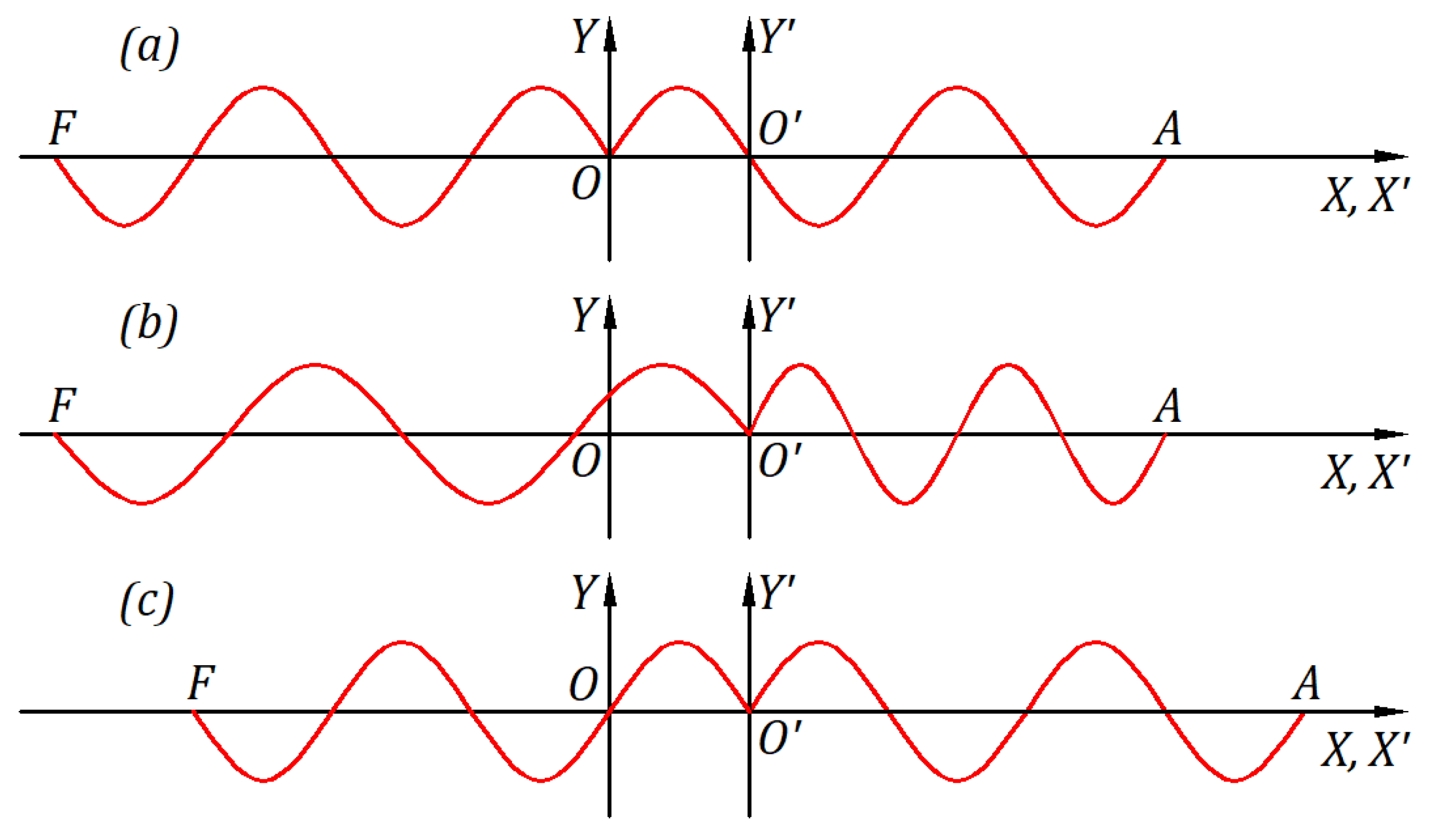
Figure 17.
Doppler Effect observation.
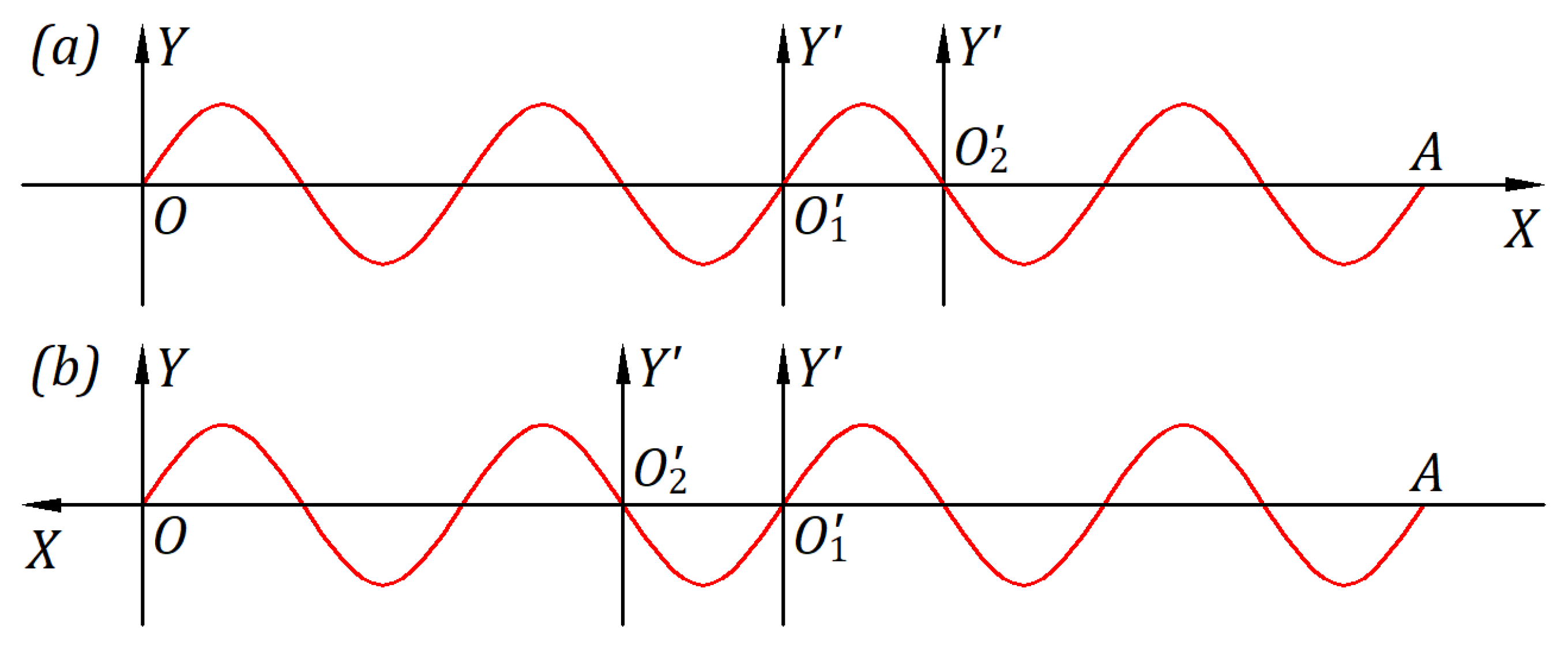

Table 1.
Numerical calculation for and at time s, function of angle .
| [°] | 0 | 88 |
| [m] | 2.99970000000000E+08 | 1.04398490107503E+07 |
| [m/s] | 3.00000000000000E+08 | 8.62078429116235E+09 |
| 89.99 | 89.9942704220391 | 89.9942704220392 |
| 2.23598772940828E+04 | 2.41565430769697E-07 | 2.24728864850476E-07 |
| 4.02506676112310E+12 | 3.72569863424722E+23 | 4.00482597595470E+23 |
| 90 | 92 | 180 |
| 2.99999999999816E+04 | 1.04998490107502E+07 | 3.00030000000000E+08 |
| 3.00000001500184E+12 | 8.57158178682134E+09 | 3.00000000000000E+08 |
Disclaimer/Publisher’s Note: The statements, opinions and data contained in all publications are solely those of the individual author(s) and contributor(s) and not of MDPI and/or the editor(s). MDPI and/or the editor(s) disclaim responsibility for any injury to people or property resulting from any ideas, methods, instructions or products referred to in the content. |
© 2025 by the authors. Licensee MDPI, Basel, Switzerland. This article is an open access article distributed under the terms and conditions of the Creative Commons Attribution (CC BY) license (http://creativecommons.org/licenses/by/4.0/).
Copyright: This open access article is published under a Creative Commons CC BY 4.0 license, which permit the free download, distribution, and reuse, provided that the author and preprint are cited in any reuse.


